EP3760339A1 - Continuous steel casting method - Google Patents
Continuous steel casting method Download PDFInfo
- Publication number
- EP3760339A1 EP3760339A1 EP19760827.6A EP19760827A EP3760339A1 EP 3760339 A1 EP3760339 A1 EP 3760339A1 EP 19760827 A EP19760827 A EP 19760827A EP 3760339 A1 EP3760339 A1 EP 3760339A1
- Authority
- EP
- European Patent Office
- Prior art keywords
- strand
- reduction
- solid phase
- range
- phase fraction
- Prior art date
- Legal status (The legal status is an assumption and is not a legal conclusion. Google has not performed a legal analysis and makes no representation as to the accuracy of the status listed.)
- Granted
Links
Images


Classifications
-
- B—PERFORMING OPERATIONS; TRANSPORTING
- B22—CASTING; POWDER METALLURGY
- B22D—CASTING OF METALS; CASTING OF OTHER SUBSTANCES BY THE SAME PROCESSES OR DEVICES
- B22D11/00—Continuous casting of metals, i.e. casting in indefinite lengths
- B22D11/16—Controlling or regulating processes or operations
- B22D11/20—Controlling or regulating processes or operations for removing cast stock
-
- B—PERFORMING OPERATIONS; TRANSPORTING
- B22—CASTING; POWDER METALLURGY
- B22D—CASTING OF METALS; CASTING OF OTHER SUBSTANCES BY THE SAME PROCESSES OR DEVICES
- B22D11/00—Continuous casting of metals, i.e. casting in indefinite lengths
- B22D11/12—Accessories for subsequent treating or working cast stock in situ
- B22D11/128—Accessories for subsequent treating or working cast stock in situ for removing
- B22D11/1287—Rolls; Lubricating, cooling or heating rolls while in use
-
- B—PERFORMING OPERATIONS; TRANSPORTING
- B22—CASTING; POWDER METALLURGY
- B22D—CASTING OF METALS; CASTING OF OTHER SUBSTANCES BY THE SAME PROCESSES OR DEVICES
- B22D11/00—Continuous casting of metals, i.e. casting in indefinite lengths
- B22D11/04—Continuous casting of metals, i.e. casting in indefinite lengths into open-ended moulds
- B22D11/041—Continuous casting of metals, i.e. casting in indefinite lengths into open-ended moulds for vertical casting
-
- B—PERFORMING OPERATIONS; TRANSPORTING
- B22—CASTING; POWDER METALLURGY
- B22D—CASTING OF METALS; CASTING OF OTHER SUBSTANCES BY THE SAME PROCESSES OR DEVICES
- B22D11/00—Continuous casting of metals, i.e. casting in indefinite lengths
- B22D11/12—Accessories for subsequent treating or working cast stock in situ
- B22D11/1206—Accessories for subsequent treating or working cast stock in situ for plastic shaping of strands
-
- B—PERFORMING OPERATIONS; TRANSPORTING
- B22—CASTING; POWDER METALLURGY
- B22D—CASTING OF METALS; CASTING OF OTHER SUBSTANCES BY THE SAME PROCESSES OR DEVICES
- B22D11/00—Continuous casting of metals, i.e. casting in indefinite lengths
- B22D11/12—Accessories for subsequent treating or working cast stock in situ
- B22D11/128—Accessories for subsequent treating or working cast stock in situ for removing
- B22D11/1282—Vertical casting and curving the cast stock to the horizontal
-
- B—PERFORMING OPERATIONS; TRANSPORTING
- B22—CASTING; POWDER METALLURGY
- B22D—CASTING OF METALS; CASTING OF OTHER SUBSTANCES BY THE SAME PROCESSES OR DEVICES
- B22D11/00—Continuous casting of metals, i.e. casting in indefinite lengths
- B22D11/16—Controlling or regulating processes or operations
-
- B—PERFORMING OPERATIONS; TRANSPORTING
- B22—CASTING; POWDER METALLURGY
- B22D—CASTING OF METALS; CASTING OF OTHER SUBSTANCES BY THE SAME PROCESSES OR DEVICES
- B22D11/00—Continuous casting of metals, i.e. casting in indefinite lengths
- B22D11/16—Controlling or regulating processes or operations
- B22D11/20—Controlling or regulating processes or operations for removing cast stock
- B22D11/207—Controlling or regulating processes or operations for removing cast stock responsive to thickness of solidified shell
Definitions
- the present invention relates to a continuous steel casting method in which the porosity formation and component segregation that occur in a central portion of a strand during continuous casting are prevented.
- solidification shrinkage occurs.
- the solidification shrinkage causes unsolidified molten steel to be drawn and flow in the withdrawal direction of the strand.
- solute elements such as C, P, Mn, and S are concentrated (the unsolidified molten steel is referred to as concentrated molten steel).
- the solute elements solidify in a central portion of the slab, causing center segregation.
- the causes of the flow of the concentrated molten steel in the final stage of solidification include, in addition to the solidification shrinkage described above, bulging of the strand between rolls due to the ferrostatic pressure of the molten steel and roll alignment mismatches between strand support rolls.
- the center segregation causes deterioration in the quality of steel products, particularly steel plates.
- sour gas causes hydrogen-induced cracking starting from the center segregation.
- the same problem occurs in marine structures, storage tanks, oil tanks, etc.
- steel materials are often required to be used in severe use environments such as lower temperature environments and more corrosive environments, and the importance of reducing the center segregation of the strand is increasing.
- one effective method is to cast a strand that is in the final stage of solidification and has an unsolidified layer while the strand is gradually rolled using a plurality of pairs of strand support rolls (this method is referred to as a "soft reduction method in the final stage of solidification”).
- a strand that is in the final stage of solidification and has an unsolidified layer is rolled by about 10 mm or more using one pair or 2 or 3 pairs of reduction rolls (this method is referred to as a "large reduction method in the final stage of solidification").
- the soft reduction method in the final stage of solidification is the following technique.
- Reduction rolls are disposed in the casting direction in a zone close to a solidification completion position of the strand (this zone is referred to as a "soft reduction zone"), and a strand is gradually rolled during continuous casting using the reduction rolls at a rolling reduction rate (0.3 to 1.5 mm/min) approximately corresponding to the amount of solidification shrinkage.
- a rolling reduction rate 0.3 to 1.5 mm/min
- the large reduction method in the final stage of solidification is a technique in which a strand is rolled using one pair or 2 or 3 pairs of reduction rolls disposed in a zone close to a solidification completion position of the strand to push out the concentrated molten steel present between dendrite arms toward the upstream side in the casting direction to thereby reduce the center segregation of the strand.
- Patent Literature 1 discloses a large reduction method in the final stage of solidification.
- a strand is intentionally bulged by 3% or more and 25% or less of the thickness of the strand at the start of bulging. Then a portion of the strand in which the solid phase fraction in its central portion is from 0.2 to 0.7 is rolled by a thickness reduction corresponding to from 30% to 70% of the amount of bulging using a pair of reduction rolls.
- Patent Literature 2 discloses a large reduction method in the final stage of solidification.
- guide rolls disposed in a prescribed region between a position corresponding to a liquidus crater end of a strand and a position corresponding to its solidus crater end are such that the gap between the guide rolls in the thickness direction of the strand (its short side direction) is increased.
- the strand is intentionally bulged by a total of 5 mm to less than 20 mm.
- a portion of the strand in which the solid phase fraction in the central portion of the strand is 0.1 to 0.8 is rolled at a reduction of 0.5 to 1.0 times the amount of bulging using at least one pair of reduction rolls to thereby reduce center segregation.
- Patent Literature 1 and Patent Literature 2 the amount of intentional bulging is large, and it is therefore feared that cracking may occur in the strand when the strand is intentionally bulged. Moreover, since the reduction per reduction roll is large, a robust rolling facility that can withstand a high load is necessary. Therefore, the cost of the facility is high, and it is feared that internal cracking may occur in the strand during rolling. Moreover, when the rolling reduction relative to the increase in the gap between the rolls is insufficient, porosity may remain present in the central portion of the strand.
- Patent Literature 3 discloses a rolling method in which bulging and convex rolls are utilized.
- the amount of bulging is large, and there is a possibility that internal cracking may occur.
- Patent Literature 4 discloses a method for reducing the porosity by rolling a widthwise central portion of a strand including an unsolidified portion in a region in which the solid phase fraction in a thicknesswise central portion of the strand is 0.8 or more and less than 1.0.
- Patent Literature 4 as in Patent Literature 1, the rolling reduction per reduction roll is large, and a robust rolling facility that can withstand a high load is necessary. Therefore, the cost of the facility is high, and it is feared that internal cracking may occur in the strand during rolling.
- NPL 1 OHNAKA Itsuo, "Introduction to Heat Transfer and Solidification Analysis by Computers, Applications to Casting Processes," MARUZEN Co., Ltd. (Tokyo), 1985, p. 201-202
- the present invention has been made in view of the foregoing problems, and it is an object to provide a continuous steel casting method in which the amount D 0 of intentional bulging of the strand (the increase in the thickness of the strand) formed using guide rolls is adjusted to 10% or less of the thickness of the strand at the outlet of a mold to prevent the occurrence of internal cracking and the porosity formation, in which, while the total rolling reduction is prescribed, soft reduction is applied, so that center segregation can be effectively reduced using a relatively small rolling load without using a facility with high rolling ability, and in which remaining porosity is eliminated by stepwise rolling after solidification.
- the strand can be subjected to soft reduction while the total rolling reduction is prescribed without the occurrence of cracking and the porosity formation inside the strand, so that center segregation can be effectively reduced using a relatively small rolling load without using a facility with high rolling ability.
- the solidified strand is then continuously rolled stepwise before the temperature of the central portion of the strand is reduced largely. Therefore, remaining porosity can be compression-bonded using a smaller rolling load, so that the occurrence of internal cracking can be prevented.
- a gap between strand support rolls facing each other with a strand in a rectangular shape interposed therebetween is increased toward a downstream side in a casting direction to thereby bulge the strand having an unsolidified layer thereinside such that a thickness between long-side surfaces of the strand increases within the range of 0.1% or more and 10% or less of the thickness of the strand inside a mold.
- a total rolling reduction and a reduction gradient satisfy formulas (1) and (2) below when a solid phase fraction in a central portion of the strand is within the range of 0.2 or more and less than 0.9, and the total rolling reduction and the reduction gradient satisfy formulas (3) and (4) below when the solid phase fraction in the central portion of the strand is within the range of 0.9 or more: 0.5 ⁇ R t 1 / D 0 ⁇ 1.0 , 0.5 ⁇ R g 1 ⁇ 3.0 , 0.2 ⁇ R t 2 / D 0 ⁇ 1.0 , 0.1 ⁇ R g 2 ⁇ 1.5
- R t1 the total rolling reduction (mm) of the strand when the solid phase fraction is within the range of 0.2 or more and less than 0.9
- D 0 the amount of bulging (mm) of the strand
- R g1 the reduction gradient (mm/m) of the strand when the solid phase fraction is
- Fig. 1 is a schematic illustration showing a continuous casting machine 1 to which the continuous steel casting method according to the embodiment of the present invention is applied.
- the continuous casting machine 1 includes a tundish 3 into which molten steel 2 is poured from a molten steel ladle, a copper-made mold 5 that cools the molten steel 2 poured from the tundish 3 through a submerged nozzle 4, and a plurality of segments 7 that convey a semi-solidified strand 6 withdrawn from the mold 5.
- the semi-solidified strand 6 includes thereinside an unsolidified layer 6a.
- Fig. 2 is an enlarged schematic illustration of a segment 7 in the continuous casting machine 1
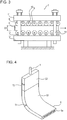
- Fig. 3 is a side view of the segments 7 in a plane perpendicular to the conveying direction of the strand 6.
- the segments 7 include driving rolls 8 that apply a pressing force to the strand 6 and guide rolls 9.
- Each of the guide rolls is fixed to an upper frame 11 or a lower frame 12 through a bearing 10.
- the upper frame 11 and the lower frame 12 are supported by an upstream strut 13 and a downstream strut 14.
- the driving rolls and the guide rolls are collectively referred to as strand support rolls.
- the strand support rolls are disposed at positions facing each other with the strand 6 interposed therebetween.
- the upstream strut 13 and the downstream strut 14 determine the amount of soft reduction applied to the strand 6 by the segments 7 as a whole. Since each of the plurality of guide rolls 9 is fixed to the upper frame 11 or the lower frame 12 through a corresponding bearing as described above, the gap between the upper guide rolls and the lower guide rolls can be adjusted by extending or contracting the length of the struts using, for example, a worm jack. By setting the roll gap of a segment to be larger than the roll gap of a segment immediately upstream thereof, the amount of bulging can be set. By setting the gap between guide rolls in the upstream side to be larger than the gap between guide rolls in the downstream side, a soft reduction gradient can be set.
- the gap D1 between the strand support rolls facing each other with the strand 6 interposed therebetween is increased toward the downstream side in the casting direction. Therefore, the strand 6 in a rectangular shape having the unsolidified layer 6a thereinside is bulged such that the thickness T1 between the long-side surfaces of the strand 6 increases within the range of from 0.1% to 10% of the thickness T2 of the strand in the mold 5. Fig.
- the bulging in the present invention is intentional building and is hereinafter referred to simply as "bulging.”
- the reason that the amount of bulging is set to 0.1% or more is that 0.1% is an estimate of the minimum necessary amount of bulging necessary to prevent an excessively large load from being applied to the strand, and the reason that the amount of bulging is set to 10% or less is to prevent excessive internal strain caused by the intentional bulging to thereby prevent internal cracking.
- the intentional bulging is started at a point where the solid phase fraction in the central portion is 0 and is stopped when the amount of bulging reaches a prescribed amount that is within the range of from 0.1% to 10% (preferably from 1% to 5%) of the thickness of the strand in the mold.
- the bulging is stopped in a region in which the solid phase fraction in the central portion is less than 0.1.
- the long-side surfaces of the strand are rolled using a plurality of guide rolls.
- a portion of the strand in which the solid phase fraction in the thicknesswise central portion of the strand is 0.2 or more and less than 0.9 is rolled using guide rolls by an amount of 50% or more and 100% or less of the amount of bulging.
- the solid phase fraction in the thicknesswise central portion of the strand (hereinafter referred to simply as the "solid phase fraction in the central portion" or the "solid phase fraction”) is the solid phase fraction on a center line in the thickness direction in the strand excluding widthwise edges and may be typified by the solid phase fraction in a portion at the widthwise center (and the thicknesswise center) of the strand.
- the center segregation in the strand due to the flow of the molten steel in the final stage of solidification can be reduced.
- the rolling reduction By setting the rolling reduction to 100% or less of the amount of bulging, a solidifying shell in fully solidified short-side portions is not rolled, and a rolling load when a portion in which the solid phase fraction is within the range of 0.9 or more is rolled can be reduced.
- the reduction gradient within the range of 0.5 to 3.0 mm/m, the strand can be rolled at an appropriate rolling rate, and the center segregation can be effectively reduced.
- the operation is performed such that formulas (1) and (2) are satisfied.
- R t1 the total rolling reduction (mm) of the strand when the solid phase fraction is within the range of 0.2 or more and less than 0.9
- D 0 the amount of bulging (mm) of the strand
- R g1 the reduction gradient (mm/m) of the strand when the solid phase fraction is within the range of 0.2 or more and less than 0.9.
- the strand is rolled using guide rolls by an amount of 20% or more and 100% or less of the amount of bulging.
- the reduction gradient within the range of 0.1 to 1.5 mm/m, the porosity can be effectively reduced while an excessive load is not applied to the segments.
- the operation is performed such that formulas (3) and (4) are satisfied.
- the rolling may be continued after the solid phase fraction in the central portion has reached 1.0. However, the rolling is finished such that the total rolling reduction is within the range defined by formula (3).
- R t2 the total rolling reduction (mm) of the strand when the solid phase fraction is within the range of 0.9 or more
- D 0 the amount of bulging (mm) of the strand
- R g2 the reduction gradient (mm/m) of the strand when the solid phase fraction is within the range of 0.9 or more.
- the effects of the present invention can be obtained so long as the operation is performed while the above operating conditions are satisfied. It is more preferable that the operating conditions are controlled such that they fall within the above ranges.
- the solid phase fraction in the central portion can be determined in advance by heat transfer-solidification analysis.
- numerical computations may be performed using, for example, an "enthalpy method" described in Non Patent Literature 1.
- the accuracy of the heat transfer-solidification analysis was checked in advance by a method such as a rivet pin shooting test, the measurement of surface temperature, or the measurement of the solid phase fraction using ultrasonic waves and was found to be sufficient for embodying the present invention.
- the solidification completion point can vary during casting. However, by setting the range of the soft reduction by the guide rolls to be wide, the portion in which the solid phase fraction is 0.9 or less can be prevented from being located outside the rolling reduction range.
- a slab continuous casting machine of the same type as the slab continuous casting machine in Fig. 1 was used to perform a test in which low-carbon aluminum-killed steel was subjected to continuous casting.
- Main components of the steel are C: 0.03 to 0.2% by mass, Si: 0.05 to 0.5% by mass, Mn: 0.8 to 1.8% by mass, P: less than 0.02% by mass, and S: less than 0.005% by mass.
- the size of the strand the thickness is 250 mm to 300 mm, and the width is 1900 to 2100 mm.
- the withdrawal speed of the strand is 0.9 to 1.4 m/min.
- the rolling segments include a pair of driving rolls and guide rolls, and the length of one segment is 2 m.
- Fig. 5 shows an example of the roll gap in the Examples.
- Tables 1 and 2 show casting conditions 1 to 11 in the continuous steel casting method according to the embodiment of the present invention and data on the measurement of the degree of center segregation, porosity, internal cracking, and surface flaws in cast slabs. For comparison, the casting test was conducted under conditions 12 to 20 outside the ranges of the present invention.
- the concentration of carbon (% by mass) in a central portion of a cross section of a slab was analyzed in the thickness direction.
- the maximum value of the carbon concentration was denoted as Cmax
- the average carbon concentration i.e., the carbon concentration in molten steel
- C 0 the average carbon concentration
- Cmax/C 0 was defined as the degree of center segregation. Specifically, in this definition, the closer the degree of center segregation is to 1, the lower the center segregation.
- the degree of center segregation was 1.10 or more, the center segregation was judged to be poor, and a poor rating was given.
- Porosity in the strand were judged as follows. A thicknesswise central portion of the slab before rolling was subjected to ultrasonic flaw detection. When porosity with a pore diameter of 2 mm or more was found, the slab was judged to have porosity, and a poor rating was given.
- conditions 12 performed as comparative conditions, the casting was performed under the conditions in which rolling was not performed when the solid phase fraction was within the range of 0.9 or more. Since all the total rolling reduction and the reduction gradient of the strand when the solid phase fraction was within the range of 0.2 or more and less than 0.9 were within the ranges of the present invention, the degree of center segregation was low, but porosity was formed.
- rolling was performed when the solid phase fraction was within the range of 0.9 or more. The total rolling reduction when the solid phase fraction was within the range of 0.2 or more and less than 0.9 and also the total rolling reduction when the solid phase fraction was within the range of 0.9 or more were larger than the ranges of the present invention.
Landscapes
- Engineering & Computer Science (AREA)
- Mechanical Engineering (AREA)
- Continuous Casting (AREA)
Abstract
Description
- The present invention relates to a continuous steel casting method in which the porosity formation and component segregation that occur in a central portion of a strand during continuous casting are prevented.
- In the process of solidification during continuous casting, solidification shrinkage occurs. The solidification shrinkage causes unsolidified molten steel to be drawn and flow in the withdrawal direction of the strand. In the unsolidified molten steel, solute elements such as C, P, Mn, and S are concentrated (the unsolidified molten steel is referred to as concentrated molten steel). When the flow of the concentrated molten steel occurs, the solute elements solidify in a central portion of the slab, causing center segregation. The causes of the flow of the concentrated molten steel in the final stage of solidification include, in addition to the solidification shrinkage described above, bulging of the strand between rolls due to the ferrostatic pressure of the molten steel and roll alignment mismatches between strand support rolls.
- The center segregation causes deterioration in the quality of steel products, particularly steel plates. For example, in line pipe materials for oil transportation and natural gas transportation, sour gas causes hydrogen-induced cracking starting from the center segregation. The same problem occurs in marine structures, storage tanks, oil tanks, etc. In recent years, steel materials are often required to be used in severe use environments such as lower temperature environments and more corrosive environments, and the importance of reducing the center segregation of the strand is increasing.
- Therefore, many measures directed toward reducing the center segregation or the porosity in a strand have been proposed over process steps from the continuous casting step to the rolling step. Among them, one effective method is to cast a strand that is in the final stage of solidification and has an unsolidified layer while the strand is gradually rolled using a plurality of pairs of strand support rolls (this method is referred to as a "soft reduction method in the final stage of solidification"). In another effective method, a strand that is in the final stage of solidification and has an unsolidified layer is rolled by about 10 mm or more using one pair or 2 or 3 pairs of reduction rolls (this method is referred to as a "large reduction method in the final stage of solidification").
- The soft reduction method in the final stage of solidification is the following technique. Reduction rolls are disposed in the casting direction in a zone close to a solidification completion position of the strand (this zone is referred to as a "soft reduction zone"), and a strand is gradually rolled during continuous casting using the reduction rolls at a rolling reduction rate (0.3 to 1.5 mm/min) approximately corresponding to the amount of solidification shrinkage. In this manner, the formation of voids in a central portion of the strand and the flow of the concentrated molten steel are prevented, and the center segregation of the strand is thereby reduced. The large reduction method in the final stage of solidification is a technique in which a strand is rolled using one pair or 2 or 3 pairs of reduction rolls disposed in a zone close to a solidification completion position of the strand to push out the concentrated molten steel present between dendrite arms toward the upstream side in the casting direction to thereby reduce the center segregation of the strand.
- In the soft reduction in the final stage of solidification, if the amount of rolling reduction is insufficient, center segregation and the formation of internal defects are not prevented sufficiently. If the amount of rolling reduction is excessively large, internal cracking occurs, and the internal quality of the strand deteriorates. Therefore, in the soft reduction in the final stage of solidification, it is important to control the amount of rolling reduction within an appropriate range. However, when the strand is actually subjected to soft reduction, a large load is applied to soft reduction segments and may cause the segments to deform, so that an appropriate rolling reduction may not be obtained. If the rolling reduction is insufficient, porosity remain present, and it is feared that UT defects may occur.
-
Patent Literature 1 discloses a large reduction method in the final stage of solidification. In this method, a strand is intentionally bulged by 3% or more and 25% or less of the thickness of the strand at the start of bulging. Then a portion of the strand in which the solid phase fraction in its central portion is from 0.2 to 0.7 is rolled by a thickness reduction corresponding to from 30% to 70% of the amount of bulging using a pair of reduction rolls.Patent Literature 2 discloses a large reduction method in the final stage of solidification. In this method, guide rolls disposed in a prescribed region between a position corresponding to a liquidus crater end of a strand and a position corresponding to its solidus crater end are such that the gap between the guide rolls in the thickness direction of the strand (its short side direction) is increased. In this case, the strand is intentionally bulged by a total of 5 mm to less than 20 mm. Then, a portion of the strand in which the solid phase fraction in the central portion of the strand is 0.1 to 0.8 is rolled at a reduction of 0.5 to 1.0 times the amount of bulging using at least one pair of reduction rolls to thereby reduce center segregation. InPatent Literature 1 andPatent Literature 2, the amount of intentional bulging is large, and it is therefore feared that cracking may occur in the strand when the strand is intentionally bulged. Moreover, since the reduction per reduction roll is large, a robust rolling facility that can withstand a high load is necessary. Therefore, the cost of the facility is high, and it is feared that internal cracking may occur in the strand during rolling. Moreover, when the rolling reduction relative to the increase in the gap between the rolls is insufficient, porosity may remain present in the central portion of the strand. -
Patent Literature 3 discloses a rolling method in which bulging and convex rolls are utilized. InPatent Literature 3, as inPatent Literature 1 andPatent Literature 2, the amount of bulging is large, and there is a possibility that internal cracking may occur. Moreover, there is a risk of internal cracking when solidification interfaces are compression-bonded by second rolling. -
Patent Literature 4 discloses a method for reducing the porosity by rolling a widthwise central portion of a strand including an unsolidified portion in a region in which the solid phase fraction in a thicknesswise central portion of the strand is 0.8 or more and less than 1.0. However, inPatent Literature 4, as inPatent Literature 1, the rolling reduction per reduction roll is large, and a robust rolling facility that can withstand a high load is necessary. Therefore, the cost of the facility is high, and it is feared that internal cracking may occur in the strand during rolling. -
- PTL 1: Japanese Unexamined Patent Application Publication No.
2000-288705 - PTL 2: Japanese Unexamined Patent Application Publication No.
11-156511 - PTL 3: Japanese Unexamined Patent Application Publication No.
2001-334353 - PTL 4: Japanese Unexamined Patent Application Publication No.
2007-296542 - NPL 1: OHNAKA Itsuo, "Introduction to Heat Transfer and Solidification Analysis by Computers, Applications to Casting Processes," MARUZEN Co., Ltd. (Tokyo), 1985, p. 201-202
- The present invention has been made in view of the foregoing problems, and it is an object to provide a continuous steel casting method in which the amount D0 of intentional bulging of the strand (the increase in the thickness of the strand) formed using guide rolls is adjusted to 10% or less of the thickness of the strand at the outlet of a mold to prevent the occurrence of internal cracking and the porosity formation, in which, while the total rolling reduction is prescribed, soft reduction is applied, so that center segregation can be effectively reduced using a relatively small rolling load without using a facility with high rolling ability, and in which remaining porosity is eliminated by stepwise rolling after solidification.
- The features of the present invention that solve the foregoing problems are as follows.
- [1] A continuous steel casting method, wherein, during continuous casting of steel, a gap between strand support rolls facing each other with a strand in a rectangular shape interposed therebetween is increased toward a downstream side in a casting direction to thereby bulge the strand having an unsolidified layer thereinside such that a thickness between long-side surfaces of the strand increases within the range of 0.1% or more and 10% or less of the thickness of the strand inside a mold, and wherein, when the long-side surfaces of the bulged strand are rolled by a plurality of guide rolls,
a total rolling reduction and a reduction gradient satisfy formulas (1) and (2) below when a solid phase fraction in a central portion of the strand is within the range of 0.2 or more and less than 0.9, and the total rolling reduction and the reduction gradient satisfy formulas (3) and (4) below when the solid phase fraction in the central portion of the strand is within the range of 0.9 or more:



- By applying the continuous steel casting method of the present invention, the strand can be subjected to soft reduction while the total rolling reduction is prescribed without the occurrence of cracking and the porosity formation inside the strand, so that center segregation can be effectively reduced using a relatively small rolling load without using a facility with high rolling ability. The solidified strand is then continuously rolled stepwise before the temperature of the central portion of the strand is reduced largely. Therefore, remaining porosity can be compression-bonded using a smaller rolling load, so that the occurrence of internal cracking can be prevented.
-
- [
Fig. 1] Fig. 1 is a schematic illustration showing a continuous casting machine to which a continuous steel casting method according to an embodiment of the present invention is applied. - [
Fig. 2] Fig. 2 is an enlarged schematic illustration showing a soft reduction segment in the continuous casting machine. - [
Fig. 3] Fig. 3 is a side view of soft reduction segments in a plane perpendicular to a conveying direction. - [
Fig. 4] Fig. 4 is a schematic illustration showing a strand. - [
Fig. 5] Fig. 5 shows an example of a roll gap in the present invention. - In the continuous steel casting method of the present invention, a gap between strand support rolls facing each other with a strand in a rectangular shape interposed therebetween is increased toward a downstream side in a casting direction to thereby bulge the strand having an unsolidified layer thereinside such that a thickness between long-side surfaces of the strand increases within the range of 0.1% or more and 10% or less of the thickness of the strand inside a mold. When the long-side surfaces of the bulged strand are rolled by a plurality of guide rolls, a total rolling reduction and a reduction gradient satisfy formulas (1) and (2) below when a solid phase fraction in a central portion of the strand is within the range of 0.2 or more and less than 0.9, and the total rolling reduction and the reduction gradient satisfy formulas (3) and (4) below when the solid phase fraction in the central portion of the strand is within the range of 0.9 or more:


- An example of a continuous steel casting method according to an embodiment of the present invention will be described with reference to the drawings. In
Fig. 3 , the casting direction is indicated by an arrow. -
Fig. 1 is a schematic illustration showing acontinuous casting machine 1 to which the continuous steel casting method according to the embodiment of the present invention is applied. As shown inFig. 1 , thecontinuous casting machine 1 includes atundish 3 into whichmolten steel 2 is poured from a molten steel ladle, a copper-mademold 5 that cools themolten steel 2 poured from thetundish 3 through a submergednozzle 4, and a plurality ofsegments 7 that convey asemi-solidified strand 6 withdrawn from themold 5. Thesemi-solidified strand 6 includes thereinside anunsolidified layer 6a. -
Fig. 2 is an enlarged schematic illustration of asegment 7 in thecontinuous casting machine 1, andFig. 3 is a side view of thesegments 7 in a plane perpendicular to the conveying direction of thestrand 6. As shown inFigs. 2 and3 , thesegments 7 include drivingrolls 8 that apply a pressing force to thestrand 6 and guide rolls 9. Each of the guide rolls is fixed to anupper frame 11 or alower frame 12 through abearing 10. Theupper frame 11 and thelower frame 12 are supported by anupstream strut 13 and adownstream strut 14. The driving rolls and the guide rolls are collectively referred to as strand support rolls. The strand support rolls are disposed at positions facing each other with thestrand 6 interposed therebetween. - Since the
upper frame 11 and thelower frame 12 are supported by theupstream strut 13 and thedownstream strut 14, theupstream strut 13 and thedownstream strut 14 determine the amount of soft reduction applied to thestrand 6 by thesegments 7 as a whole. Since each of the plurality of guide rolls 9 is fixed to theupper frame 11 or thelower frame 12 through a corresponding bearing as described above, the gap between the upper guide rolls and the lower guide rolls can be adjusted by extending or contracting the length of the struts using, for example, a worm jack. By setting the roll gap of a segment to be larger than the roll gap of a segment immediately upstream thereof, the amount of bulging can be set. By setting the gap between guide rolls in the upstream side to be larger than the gap between guide rolls in the downstream side, a soft reduction gradient can be set. - In the method of the present invention, to prevent internal cracking and the porosity formation in the strand, the gap D1 between the strand support rolls facing each other with the
strand 6 interposed therebetween is increased toward the downstream side in the casting direction. Therefore, thestrand 6 in a rectangular shape having theunsolidified layer 6a thereinside is bulged such that the thickness T1 between the long-side surfaces of thestrand 6 increases within the range of from 0.1% to 10% of the thickness T2 of the strand in themold 5.Fig. 4 is a schematic illustration showing the strand 6 (a perspective view of the strand 6), and a surface S2 of thestrand 6 in themold 5, the thickness T2 of thestrand 6 in themold 5, a long-side surface S1 of thestrand 6, and the thickness T1 between the long-side surfaces of thestrand 6 are shown with their symbols. The bulging in the present invention is intentional building and is hereinafter referred to simply as "bulging." The reason that the amount of bulging is set to 0.1% or more is that 0.1% is an estimate of the minimum necessary amount of bulging necessary to prevent an excessively large load from being applied to the strand, and the reason that the amount of bulging is set to 10% or less is to prevent excessive internal strain caused by the intentional bulging to thereby prevent internal cracking. The intentional bulging is started at a point where the solid phase fraction in the central portion is 0 and is stopped when the amount of bulging reaches a prescribed amount that is within the range of from 0.1% to 10% (preferably from 1% to 5%) of the thickness of the strand in the mold. Preferably, the bulging is stopped in a region in which the solid phase fraction in the central portion is less than 0.1. - After the bulging of the strand, the long-side surfaces of the strand are rolled using a plurality of guide rolls. In this case, a portion of the strand in which the solid phase fraction in the thicknesswise central portion of the strand is 0.2 or more and less than 0.9 is rolled using guide rolls by an amount of 50% or more and 100% or less of the amount of bulging. The solid phase fraction in the thicknesswise central portion of the strand (hereinafter referred to simply as the "solid phase fraction in the central portion" or the "solid phase fraction") is the solid phase fraction on a center line in the thickness direction in the strand excluding widthwise edges and may be typified by the solid phase fraction in a portion at the widthwise center (and the thicknesswise center) of the strand. By setting the rolling reduction in the portion in which the solid phase fraction in the central portion is 0.2 or more and less than 0.9 to 50% or more of the amount of bulging, the center segregation in the strand due to the flow of the molten steel in the final stage of solidification can be reduced. By setting the rolling reduction to 100% or less of the amount of bulging, a solidifying shell in fully solidified short-side portions is not rolled, and a rolling load when a portion in which the solid phase fraction is within the range of 0.9 or more is rolled can be reduced. By setting the reduction gradient within the range of 0.5 to 3.0 mm/m, the strand can be rolled at an appropriate rolling rate, and the center segregation can be effectively reduced. Specifically, in the portion in which the solid phase fraction in the central portion is 0.2 or more and less than 0.9, the operation is performed such that formulas (1) and (2) are satisfied.


- Here, Rt1: the total rolling reduction (mm) of the strand when the solid phase fraction is within the range of 0.2 or more and less than 0.9, D0: the amount of bulging (mm) of the strand, and Rg1: the reduction gradient (mm/m) of the strand when the solid phase fraction is within the range of 0.2 or more and less than 0.9.
- When the solid phase fraction is in the range of 0.9 or more, the strand is rolled using guide rolls by an amount of 20% or more and 100% or less of the amount of bulging. By setting the reduction gradient within the range of 0.1 to 1.5 mm/m, the porosity can be effectively reduced while an excessive load is not applied to the segments. Specifically, in the portion in which the solid phase fraction in the central portion is within the range of 0.9 or more, the operation is performed such that formulas (3) and (4) are satisfied. The rolling may be continued after the solid phase fraction in the central portion has reached 1.0. However, the rolling is finished such that the total rolling reduction is within the range defined by formula (3).


- Here, Rt2: the total rolling reduction (mm) of the strand when the solid phase fraction is within the range of 0.9 or more, D0: the amount of bulging (mm) of the strand, and Rg2: the reduction gradient (mm/m) of the strand when the solid phase fraction is within the range of 0.9 or more.
- In the operation of the continuous casting, the effects of the present invention can be obtained so long as the operation is performed while the above operating conditions are satisfied. It is more preferable that the operating conditions are controlled such that they fall within the above ranges.
- The solid phase fraction in the central portion can be determined in advance by heat transfer-solidification analysis. In the heat transfer-solidification analysis, numerical computations may be performed using, for example, an "enthalpy method" described in
Non Patent Literature 1. The accuracy of the heat transfer-solidification analysis was checked in advance by a method such as a rivet pin shooting test, the measurement of surface temperature, or the measurement of the solid phase fraction using ultrasonic waves and was found to be sufficient for embodying the present invention. The solidification completion point can vary during casting. However, by setting the range of the soft reduction by the guide rolls to be wide, the portion in which the solid phase fraction is 0.9 or less can be prevented from being located outside the rolling reduction range. - Examples of the continuous steel casting method according to the embodiment of the present invention will be described. However, the present invention is not limited to the following Examples.
- A slab continuous casting machine of the same type as the slab continuous casting machine in
Fig. 1 was used to perform a test in which low-carbon aluminum-killed steel was subjected to continuous casting. Main components of the steel are C: 0.03 to 0.2% by mass, Si: 0.05 to 0.5% by mass, Mn: 0.8 to 1.8% by mass, P: less than 0.02% by mass, and S: less than 0.005% by mass. As for the size of the strand, the thickness is 250 mm to 300 mm, and the width is 1900 to 2100 mm. The withdrawal speed of the strand is 0.9 to 1.4 m/min. The rolling segments include a pair of driving rolls and guide rolls, and the length of one segment is 2 m.Fig. 5 shows an example of the roll gap in the Examples. - Tables 1 and 2
show casting conditions 1 to 11 in the continuous steel casting method according to the embodiment of the present invention and data on the measurement of the degree of center segregation, porosity, internal cracking, and surface flaws in cast slabs. For comparison, the casting test was conducted underconditions 12 to 20 outside the ranges of the present invention.[Table 1] Conditions Thickness of strand (mm) Width of strand (mm) D0 (mm) Rt1 (mm) Rg1 (mm/m) Rt2 (mm) Rg2 (mm/m) Rt1/ D0 Rt2/ D0 Distance at which fs = 0.2 (m) Distance at which fs = 0.9 (m) Remarks 1 250 2000 6.0 5.0 0.83 5.0 0.33 0.8 0.8 20.0 24.2 Present invention 2 250 2000 6.5 4.0 1.00 6.0 0.40 0.6 0.9 22.0 25.5 Present invention 3 250 1900 9.2 8.0 1.00 4.5 0.30 0.9 0.5 21.5 24.8 Present invention 4 250 1900 8.0 7.8 0.98 7.0 0.47 1.0 0.9 21.5 24.8 Present invention 5 250 1900 9.2 8.0 1.00 9.0 0.60 0.9 1.0 21.8 25.2 Present invention 6 250 1900 8.0 4.0 0.50 4.5 0.30 0.5 0.6 21.9 25.1 Present invention 7 250 2000 6.5 5.0 0.63 1.6 0.11 0.8 0.2 22.0 25.5 Present invention 8 250 2000 20.0 11.0 1.38 19.0 1.27 0.6 1.0 21.5 24.8 Present invention 9 300 2000 8.1 7.0 0.88 6.0 0.40 0.9 0.7 28.5 32.2 Present invention 10 300 2100 25.0 23.0 2.88 10.0 0.67 0.9 0.4 29.0 31.5 Present invention 11 300 2100 8.2 8.0 1.00 5.5 0.37 1.0 0.7 29.5 31.5 Present invention 12 250 2000 4.0 4.0 1.00 0.0 0.00 1.0 0.0 21.0 24.2 Comparative Example 13 250 2000 3.2 4.0 0.67 12.0 0.80 1.3 3.8 18.0 22.2 Comparative Example 14 250 2000 25.0 15.0 2.50 24.0 1.60 0.6 1.0 18.0 22.2 Comparative Example 15 250 2000 6.2 10.0 5.00 5.0 0.33 1.6 0.8 19.5 23.0 Comparative Example 16 300 2000 5.8 1.5 0.25 4.0 0.27 0.3 0.7 28.5 31.8 Comparative Example 17 250 2000 8.0 3.0 0.38 7.0 0.47 0.4 0.9 21.5 23.5 Comparative Example 18 300 2000 15.0 30.0 3.75 25.0 1.67 2.0 1.7 29.2 32.6 Comparative Example 19 250 1900 20.0 32.0 4.00 32.0 2.13 1.6 1.6 21.2 24.0 Comparative Example 20 300 1900 10.0 31.0 3.88 26.0 1.73 3.1 2.6 29.2 32.6 Comparative Example D0: Amount of bulging of strand
Rt1: Total rolling reduction of strand when solid phase fraction is 0.2 or more and less than 0.9
Rg1: Reduction gradient of strand when solid phase fraction is 0.2 or more and less than 0.9
Rt2: Total rolling reduction of strand when solid phase fraction is 0.9 or more
Rg2: Reduction gradient of strand when solid phase fraction is 0.9 or more[Table 2] Conditions Degree of center segregation (Cmax/C0) Porosity Internal cracking Surface flaws Remarks 1 1.042 None None None Present invention 2 1.039 None None None Present invention 3 1.046 None None None Present invention 4 1.046 None None None Present invention 5 1.041 None None None Present invention 6 1.052 None None None Present invention 7 1.042 None None None Present invention 8 1.038 None None None Present invention 9 1.055 None None None Present invention 10 1.040 None None None Present invention 11 1.063 None None None Present invention 12 1.052 Yes None None Comparative Example 13 1.065 None Yes Yes Comparative Example 14 1.062 None Yes Yes Comparative Example 15 1.103 None Yes None Comparative Example 16 1.112 None None None Comparative Example 17 1.103 Yes Yes None Comparative Example 18 1.120 None Yes Yes Comparative Example 19 1.105 None Yes Yes Comparative Example 20 1.103 None Yes Yes Comparative Example - To measure the degree of center segregation, the following method was used. The concentration of carbon (% by mass) in a central portion of a cross section of a slab was analyzed in the thickness direction. The maximum value of the carbon concentration was denoted as Cmax, and the average carbon concentration (i.e., the carbon concentration in molten steel) was denoted as C0. Cmax/C0 was defined as the degree of center segregation. Specifically, in this definition, the closer the degree of center segregation is to 1, the lower the center segregation. When the degree of center segregation was 1.10 or more, the center segregation was judged to be poor, and a poor rating was given. Porosity in the strand were judged as follows. A thicknesswise central portion of the slab before rolling was subjected to ultrasonic flaw detection. When porosity with a pore diameter of 2 mm or more was found, the slab was judged to have porosity, and a poor rating was given.
- In
conditions 1 to 11, all the total rolling reduction and the reduction gradient were within the ranges of the present invention. As is clear from the measurement data in Table 2, inconditions 1 to 11 falling within the ranges of the present invention, the degree of center segregation was low (less than 1.10). Moreover, no porosity and no internal cracking were found, and no surface flows were found. - In
conditions 12 performed as comparative conditions, the casting was performed under the conditions in which rolling was not performed when the solid phase fraction was within the range of 0.9 or more. Since all the total rolling reduction and the reduction gradient of the strand when the solid phase fraction was within the range of 0.2 or more and less than 0.9 were within the ranges of the present invention, the degree of center segregation was low, but porosity was formed. Inconditions 13, rolling was performed when the solid phase fraction was within the range of 0.9 or more. The total rolling reduction when the solid phase fraction was within the range of 0.2 or more and less than 0.9 and also the total rolling reduction when the solid phase fraction was within the range of 0.9 or more were larger than the ranges of the present invention. Therefore, although no porosity was formed, the total rolling reduction was large, and the strain applied to the strand was excessively large, so that internal cracking and surface flaws occurred in part of the strand. Inconditions 14, as inconditions 13, the rolling was performed when the solid phase fraction was within the range of 0.9 or more. However, the reduction gradient was larger than the range of the present invention. Therefore, although no porosity was formed, internal cracking and surface flows occurred in part of the strand. Inconditions 15, the total rolling reduction and the reduction gradient of the strand when the solid phase fraction was within the range of 0.2 or more and less than 0.9 were higher than the ranges of the present invention. Therefore, it is considered that an appropriate rolling rate was not applied, so that the degree of center segregation was higher than that in the Examples of the present invention. In conditions 16 and 17, the total rolling reduction and the reduction gradient of the strand when the solid phase fraction was within the range of 0.2 or more and less than 0.9 were lower than the ranges of the present invention. Therefore, the degree of center segregation was higher than that in the Examples of the present invention. Inconditions 18, 19, and 20, the total rolling reduction and the reduction gradient of the strand when the solid phase fraction was within the range of 0.9 or more and the total rolling reduction and the reduction gradient of the strand when the solid phase fraction was within the range of 0.2 or more and less than 0.9 were out of the ranges of the present invention. Therefore, the center segregation was high. Although no porosity was formed, the strain applied to the strand was excessively high, and therefore internal cracking and surface flaws occurred. -
- 1
- continuous casting machine
- 2
- molten steel
- 3
- tundish
- 4
- submerged nozzle
- 5
- mold
- 6
- strand
- 6a
- unsolidified layer
- 7
- segment
- 8
- driving roll
- 9
- guide roll
- 10
- bearing
- 11
- upper frame
- 12
- lower frame
- 13
- upstream strut
- 14
- downstream strut
- D1
- gap between strand support rolls
- S1
- long-side surface of strand
- S2
- surface of strand in mold
- T1
- thickness between long-side surfaces of strand
- T2
- thickness of strand in mold
Claims (1)
- A continuous steel casting method, wherein, during continuous casting of steel, a gap between strand support rolls facing each other with a strand in a rectangular shape interposed therebetween is increased toward a downstream side in a casting direction to thereby bulge the strand having an unsolidified layer thereinside such that a thickness between long-side surfaces of the strand increases within the range of 0.1% or more and 10% or less of the thickness of the strand inside a mold, and wherein, when the long-side surfaces of the bulged strand are rolled by a plurality of guide rolls,
a total rolling reduction and a reduction gradient satisfy formulas (1) and (2) below when a solid phase fraction in a central portion of the strand is within the range of 0.2 or more and less than 0.9, and the total rolling reduction and the reduction gradient satisfy formulas (3) and (4) below when the solid phase fraction in the central portion of the strand is within the range of 0.9 or more:


Applications Claiming Priority (2)
| Application Number | Priority Date | Filing Date | Title |
|---|---|---|---|
| JP2018037079 | 2018-03-02 | ||
| PCT/JP2019/006939 WO2019167855A1 (en) | 2018-03-02 | 2019-02-25 | Continuous steel casting method |
Publications (3)
| Publication Number | Publication Date |
|---|---|
| EP3760339A1 true EP3760339A1 (en) | 2021-01-06 |
| EP3760339A4 EP3760339A4 (en) | 2021-01-06 |
| EP3760339B1 EP3760339B1 (en) | 2022-03-30 |
Family
ID=67805074
Family Applications (1)
| Application Number | Title | Priority Date | Filing Date |
|---|---|---|---|
| EP19760827.6A Active EP3760339B1 (en) | 2018-03-02 | 2019-02-25 | Continuous steel casting method using soft reduction with small rolling load |
Country Status (7)
| Country | Link |
|---|---|
| US (1) | US11077492B2 (en) |
| EP (1) | EP3760339B1 (en) |
| JP (1) | JP6852798B2 (en) |
| KR (1) | KR102356745B1 (en) |
| CN (1) | CN111801181B (en) |
| TW (1) | TWI702096B (en) |
| WO (1) | WO2019167855A1 (en) |
Families Citing this family (2)
| Publication number | Priority date | Publication date | Assignee | Title |
|---|---|---|---|---|
| TWI769061B (en) * | 2021-08-19 | 2022-06-21 | 中國鋼鐵股份有限公司 | Negative segregation slab and method for producing the same |
| JP7679800B2 (en) * | 2022-06-28 | 2025-05-20 | Jfeスチール株式会社 | Continuous casting method for steel |
Family Cites Families (16)
| Publication number | Priority date | Publication date | Assignee | Title |
|---|---|---|---|---|
| JP2980006B2 (en) | 1995-08-18 | 1999-11-22 | 住友金属工業株式会社 | Continuous casting method |
| JP3149834B2 (en) | 1997-11-28 | 2001-03-26 | 住友金属工業株式会社 | Steel slab continuous casting method |
| JP3402251B2 (en) | 1999-04-06 | 2003-05-06 | 住友金属工業株式会社 | Continuous casting method |
| JP2001334353A (en) | 2000-05-24 | 2001-12-04 | Sumitomo Metal Ind Ltd | Steel continuous casting method |
| JP4830612B2 (en) | 2006-04-28 | 2011-12-07 | 住友金属工業株式会社 | Continuous casting method for slabs for extra heavy steel plates |
| KR101183420B1 (en) | 2007-08-08 | 2012-09-14 | 수미도모 메탈 인더스트리즈, 리미티드 | Hammering vibrator in continuous casting |
| CN102335733A (en) | 2011-10-21 | 2012-02-01 | 上海亚新连铸技术工程有限公司 | Method for soft reduction through bulging |
| WO2014020860A1 (en) | 2012-07-31 | 2014-02-06 | Jfeスチール株式会社 | Method for continuously casting steel |
| JP5915453B2 (en) | 2012-08-22 | 2016-05-11 | Jfeスチール株式会社 | Steel continuous casting method |
| JP5870966B2 (en) | 2013-05-31 | 2016-03-01 | Jfeスチール株式会社 | Manufacturing method of continuous cast slab |
| JP6152824B2 (en) | 2014-04-15 | 2017-06-28 | Jfeスチール株式会社 | Steel continuous casting method |
| JP2015226918A (en) | 2014-05-30 | 2015-12-17 | 新日鐵住金株式会社 | Steel continuous casting method |
| JP6075336B2 (en) | 2014-07-15 | 2017-02-08 | Jfeスチール株式会社 | Steel continuous casting method |
| CN107000045B (en) | 2014-12-24 | 2019-04-26 | 杰富意钢铁株式会社 | Continuous casting method of steel |
| BR102015009492B1 (en) | 2015-01-30 | 2021-05-04 | Jfe Steel Corporation | continuous steel casting method |
| JP6365604B2 (en) | 2015-07-22 | 2018-08-01 | Jfeスチール株式会社 | Steel continuous casting method |
-
2019
- 2019-02-25 WO PCT/JP2019/006939 patent/WO2019167855A1/en not_active Ceased
- 2019-02-25 CN CN201980016126.9A patent/CN111801181B/en active Active
- 2019-02-25 JP JP2019544929A patent/JP6852798B2/en active Active
- 2019-02-25 US US16/975,793 patent/US11077492B2/en active Active
- 2019-02-25 KR KR1020207024669A patent/KR102356745B1/en active Active
- 2019-02-25 EP EP19760827.6A patent/EP3760339B1/en active Active
- 2019-02-26 TW TW108106399A patent/TWI702096B/en active
Also Published As
| Publication number | Publication date |
|---|---|
| CN111801181B (en) | 2022-03-29 |
| EP3760339B1 (en) | 2022-03-30 |
| BR112020017364A2 (en) | 2020-12-15 |
| KR102356745B1 (en) | 2022-02-08 |
| TW201938288A (en) | 2019-10-01 |
| EP3760339A4 (en) | 2021-01-06 |
| KR20200105958A (en) | 2020-09-09 |
| US20200406342A1 (en) | 2020-12-31 |
| JP6852798B2 (en) | 2021-03-31 |
| CN111801181A (en) | 2020-10-20 |
| US11077492B2 (en) | 2021-08-03 |
| JPWO2019167855A1 (en) | 2020-04-16 |
| WO2019167855A1 (en) | 2019-09-06 |
| TWI702096B (en) | 2020-08-21 |
Similar Documents
| Publication | Publication Date | Title |
|---|---|---|
| CN104169025B (en) | Billet pressing device | |
| EP3219408B1 (en) | Continuous casting method for steel | |
| EP2881196B1 (en) | Method for continuously casting steel | |
| EP3760339B1 (en) | Continuous steel casting method using soft reduction with small rolling load | |
| EP3246113B1 (en) | Continuously cast slab and manufacturing method and manufacturing device therefor | |
| JP2016019993A (en) | Steel continuous casting method | |
| JP5910577B2 (en) | Steel continuous casting method | |
| EP3782747B1 (en) | Shaping and soft reduction method for the continuous casting of steel | |
| JPH078421B2 (en) | Continuous casting method | |
| JP3104627B2 (en) | Unsolidified rolling production method of round billet | |
| EP4501492A1 (en) | Steel continuous casting method | |
| TWI893398B (en) | Continuous steel casting method | |
| JP7284394B2 (en) | Steel continuous casting method | |
| EP4711060A1 (en) | Slab manufacturing method | |
| JP7609290B2 (en) | Steel continuous casting method and continuous casting machine | |
| JP3275828B2 (en) | Continuous casting method | |
| JP4364852B2 (en) | Continuous casting equipment and continuous casting method for slab slabs | |
| JP2012066302A (en) | Continuous casting method and continuous casting apparatus of steel | |
| JP3395717B2 (en) | Continuous casting method | |
| JP2006181587A (en) | Steel continuous casting method |
Legal Events
| Date | Code | Title | Description |
|---|---|---|---|
| STAA | Information on the status of an ep patent application or granted ep patent |
Free format text: STATUS: THE INTERNATIONAL PUBLICATION HAS BEEN MADE |
|
| PUAI | Public reference made under article 153(3) epc to a published international application that has entered the european phase |
Free format text: ORIGINAL CODE: 0009012 |
|
| STAA | Information on the status of an ep patent application or granted ep patent |
Free format text: STATUS: REQUEST FOR EXAMINATION WAS MADE |
|
| 17P | Request for examination filed |
Effective date: 20200831 |
|
| A4 | Supplementary search report drawn up and despatched |
Effective date: 20201125 |
|
| AK | Designated contracting states |
Kind code of ref document: A1 Designated state(s): AL AT BE BG CH CY CZ DE DK EE ES FI FR GB GR HR HU IE IS IT LI LT LU LV MC MK MT NL NO PL PT RO RS SE SI SK SM TR |
|
| AX | Request for extension of the european patent |
Extension state: BA ME |
|
| DAV | Request for validation of the european patent (deleted) | ||
| DAX | Request for extension of the european patent (deleted) | ||
| RIC1 | Information provided on ipc code assigned before grant |
Ipc: B22D 11/12 20060101ALI20210806BHEP Ipc: B22D 11/16 20060101ALI20210806BHEP Ipc: B22D 11/128 20060101ALI20210806BHEP Ipc: B22D 11/20 20060101AFI20210806BHEP |
|
| GRAP | Despatch of communication of intention to grant a patent |
Free format text: ORIGINAL CODE: EPIDOSNIGR1 |
|
| STAA | Information on the status of an ep patent application or granted ep patent |
Free format text: STATUS: GRANT OF PATENT IS INTENDED |
|
| INTG | Intention to grant announced |
Effective date: 20211018 |
|
| GRAS | Grant fee paid |
Free format text: ORIGINAL CODE: EPIDOSNIGR3 |
|
| GRAA | (expected) grant |
Free format text: ORIGINAL CODE: 0009210 |
|
| STAA | Information on the status of an ep patent application or granted ep patent |
Free format text: STATUS: THE PATENT HAS BEEN GRANTED |
|
| AK | Designated contracting states |
Kind code of ref document: B1 Designated state(s): AL AT BE BG CH CY CZ DE DK EE ES FI FR GB GR HR HU IE IS IT LI LT LU LV MC MK MT NL NO PL PT RO RS SE SI SK SM TR |
|
| REG | Reference to a national code |
Ref country code: GB Ref legal event code: FG4D |
|
| REG | Reference to a national code |
Ref country code: CH Ref legal event code: EP |
|
| REG | Reference to a national code |
Ref country code: AT Ref legal event code: REF Ref document number: 1478706 Country of ref document: AT Kind code of ref document: T Effective date: 20220415 |
|
| REG | Reference to a national code |
Ref country code: DE Ref legal event code: R096 Ref document number: 602019013183 Country of ref document: DE |
|
| REG | Reference to a national code |
Ref country code: IE Ref legal event code: FG4D |
|
| REG | Reference to a national code |
Ref country code: LT Ref legal event code: MG9D |
|
| PG25 | Lapsed in a contracting state [announced via postgrant information from national office to epo] |
Ref country code: SE Free format text: LAPSE BECAUSE OF FAILURE TO SUBMIT A TRANSLATION OF THE DESCRIPTION OR TO PAY THE FEE WITHIN THE PRESCRIBED TIME-LIMIT Effective date: 20220330 Ref country code: RS Free format text: LAPSE BECAUSE OF FAILURE TO SUBMIT A TRANSLATION OF THE DESCRIPTION OR TO PAY THE FEE WITHIN THE PRESCRIBED TIME-LIMIT Effective date: 20220330 Ref country code: NO Free format text: LAPSE BECAUSE OF FAILURE TO SUBMIT A TRANSLATION OF THE DESCRIPTION OR TO PAY THE FEE WITHIN THE PRESCRIBED TIME-LIMIT Effective date: 20220630 Ref country code: LT Free format text: LAPSE BECAUSE OF FAILURE TO SUBMIT A TRANSLATION OF THE DESCRIPTION OR TO PAY THE FEE WITHIN THE PRESCRIBED TIME-LIMIT Effective date: 20220330 Ref country code: HR Free format text: LAPSE BECAUSE OF FAILURE TO SUBMIT A TRANSLATION OF THE DESCRIPTION OR TO PAY THE FEE WITHIN THE PRESCRIBED TIME-LIMIT Effective date: 20220330 Ref country code: BG Free format text: LAPSE BECAUSE OF FAILURE TO SUBMIT A TRANSLATION OF THE DESCRIPTION OR TO PAY THE FEE WITHIN THE PRESCRIBED TIME-LIMIT Effective date: 20220630 |
|
| REG | Reference to a national code |
Ref country code: NL Ref legal event code: MP Effective date: 20220330 |
|
| PG25 | Lapsed in a contracting state [announced via postgrant information from national office to epo] |
Ref country code: LV Free format text: LAPSE BECAUSE OF FAILURE TO SUBMIT A TRANSLATION OF THE DESCRIPTION OR TO PAY THE FEE WITHIN THE PRESCRIBED TIME-LIMIT Effective date: 20220330 Ref country code: GR Free format text: LAPSE BECAUSE OF FAILURE TO SUBMIT A TRANSLATION OF THE DESCRIPTION OR TO PAY THE FEE WITHIN THE PRESCRIBED TIME-LIMIT Effective date: 20220701 Ref country code: FI Free format text: LAPSE BECAUSE OF FAILURE TO SUBMIT A TRANSLATION OF THE DESCRIPTION OR TO PAY THE FEE WITHIN THE PRESCRIBED TIME-LIMIT Effective date: 20220330 |
|
| PG25 | Lapsed in a contracting state [announced via postgrant information from national office to epo] |
Ref country code: NL Free format text: LAPSE BECAUSE OF FAILURE TO SUBMIT A TRANSLATION OF THE DESCRIPTION OR TO PAY THE FEE WITHIN THE PRESCRIBED TIME-LIMIT Effective date: 20220330 |
|
| PG25 | Lapsed in a contracting state [announced via postgrant information from national office to epo] |
Ref country code: SM Free format text: LAPSE BECAUSE OF FAILURE TO SUBMIT A TRANSLATION OF THE DESCRIPTION OR TO PAY THE FEE WITHIN THE PRESCRIBED TIME-LIMIT Effective date: 20220330 Ref country code: SK Free format text: LAPSE BECAUSE OF FAILURE TO SUBMIT A TRANSLATION OF THE DESCRIPTION OR TO PAY THE FEE WITHIN THE PRESCRIBED TIME-LIMIT Effective date: 20220330 Ref country code: RO Free format text: LAPSE BECAUSE OF FAILURE TO SUBMIT A TRANSLATION OF THE DESCRIPTION OR TO PAY THE FEE WITHIN THE PRESCRIBED TIME-LIMIT Effective date: 20220330 Ref country code: PT Free format text: LAPSE BECAUSE OF FAILURE TO SUBMIT A TRANSLATION OF THE DESCRIPTION OR TO PAY THE FEE WITHIN THE PRESCRIBED TIME-LIMIT Effective date: 20220801 Ref country code: ES Free format text: LAPSE BECAUSE OF FAILURE TO SUBMIT A TRANSLATION OF THE DESCRIPTION OR TO PAY THE FEE WITHIN THE PRESCRIBED TIME-LIMIT Effective date: 20220330 Ref country code: EE Free format text: LAPSE BECAUSE OF FAILURE TO SUBMIT A TRANSLATION OF THE DESCRIPTION OR TO PAY THE FEE WITHIN THE PRESCRIBED TIME-LIMIT Effective date: 20220330 Ref country code: CZ Free format text: LAPSE BECAUSE OF FAILURE TO SUBMIT A TRANSLATION OF THE DESCRIPTION OR TO PAY THE FEE WITHIN THE PRESCRIBED TIME-LIMIT Effective date: 20220330 |
|
| PG25 | Lapsed in a contracting state [announced via postgrant information from national office to epo] |
Ref country code: PL Free format text: LAPSE BECAUSE OF FAILURE TO SUBMIT A TRANSLATION OF THE DESCRIPTION OR TO PAY THE FEE WITHIN THE PRESCRIBED TIME-LIMIT Effective date: 20220330 Ref country code: IS Free format text: LAPSE BECAUSE OF FAILURE TO SUBMIT A TRANSLATION OF THE DESCRIPTION OR TO PAY THE FEE WITHIN THE PRESCRIBED TIME-LIMIT Effective date: 20220730 Ref country code: AL Free format text: LAPSE BECAUSE OF FAILURE TO SUBMIT A TRANSLATION OF THE DESCRIPTION OR TO PAY THE FEE WITHIN THE PRESCRIBED TIME-LIMIT Effective date: 20220330 |
|
| REG | Reference to a national code |
Ref country code: DE Ref legal event code: R097 Ref document number: 602019013183 Country of ref document: DE |
|
| PG25 | Lapsed in a contracting state [announced via postgrant information from national office to epo] |
Ref country code: DK Free format text: LAPSE BECAUSE OF FAILURE TO SUBMIT A TRANSLATION OF THE DESCRIPTION OR TO PAY THE FEE WITHIN THE PRESCRIBED TIME-LIMIT Effective date: 20220330 |
|
| PLBE | No opposition filed within time limit |
Free format text: ORIGINAL CODE: 0009261 |
|
| STAA | Information on the status of an ep patent application or granted ep patent |
Free format text: STATUS: NO OPPOSITION FILED WITHIN TIME LIMIT |
|
| 26N | No opposition filed |
Effective date: 20230103 |
|
| PG25 | Lapsed in a contracting state [announced via postgrant information from national office to epo] |
Ref country code: SI Free format text: LAPSE BECAUSE OF FAILURE TO SUBMIT A TRANSLATION OF THE DESCRIPTION OR TO PAY THE FEE WITHIN THE PRESCRIBED TIME-LIMIT Effective date: 20220330 |
|
| REG | Reference to a national code |
Ref country code: AT Ref legal event code: UEP Ref document number: 1478706 Country of ref document: AT Kind code of ref document: T Effective date: 20220330 |
|
| PG25 | Lapsed in a contracting state [announced via postgrant information from national office to epo] |
Ref country code: IT Free format text: LAPSE BECAUSE OF FAILURE TO SUBMIT A TRANSLATION OF THE DESCRIPTION OR TO PAY THE FEE WITHIN THE PRESCRIBED TIME-LIMIT Effective date: 20220330 |
|
| PG25 | Lapsed in a contracting state [announced via postgrant information from national office to epo] |
Ref country code: MC Free format text: LAPSE BECAUSE OF FAILURE TO SUBMIT A TRANSLATION OF THE DESCRIPTION OR TO PAY THE FEE WITHIN THE PRESCRIBED TIME-LIMIT Effective date: 20220330 |
|
| REG | Reference to a national code |
Ref country code: CH Ref legal event code: PL |
|
| REG | Reference to a national code |
Ref country code: BE Ref legal event code: MM Effective date: 20230228 |
|
| GBPC | Gb: european patent ceased through non-payment of renewal fee |
Effective date: 20230225 |
|
| PG25 | Lapsed in a contracting state [announced via postgrant information from national office to epo] |
Ref country code: LU Free format text: LAPSE BECAUSE OF NON-PAYMENT OF DUE FEES Effective date: 20230225 Ref country code: LI Free format text: LAPSE BECAUSE OF NON-PAYMENT OF DUE FEES Effective date: 20230228 Ref country code: CH Free format text: LAPSE BECAUSE OF NON-PAYMENT OF DUE FEES Effective date: 20230228 |
|
| REG | Reference to a national code |
Ref country code: IE Ref legal event code: MM4A |
|
| PG25 | Lapsed in a contracting state [announced via postgrant information from national office to epo] |
Ref country code: GB Free format text: LAPSE BECAUSE OF NON-PAYMENT OF DUE FEES Effective date: 20230225 |
|
| PG25 | Lapsed in a contracting state [announced via postgrant information from national office to epo] |
Ref country code: IE Free format text: LAPSE BECAUSE OF NON-PAYMENT OF DUE FEES Effective date: 20230225 Ref country code: GB Free format text: LAPSE BECAUSE OF NON-PAYMENT OF DUE FEES Effective date: 20230225 |
|
| PG25 | Lapsed in a contracting state [announced via postgrant information from national office to epo] |
Ref country code: BE Free format text: LAPSE BECAUSE OF NON-PAYMENT OF DUE FEES Effective date: 20230228 |
|
| PG25 | Lapsed in a contracting state [announced via postgrant information from national office to epo] |
Ref country code: CY Free format text: LAPSE BECAUSE OF FAILURE TO SUBMIT A TRANSLATION OF THE DESCRIPTION OR TO PAY THE FEE WITHIN THE PRESCRIBED TIME-LIMIT; INVALID AB INITIO Effective date: 20190225 |
|
| PG25 | Lapsed in a contracting state [announced via postgrant information from national office to epo] |
Ref country code: HU Free format text: LAPSE BECAUSE OF FAILURE TO SUBMIT A TRANSLATION OF THE DESCRIPTION OR TO PAY THE FEE WITHIN THE PRESCRIBED TIME-LIMIT; INVALID AB INITIO Effective date: 20190225 |
|
| PGFP | Annual fee paid to national office [announced via postgrant information from national office to epo] |
Ref country code: FR Payment date: 20251231 Year of fee payment: 8 |
|
| PGFP | Annual fee paid to national office [announced via postgrant information from national office to epo] |
Ref country code: DE Payment date: 20260102 Year of fee payment: 8 |
|
| PGFP | Annual fee paid to national office [announced via postgrant information from national office to epo] |
Ref country code: AT Payment date: 20260127 Year of fee payment: 8 |
|
| PGFP | Annual fee paid to national office [announced via postgrant information from national office to epo] |
Ref country code: TR Payment date: 20260224 Year of fee payment: 8 |