EP3760142A1 - Chirurgische vorrichtung zum positionieren eines ausrichtungselements - Google Patents
Chirurgische vorrichtung zum positionieren eines ausrichtungselements Download PDFInfo
- Publication number
- EP3760142A1 EP3760142A1 EP20187534.1A EP20187534A EP3760142A1 EP 3760142 A1 EP3760142 A1 EP 3760142A1 EP 20187534 A EP20187534 A EP 20187534A EP 3760142 A1 EP3760142 A1 EP 3760142A1
- Authority
- EP
- European Patent Office
- Prior art keywords
- patient
- fixture
- specific
- socket
- surgical
- Prior art date
- Legal status (The legal status is an assumption and is not a legal conclusion. Google has not performed a legal analysis and makes no representation as to the accuracy of the status listed.)
- Pending
Links
- 210000000988 bone and bone Anatomy 0.000 claims abstract description 65
- 241001653121 Glenoides Species 0.000 claims abstract description 62
- 238000003780 insertion Methods 0.000 claims abstract description 37
- 230000037431 insertion Effects 0.000 claims abstract description 37
- 210000000845 cartilage Anatomy 0.000 claims abstract description 9
- 210000000323 shoulder joint Anatomy 0.000 claims abstract description 8
- 210000003484 anatomy Anatomy 0.000 claims abstract description 7
- 239000007943 implant Substances 0.000 claims description 68
- 238000000034 method Methods 0.000 claims description 47
- 230000008569 process Effects 0.000 claims description 16
- 238000004519 manufacturing process Methods 0.000 claims description 13
- 238000005520 cutting process Methods 0.000 claims description 8
- 230000008878 coupling Effects 0.000 claims description 7
- 238000010168 coupling process Methods 0.000 claims description 7
- 238000005859 coupling reaction Methods 0.000 claims description 7
- 238000009434 installation Methods 0.000 claims description 6
- 230000007246 mechanism Effects 0.000 claims description 4
- 210000000588 acetabulum Anatomy 0.000 description 44
- 238000001356 surgical procedure Methods 0.000 description 17
- 210000003049 pelvic bone Anatomy 0.000 description 16
- 210000003041 ligament Anatomy 0.000 description 15
- 241001465754 Metazoa Species 0.000 description 7
- 238000005553 drilling Methods 0.000 description 7
- 210000004872 soft tissue Anatomy 0.000 description 7
- 210000001991 scapula Anatomy 0.000 description 6
- 239000000463 material Substances 0.000 description 5
- 239000000654 additive Substances 0.000 description 4
- 230000000996 additive effect Effects 0.000 description 4
- 238000011882 arthroplasty Methods 0.000 description 4
- 238000011960 computer-aided design Methods 0.000 description 4
- 210000001624 hip Anatomy 0.000 description 4
- 210000004197 pelvis Anatomy 0.000 description 4
- 210000004394 hip joint Anatomy 0.000 description 3
- 230000002441 reversible effect Effects 0.000 description 3
- 238000000110 selective laser sintering Methods 0.000 description 3
- 241000135309 Processus Species 0.000 description 2
- 210000002659 acromion Anatomy 0.000 description 2
- 238000002591 computed tomography Methods 0.000 description 2
- 230000008021 deposition Effects 0.000 description 2
- 238000002059 diagnostic imaging Methods 0.000 description 2
- 210000001503 joint Anatomy 0.000 description 2
- 239000002184 metal Substances 0.000 description 2
- 230000000007 visual effect Effects 0.000 description 2
- 241000282412 Homo Species 0.000 description 1
- 239000004952 Polyamide Substances 0.000 description 1
- 230000001464 adherent effect Effects 0.000 description 1
- 238000004026 adhesive bonding Methods 0.000 description 1
- 230000002917 arthritic effect Effects 0.000 description 1
- 239000004568 cement Substances 0.000 description 1
- 239000000919 ceramic Substances 0.000 description 1
- 238000001125 extrusion Methods 0.000 description 1
- 239000011888 foil Substances 0.000 description 1
- 238000010438 heat treatment Methods 0.000 description 1
- 210000002758 humerus Anatomy 0.000 description 1
- 230000003116 impacting effect Effects 0.000 description 1
- 238000002513 implantation Methods 0.000 description 1
- 208000015181 infectious disease Diseases 0.000 description 1
- 208000014674 injury Diseases 0.000 description 1
- 239000007788 liquid Substances 0.000 description 1
- 238000002595 magnetic resonance imaging Methods 0.000 description 1
- 239000003607 modifier Substances 0.000 description 1
- 230000000399 orthopedic effect Effects 0.000 description 1
- 239000002245 particle Substances 0.000 description 1
- 239000004033 plastic Substances 0.000 description 1
- 229920002647 polyamide Polymers 0.000 description 1
- 238000006116 polymerization reaction Methods 0.000 description 1
- 239000000843 powder Substances 0.000 description 1
- 239000011343 solid material Substances 0.000 description 1
- 230000001954 sterilising effect Effects 0.000 description 1
- 238000004659 sterilization and disinfection Methods 0.000 description 1
- 230000002123 temporal effect Effects 0.000 description 1
- 230000007704 transition Effects 0.000 description 1
- 230000008733 trauma Effects 0.000 description 1
- 238000002604 ultrasonography Methods 0.000 description 1
- 210000000689 upper leg Anatomy 0.000 description 1
Images


Classifications
-
- A—HUMAN NECESSITIES
- A61—MEDICAL OR VETERINARY SCIENCE; HYGIENE
- A61F—FILTERS IMPLANTABLE INTO BLOOD VESSELS; PROSTHESES; DEVICES PROVIDING PATENCY TO, OR PREVENTING COLLAPSING OF, TUBULAR STRUCTURES OF THE BODY, e.g. STENTS; ORTHOPAEDIC, NURSING OR CONTRACEPTIVE DEVICES; FOMENTATION; TREATMENT OR PROTECTION OF EYES OR EARS; BANDAGES, DRESSINGS OR ABSORBENT PADS; FIRST-AID KITS
- A61F2/00—Filters implantable into blood vessels; Prostheses, i.e. artificial substitutes or replacements for parts of the body; Appliances for connecting them with the body; Devices providing patency to, or preventing collapsing of, tubular structures of the body, e.g. stents
- A61F2/02—Prostheses implantable into the body
- A61F2/30—Joints
- A61F2/46—Special tools or methods for implanting or extracting artificial joints, accessories, bone grafts or substitutes, or particular adaptations therefor
- A61F2/4603—Special tools or methods for implanting or extracting artificial joints, accessories, bone grafts or substitutes, or particular adaptations therefor for insertion or extraction of endoprosthetic joints or of accessories thereof
- A61F2/4609—Special tools or methods for implanting or extracting artificial joints, accessories, bone grafts or substitutes, or particular adaptations therefor for insertion or extraction of endoprosthetic joints or of accessories thereof of acetabular cups
-
- A—HUMAN NECESSITIES
- A61—MEDICAL OR VETERINARY SCIENCE; HYGIENE
- A61B—DIAGNOSIS; SURGERY; IDENTIFICATION
- A61B17/00—Surgical instruments, devices or methods, e.g. tourniquets
- A61B17/16—Bone cutting, breaking or removal means other than saws, e.g. Osteoclasts; Drills or chisels for bones; Trepans
- A61B17/17—Guides or aligning means for drills, mills, pins or wires
- A61B17/1739—Guides or aligning means for drills, mills, pins or wires specially adapted for particular parts of the body
- A61B17/1742—Guides or aligning means for drills, mills, pins or wires specially adapted for particular parts of the body for the hip
- A61B17/1746—Guides or aligning means for drills, mills, pins or wires specially adapted for particular parts of the body for the hip for the acetabulum
-
- A—HUMAN NECESSITIES
- A61—MEDICAL OR VETERINARY SCIENCE; HYGIENE
- A61B—DIAGNOSIS; SURGERY; IDENTIFICATION
- A61B90/00—Instruments, implements or accessories specially adapted for surgery or diagnosis and not covered by any of the groups A61B1/00 - A61B50/00, e.g. for luxation treatment or for protecting wound edges
- A61B90/10—Instruments, implements or accessories specially adapted for surgery or diagnosis and not covered by any of the groups A61B1/00 - A61B50/00, e.g. for luxation treatment or for protecting wound edges for stereotaxic surgery, e.g. frame-based stereotaxis
- A61B90/11—Instruments, implements or accessories specially adapted for surgery or diagnosis and not covered by any of the groups A61B1/00 - A61B50/00, e.g. for luxation treatment or for protecting wound edges for stereotaxic surgery, e.g. frame-based stereotaxis with guides for needles or instruments, e.g. arcuate slides or ball joints
-
- A—HUMAN NECESSITIES
- A61—MEDICAL OR VETERINARY SCIENCE; HYGIENE
- A61F—FILTERS IMPLANTABLE INTO BLOOD VESSELS; PROSTHESES; DEVICES PROVIDING PATENCY TO, OR PREVENTING COLLAPSING OF, TUBULAR STRUCTURES OF THE BODY, e.g. STENTS; ORTHOPAEDIC, NURSING OR CONTRACEPTIVE DEVICES; FOMENTATION; TREATMENT OR PROTECTION OF EYES OR EARS; BANDAGES, DRESSINGS OR ABSORBENT PADS; FIRST-AID KITS
- A61F2/00—Filters implantable into blood vessels; Prostheses, i.e. artificial substitutes or replacements for parts of the body; Appliances for connecting them with the body; Devices providing patency to, or preventing collapsing of, tubular structures of the body, e.g. stents
- A61F2/02—Prostheses implantable into the body
- A61F2/30—Joints
- A61F2/46—Special tools or methods for implanting or extracting artificial joints, accessories, bone grafts or substitutes, or particular adaptations therefor
- A61F2/4603—Special tools or methods for implanting or extracting artificial joints, accessories, bone grafts or substitutes, or particular adaptations therefor for insertion or extraction of endoprosthetic joints or of accessories thereof
- A61F2/4612—Special tools or methods for implanting or extracting artificial joints, accessories, bone grafts or substitutes, or particular adaptations therefor for insertion or extraction of endoprosthetic joints or of accessories thereof of shoulders
-
- A—HUMAN NECESSITIES
- A61—MEDICAL OR VETERINARY SCIENCE; HYGIENE
- A61F—FILTERS IMPLANTABLE INTO BLOOD VESSELS; PROSTHESES; DEVICES PROVIDING PATENCY TO, OR PREVENTING COLLAPSING OF, TUBULAR STRUCTURES OF THE BODY, e.g. STENTS; ORTHOPAEDIC, NURSING OR CONTRACEPTIVE DEVICES; FOMENTATION; TREATMENT OR PROTECTION OF EYES OR EARS; BANDAGES, DRESSINGS OR ABSORBENT PADS; FIRST-AID KITS
- A61F2/00—Filters implantable into blood vessels; Prostheses, i.e. artificial substitutes or replacements for parts of the body; Appliances for connecting them with the body; Devices providing patency to, or preventing collapsing of, tubular structures of the body, e.g. stents
- A61F2/02—Prostheses implantable into the body
- A61F2/30—Joints
- A61F2/46—Special tools or methods for implanting or extracting artificial joints, accessories, bone grafts or substitutes, or particular adaptations therefor
- A61F2/4657—Measuring instruments used for implanting artificial joints
-
- A—HUMAN NECESSITIES
- A61—MEDICAL OR VETERINARY SCIENCE; HYGIENE
- A61B—DIAGNOSIS; SURGERY; IDENTIFICATION
- A61B17/00—Surgical instruments, devices or methods, e.g. tourniquets
- A61B2017/00526—Methods of manufacturing
-
- A—HUMAN NECESSITIES
- A61—MEDICAL OR VETERINARY SCIENCE; HYGIENE
- A61B—DIAGNOSIS; SURGERY; IDENTIFICATION
- A61B17/00—Surgical instruments, devices or methods, e.g. tourniquets
- A61B17/56—Surgical instruments or methods for treatment of bones or joints; Devices specially adapted therefor
- A61B2017/568—Surgical instruments or methods for treatment of bones or joints; Devices specially adapted therefor produced with shape and dimensions specific for an individual patient
-
- A—HUMAN NECESSITIES
- A61—MEDICAL OR VETERINARY SCIENCE; HYGIENE
- A61B—DIAGNOSIS; SURGERY; IDENTIFICATION
- A61B34/00—Computer-aided surgery; Manipulators or robots specially adapted for use in surgery
- A61B34/10—Computer-aided planning, simulation or modelling of surgical operations
- A61B2034/108—Computer aided selection or customisation of medical implants or cutting guides
-
- A—HUMAN NECESSITIES
- A61—MEDICAL OR VETERINARY SCIENCE; HYGIENE
- A61F—FILTERS IMPLANTABLE INTO BLOOD VESSELS; PROSTHESES; DEVICES PROVIDING PATENCY TO, OR PREVENTING COLLAPSING OF, TUBULAR STRUCTURES OF THE BODY, e.g. STENTS; ORTHOPAEDIC, NURSING OR CONTRACEPTIVE DEVICES; FOMENTATION; TREATMENT OR PROTECTION OF EYES OR EARS; BANDAGES, DRESSINGS OR ABSORBENT PADS; FIRST-AID KITS
- A61F2/00—Filters implantable into blood vessels; Prostheses, i.e. artificial substitutes or replacements for parts of the body; Appliances for connecting them with the body; Devices providing patency to, or preventing collapsing of, tubular structures of the body, e.g. stents
- A61F2/02—Prostheses implantable into the body
- A61F2/30—Joints
- A61F2/3094—Designing or manufacturing processes
- A61F2/30942—Designing or manufacturing processes for designing or making customized prostheses, e.g. using templates, CT or NMR scans, finite-element analysis or CAD-CAM techniques
-
- A—HUMAN NECESSITIES
- A61—MEDICAL OR VETERINARY SCIENCE; HYGIENE
- A61F—FILTERS IMPLANTABLE INTO BLOOD VESSELS; PROSTHESES; DEVICES PROVIDING PATENCY TO, OR PREVENTING COLLAPSING OF, TUBULAR STRUCTURES OF THE BODY, e.g. STENTS; ORTHOPAEDIC, NURSING OR CONTRACEPTIVE DEVICES; FOMENTATION; TREATMENT OR PROTECTION OF EYES OR EARS; BANDAGES, DRESSINGS OR ABSORBENT PADS; FIRST-AID KITS
- A61F2/00—Filters implantable into blood vessels; Prostheses, i.e. artificial substitutes or replacements for parts of the body; Appliances for connecting them with the body; Devices providing patency to, or preventing collapsing of, tubular structures of the body, e.g. stents
- A61F2/02—Prostheses implantable into the body
- A61F2/30—Joints
- A61F2/46—Special tools or methods for implanting or extracting artificial joints, accessories, bone grafts or substitutes, or particular adaptations therefor
- A61F2002/4677—Special tools or methods for implanting or extracting artificial joints, accessories, bone grafts or substitutes, or particular adaptations therefor using a guide wire
-
- A—HUMAN NECESSITIES
- A61—MEDICAL OR VETERINARY SCIENCE; HYGIENE
- A61F—FILTERS IMPLANTABLE INTO BLOOD VESSELS; PROSTHESES; DEVICES PROVIDING PATENCY TO, OR PREVENTING COLLAPSING OF, TUBULAR STRUCTURES OF THE BODY, e.g. STENTS; ORTHOPAEDIC, NURSING OR CONTRACEPTIVE DEVICES; FOMENTATION; TREATMENT OR PROTECTION OF EYES OR EARS; BANDAGES, DRESSINGS OR ABSORBENT PADS; FIRST-AID KITS
- A61F2/00—Filters implantable into blood vessels; Prostheses, i.e. artificial substitutes or replacements for parts of the body; Appliances for connecting them with the body; Devices providing patency to, or preventing collapsing of, tubular structures of the body, e.g. stents
- A61F2/02—Prostheses implantable into the body
- A61F2/30—Joints
- A61F2/46—Special tools or methods for implanting or extracting artificial joints, accessories, bone grafts or substitutes, or particular adaptations therefor
- A61F2002/4687—Mechanical guides for implantation instruments
Definitions
- the present invention relates to surgical instruments for positioning an alignment element based on pre-operational planning, as well as to methods for the manufacture thereof.
- a joint is replaced by a prosthetic implant.
- the main goal of such interventions is to relieve (arthritic) pain and/or to restore severe physical joint damage.
- prosthesis fails, a revision surgery is carried out.
- this procedure is technically more difficult and time-consuming than the primary intervention and the outcome is often less satisfactory, both because there is less bone stock to work with and because the removal of adherent cement or prosthetic components may result in fracture or perforation of the bone.
- the risk of infection and symptomatic loosening of the prosthesis may increase substantially. Accordingly, one of the most important aspects of joint surgery procedures is the correct, accurate and stable placement of the primary implant.
- acetabular implants used in hip surgery are currently placed using the press-fit technique.
- the patient's acetabulum is first reamed with a sequence of hemispherical reamers with increasing diameters, such that a hemispherical cavity is created at the location where the implant should be placed.
- the final (largest) reamer typically has a diameter smaller than that of the implant.
- the implant is attached to an impactor and placed upon the pelvis of the patient, such that the implant supports on the rim of the reamed cavity and the orientation of the implant is anatomically suitable.
- the impactor is hit with a hammer until the implant sits inside the reamed cavity. Thereafter, the implant is released from the impactor.
- US patent application 2010/0082035 and International patent application WO 2011/060536 disclose patient-specific surgical instruments for facilitating implantation of an acetabular cup prosthesis in a bone of a patient.
- the guides may be used for positioning a guide pin bone guide pin to the patient's acetabulum.
- Such guides only provide a limited accuracy.
- the present invention relates to surgical instruments for use in arthroplasty.
- the instruments are intended for facilitating surgery on ball-and-socket joints in the human or animal body. In surgery on the human body, the instruments are therefore useful for hip and shoulder joint surgery, particularly for the positioning of an acetabular cup implant or glenoid implant.
- the surgical instruments allow for positioning of an alignment element, where the desired position and orientation of the alignment element is typically based on pre-operational planning.
- the alignment element can be an indicator pin, wire, screw or drill, which acts as a navigator for the surgeon to address an optimal pre-operationally planned implant alignment direction, in the reaming and/or the impacting phase of the surgical procedure.
- the surgical instruments according to the present inventions are surgical fixtures.
- the present invention provides surgical fixtures for positioning an alignment element.
- the fixtures according to the present invention comprise one or more patient-specific contact elements which together fit onto areas on a socket of a ball-and-socket joint, onto areas around said socket and/or onto the rim of said socket in at least three contact points.
- the socket is a glenoid cavity
- the areas around the socket may include the glenoidal rim and the periglenoidal region (e.g. infraglenoidal tuberculum, supraglenoidal tuberculum and collum scapulae, etc.) and might include the acromion and proceedings coracoideus (coracoid process).
- the socket is an acetabulum
- the areas around the socket may include the periacetabular region (e.g. the limbus acetabuli, sulcus supra-acetabularis, superior ramus, etc.).
- the contact points have an arrangement wherein the angle between the line connecting one contact point and the center of the circle or ellipse best fitting the socket rim and the line connecting the adjacent contact point and said center is never greater than 180°.
- the surgical fixtures further comprise a positioning element which is rigidly attached to the fixture. This positioning element is provided with one or more holes which allow the insertion of the alignment element. Additionally, in particular embodiments, the positioning element is detachable from the rest of the fixture.
- one (of the) contact element(s) is positioned on the fixture such that, when positioned on the bone, it interacts with an anatomical feature present on the rim of the socket or on the bone in or around the socket.
- this anatomical feature is the posterior notch of the transverse ligament, or the coracoid process.
- the invention provides patient-specific surgical fixtures for positioning an alignment element on the acetabular socket of a pelvic bone, comprising a one-piece structure with one or more patient-specific contact elements which fit onto one or more discrete areas on the socket. More particularly these one or more contact elements fit around and/or onto the acetabular rim, whereby at least one of said one or more contact elements interact with the posterior notch of the transverse ligament of the rim of said acetabulum so as to ensure a tight fit of said fixture on the acetabular rim.
- the fixture further comprises a positioning element which can be or is rigidly attached to said one-piece structure comprising contact elements, which positioning element is provided with one or more holes which allows the insertion of said alignment element.
- the surgical fixtures comprise at least two contact elements, or at least three contact elements. Together, the contact elements fit onto areas on the socket, around the socket and/or on the socket rim in at least three contact points, whereby the contact points have an arrangement wherein the angle between a line drawn between one contact point and the center of the circle or ellipse best fitting the socket rim and a line drawn between the adjacent contact point and said center is never greater than 180°.
- the surgical fixture comprises at least two contact elements, wherein the positioning element corresponds to one of the contact elements.
- the one or more holes in the positioning element allow the insertion of said alignment element outside of said socket.
- the positioning element is detachable from the rest of said fixture.
- the one or more contact elements which fit onto areas on the rim of said socket in at least three contact points are irreversibly fixed to each other.
- the positioning element may be detachable from the rest of the fixture.
- the connection between the positioning element and the rest of the fixture is adapted or weakened, such that the positioning element can be detached from the rest of the fixture by breaking said connection with surgical cutting elements.
- the connection between the positioning element and the rest of the fixture is ensured by an element selected from a dovetail coupling, interlocking features, a pinned system and a snap-fit mechanism.
- the surgical fixtures according to the present invention further comprise a connecting structure, wherein the positioning element and/or one or more of the one or more contact elements extend from the connecting structure.
- the positioning element comprises one or more holes.
- the position and/or direction of at least one hole is in accordance with pre-operational planning.
- at least one hole is part of a drill guide.
- the positioning element comprises a first and a second hole with a different diameter, wherein the first hole allows the insertion of the alignment element and wherein the second hole allows the insertion of a fixation element.
- the positioning element comprises two or more holes which allow the insertion of a fixation element.
- the alignment element is selected from the group comprising a pin, a wire, a screw and a drill.
- the surgical fixtures according to the present invention are manufactured via additive manufacturing.
- the present invention provides methods for the manufacture of the patient-specific surgical fixtures according to the present invention.
- the methods comprise the steps of:
- the present invention provides methods for guiding a socket implant in a socket of a ball-and-socket joint, comprising the steps of:
- step 1) involves a rotational movement of the fixture to obtain the desired orientation onto the socket and step 3) comprises detaching the positioning element from the rest of the fixture, and optionally from the bone, so as to allow thereafter, a reversal of the rotational movement of step 1) to remove the rest of the fixture from the bone.
- the patient may be an animal or human patient. Therefore the socket may be any socket of a ball-and-socket joint in an animal or human body.
- the socket of a ball-and-socket joint may be an acetabulum or a glenoid cavity.
- the socket is an acetabulum.
- the socket is a glenoid cavity.
- the surgical fixtures according to the present invention allow for a fast and accurate positioning of an indicator pin, wire, screw or drill, and allow for an efficient removal of the fixture from the anatomy after use.
- 1 - surgical fixture 2, 2' - contact element; 3 - positioning element; 4, 4' - contact point; 5 - hole for insertion of alignment element; 6 - hole for fixation element; 7 - acetabular rim; 8 - posterior notch of the transverse ligament; 9 - drill guide; 10 - extension; 11 - adapted connection; 12 - connecting structure; 13 - acetabulum; 14 - contact surface; 15 - glenoid cavity; 16 - glenoid cavity rim; 17 - pelvic bone
- the present invention provides in a patient-specific surgical fixture for positioning an alignment element.
- the alignment element may be used for indicating a (pre-operationally planned) direction and/or position for an implant.
- the fixture comprises one or more patient specific contact elements, which fit onto areas on or around a socket, and/or on the socket rim; the fixture further comprises a positioning element for positioning the alignment element.
- the present invention relates to the field of implant surgery, more particularly implants which are placed into a socket of a ball-and-socket joint.
- this is an acetabular cup implant and/or a glenoid implant.
- acetabular cup implant refers to the component of a prosthetic hip implant which is placed into the acetabulum of a patient.
- the acetabulum is a concave surface of the pelvis, where the head of the femur meets with the pelvis, thus forming the hip joint.
- glenoid implant refers to a component of a prosthetic shoulder implant which is placed into or onto the glenoid cavity of a patient.
- Such implants may be used in a (total) shoulder arthroplasty or reverse (total) shoulder arthroplasty.
- the glenoid cavity also known as glenoid fossa (of the scapula) is a shallow surface, which is located on the lateral angle of the scapula. This cavity forms the glenohumeral joint along with the humerus.
- rim and “socket rim” as used herein refer to the edge of a socket. Usually, this is a substantially convex edge of the concave bone surface which forms the socket.
- acetabular rim refers to the edge of the acetabulum, more particularly the substantially convex edge of the concave surface of the pelvis which forms the acetabulum.
- glenoid rim refers to the edge of the glenoid cavity, more particularly the substantially convex edge of the concave surface of the scapula which forms the glenoid cavity.
- socket refers to a socket of a ball-and-socket joint of the human or animal body.
- typical examples include the acetabulum and/or the glenoid cavity.
- alignment element refers to an element which facilitates the correct positioning of an implant into or onto an anatomical socket, for example by indicating a certain location and/or direction for positioning and/or by physically guiding the implant or an implant guide to a certain location. Without such element, the implant may be positioned incorrectly, leading to suboptimal functioning of the prosthesis and discomfort to the patient.
- surgical fixtures and “fixture” as used herein refer to (patient-specific) surgical tools that can be positioned onto an anatomical part of a patient and that help a surgeon in the positioning of an alignment element.
- the present invention provides surgical instruments for facilitating the positioning of an implant into or onto a socket of a ball-and-socket joint in the body of an animal or human patient. More particularly, in the context of humans, the present invention provides surgical fixtures for positioning an alignment element, which can be used for positioning an acetabular cup implant or a glenoid implant. The present invention is however equally useful for use in animals.
- the surgical fixtures according to the present invention comprise at least one patient-specific contact element, i.e. a part of the surgical fixture which is used to ensure the correct positioning of the surgical fixture by contacting specific locations on the patient's anatomy.
- the (one or more) patient-specific contact elements allow the surgeon to obtain the correct position of the surgical fixture onto the socket and/or socket rim, according to pre-operational planning.
- the one or more contact element(s) (together) fit onto specific areas on or around the socket and/or socket rim (with or without cartilage or other soft tissue).
- the one or more contact elements fit onto the rim of the socket in at least three contact points. More particularly, if the fixture comprises only one contact element, that contact element fits onto specific areas on or around the socket and/or socket rim in at least three contact points.
- the fixture comprises two or more contact elements, the contact elements are arranged such that together, they fit onto specific areas on or around the socket and/or socket rim in at least three contact points.
- the contact points have an arrangement, preferably so as to surround the socket, whereby the angle between:
- the contact elements which extend over these three contact points are irreversibly attached to each other.
- at the least the part of the fixture comprising these contact elements is made as a one piece structure. This implies that the contact elements are fitted onto the rim of the socket simultaneously.
- the surgical fixtures according to the present invention further comprise a positioning element.
- the positioning element is a part of the fixture which is used for placing the alignment element onto or into the bone in or surrounding the socket in a pre-operationally planned position.
- the positioning element is placed such that it guides the alignment element in the bone surrounding the socket.
- the bone surrounding the socket suitable for placing the alignment element is, for example, the bone in the periacetabular region (e.g. the limbus acetabuli, sulcus supra- acetabularis, superior ramus, etc.) or periglenoidal region (e.g. infraglenoidal tuberculum, supraglenoidal tuberculum and collum scapulae, etc.).
- the positioning element is provided with at least one hole or slit which either guides or allows the insertion of an alignment element.
- the positioning element is either integrated in or rigidly attached to the rest of the fixture comprising the contact elements.
- the positioning element is a structure rigidly attached to the contact elements.
- the contact element(s) and the positioning element in the surgical fixture allow for the correct positioning of the fixture on the bone and thus the correct positioning of an alignment element.
- the fixed position of the positioning element relative to the contact element(s) and the rigidity of the fixture ensure that once secured in the right position on the bone via the contact element(s), the positioning element allows the accurate positioning of an alignment element, according to pre-operational planning.
- the positioning element is attached rigidly to the fixture.
- the connection between the positioning element and the rest of the fixture is not flexible or resilient.
- the fixtures of the present invention are characterized by the fact that the positioning element of the fixture is detachable, i.e. detachable from the rest of the surgical fixture. This can be ensured by the fact that the positioning element is attached to the surgical fixture by a rigid connection which is weakened and/or adapted such that it can be broken when applying force, or cut or removed using surgical instruments. Additionally or alternatively, the positioning element may be removably attached to the rest of the surgical fixture via features which allow a rigid, reversible connection of the positioning element, e.g. interlocking features, a dovetail coupling, a pinned system, a snap-fit system and the like. The fact that the positioning element is detachable facilitates the removal of the surgical fixture from the bone after the alignment element is introduced into the bone through the positioning element.
- the desired position of the alignment element for guiding the placement of an implant is determined by pre-operative planning.
- optimal contact points for the contact element(s) of the surgical fixture according to the present invention can be determined. Indeed, while the number and shape of the contact elements may vary, the contact points comprised therein determine the stability of the fixture.
- the optimal position of the contact points ensures positional stability of the surgical fixture onto the socket.
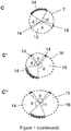
- the contact points have a circular or substantially circular arrangement, preferably so as to surround the acetabulum (13), wherein the angle e defined by two adjacent contact points is never greater than 180°.
- the angle between the line connecting one contact point (4) and the center of the circle best fitting the acetabular rim (7) and the line connecting the adjacent contact point (4) and said center is never greater than 180°.
- Figure 1 A the acetabulum is considered to have a substantially circular shape.
- the glenoid cavity on the other hand, can be considered piriform.
- the glenoid cavity comprises a substantially circular shape on one side, but tapering towards the other side. Therefore, to ensure positional stability of the fixture onto a glenoid cavity (15), the contact points have a circular or substantially circular arrangement around the circumference of the rim of the glenoid cavity. More particularly, the angle ⁇ formed by a first line drawn between one contact point (4) and the center of the circle best fitting the (substantially circular part of) the glenoid cavity rim (16) and a second line drawn between the adjacent contact point (4) and said center is never greater than 180°. This can also be expressed in terms of the sector angle defined by two adjacent contact points (4) which is never greater than 180°. This is shown in Figure 1 A'.
- the glenoid cavity may be considered as having a roughly elliptical shape.
- the contact points have an arrangement, wherein the angle e between the (straight) line connecting one contact point (4) and the center of the ellipse best fitting the glenoid cavity rim (16) and the (straight) line connecting an adjacent contact point (4) and said center is never greater than 180°. Again this can be expressed by the fact that the sector angle defined by two adjacent contact points is never greater than 180°. This is shown in Figure 1 A".
- the contact elements fit onto the socket and/or socket rim by contacting said socket and/or rim at different contact points.
- the contact elements fit onto areas of (or around) a socket and/or a socket rim in at least three contact points, wherein the contact points have an arrangement, preferably so as to surround the socket, wherein the angle between a line drawn between one contact point and the center of the circle or ellipse best fitting the socket rim and a second line drawn between an adjacent contact point and said center is never greater than 180° or similarly the sector angle defined by two adjacent contact points is never greater than 180°.
- These contact points may all be located on the same contact element (i.e. one contact element comprises these three contact points), or distributed over two or more contact elements.
- the one or more contact elements of the surgical fixtures according to the invention contain, on the surface which is intended for placement on the bone (with or without cartilage or other soft tissue), patient-specific surfaces, i.e. anatomy engagement surfaces which at least partially match the surface of (or around) the socket and/or the socket rim.
- patient-specific surfaces i.e. anatomy engagement surfaces which at least partially match the surface of (or around) the socket and/or the socket rim.
- the contact element comprises of a plurality of contact points (corresponding to a contact surface).
- the positional stability of the surgical fixture onto the acetabulum is then at least in part determined by the size and position of the contact surfaces on the contact element(s).
- the patient specific surface of a contact element typically spans an area which varies between one square micrometer ( ⁇ m 2 ) and fifty square centimeters (cm 2 ).
- the surgical fixtures according to the invention comprise only one contact element, which has a single contact surface.
- this contact surface (14) spans the surface of the socket (13) and/or socket rim (7) over an angle q, of at least 180°, as schematically drawn for a circular socket (acetabulum) in Figure 1 B .
- a piriform or elliptical socket (glenoid cavity) imposes a similar requirement ( Figures 1 B' and B").
- the surgical fixtures according to the invention may comprise more than one contact element comprising a patient-specific contact surface.
- a stable positioning of the surgical fixture can then optimally be obtained if the contact surfaces of the different contact elements have an arrangement, on or around the socket (13) and/or socket rim (7), wherein for every pair of adjacent contact points not belonging to the same contact surface (14), the angle q, between the line drawn between one contact point and the center of the circle best fitting the socket rim (7) and a second line drawn between the adjacent contact point and said center is never greater than 180°, as schematically drawn for a circular socket (acetabulum) in Figure 1 C .
- a piriform or elliptical socket imposes a similar requirement ( Figure 1 C' and C").
- fixtures comprising combinations of one or more contact points with one or more contact surfaces are envisaged.
- the surgical fixtures according to the present invention comprise only one contact element, which comprises several patient-specific contact points and/or contact surfaces.
- the surgical fixtures according to the present invention comprise at least two contact elements, each comprising one or more patient-specific contact points and/or surfaces as described hereabove.
- the surgical fixtures according to the present invention comprise three contact elements, each comprising one or more patient-specific contact points and/or surfaces as described hereabove.
- the surgical fixtures according to the present invention comprise four contact elements, each comprising one or more patient-specific contact points and/or surfaces as described hereabove.
- the surgical fixtures according to the present invention comprise (at least) five, six, seven, eight, nine, ten or more contact elements, each comprising one or more patient-specific contact points and/or surfaces as described hereabove.
- the different contact elements of the surgical fixtures of the present invention need not make contact with the bone (with or without cartilage or other soft tissue) in the same way and need not contact the bone over their entire surface.
- at least one contact element contacts, at least partially, the socket rim via its contact point(s) and/or surface(s).
- all contact elements contact, at least partially, the socket rim via the contact point(s) and/or surface(s) comprised therein.
- the position and/or orientation of at least one contact element on the surgical fixture is patient-specific.
- At least one contact element is positioned on the fixture such that its patient-specific surface corresponds to the surface of the corresponding socket in the location of a conspicuous anatomical feature in or around the socket.
- this is for example the posterior notch of the transverse ligament, hereinafter also referred to as "posterior notch”.
- the posterior notch of the transverse ligament (8) of the acetabulum (13) is drawn in Figure 2 A and B .
- this is for example the coracoid process (processus coracoideus); this is a small hook- like structure on the lateral edge of the superior anterior portion of the scapula.
- the fixture of the present invention is provided with a contact element fitting onto and/or into the posterior notch.
- the device can be designed such that, in order to place the contact element within the notch, the surgical fixture according to the invention must be placed on the acetabulum in a first position whereby the contact element is placed next to the posterior notch.
- the desired final position of the surgical fixture onto the acetabulum is then obtained via a (slight) rotational movement of the fixture, which allows the contact element to move over and optionally into the notch until it reaches the rim of the notch.
- the contact between the contact element and the rim of the posterior notch of the transverse ligament ensures a rotational stop when the fixture is in the correct position.
- the fixtures of the invention and more particularly a contact element thereof, may comprise a rotational undercut feature for registering on an anatomical feature around the socket, such as the posterior notch of the transverse ligament, or on top of the coracoid process.
- the surgical fixtures of the invention are designed such that they comprise at least one contact element which interacts with an anatomical feature in the socket, on the socket rim or on the bone (with or without cartilage or other soft tissue) surrounding the socket.
- the socket is a glenoid cavity
- the bone surrounding the socket includes the glenoidal rim and the periglenoidal region (e.g. infraglenoidal tuberculum, supraglenoidal tuberculum and collum scapulae, etc.) and might include the acromion and coracoid process.
- the socket is an acetabulum
- the bone surrounding the socket includes the periacetabular region (e.g.
- the contact element is to be positioned on or within the posterior notch or the coracoid process.
- one contact element is provided on the surgical fixture such that, when correctly positioned on the bone (i.e. in its final position), it fits within or onto the posterior notch or to the location of the coracoid process. More particularly, it is envisaged that, such a contact element grabs or locks onto the posterior notch or the coracoid process. This ensures a strong rotational stop when the fixture is in the correct position and therefore an accurate positioning of the fixture on the socket.
- one contact element and its position on the fixture is such that, when positioned on the bone, it grabs onto or around the anatomical features such as the posterior notch or the coracoid process.
- a contact element may comprise an undercut or may even be hook- shaped, such that it can grab on or around the anatomical feature.
- one contact element comprises an undercut, or comprises a hook-shaped feature. In particular embodiments this undercut specifically mates with the acetabular notch.
- the one or more contact elements are designed such that correct positioning can be ensured by rotation of the contact elements over the rim of the socket.
- a slight rotation of the fixture will ensure that the contact elements fit into the planned position.
- the fixture can be rotated into position despite the fact that the contact elements are rigidly fixed to each other.
- the contact element which interacts with a specific anatomical feature on the rim of the socket or the surrounding bone may further also provide a locking feature.
- the shape of this contact element may be adapted such that, when positioned on the bone, it snaps onto and thus in fact locks onto this feature.
- the surgical fixtures of the present invention allow correct positioning of an alignment element by way of the positioning element.
- the positioning element of the fixtures of the invention comprises an opening or hole which allows the insertion of an alignment element which is guided by the positioning element into the bone surrounding the socket, such as the pelvic bone or scapula.
- the alignment element may be a wire, pin, screw or drill, particularly a metal wire, pin, screw or drill.
- the alignment element is a wire or a pin, particularly a Kirschner wire (K-wire) or a Hoffmann pin.
- the positioning element ensures placement of the alignment feature outside the socket.
- the alignment element is typically positioned on the bone surrounding the socket, for example in the periacetabular area of the acetabulum (e.g. the limbus acetabuli, sulcus supra-acetabularis, superior ramus, etc.) or periglenoidal area of the glenoid cavity (e.g. infraglenoidal tuberculum, supraglenoidal tuberculum and collum scapulae, etc.) of the patient, in a direction parallel to the installation direction of the implant.
- the periacetabular area of the acetabulum e.g. the limbus acetabuli, sulcus supra-acetabularis, superior ramus, etc.
- periglenoidal area of the glenoid cavity e.g. infraglenoidal tuberculum, supraglenoidal tuberculum and collum scapulae, etc.
- the alignment element is typically positioned on the pelvic bone in a direction parallel to the installation direction of the acetabular implant.
- the positioning element ensures placement of the alignment feature inside (typically centrally in) the socket.
- the optimal orientation of the opening of the positioning element can be obtained by determining the orientation of the positioning element according to pre-operational planning.
- the direction and/ or the position of at least one hole of the surgical fixtures of the invention which allows the insertion of an alignment element is in accordance with pre-operational planning. More particularly, this implies that the relative position and/or orientation of least one hole relative to the contact element(s) of the surgical fixtures of the invention is in accordance with pre- operational planning. This allows the use of standard alignment elements such as K- wires.
- the positioning and/or orientation of the hole can be obtained via a certain location and/or orientation of the positioning element relative to the rest of the surgical fixture, via a certain location and/or position of the hole in the positioning element, or via a combination of the two. Additionally or alternatively, the shape of the alignment element itself can be provided such that, when inserted into the positioning element, it ensures the correct orientation to guide the implant.
- the surgical fixtures of the invention may comprise fixation features such as holes, which allow for fixation of the surgical fixtures onto the bone, for example using screws, wires or pins.
- the surgical fixtures of the invention comprise at least one hole in addition to the hole which is meant for insertion of the alignment element.
- the surgical fixtures of the present invention comprise at least two holes.
- the hole(s) used as fixation features and the hole(s) used for insertion of the alignment element are located on the positioning element.
- the hole(s) used as fixation features and the hole(s) used for insertion of the alignment element are cylindrical. As both types of (cylindrical) holes have a different function, they may have a different diameter. The different diameter of the holes also avoids the surgeon from inserting the alignment element into a fixation feature, especially when the fixation features have a smaller diameter than the hole(s) for inserting an alignment element.
- the positioning element and the one or more contact element(s) for positioning on the rim of the socket may be separate units which are detachable. However, when attached, the relative position between the contact element(s), the positioning element and the rest of the fixture is fixed.
- the positioning element is located onto or integrated in a contact element, i.e. the structure comprising the positioning element has a surface which contacts with the bone.
- the contact element is different from the one or more contact elements for placement on the rim of the socket. More particularly, it does not fit onto the rim of the socket but contacts a region outside the socket.
- a positioning element and such a contact element may form a single unit, thus the positioning element may also function as a contact element in that it helps to ensure accurate positioning on the bone.
- the positioning element is integrated into or extends from a contact element on the rim of the socket. Where a positioning element is located onto a contact element on the rim of the socket, the hole(s) in the positioning element continue(s) through the contact element. In this way, the contact element does not block the insertion of fixation elements and/or alignment elements into the bone.
- the contact element(s) onto which a positioning element is located contain at least one hole.
- the positioning of a second, or even a third alignment element allows an even more precise positioning of a socket implant.
- the surgical fixtures according to the present invention comprise more than one positioning element, of which at least one is detachable. In further embodiments, all positioning elements are detachable.
- Insertion of the alignment element and/or fixation elements into the bone may be facilitated by first drilling a hole in the bone.
- the alignment element and/or fixation element(s) are then inserted into the hole drilled in the bone.
- at least one of the openings or holes on the positioning element (and the contact element(s) is part of a drill guide, which is located on the positioning element(s) or the contact element(s).
- the surgical fixture of the invention may be provided with a drill guide which can be positioned onto the hole.
- the surgical fixture according to the present invention is a disk (one contact element) comprising, on the side and/or edges for placement on the bone (with or without cartilage or other soft tissue), one or more contact points and/or contact surface(s) which match (i.e. specifically mate with) areas of (or around) the socket and/or the socket rim as described hereabove; and, on the opposing side of the contact surfaces, a positioning element.
- a less bulky fixture is obtained by omitting certain sectors from the disk, thus creating a surgical fixture containing two or more contact elements with one or more contact points and/or contact surfaces as described above.
- the contact elements may be interconnected by longitudinal structures from a central structure.
- the surgical fixtures according to the present invention comprise a connecting structure, wherein one or more contact elements extend from the connecting structure.
- two or more contact elements extend from the connecting structure.
- the positioning element(s) may extend from the connecting structure.
- the connecting structure is a central element, particularly a central axis.
- the contact element(s) and/or the positioning element(s) are separate units which are connectable to the connecting structure, central element or axis.
- the surgical fixtures of the present invention are manufactured as a single piece.
- the fixture may contain extensions, positioned either on the contact elements and/or a central structure connecting the contact elements.
- the extensions increase grip on the fixture and visibility during the positioning of the fixture on the bone.
- Such extensions can vary in structure such as, but not limited to rod-like structures, hooks, etc.
- the extensions will extend from the fixture structure in a direction which is transversal to the contact surface of the contact elements.
- the fixtures of the invention contain guiding features for guiding surgical instruments.
- guiding features may include a drill bore for guiding a drill to make a hole in the bone for the alignment element.
- additional or alternative guiding elements may also be envisaged, including on one or more of the contact elements and/or a connecting structure (where applicable).
- Such guiding features include holes, slits grooves etc.
- attachment features are provided on one or more parts of the fixture, for fixing additional elements, such as guiding features in a reversible way.
- the surgical fixture must be removed from the socket in order to proceed with the surgery, e.g. to insert the socket implant.
- the inserted alignment element and/or fixation elements
- the present invention provides that in particular embodiments of the surgical fixtures of the invention at least one positioning element on the surgical fixture is detachable. Additionally, it is further envisaged in particular embodiments that one or more contact elements may be detachable.
- the present invention envisages embodiments wherein the connection between the positioning or contact element and the rest of the fixture is adapted or weakened to make the positioning or contact element detachable, while still maintaining the required rigidity to assure correct positioning.
- the connection between at least one positioning element or contact element and the rest of the fixture is adapted and/or weakened such that it can be detached from the guide with surgical cutting instruments.
- this connection is located on an extension of the connecting structure as described hereinabove.
- the one or more positioning elements and/or contact elements may be removably connected to the rest of the fixture via a specific mechanism such as a dovetail coupling, interlocking features, a pinned system, a snap-fit system, or a combination thereof.
- a specific mechanism such as a dovetail coupling, interlocking features, a pinned system, a snap-fit system, or a combination thereof.
- the connection between the positioning element(s) and/or the contact element(s) and the rest of the fixture is a standard connecting feature, the positioning element(s) can be reused on another surgical fixture. In certain embodiments, this connection is located on an extension of the connecting structure as described hereabove.
- the positioning feature (which may itself comprise a contact surface so as to form a contact element) is connected to the remainder of the fixture comprising the one or more contact elements fitting on the rim of the socket by a standard connecting feature such as a dovetail coupling.
- the surgical fixtures of the present invention further comprise one or more extensions on the fixture which do not contain a contact element or positioning element.
- Such extensions as such do not contribute to the fit of the fixture on the bone but may allow an enhanced grip of the surgeon on the surgical fixtures, and may for example facilitate the rotational movement of the surgical fixture during its positioning, or facilitate the removal of the fixture after the positioning of the alignment element.
- such extensions may comprise a screw drive, i.e. a feature that allows the extension (and thus fixture) to be turned with a screw driver, hex key, or the like.
- the screw drive is not positioned on an extension, but elsewhere on the fixture.
- the present invention provides methods for the manufacture of the surgical fixtures described herein.
- the surgical fixtures according to the present invention comprise one or more patient-specific contact points and/or surfaces. Also the relative position and/or orientation of the positioning element(s) and/or the contact elements may be patient-specific.
- the generation of patient-specific surgical fixtures is done based on pre-operative images of the bone area (with or without cartilage or other soft tissue) surrounding the socket of the ball joint under consideration (e.g. the pelvic bone or the scapula), and planning of the surgery. More particularly, the generation of patient- specific surgical fixtures is done based on pre-operative images of the socket (e.g. the acetabulum or the glenoid cavity), and planning of the surgery. Accordingly, methods for producing the surgical fixtures according to the present invention typically comprise the steps of:
- the step of obtaining volume information of the socket typically comprises obtaining digital patient-specific image information which can be done by any suitable means known in the art, such as for example a computer tomography (CT) scanner, a magnetic resonance imaging (MRI) scanner, an ultrasound scanner, or a combination of Roentgenograms.
- CT computer tomography
- MRI magnetic resonance imaging
- ultrasound scanner or a combination of Roentgenograms.
- a summary of medical imaging has been described in " Fundamentals of Medical imaging", by P. Suetens, Cambridge University Press, 2002 .
- AM Additive Manufacturing
- AM techniques are used for manufacturing the surgical fixtures according to the invention, or parts thereof.
- AM techniques are particularly useful to manufacture patient-specific contact surfaces, or to produce the surgical fixtures in one piece.
- the manufacturing of medical-image-based patient-specific surgical instruments via AM is described in US Pat. No. 5.768.134 (Swaelens et al ).
- AM can be defined as a group of techniques used to fabricate a tangible model of an object typically using three-dimensional (3-D) computer aided design (CAD) data of the object.
- 3-D three-dimensional
- CAD computer aided design
- Additive Manufacturing techniques including stereolithography, Selective Laser Sintering, Fused Deposition Modeling, foil- based techniques, etc.
- Selective laser sintering uses a high power laser or another focused heat source to sinter or weld small particles of plastic, metal, or ceramic powders into a mass representing the 3-dimensional object to be formed.
- Fused deposition modeling and related techniques make use of a temporary transition from a solid material to a liquid state, usually due to heating.
- the material is driven through an extrusion nozzle in a controlled way and deposited in the required place as described among others in U.S. Pat. No. 5.141.680 .
- Foil-based techniques fix coats to one another by means of gluing or photo polymerization or other techniques and cut the object from these coats or polymerize the object. Such a technique is described in U.S. Pat. No. 5.192.539 .
- AM techniques start from a digital representation of the 3-D object to be formed.
- the digital representation is sliced into a series of cross-sectional layers which can be overlaid to form the object as a whole.
- the AM apparatus uses this data for building the object on a layer-by-layer basis.
- the cross-sectional data representing the layer data of the 3-D object may be generated using a computer system and computer aided design and manufacturing (CAD/CAM) software.
- CAD/CAM computer aided design and manufacturing
- the surgical fixtures according to the present invention may be manufactured in different materials. Typically, only materials that are biocompatible (e.g. USP class VI compatible) with the animal or human body are taken into account.
- the surgical fixture is formed from a heat-tolerable material allowing it to tolerate high- temperature sterilization.
- the surgical template may be fabricated from a polyamide such as PA 2200 as supplied by EOS, Kunststoff, Germany or any other material known by those skilled in the art may also be used.
- a further aspect of the present invention provides methods for using the surgical fixtures described herein. More particularly, the present invention provides methods for guiding an implant in a socket of a ball joint such as an acetabulum or glenoid cavity. The methods comprise the steps of:
- step 1 involves a rotational movement of the fixture to obtain the desired orientation onto the socket in such a way that the contact element which interacts with an anatomical feature on the rim of the socket is fitted into place.
- the rotational movement of the contact elements will allow the undercut or hook of the contact element to be tightly fixed onto an anatomical feature. More particularly for fixtures on the acetabulum, the placement of the fixture is envisaged to involve the fixing of the rotational undercut of a contact element of the device onto the posterior notch of the transverse ligament.
- step 4 will comprise detaching said positioning element from the rest of the fixture and from the socket, so as to allow thereafter, a reversal of the rotational movement of step 1 to remove the rest of the fixture from the socket.
- this is ensured by releasing the coupling feature of the positioning element (e.g. dovetail).
- this is ensured by breaking the connection between the positioning element and the rest of the fixture.
- the alignment element envisaged in the context of the present invention may be used as a visual alignment element or a physical alignment element.
- the alignment element is a pin or wire and is used as a physical alignment element to guide an implant or implant guide onto the bone in the correct position.
- the implant or implant guide will comprise a hole or slit which is positioned such that, when the hole or slit of the implant or implant guide is mated with the alignment feature, it will guide the implant and/or implant guide directly in the desired position on the socket of the ball joint.
- Example 1 surgical fixture with multiple contact elements.
- the surgical fixtures according to the present invention may comprise more than one contact element.
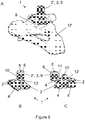
- Figure 3 A shows such a surgical fixture (1) according to a particular embodiment of the present invention, positioned onto the acetabulum of a pelvic bone (17), more particularly the pelvic bone of Figure 2 B .
- Figures 3 B and C show two views of the same fixture, not positioned on a bone.
- the fixture comprises a positioning element (3) and four contact elements (2, 2'), each comprising a patient-specific contact surface (4).
- One of the contact surfaces (4') is designed to register onto the posterior notch of the transverse ligament (8), thereby providing a rotational undercut and a rotational lock. This facilitates the correct positioning of the fixture onto the acetabulum.
- the positioning element forms a single unit with one of the contact elements (2'), and comprises a hole (5) for insertion of an alignment element and holes (6) for insertion of fixation elements.
- the hole (5) for insertion of an alignment element may also be used for drilling a hole in the pelvic bone.
- the positioning element is also a drill guide (9), more particularly a drilling cylinder.
- Each of the contact elements (2, 2') extends from a connecting structure (12).
- the connection (11) between the positioning element (3) and the connecting structure (12) is adapted, such that the positioning element can be easily detached from the surgical fixture with surgical cutting instruments.
- the surgical fixture (1) further comprises an additional extension (10), which allows for an enhanced grip on the fixture.
- the extension (10) is further provided with an identification code, for example a patient identifier.
- Figure 3 D shows a similar fixture as shown in Figures 3A-C , wherein the extention (10) is not provided with an identification code.
- Example 2 surgical fixture with one contact element.
- the surgical fixtures according to the present invention may comprise only one contact element.
- Figure 4 A shows such a surgical fixture (1) according to a particular embodiment of the present invention.
- the fixture comprises a positioning element (3) and one contact element (2).
- the contact element comprises a patient-specific contact surface (4).
- the positioning element is attached to the contact element (2), and comprises a hole (5) for insertion of an alignment element and holes (6) for insertion of fixation elements.
- the hole (5) for insertion of an alignment element may also be used for drilling a hole in the pelvic bone.
- the positioning element is also a drill guide (9), more particularly a drilling cylinder.
- the connection between the positioning element (3) and the contact element (2) is adapted (not shown), such that the positioning element can be easily detached from the surgical fixture with surgical cutting instruments.
- the surgical fixture (1) further comprises two extensions (10), which are located on the contact element (2) and facilitate the rotational movement of the fixture during positioning.
- Figure 4 B shows the same fixture (1), positioned on an acetabulum of a pelvic bone (17).
- the contact surface on the contact element of the fixture surrounds the acetabulum over an angle of more than 180°.
- Example 3 surgical fixture providing rotational lock.
- Figure 5 A shows a surgical fixture (1) according to a particular embodiment of the present invention, positioned onto the acetabulum of a pelvic bone (17), more particularly the pelvic bone of Figure 2 B .
- Figures 5 Band C show two views of the same fixture, not positioned on a bone.
- the fixture comprises a positioning element (3) and four contact elements (2, 2'), each comprising a patient-specific contact surface (4, 4').
- Each of the contact elements (2, 2') extends from a connecting structure (12).
- One of the contact surfaces (4') is designed to register onto the posterior notch of the transverse ligament (8). More particularly, the contact surface (4') is designed to partially surround the posterior notch (8), thereby providing a rotational undercut and a strong rotational lock.
- the positioning element forms a single unit with one of the contact elements (2'), and comprises a hole (5) for insertion of an alignment element and holes (6) for insertion of fixation elements.
- the hole (5) for insertion of an alignment element may also be used for drilling a hole in the pelvic bone.
- the positioning element is also a drill guide (9), more particularly a drilling cylinder.
- the connection (11) between the positioning element (3) and the connecting structure (12) is adapted, such that the positioning element can be easily detached from the surgical fixture with surgical cutting instruments.
- the contact element (2') which forms a single unit with the positioning element (3) has a contact surface (4) which fits a part of the acetabular rim (7), but does not provide a rotational lock, as this would potentially impede the removal of the detached positioning element (3) from the acetabulum.
- the surgical fixture (1) further comprises an additional extension (10), which allows for an enhanced grip on the fixture.
Landscapes
- Health & Medical Sciences (AREA)
- Life Sciences & Earth Sciences (AREA)
- Orthopedic Medicine & Surgery (AREA)
- Surgery (AREA)
- General Health & Medical Sciences (AREA)
- Veterinary Medicine (AREA)
- Engineering & Computer Science (AREA)
- Biomedical Technology (AREA)
- Heart & Thoracic Surgery (AREA)
- Transplantation (AREA)
- Animal Behavior & Ethology (AREA)
- Oral & Maxillofacial Surgery (AREA)
- Public Health (AREA)
- Nuclear Medicine, Radiotherapy & Molecular Imaging (AREA)
- Medical Informatics (AREA)
- Molecular Biology (AREA)
- Physical Education & Sports Medicine (AREA)
- Cardiology (AREA)
- Vascular Medicine (AREA)
- Dentistry (AREA)
- Biophysics (AREA)
- Pathology (AREA)
- Prostheses (AREA)
- Surgical Instruments (AREA)
Applications Claiming Priority (4)
| Application Number | Priority Date | Filing Date | Title |
|---|---|---|---|
| US13/180,688 US10092419B2 (en) | 2011-07-12 | 2011-07-12 | Surgical instrument for the positioning of an alignment element |
| EP11173606 | 2011-07-12 | ||
| EP12740926.6A EP2731512B1 (de) | 2011-07-12 | 2012-07-12 | Verfahren zur herstellung eines chirurgischen instruments zur positionierung eines ausrichtungselements |
| PCT/EP2012/063676 WO2013007785A1 (en) | 2011-07-12 | 2012-07-12 | Surgical instrument for the positioning of an alignment element |
Related Parent Applications (2)
| Application Number | Title | Priority Date | Filing Date |
|---|---|---|---|
| EP12740926.6A Division EP2731512B1 (de) | 2011-07-12 | 2012-07-12 | Verfahren zur herstellung eines chirurgischen instruments zur positionierung eines ausrichtungselements |
| EP12740926.6A Division-Into EP2731512B1 (de) | 2011-07-12 | 2012-07-12 | Verfahren zur herstellung eines chirurgischen instruments zur positionierung eines ausrichtungselements |
Publications (1)
| Publication Number | Publication Date |
|---|---|
| EP3760142A1 true EP3760142A1 (de) | 2021-01-06 |
Family
ID=49918985
Family Applications (2)
| Application Number | Title | Priority Date | Filing Date |
|---|---|---|---|
| EP20187534.1A Pending EP3760142A1 (de) | 2011-07-12 | 2012-07-12 | Chirurgische vorrichtung zum positionieren eines ausrichtungselements |
| EP12740926.6A Active EP2731512B1 (de) | 2011-07-12 | 2012-07-12 | Verfahren zur herstellung eines chirurgischen instruments zur positionierung eines ausrichtungselements |
Family Applications After (1)
| Application Number | Title | Priority Date | Filing Date |
|---|---|---|---|
| EP12740926.6A Active EP2731512B1 (de) | 2011-07-12 | 2012-07-12 | Verfahren zur herstellung eines chirurgischen instruments zur positionierung eines ausrichtungselements |
Country Status (3)
| Country | Link |
|---|---|
| EP (2) | EP3760142A1 (de) |
| JP (1) | JP6133284B2 (de) |
| AU (1) | AU2012282519B2 (de) |
Cited By (2)
| Publication number | Priority date | Publication date | Assignee | Title |
|---|---|---|---|---|
| US12070272B2 (en) | 2013-10-10 | 2024-08-27 | Stryker European Operations Limited | Methods, systems and devices for pre-operatively planned shoulder surgery guides and implants |
| US12097129B2 (en) | 2021-10-20 | 2024-09-24 | Tornier Sas | Shoulder patient specific instrument |
Families Citing this family (2)
| Publication number | Priority date | Publication date | Assignee | Title |
|---|---|---|---|---|
| JP6933828B2 (ja) * | 2017-07-27 | 2021-09-08 | 国立大学法人大阪大学 | 寛骨臼回転骨切り術用の手術器具 |
| KR101981055B1 (ko) * | 2017-08-31 | 2019-05-23 | 주식회사 코렌텍 | 환자 맞춤형 수술기기 제조 시스템 및 그 방법 |
Citations (12)
| Publication number | Priority date | Publication date | Assignee | Title |
|---|---|---|---|---|
| US5141680A (en) | 1988-04-18 | 1992-08-25 | 3D Systems, Inc. | Thermal stereolighography |
| US5192539A (en) | 1988-07-21 | 1993-03-09 | Akzo N.V. | Infectious bursal disease virus production in continuous cell lines |
| US5768134A (en) | 1994-04-19 | 1998-06-16 | Materialise, Naamloze Vennootschap | Method for making a perfected medical model on the basis of digital image information of a part of the body |
| US5976149A (en) * | 1997-02-11 | 1999-11-02 | Medidea, Llc | Method and apparatus for aligning a prosthetic element |
| US20060161167A1 (en) * | 2005-01-18 | 2006-07-20 | Reese Myers | Acetabular instrument alignment guide |
| US20090163922A1 (en) | 2006-02-27 | 2009-06-25 | Biomet Manufacturing Corp. | Patient Specific Acetabular Guide And Method |
| US20100016984A1 (en) * | 2008-07-21 | 2010-01-21 | Harutaro Trabish | Acetabulum Surgical Resurfacing Aid |
| US20100082035A1 (en) | 2008-09-30 | 2010-04-01 | Ryan Keefer | Customized patient-specific acetabular orthopaedic surgical instrument and method of use and fabrication |
| US20100087829A1 (en) * | 2006-02-27 | 2010-04-08 | Biomet Manufacturing Corp. | Patient Specific Alignment Guide With Cutting Surface and Laser Indicator |
| WO2010124164A1 (en) * | 2009-04-23 | 2010-10-28 | Ure Keith J | A device and method for achieving accurate positioning of acetabular cup during total hip replacement |
| WO2011029911A1 (en) * | 2009-09-11 | 2011-03-17 | Materialise N.V. | Adaptable therapeutic, diagnostic or surgical guide |
| WO2011060536A1 (en) | 2009-11-17 | 2011-05-26 | Queen's University At Kingston | Patient-specific guide for acetabular cup placement |
Family Cites Families (4)
| Publication number | Priority date | Publication date | Assignee | Title |
|---|---|---|---|---|
| FR2681238A1 (fr) * | 1991-09-13 | 1993-03-19 | Impact | Cotyle pour prothese de hanche. |
| FR2819172B3 (fr) * | 2001-01-08 | 2003-01-31 | Groupe Lepine | Implant cotyloidien dit "de reprise" |
| US7542791B2 (en) * | 2003-01-30 | 2009-06-02 | Medtronic Navigation, Inc. | Method and apparatus for preplanning a surgical procedure |
| US8568487B2 (en) * | 2006-02-27 | 2013-10-29 | Biomet Manufacturing, Llc | Patient-specific hip joint devices |
-
2012
- 2012-07-12 JP JP2014519559A patent/JP6133284B2/ja active Active
- 2012-07-12 EP EP20187534.1A patent/EP3760142A1/de active Pending
- 2012-07-12 EP EP12740926.6A patent/EP2731512B1/de active Active
- 2012-07-12 AU AU2012282519A patent/AU2012282519B2/en active Active
Patent Citations (12)
| Publication number | Priority date | Publication date | Assignee | Title |
|---|---|---|---|---|
| US5141680A (en) | 1988-04-18 | 1992-08-25 | 3D Systems, Inc. | Thermal stereolighography |
| US5192539A (en) | 1988-07-21 | 1993-03-09 | Akzo N.V. | Infectious bursal disease virus production in continuous cell lines |
| US5768134A (en) | 1994-04-19 | 1998-06-16 | Materialise, Naamloze Vennootschap | Method for making a perfected medical model on the basis of digital image information of a part of the body |
| US5976149A (en) * | 1997-02-11 | 1999-11-02 | Medidea, Llc | Method and apparatus for aligning a prosthetic element |
| US20060161167A1 (en) * | 2005-01-18 | 2006-07-20 | Reese Myers | Acetabular instrument alignment guide |
| US20090163922A1 (en) | 2006-02-27 | 2009-06-25 | Biomet Manufacturing Corp. | Patient Specific Acetabular Guide And Method |
| US20100087829A1 (en) * | 2006-02-27 | 2010-04-08 | Biomet Manufacturing Corp. | Patient Specific Alignment Guide With Cutting Surface and Laser Indicator |
| US20100016984A1 (en) * | 2008-07-21 | 2010-01-21 | Harutaro Trabish | Acetabulum Surgical Resurfacing Aid |
| US20100082035A1 (en) | 2008-09-30 | 2010-04-01 | Ryan Keefer | Customized patient-specific acetabular orthopaedic surgical instrument and method of use and fabrication |
| WO2010124164A1 (en) * | 2009-04-23 | 2010-10-28 | Ure Keith J | A device and method for achieving accurate positioning of acetabular cup during total hip replacement |
| WO2011029911A1 (en) * | 2009-09-11 | 2011-03-17 | Materialise N.V. | Adaptable therapeutic, diagnostic or surgical guide |
| WO2011060536A1 (en) | 2009-11-17 | 2011-05-26 | Queen's University At Kingston | Patient-specific guide for acetabular cup placement |
Non-Patent Citations (3)
| Title |
|---|
| HAYAKAWA ET AL., ARCHIVES OF ORTHOPEDIC AND TRAUMA SURGERY, vol. 129, 2009, pages 1151 - 1156 |
| P. SUETENS: "Fundamentals of Medical imaging", 2002, CAMBRIDGE UNIVERSITY PRESS |
| PEARSE ET AL., HIP INTERNATIONAL, vol. 18, 2008, pages 7 - 10 |
Cited By (2)
| Publication number | Priority date | Publication date | Assignee | Title |
|---|---|---|---|---|
| US12070272B2 (en) | 2013-10-10 | 2024-08-27 | Stryker European Operations Limited | Methods, systems and devices for pre-operatively planned shoulder surgery guides and implants |
| US12097129B2 (en) | 2021-10-20 | 2024-09-24 | Tornier Sas | Shoulder patient specific instrument |
Also Published As
| Publication number | Publication date |
|---|---|
| EP2731512A1 (de) | 2014-05-21 |
| JP2014526917A (ja) | 2014-10-09 |
| AU2012282519A1 (en) | 2014-01-16 |
| EP2731512B1 (de) | 2020-10-07 |
| JP6133284B2 (ja) | 2017-05-24 |
| AU2012282519B2 (en) | 2017-01-12 |
Similar Documents
| Publication | Publication Date | Title |
|---|---|---|
| US10092419B2 (en) | Surgical instrument for the positioning of an alignment element | |
| US20140142578A1 (en) | Surgical instrument for the positioning of an alignment element | |
| EP3248553B1 (de) | Schulterführungen | |
| US9198760B2 (en) | Guiding instruments and impactors for an acetabular cup implant, combinations thereof, methods for manufacturing and uses thereof | |
| US10052114B2 (en) | Shoulder base plate coverage and stability | |
| EP2670314B1 (de) | Abdeckung und stabilisierung einer schulterplatte | |
| EP2757978B1 (de) | Patientenspezifische chirurgische führung | |
| EP2575643B1 (de) | Führung für acetabulumfräser | |
| US20200046381A1 (en) | Patient-specific glenoid guides | |
| US20160228132A1 (en) | Patient-specific glenoid guides | |
| WO2014093435A1 (en) | Patient-specific acetabular guide for anterior approach | |
| EP2731512B1 (de) | Verfahren zur herstellung eines chirurgischen instruments zur positionierung eines ausrichtungselements |
Legal Events
| Date | Code | Title | Description |
|---|---|---|---|
| PUAI | Public reference made under article 153(3) epc to a published international application that has entered the european phase |
Free format text: ORIGINAL CODE: 0009012 |
|
| STAA | Information on the status of an ep patent application or granted ep patent |
Free format text: STATUS: THE APPLICATION HAS BEEN PUBLISHED |
|
| AC | Divisional application: reference to earlier application |
Ref document number: 2731512 Country of ref document: EP Kind code of ref document: P |
|
| AK | Designated contracting states |
Kind code of ref document: A1 Designated state(s): AL AT BE BG CH CY CZ DE DK EE ES FI FR GB GR HR HU IE IS IT LI LT LU LV MC MK MT NL NO PL PT RO RS SE SI SK SM TR |
|
| STAA | Information on the status of an ep patent application or granted ep patent |
Free format text: STATUS: REQUEST FOR EXAMINATION WAS MADE |
|
| 17P | Request for examination filed |
Effective date: 20210706 |
|
| RBV | Designated contracting states (corrected) |
Designated state(s): AL AT BE BG CH CY CZ DE DK EE ES FI FR GB GR HR HU IE IS IT LI LT LU LV MC MK MT NL NO PL PT RO RS SE SI SK SM TR |
|
| RAP3 | Party data changed (applicant data changed or rights of an application transferred) |
Owner name: MATERIALISE NV |
|
| STAA | Information on the status of an ep patent application or granted ep patent |
Free format text: STATUS: EXAMINATION IS IN PROGRESS |
|
| 17Q | First examination report despatched |
Effective date: 20230524 |
|
| GRAP | Despatch of communication of intention to grant a patent |
Free format text: ORIGINAL CODE: EPIDOSNIGR1 |
|
| STAA | Information on the status of an ep patent application or granted ep patent |
Free format text: STATUS: GRANT OF PATENT IS INTENDED |
|
| RIC1 | Information provided on ipc code assigned before grant |
Ipc: A61F 2/30 20060101ALN20240208BHEP Ipc: A61B 34/10 20160101ALN20240208BHEP Ipc: A61B 17/56 20060101ALN20240208BHEP Ipc: A61B 90/11 20160101ALI20240208BHEP Ipc: A61F 2/46 20060101ALI20240208BHEP Ipc: A61B 17/17 20060101AFI20240208BHEP |
|
| INTG | Intention to grant announced |
Effective date: 20240221 |
|
| GRAJ | Information related to disapproval of communication of intention to grant by the applicant or resumption of examination proceedings by the epo deleted |
Free format text: ORIGINAL CODE: EPIDOSDIGR1 |
|
| STAA | Information on the status of an ep patent application or granted ep patent |
Free format text: STATUS: EXAMINATION IS IN PROGRESS |
|
| GRAP | Despatch of communication of intention to grant a patent |
Free format text: ORIGINAL CODE: EPIDOSNIGR1 |
|
| STAA | Information on the status of an ep patent application or granted ep patent |
Free format text: STATUS: GRANT OF PATENT IS INTENDED |
|
| INTG | Intention to grant announced |
Effective date: 20240704 |
|
| RIC1 | Information provided on ipc code assigned before grant |
Ipc: A61F 2/30 20060101ALN20240621BHEP Ipc: A61B 34/10 20160101ALN20240621BHEP Ipc: A61B 17/56 20060101ALN20240621BHEP Ipc: A61B 90/11 20160101ALI20240621BHEP Ipc: A61F 2/46 20060101ALI20240621BHEP Ipc: A61B 17/17 20060101AFI20240621BHEP |