EP3760087B1 - Meat grill installation - Google Patents
Meat grill installation Download PDFInfo
- Publication number
- EP3760087B1 EP3760087B1 EP20182006.5A EP20182006A EP3760087B1 EP 3760087 B1 EP3760087 B1 EP 3760087B1 EP 20182006 A EP20182006 A EP 20182006A EP 3760087 B1 EP3760087 B1 EP 3760087B1
- Authority
- EP
- European Patent Office
- Prior art keywords
- meat
- cylindrical element
- grill installation
- installation according
- heaters
- Prior art date
- Legal status (The legal status is an assumption and is not a legal conclusion. Google has not performed a legal analysis and makes no representation as to the accuracy of the status listed.)
- Active
Links
- 235000013372 meat Nutrition 0.000 title claims description 156
- 238000009434 installation Methods 0.000 title claims description 57
- 238000005520 cutting process Methods 0.000 claims description 37
- 238000000034 method Methods 0.000 claims description 20
- XLYOFNOQVPJJNP-UHFFFAOYSA-N water Substances O XLYOFNOQVPJJNP-UHFFFAOYSA-N 0.000 claims description 13
- 238000010438 heat treatment Methods 0.000 claims description 12
- 239000012190 activator Substances 0.000 claims description 7
- 230000005855 radiation Effects 0.000 claims description 7
- 241000826860 Trapezium Species 0.000 claims description 5
- 238000010411 cooking Methods 0.000 description 8
- 230000001276 controlling effect Effects 0.000 description 6
- 235000018102 proteins Nutrition 0.000 description 6
- 108090000623 proteins and genes Proteins 0.000 description 6
- 102000004169 proteins and genes Human genes 0.000 description 6
- 108010064851 Plant Proteins Proteins 0.000 description 3
- 235000021118 plant-derived protein Nutrition 0.000 description 3
- 230000001105 regulatory effect Effects 0.000 description 3
- 238000003860 storage Methods 0.000 description 3
- 241000251468 Actinopterygii Species 0.000 description 2
- 239000004215 Carbon black (E152) Substances 0.000 description 2
- 241000287828 Gallus gallus Species 0.000 description 2
- 108010060231 Insect Proteins Proteins 0.000 description 2
- 235000019687 Lamb Nutrition 0.000 description 2
- 235000015278 beef Nutrition 0.000 description 2
- 239000000919 ceramic Substances 0.000 description 2
- 235000013330 chicken meat Nutrition 0.000 description 2
- 235000019688 fish Nutrition 0.000 description 2
- 229930195733 hydrocarbon Natural products 0.000 description 2
- 150000002430 hydrocarbons Chemical class 0.000 description 2
- VNWKTOKETHGBQD-UHFFFAOYSA-N methane Chemical compound C VNWKTOKETHGBQD-UHFFFAOYSA-N 0.000 description 2
- 230000000813 microbial effect Effects 0.000 description 2
- 238000005192 partition Methods 0.000 description 2
- 230000035515 penetration Effects 0.000 description 2
- 235000015277 pork Nutrition 0.000 description 2
- 241000894006 Bacteria Species 0.000 description 1
- 241000233866 Fungi Species 0.000 description 1
- 238000005266 casting Methods 0.000 description 1
- 238000000354 decomposition reaction Methods 0.000 description 1
- 230000003247 decreasing effect Effects 0.000 description 1
- 238000001035 drying Methods 0.000 description 1
- 230000005670 electromagnetic radiation Effects 0.000 description 1
- 238000001704 evaporation Methods 0.000 description 1
- 230000008020 evaporation Effects 0.000 description 1
- 239000000796 flavoring agent Substances 0.000 description 1
- 235000019634 flavors Nutrition 0.000 description 1
- 235000013305 food Nutrition 0.000 description 1
- 238000000338 in vitro Methods 0.000 description 1
- 208000015181 infectious disease Diseases 0.000 description 1
- 238000003780 insertion Methods 0.000 description 1
- 230000037431 insertion Effects 0.000 description 1
- 239000000203 mixture Substances 0.000 description 1
- 235000013550 pizza Nutrition 0.000 description 1
- 238000002360 preparation method Methods 0.000 description 1
- 235000020991 processed meat Nutrition 0.000 description 1
- 239000007787 solid Substances 0.000 description 1
- 230000001960 triggered effect Effects 0.000 description 1
- 230000000007 visual effect Effects 0.000 description 1
Images


Classifications
-
- A—HUMAN NECESSITIES
- A47—FURNITURE; DOMESTIC ARTICLES OR APPLIANCES; COFFEE MILLS; SPICE MILLS; SUCTION CLEANERS IN GENERAL
- A47J—KITCHEN EQUIPMENT; COFFEE MILLS; SPICE MILLS; APPARATUS FOR MAKING BEVERAGES
- A47J37/00—Baking; Roasting; Grilling; Frying
- A47J37/04—Roasting apparatus with movably-mounted food supports or with movable heating implements; Spits
- A47J37/044—Roasting apparatus with movably-mounted food supports or with movable heating implements; Spits with conveyors moving in a horizontal or an inclined plane
-
- A—HUMAN NECESSITIES
- A47—FURNITURE; DOMESTIC ARTICLES OR APPLIANCES; COFFEE MILLS; SPICE MILLS; SUCTION CLEANERS IN GENERAL
- A47J—KITCHEN EQUIPMENT; COFFEE MILLS; SPICE MILLS; APPARATUS FOR MAKING BEVERAGES
- A47J37/00—Baking; Roasting; Grilling; Frying
- A47J37/04—Roasting apparatus with movably-mounted food supports or with movable heating implements; Spits
- A47J37/042—Roasting apparatus with movably-mounted food supports or with movable heating implements; Spits with food supports arranged on wheels or spiders rotating about a horizontal axis
-
- A—HUMAN NECESSITIES
- A22—BUTCHERING; MEAT TREATMENT; PROCESSING POULTRY OR FISH
- A22C—PROCESSING MEAT, POULTRY, OR FISH
- A22C17/00—Other devices for processing meat or bones
- A22C17/0006—Cutting or shaping meat
- A22C17/0033—Cutting slices out of a piece of meat
-
- A—HUMAN NECESSITIES
- A47—FURNITURE; DOMESTIC ARTICLES OR APPLIANCES; COFFEE MILLS; SPICE MILLS; SUCTION CLEANERS IN GENERAL
- A47J—KITCHEN EQUIPMENT; COFFEE MILLS; SPICE MILLS; APPARATUS FOR MAKING BEVERAGES
- A47J37/00—Baking; Roasting; Grilling; Frying
- A47J37/04—Roasting apparatus with movably-mounted food supports or with movable heating implements; Spits
- A47J37/041—Roasting apparatus with movably-mounted food supports or with movable heating implements; Spits with food supports rotating about a horizontal axis
-
- A—HUMAN NECESSITIES
- A47—FURNITURE; DOMESTIC ARTICLES OR APPLIANCES; COFFEE MILLS; SPICE MILLS; SUCTION CLEANERS IN GENERAL
- A47J—KITCHEN EQUIPMENT; COFFEE MILLS; SPICE MILLS; APPARATUS FOR MAKING BEVERAGES
- A47J37/00—Baking; Roasting; Grilling; Frying
- A47J37/04—Roasting apparatus with movably-mounted food supports or with movable heating implements; Spits
- A47J37/045—Roasting apparatus with movably-mounted food supports or with movable heating implements; Spits with endless conveyors
Definitions
- the present invention is in the field of a meat grill installation for preparing large quantities of meat, and a method of preparing such large quantities of meat.
- meat may be prepared by heating in an oven, in a stove or in a pan, to a temperature sufficient to cook the meat.
- Meat may be fully cooked or partly cooked.
- Meat comprises water, protein, and fat. It may be eaten raw, but normally it is cooked and often seasoned as well. Unprocessed meat may have health risks due to infection with and decomposition by bacteria and fungi. It is therefore best cooled, or frozen, and thereafter processed quickly.
- the present invention therefore relates to a meat grill installation and a method for heating frozen meat, which solves one or more of the above problems and drawbacks of the prior art, providing reliable results, without jeopardizing functionality and advantages.
- the present invention relates to a meat grill installation comprising a detachable horizontal cylindrical carrier, hereinafter referred to as a cylindrical element for carrying meat, typically a large quantity of meat.
- the cylindrical element comprises a series of meat fixators at its boundary. It further comprises a motor for rotating the cylindrical element around its horizontal axis.
- the horizontal axis may be slightly tilted.
- Further motors may be present, or combined, such as for driving a conveyor belt, for driving adaptable supports, for rotating a cutter, hereinafter named a cutting element, for driving position adapters, etc.
- Heaters are typically provided at a substantially equal distance from the centre of the cylindrical element and are typically rotated, that is to say tilted, such that a heating part thereof faces the to be heated meat as much as possible.
- a length of each heater is individually adapted to a length of the cylindrical element, typically being more or less ( ⁇ 5%) the same length. Therewith the heaters are adapted to heat the meat evenly and as thorough as required.
- It further comprises at least two position adapters for maintaining each individual heater at a predetermined distance from the cylindrical element. Therewith the speed of heating is controlled.
- position adapters are provided to maintain the heaters at a substantially similar distance from the meat over time.
- at least one sensor is provided, preferably at least two sensors, for determining a temperature of the heated meat. The sensed temperature can be used to increase or decrease the distance of the heaters with respect to the meat, to increase or decrease the temperature of the heaters, to increase or decrease a rotation velocity of the cylindrical element, or maintain these variables, or a combination thereof.
- a conveyer belt is provided located underneath the cylindrical element for receiving and transporting heated meat.
- the conveyor belt typically moves in operation in a direction parallel to the longitudinal axis of the cylindrical element.
- a cutting element is provided for removing a slice of a predetermined thickness of meat from the detachable cylindrical element, which typically moves in operation in the same or opposite direction as the conveyor belt.
- the thickness may be varied by tilting the cutting element and/or adjusting the vertical position thereof.
- the width may be varied by providing a wider or smaller cutting element, and the length may be varied by increasing or decreasing a speed of the cutting element and a length of a path travelled by the cutting element, or a combination thereof.
- At least one controller is provided for driving the motor, for maintaining and/or adapting a temperature of each individual heater, for driving the at least two position adapters, for receiving the sensor output, for providing feedback to at least one heater, and for controlling thickness of slices of meat, and combinations thereof.
- the installation may be provided on a frame, and further security measures may be present, such as a fencing.
- controls are typically provided, such as start and stop buttons.
- software may be provided for controlling the installation, typically loaded on a storage medium and provided as a processor. Therewith large quantities of meat can be processed in a well-controlled manner in a relatively short time.
- the present invention relates to a method of heating 100-3000 kg of frozen meat, comprising providing a cylindrical element provided with meat, and the at least one diaphragm opened, moving the cylindrical element into the meat grill installation of the present invention, heating the meat, and cutting at least one slice of meat.
- the present invention provides a solution to one or more of the above-mentioned problems and drawbacks.
- the present invention relates in a first aspect to an installation according to claim 1.
- the present meat grill installation may further comprise at least three in height adaptable supports, wherein the height of the supports is controlled by the at least one controller, and wherein the conveyor belt, at least one sensor, and cutting element are attached to the at least three supports.
- the present meat grill installation may further comprise at least one water supply, preferably at least one water supply at each side, for adapting a water content of the meat, and/or comprising at least one steam supply 56, preferably at least one steam supply at each side, for adapting a temperature of the meat.
- These supplies are typically directed towards the to be processed meat, i.e. in a direction parallel to a radius of the cylindrical element
- the cylindrical element may comprise two diaphragms, one at either side thereof, for enclosing meat, which diaphragms are adapted to at least partly open and close. Such as under the influence of escaping gasses, such as steam, during the heating of the meat.
- the cylindrical element may be adapted to be maintained at a fixed height.
- the supports may be mutually connected by a connector, such as a chain.
- the at least one controller may drive the connector and thereby the height of the supports.
- the supports may comprise a worm gear, and a gear adapted to be driven by the connector.
- the conveyor belt may be an endless conveyor belt.
- the horizontal speed of the cutting element and conveyor belt may be adapted to one and another.
- the cutting element may be adapted to be driven back and forth.
- the present meat grill installation may further comprise a shuttle in connection with the cutting element, wherein the shuttle is adapted for forward movement and backward movement, wherein during forward movement the shuttle tilts and fixes the cutting element in a forward angle of 5-35 degrees, such as 10-30 degrees, e.g. 20-25 degrees, with respect to the horizontal plane, and wherein during backward movement the shuttle tilts and fixes the cutting element in a backward angle of minus 5-35 degrees, such as 10-30 degrees, e.g. 20-25 degrees, with respect to the horizontal plane, wherein tilting is preferably provided by at least one tilt activator 66, such as a notch.
- the shuttle is adapted for forward movement and backward movement, wherein during forward movement the shuttle tilts and fixes the cutting element in a forward angle of 5-35 degrees, such as 10-30 degrees, e.g. 20-25 degrees, with respect to the horizontal plane, and wherein during backward movement the shuttle tilts and fixes the cutting element in a backward angle of minus 5-35 degrees, such as 10-30 degrees, e.
- the cutting element may be a rotating disc provided with a sharp edge.
- the rotating disc may have a diameter of 10-300 mm, such as 20-150 mm, and may rotate with a speed of 100-6000 rpm, preferably 200-1000 rpm, such as 300-600 rpm.
- the present meat grill installation may further comprise a hydrocarbon gas supply, and wherein the at least one heater is a gas heater, such as ceramic gas heater.
- the hydrocarbon gas may be methane.
- the senor may be an Infrared sensor.
- the cylindrical element may comprise an alarm, such as an audio and/or visual alarm.
- an alarm such as an audio and/or visual alarm.
- the alarm is triggered when, is use, a meat temperature is detected below a minimum desired cooking temperature and/or when, in use, a meat temperature is detected above a maximum desired cooking temperature.
- the series of meat fixators may comprise 2-30 spikes, such as 5-20 spikes.
- the cylindrical element may comprise at least two uptake elements 13 per meat fixator, such as 3-6 uptake elements, such as trapezium shaped uptake elements provided with an opening therein.
- uptake elements, and spikes are well fixed and can carry the weight of the meat.
- the cylindrical element may comprise at least four recesses 14 provided along a longitudinal axis of the cylindrical element, such as 2-30 recesses, preferably wherein recesses have a trapezium shaped cross-section.
- the trapezium shape is found to improve fixation of uptake elements and spikes.
- the slice of meat may have a length of 1-150 cm, preferably 20-100 cm, such as 30-80 cm, a thickness of 1-5 mm, such as 2-4 mm, and a width of 10-100 mm, such as 20-50 mm.
- the meat may be heated to a temperature of 100-170 °C, such as 120-150 °C.
- Said temperature refers to an outer layer of the meat (of a thickness to be cut typically) and may be measured with the present sensor. Too high temperatures are found to burn the meat and/or to dry the meat too much, whereas too low temperatures result in not fully prepared meat.
- the temperature and the rotating speed of the present cylindrical element may be adjusted and adapted to one and another, such as by the present controller and/or feedback loop.
- the heaters may provide infrared radiation at a wavelength of 1-5 ⁇ m, preferably 2-4 ⁇ m. This radiation is found particularly suited, and may be provided by the ceramic elements in the heaters.
- the heaters may provide infrared radiation at an intensity of 100-1000 W/m 2 , preferably 200-800 W/m 2 , more preferably 300-600 W/m 2 , such as preferably 400-500 W/m 2 .
- the heaters may operate at a temperature of 700-1000 °C, preferably 800-900 °C.
- the infrared gas burner wave length is 2-4 microns.
- the gas fired infrared radiant burners may be unidirectional. A temperature of 900°C can be achieved, and radiant energy is emitted.
- This wave band is found to be ideal for application to cooking equipment because it provides suitable radiation penetration into protein comprising meat to convert the radiated energy to heat.
- penetration of the electromagnetic radiation below the surface of the meat to be cooked is found to be limited to the outer 2mm.
- an intense skin heating is provided. It is found that heat generated and absorbed at the surface of the meat is small, as a result of placing the meat at a distance from the heat source. Slight heat increases at the meat's surface will help to shorten the cooking time.
- the surface of the meat is best heated not too much as than only a slow rate of moisture content loss is observed. The rate of flavor and color development will also be slow. Evaporation of water may be compensated for, by providing water and/or steam.
- the cylindrical element may rotate with a speed of 1-10 degrees/sec, preferably 1-3 degrees/sec. At this rate good cooking properties and sufficient yield are obtained.
- the conveyor belt may run with a speed of 0.5-2 m/sec, such as 1-1.5 m/sec.
- the meat may be heated at a rate of 1000 kg/4-12 h, such as 500 kg/4-12 h.
- the meat may be selected from chicken, pork, lamb, beef, fish, plant protein, microbial protein, cell protein, insect protein, and combinations thereof. It is noted that strictly speaking plant protein and some of the further sources of protein mentioned are not meat, but the installation works equally well for those other forms of protein, mutatis mutandis.
- the meat may be cooked, grilled, or a combination thereof.
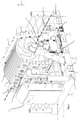
- Fig. 1 shows a layout of the present meat grill installation 100.
- the meat grill installation has a detachable horizontal cylindrical element 10.
- This cylindrical element is more particularly a cylindrical carrier for meat 22.
- the cylindrical element 10 is connected to a frame 21 of the installation 100 in such a manner that it can rotate around its main axis A.
- the element 10 may, in order to become reversibly disconnected from the installation as shown in Fig. 1 , be lifted out of connection in an upward direction D with respect to the frame 21.
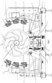
- Fig. 2 shows a cross-sectional view of the installation 100 according to Fig. 1 .
- the cylindrical element 10 comprises a series of meat fixators 12 at its boundary 24. That is to say that the cylindrical element 10 has, distributed along its circumference, a series of fixators 12, such as skewers or spikes onto which meat 22 can be removably fixed to the cylindrical element. Skewer and spike are here used as interchangeable terms.
- the skewers extend in the axial direction of the cylindrical element 10.
- the boundary 24 can be understood to mean the cylindrical surface of the cylindrical element 10 on which meat is carried, such as via the skewers.
- This cylindrical surface is provided with recesses 14 extending axially along the circumference such that fixators 12, such as the skewers, can be received therein.
- the cylindrical element 10 has in this example in each recess 14 a plurality of uptake elements 13.
- These uptake elements 13 are holders or clamps for removably fixing the fixators 12 within a respective recess.
- the uptake elements are holed partitions which extend in a radially outward direction from the base of a respective recess to an upper edge of said respective recess. The diameter of the hole (not shown, but customary) of such a partition is greater or equal to the diameter of the skewers.
- Figure 7b shows the condition of the cylindrical element prior to the casting of meat onto the element 10.
- Figure 7a the skewers are shown for the purpose of showing their final position after insertion.
- Fig. 4 also shows condition of the cylindrical element 10 after the meat 22 has been fixed thereto.
- Fig. 5 shows that an adaptable diaphragm 11 is provided at each distal end of the cylindrical element.
- Each diaphragm comprises a plurality of partially overlapping flaps 26 which at least partially cover the meat at the distal ends of the cylindrical element 10.
- Each diaphragm is arranged to at least partly open and close by the overlapping of the flaps.
- the diaphragm 11 is at least partially open when the flaps assume a position in which the flaps extend radially outward with respect to the cylindrical element 10 such that there exists an opening between flaps.
- the diaphragm 11 is closed when the flaps are retracted radially inwards such that there is no opening between flaps.
- Fig. 5 shows a position wherein the diaphragm is closed.
- each flap 26 of a particular diaphragm 11 is able to rotate around a connection point 27 by which it is fixed to the cylindrical element for radially extending or retracting thereby.
- the flaps 26 of each diaphragm 11 may be connected to move jointly in order to assume a partly open or closed position.
- the installation 100 can further be seen to have a motor 20 for rotating the cylindrical element 10.
- This motor can be an electromotor.
- the main axis is also referred to as the horizontal axis. However, it shall be understood that in practice this axis may be tilted with respect to a gravitational horizontal, such as between 0 - 10 degrees.
- the installation can also be seen to comprise at least two, in this case six, heaters 30 for grilling the meat.
- the installation may optionally have a conveyor belt 60, which is in this example arranged directly underneath the cylindrical element 10.
- the conveyor belt 60 and is in this example used for receiving and transporting cooked meat that has been cut off from the cylindrical element 10 by a cutting element 70.
- the conveyor belt moves, in use, in a direction parallel to the longitudinal axis of the cylindrical element 10.
- the six heaters are optionally distributed in two groups as shown in Fig.2 . Each group is provided to heat opposite sides of the cylindrical element 10 such as to allow space between heating elements for the conveyor belt.
- the heaters are in this example gas heaters and as such a gas supply 31 for feeding gas to the heaters is provided to the installation.
- IR-radiation heaters may, such as electrical heaters, may be used.
- the (gas) heaters 30 provide heat at an intensity of 100-200 W/m 2 , and operate at a temperature of 700-1000 °C.
- the heaters are merely arranged to emit infrared radiation at 100-200 W/m 2 at a wavelength of 1-5 ⁇ m and do not require to operate at any specific temperature.
- the meat 22 is heated at a rate of 1000 kg/4-12 h.
- the heaters heat the outer surface of the meat 22 as the meat is rotated with the cylindrical element 10.
- the heaters can be seen to be placed at equal distance from the main axis A.
- the heaters are rotated, that is to say tilted, such that the direction of heating of each heater is directed towards and is substantially perpendicular to the axis A.
- An Additional motor (not shown, but customary) may also be comprised in the installation for tilting the heaters.
- each heater 30 is arranged for being manually tilted.
- a length of each heater 30 is individually adapted to a length of the cylindrical element, typically being more or less ( ⁇ 5%) the same length. That is to say that the total length of the heater is equal to 0,95 - 1,05 times the length of the cylindrical element 10.
- the installation 100 comprises a position adapter 40.
- Each heater is connected to the frame 21 of the installation 100 via such an adapter 40.
- the distance of each heater 30 to the cylindrical element 10 may be adjusted manually.
- the adapter 40 is in this example, but entirely optionally arranged for slidably connecting the heater 30 to the frame 21 and for maintaining the heater at a predetermined distance from the cylindrical element, that is to say to the meat on the cylindrical element 10.
- At least one sensor 50 is provided, preferably at least two sensors, for determining a temperature of the heated meat.
- This at least one sensor 50 is in this example an infrared temperature sensor. The sensed temperature is in this example used to increase or decrease the distance of the heaters with respect to the meat.
- the distance of the heaters is adjusted such that the temperature remains equal throughout the cooking process.
- the at least one sensor 50 is used to increase or decrease the temperature of the heaters themselves, to increase or decrease a rotation velocity of the cylindrical element, or maintain these variables, or a combination thereof.
- the conveyer belt 60 is provided located underneath the cylindrical element for receiving and transporting heated meat that is cut off from .
- the conveyor belt typically moves in operation in a direction parallel to the longitudinal axis of the cylindrical element.
- a cutting element 70 in this example a knife, is provided for removing a slice of a predetermined thickness of meat from the detachable cylindrical element, which typically moves in operation in the same or opposite direction as the conveyor belt.
- Fig. 6 shows the cutting element 60 to be a rotating disc provided with a sharp edge.
- the cutting element 60 is provided on a shuttle 65.
- Said shuttle is arranged for moving within a shuttle track 68.
- the shuttle 65 is adapted for forward movement and backward movement along a shuttle track 68.
- the shuttle track extends in a direction parallel to the axis A.
- a tilt of the cutting element can be adjusted via a tilt actuator 67, such as a tilt handle, comprised in the shuttle 65.
- a tilt activator 66 such as a notch, is provided along the shuttle track 68.
- the tilt actuator 67 is actuated by the activator 66 when, is use, the shuttle reaches the activator 66 as it is moved along the track.
- the activator 66 is arranged such that the shuttle tilts and fixes the cutting element in a forward angle of 5-35 degrees with respect to the horizontal plane, and wherein during backward movement the shuttle tilts and fixes the cutting element in a backward angle of minus 5-35 degrees with respect to the horizontal plane.
- the shuttle track 68 and conveyor 60 are jointly supported on at least three adaptable supports 80. These supports 80 can be raised or lowered such as to jointly move the cutting element 60 in a direction towards or away from the cylindrical element respectively.
- the supports 80 are mutually connected by a connector 81, in this example a chain.
- the supports 80 further comprise a worm gear 82, and a gear 83 adapted to be driven by the connector.
- the manner in which the shuttle moves along the track is also motorized.
- the shuttle may be operated such as to move across the full or a partial length of the track 68 and at adjustable speed. This determines the length of slices.
- At least one controller such as a computer (not shown, but customary), is provided for driving the motor, for maintaining and/or adapting a temperature of each individual heater, for driving the at least two position adapters, for receiving the sensor output, for providing feedback to at least one heater, and for controlling the length of slices of meat, for controlling the thickness of slices of meat, and combinations thereof.
- a computer not shown, but customary
- the at least one controller is optionally arranged for controlling all motorized operations described herein above, including regulating heater temperature by regulating for example the gas flow to the heaters. Further optionally the controller is provided with a human interface (not shown, but customary), to allow an operator to control at least some of the motorized operations and/or heater temperature via said human interface.
- the human interface may comprise start and stop buttons (not shown, but customary) as well as buttons for regulating the above mentioned motorized operations and gas flow.
- software may be provided for controlling the installation, typically loaded on a storage medium and provided as a processor or to a processor.
- the storage medium may be part of the processor memory of the processor or a non-transitory computer readable medium, such as a hard drive or solid state drive. Therewith large quantities of meat can be processed in a well-controlled manner in a relatively short time.
- the cooking and cutting process can be controlled by the controller such that slices of meat have a length of 1-150 cm, a thickness of 1-5 mm, and a width of 10-100 mm.
- the meat is heated to a temperature of 100-170 °C.
- the cylindrical element 10 rotates with a speed of 1-10 degrees/sec and the conveyor belt runs with a speed of 0.5-2 m/sec.
- the meat 22 is selected from chicken, pork, lamb, beef, fish, plant protein, microbial protein, cell protein, insect protein, in vitro meat, or a combinations thereof.
- a water supply 55 is present for adjusting the water content of the meat. This prevents the meat from drying out during the cooking process.
- a steam supply 56 is also present for adjusting the temperature of the meat as it is cooked.
- the water and/or steam supply is controlled by means of the controller.
- the frame comprises a support base 27 for keeping the installation elevated off of the floor. Further security measures may also be present, such as a fencing 28.
- Figs. 7a and b show the present cylindrical element without and with meat. Further a releasable confinement 17 and a closure 18 is also shown in these figures, in a partly opened situation.
- cutter and cutting element will be understood to be interchangeable.
- cylindrical element and cylindrical carrier will also be understood to be interchangeable.
Description
- The present invention is in the field of a meat grill installation for preparing large quantities of meat, and a method of preparing such large quantities of meat. Typically meat may be prepared by heating in an oven, in a stove or in a pan, to a temperature sufficient to cook the meat. Meat may be fully cooked or partly cooked.
- Meat comprises water, protein, and fat. It may be eaten raw, but normally it is cooked and often seasoned as well. Unprocessed meat may have health risks due to infection with and decomposition by bacteria and fungi. It is therefore best cooled, or frozen, and thereafter processed quickly.
- For various food items, such as pizza's, meat is used in thin slices. Preparation of large quantities of these thin slices is typically required, but still has to be done at least partly by hand. The capacity, per hour, is therefore typically limited.
- The present invention therefore relates to a meat grill installation and a method for heating frozen meat, which solves one or more of the above problems and drawbacks of the prior art, providing reliable results, without jeopardizing functionality and advantages.
- A meat grill installation of the state of the art is known from
DE-C-19545699 - The present invention relates to a meat grill installation comprising a detachable horizontal cylindrical carrier, hereinafter referred to as a cylindrical element for carrying meat, typically a large quantity of meat. The cylindrical element comprises a series of meat fixators at its boundary. It further comprises a motor for rotating the cylindrical element around its horizontal axis. The horizontal axis may be slightly tilted. Further motors may be present, or combined, such as for driving a conveyor belt, for driving adaptable supports, for rotating a cutter, hereinafter named a cutting element, for driving position adapters, etc. It further comprises at least two
heaters 30 for grilling the meat, typically 2-5 heaters at either side of the cylindrical element, such as 3-4 heaters, wherein the at least two heaters are divided over a circumference of the cylindrical element, typically not evenly divided in view of other parts being present, such as a conveyor belt. Heaters are typically provided at a substantially equal distance from the centre of the cylindrical element and are typically rotated, that is to say tilted, such that a heating part thereof faces the to be heated meat as much as possible. A length of each heater is individually adapted to a length of the cylindrical element, typically being more or less (±5%) the same length. Therewith the heaters are adapted to heat the meat evenly and as thorough as required. It further comprises at least two position adapters for maintaining each individual heater at a predetermined distance from the cylindrical element. Therewith the speed of heating is controlled. When meat is cut away the radius of the cylindrical element comprising meat becomes smaller and smaller, causing the heaters to be further and further away from the meat. Therefore, position adapters are provided to maintain the heaters at a substantially similar distance from the meat over time. Further at least one sensor is provided, preferably at least two sensors, for determining a temperature of the heated meat. The sensed temperature can be used to increase or decrease the distance of the heaters with respect to the meat, to increase or decrease the temperature of the heaters, to increase or decrease a rotation velocity of the cylindrical element, or maintain these variables, or a combination thereof. Further a conveyer belt is provided located underneath the cylindrical element for receiving and transporting heated meat. The conveyor belt typically moves in operation in a direction parallel to the longitudinal axis of the cylindrical element. For cutting meat a cutting element is provided for removing a slice of a predetermined thickness of meat from the detachable cylindrical element, which typically moves in operation in the same or opposite direction as the conveyor belt. The thickness may be varied by tilting the cutting element and/or adjusting the vertical position thereof. The width may be varied by providing a wider or smaller cutting element, and the length may be varied by increasing or decreasing a speed of the cutting element and a length of a path travelled by the cutting element, or a combination thereof. Also at least one controller is provided for driving the motor, for maintaining and/or adapting a temperature of each individual heater, for driving the at least two position adapters, for receiving the sensor output, for providing feedback to at least one heater, and for controlling thickness of slices of meat, and combinations thereof. The installation may be provided on a frame, and further security measures may be present, such as a fencing. For operation controls are typically provided, such as start and stop buttons. In addition, software may be provided for controlling the installation, typically loaded on a storage medium and provided as a processor. Therewith large quantities of meat can be processed in a well-controlled manner in a relatively short time. - In a second aspect the present invention relates to a method of heating 100-3000 kg of frozen meat, comprising providing a cylindrical element provided with meat, and the at least one diaphragm opened, moving the cylindrical element into the meat grill installation of the present invention, heating the meat, and cutting at least one slice of meat.
- Thereby the present invention provides a solution to one or more of the above-mentioned problems and drawbacks.
- Advantages of the present description are detailed throughout the description.
- The present invention relates in a first aspect to an installation according to claim 1.
- In an exemplary embodiment the present meat grill installation may further comprise at least three in height adaptable supports, wherein the height of the supports is controlled by the at least one controller, and wherein the conveyor belt, at least one sensor, and cutting element are attached to the at least three supports.
- In an exemplary embodiment the present meat grill installation may further comprise at least one water supply, preferably at least one water supply at each side, for adapting a water content of the meat, and/or comprising at least one
steam supply 56, preferably at least one steam supply at each side, for adapting a temperature of the meat. These supplies are typically directed towards the to be processed meat, i.e. in a direction parallel to a radius of the cylindrical element - In an exemplary embodiment of the present meat grill installation the cylindrical element may comprise two diaphragms, one at either side thereof, for enclosing meat, which diaphragms are adapted to at least partly open and close. Such as under the influence of escaping gasses, such as steam, during the heating of the meat.
- In an exemplary embodiment of the present meat grill installation the cylindrical element may be adapted to be maintained at a fixed height.
- In an exemplary embodiment of the present meat grill installation the supports may be mutually connected by a connector, such as a chain.
- In an exemplary embodiment of the present meat grill installation the at least one controller may drive the connector and thereby the height of the supports.
- In an exemplary embodiment of the present meat grill installation the supports may comprise a worm gear, and a gear adapted to be driven by the connector.
- In an exemplary embodiment of the present meat grill installation the conveyor belt may be an endless conveyor belt.
- In an exemplary embodiment of the present meat grill installation the horizontal speed of the cutting element and conveyor belt may be adapted to one and another.
- In an exemplary embodiment of the present meat grill installation the cutting element may be adapted to be driven back and forth.
- In an exemplary embodiment the present meat grill installation may further comprise a shuttle in connection with the cutting element, wherein the shuttle is adapted for forward movement and backward movement, wherein during forward movement the shuttle tilts and fixes the cutting element in a forward angle of 5-35 degrees, such as 10-30 degrees, e.g. 20-25 degrees, with respect to the horizontal plane, and wherein during backward movement the shuttle tilts and fixes the cutting element in a backward angle of minus 5-35 degrees, such as 10-30 degrees, e.g. 20-25 degrees, with respect to the horizontal plane, wherein tilting is preferably provided by at least one
tilt activator 66, such as a notch. - In an exemplary embodiment of the present meat grill installation the cutting element may be a rotating disc provided with a sharp edge. The rotating disc may have a diameter of 10-300 mm, such as 20-150 mm, and may rotate with a speed of 100-6000 rpm, preferably 200-1000 rpm, such as 300-600 rpm.
- In an exemplary embodiment the present meat grill installation may further comprise a hydrocarbon gas supply, and wherein the at least one heater is a gas heater, such as ceramic gas heater. The hydrocarbon gas may be methane.
- In an exemplary embodiment of the present meat grill installation the sensor may be an Infrared sensor.
- In an exemplary embodiment of the present meat grill installation the cylindrical element may comprise an alarm, such as an audio and/or visual alarm. Optionally, in combination with an infrared sensor the alarm is triggered when, is use, a meat temperature is detected below a minimum desired cooking temperature and/or when, in use, a meat temperature is detected above a maximum desired cooking temperature.
- In an exemplary embodiment of the present meat grill installation the series of meat fixators may comprise 2-30 spikes, such as 5-20 spikes.
- In an exemplary embodiment of the present meat grill installation the cylindrical element may comprise at least two
uptake elements 13 per meat fixator, such as 3-6 uptake elements, such as trapezium shaped uptake elements provided with an opening therein. As such the uptake elements, and spikes are well fixed and can carry the weight of the meat. - In an exemplary embodiment of the present meat grill installation the cylindrical element may comprise at least four
recesses 14 provided along a longitudinal axis of the cylindrical element, such as 2-30 recesses, preferably wherein recesses have a trapezium shaped cross-section. The trapezium shape is found to improve fixation of uptake elements and spikes. - In an exemplary embodiment of the present method the slice of meat may have a length of 1-150 cm, preferably 20-100 cm, such as 30-80 cm, a thickness of 1-5 mm, such as 2-4 mm, and a width of 10-100 mm, such as 20-50 mm.
- In an exemplary embodiment of the present method the meat may be heated to a temperature of 100-170 °C, such as 120-150 °C. Said temperature refers to an outer layer of the meat (of a thickness to be cut typically) and may be measured with the present sensor. Too high temperatures are found to burn the meat and/or to dry the meat too much, whereas too low temperatures result in not fully prepared meat. The temperature and the rotating speed of the present cylindrical element may be adjusted and adapted to one and another, such as by the present controller and/or feedback loop.
- In an exemplary embodiment of the present method the heaters may provide infrared radiation at a wavelength of 1-5 µm, preferably 2-4 µm. This radiation is found particularly suited, and may be provided by the ceramic elements in the heaters.
- In an exemplary embodiment of the present method the heaters may provide infrared radiation at an intensity of 100-1000 W/m2, preferably 200-800 W/m2, more preferably 300-600 W/m2, such as preferably 400-500 W/m2.
- In an exemplary embodiment of the present method the heaters may operate at a temperature of 700-1000 °C, preferably 800-900 °C.
- In an exemplary embodiment the infrared gas burner wave length is 2-4 microns. The gas fired infrared radiant burners may be unidirectional. A temperature of 900°C can be achieved, and radiant energy is emitted. This wave band is found to be ideal for application to cooking equipment because it provides suitable radiation penetration into protein comprising meat to convert the radiated energy to heat. With infrared radiation, penetration of the electromagnetic radiation below the surface of the meat to be cooked is found to be limited to the outer 2mm. As such an intense skin heating is provided. It is found that heat generated and absorbed at the surface of the meat is small, as a result of placing the meat at a distance from the heat source. Slight heat increases at the meat's surface will help to shorten the cooking time. The surface of the meat is best heated not too much as than only a slow rate of moisture content loss is observed. The rate of flavor and color development will also be slow. Evaporation of water may be compensated for, by providing water and/or steam.
- In an exemplary embodiment of the present method the cylindrical element may rotate with a speed of 1-10 degrees/sec, preferably 1-3 degrees/sec. At this rate good cooking properties and sufficient yield are obtained.
- In an exemplary embodiment of the present method the conveyor belt may run with a speed of 0.5-2 m/sec, such as 1-1.5 m/sec.
- In an exemplary embodiment of the present method the meat may be heated at a rate of 1000 kg/4-12 h, such as 500 kg/4-12 h.
- In an exemplary embodiment of the present method the meat may be selected from chicken, pork, lamb, beef, fish, plant protein, microbial protein, cell protein, insect protein, and combinations thereof. It is noted that strictly speaking plant protein and some of the further sources of protein mentioned are not meat, but the installation works equally well for those other forms of protein, mutatis mutandis.
- In an exemplary embodiment of the present method the meat may be cooked, grilled, or a combination thereof.
- The one or more of the above examples and embodiments may be combined, falling within the scope of the invention.
- The below relates to examples, which are not limiting in nature.
- The invention is further detailed by the accompanying figures, which are exemplary and explanatory of nature and are not limiting the scope of the invention. To the person skilled in the art it may be clear that many variants, being obvious or not, may be conceivable falling within the scope of protection, defined by the present claims.
- The invention although described in detailed explanatory context may be best understood in conjunction with the accompanying figures.
-
Fig. 1 shows a layout of the present meat grill installation. -
Fig. 2 shows a cross-sectional side view of the present installation. -
Fig. 3 shows a view of the present cylindrical element. -
Figs 4 shows a view of the present cylindrical element including meat. -
Fig. 5 shows a view of the present cylindrical element including meat and functioning of the diaphragm. -
Fig. 6 shows a side view of the conveyor belt, shuttle and cutting element. -
Fig. 7a shows the present cylindrical element without meat. -
Fig. 7b shows shows the present cylindrical element with - In the figures:
- 100
- present installation
- 10
- cylindrical element
- 11
- adaptable diaphragm
- 12
- fixator
- 13
- uptake element
- 14
- recess
- 15
- cylindrical element gear
- 16
- air and pressure relief holes
- 17
- releasable confinement
- 18
- releasable closure
- 20
- motor
- 21
- frame22 meat
- 24
- boundary
- 26
- flap
- 27
- support base
- 28
- fence
- 30
- heater
- 31
- gas supply
- 40
- position adapter
- 50
- sensor
- 55
- water supply
- 56
- steam supply
- 60
- conveyor belt
- 65
- shuttle
- 66
- tilt activator
- 67
- tilt actuator
- 68
- shuttle track
- 70
- cutting element
- 80
- adaptable support
- 81
- connector
- 82
- worm gear
- 83
- gear
-
Fig. 1 shows a layout of the presentmeat grill installation 100. The meat grill installation has a detachable horizontalcylindrical element 10. This cylindrical element is more particularly a cylindrical carrier formeat 22. Thecylindrical element 10 is connected to aframe 21 of theinstallation 100 in such a manner that it can rotate around its main axis A. Theelement 10 may, in order to become reversibly disconnected from the installation as shown inFig. 1 , be lifted out of connection in an upward direction D with respect to theframe 21.Fig. 2 shows a cross-sectional view of theinstallation 100 according toFig. 1 . - In
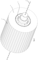
Fig. 3 it is shown that thecylindrical element 10 comprises a series ofmeat fixators 12 at itsboundary 24. That is to say that thecylindrical element 10 has, distributed along its circumference, a series offixators 12, such as skewers or spikes onto whichmeat 22 can be removably fixed to the cylindrical element. Skewer and spike are here used as interchangeable terms. The skewers extend in the axial direction of thecylindrical element 10. Theboundary 24 can be understood to mean the cylindrical surface of thecylindrical element 10 on which meat is carried, such as via the skewers. This cylindrical surface is provided withrecesses 14 extending axially along the circumference such thatfixators 12, such as the skewers, can be received therein. Thecylindrical element 10 has in this example in each recess 14 a plurality ofuptake elements 13. Theseuptake elements 13 are holders or clamps for removably fixing thefixators 12 within a respective recess. InFig. 3 the uptake elements are holed partitions which extend in a radially outward direction from the base of a respective recess to an upper edge of said respective recess. The diameter of the hole (not shown, but customary) of such a partition is greater or equal to the diameter of the skewers. - Once the
meat 22 is cast around thecylindrical element 10, as shown inFigure 7b . The skewers are inserted such as to skewer the meat and fix it to theelement 10.Figure 7a shows the condition of the cylindrical element prior to the casting of meat onto theelement 10. InFigure 7a the skewers are shown for the purpose of showing their final position after insertion. -
Fig. 4 also shows condition of thecylindrical element 10 after themeat 22 has been fixed thereto. -
Fig. 5 shows that anadaptable diaphragm 11 is provided at each distal end of the cylindrical element. Each diaphragm comprises a plurality of partially overlappingflaps 26 which at least partially cover the meat at the distal ends of thecylindrical element 10. Each diaphragm is arranged to at least partly open and close by the overlapping of the flaps. Thediaphragm 11 is at least partially open when the flaps assume a position in which the flaps extend radially outward with respect to thecylindrical element 10 such that there exists an opening between flaps. Thediaphragm 11 is closed when the flaps are retracted radially inwards such that there is no opening between flaps.Fig. 5 shows a position wherein the diaphragm is closed. It is noted that eachflap 26 of aparticular diaphragm 11 is able to rotate around aconnection point 27 by which it is fixed to the cylindrical element for radially extending or retracting thereby. Theflaps 26 of eachdiaphragm 11 may be connected to move jointly in order to assume a partly open or closed position. - In
Fig. 1 theinstallation 100 can further be seen to have amotor 20 for rotating thecylindrical element 10. This motor can be an electromotor. However, other motors-types are possible. The main axis is also referred to as the horizontal axis. However, it shall be understood that in practice this axis may be tilted with respect to a gravitational horizontal, such as between 0 - 10 degrees. The installation can also be seen to comprise at least two, in this case six,heaters 30 for grilling the meat. The installation may optionally have aconveyor belt 60, which is in this example arranged directly underneath thecylindrical element 10. Theconveyor belt 60 and is in this example used for receiving and transporting cooked meat that has been cut off from thecylindrical element 10 by a cuttingelement 70. The conveyor belt moves, in use, in a direction parallel to the longitudinal axis of thecylindrical element 10. The six heaters are optionally distributed in two groups as shown inFig.2 . Each group is provided to heat opposite sides of thecylindrical element 10 such as to allow space between heating elements for the conveyor belt. The heaters are in this example gas heaters and as such agas supply 31 for feeding gas to the heaters is provided to the installation. Alternatively, IR-radiation heaters may, such as electrical heaters, may be used. The (gas)heaters 30 provide heat at an intensity of 100-200 W/m2, and operate at a temperature of 700-1000 °C. Should the heaters instead be electric they are merely arranged to emit infrared radiation at 100-200 W/m2 at a wavelength of 1-5 µm and do not require to operate at any specific temperature. In one example themeat 22 is heated at a rate of 1000 kg/4-12 h. The heaters heat the outer surface of themeat 22 as the meat is rotated with thecylindrical element 10. The heaters can be seen to be placed at equal distance from the main axis A. The heaters are rotated, that is to say tilted, such that the direction of heating of each heater is directed towards and is substantially perpendicular to the axis A. An Additional motor (not shown, but customary) may also be comprised in the installation for tilting the heaters. In this example theheaters 30 are arranged for being manually tilted. A length of eachheater 30 is individually adapted to a length of the cylindrical element, typically being more or less (±5%) the same length. That is to say that the total length of the heater is equal to 0,95 - 1,05 times the length of thecylindrical element 10. For eachheater 30 theinstallation 100 comprises aposition adapter 40. Each heater is connected to theframe 21 of theinstallation 100 via such anadapter 40. The distance of eachheater 30 to thecylindrical element 10 may be adjusted manually. Theadapter 40 is in this example, but entirely optionally arranged for slidably connecting theheater 30 to theframe 21 and for maintaining the heater at a predetermined distance from the cylindrical element, that is to say to the meat on thecylindrical element 10. When, in use, meat is cut away the radius of the total radius of the cylindrical element with meat becomes smaller and smaller, causing the heaters to be further and further away from the outer surface of themeat 22. Therefore, position adapters are provided to maintain the heaters at a substantially similar distance from the meat over time. Theseadapters 40 may be motorised such as to allow the heaters to be slid towards thecylindrical element 10. This change in distance will result in a change in overall change in surface temperature of the meat, which is detectable. To this end at least onesensor 50 is provided, preferably at least two sensors, for determining a temperature of the heated meat. This at least onesensor 50 is in this example an infrared temperature sensor. The sensed temperature is in this example used to increase or decrease the distance of the heaters with respect to the meat. The distance of the heaters is adjusted such that the temperature remains equal throughout the cooking process. Optionally or alternatively, the at least onesensor 50 is used to increase or decrease the temperature of the heaters themselves, to increase or decrease a rotation velocity of the cylindrical element, or maintain these variables, or a combination thereof. - The
conveyer belt 60 is provided located underneath the cylindrical element for receiving and transporting heated meat that is cut off from . The conveyor belt typically moves in operation in a direction parallel to the longitudinal axis of the cylindrical element. For cutting meat a cuttingelement 70, in this example a knife, is provided for removing a slice of a predetermined thickness of meat from the detachable cylindrical element, which typically moves in operation in the same or opposite direction as the conveyor belt. -
Fig. 6 shows the cuttingelement 60 to be a rotating disc provided with a sharp edge. The cuttingelement 60 is provided on ashuttle 65. Said shuttle is arranged for moving within ashuttle track 68. Theshuttle 65 is adapted for forward movement and backward movement along ashuttle track 68. The shuttle track extends in a direction parallel to the axis A. A tilt of the cutting element can be adjusted via atilt actuator 67, such as a tilt handle, comprised in theshuttle 65. Atilt activator 66, such as a notch, is provided along theshuttle track 68. In this example thetilt actuator 67 is actuated by theactivator 66 when, is use, the shuttle reaches theactivator 66 as it is moved along the track. Theactivator 66 is arranged such that the shuttle tilts and fixes the cutting element in a forward angle of 5-35 degrees with respect to the horizontal plane, and wherein during backward movement the shuttle tilts and fixes the cutting element in a backward angle of minus 5-35 degrees with respect to the horizontal plane. In this example, theshuttle track 68 andconveyor 60 are jointly supported on at least threeadaptable supports 80. These supports 80 can be raised or lowered such as to jointly move the cuttingelement 60 in a direction towards or away from the cylindrical element respectively. The supports 80 are mutually connected by aconnector 81, in this example a chain. By moving the cutting element in the above described manner the thickness of meat slices can be adjusted and maintained. The supports 80 further comprise aworm gear 82, and agear 83 adapted to be driven by the connector. The manner in which the shuttle moves along the track is also motorized. The shuttle may be operated such as to move across the full or a partial length of thetrack 68 and at adjustable speed. This determines the length of slices. - At least one controller, such as a computer (not shown, but customary), is provided for driving the motor, for maintaining and/or adapting a temperature of each individual heater, for driving the at least two position adapters, for receiving the sensor output, for providing feedback to at least one heater, and for controlling the length of slices of meat, for controlling the thickness of slices of meat, and combinations thereof.
- The at least one controller is optionally arranged for controlling all motorized operations described herein above, including regulating heater temperature by regulating for example the gas flow to the heaters. Further optionally the controller is provided with a human interface (not shown, but customary), to allow an operator to control at least some of the motorized operations and/or heater temperature via said human interface. For operation the human interface may comprise start and stop buttons (not shown, but customary) as well as buttons for regulating the above mentioned motorized operations and gas flow. In addition, software may be provided for controlling the installation, typically loaded on a storage medium and provided as a processor or to a processor. The storage medium may be part of the processor memory of the processor or a non-transitory computer readable medium, such as a hard drive or solid state drive. Therewith large quantities of meat can be processed in a well-controlled manner in a relatively short time.
- In this example the cooking and cutting process can be controlled by the controller such that slices of meat have a length of 1-150 cm, a thickness of 1-5 mm, and a width of 10-100 mm. The meat is heated to a temperature of 100-170 °C. In use, the
cylindrical element 10 rotates with a speed of 1-10 degrees/sec and the conveyor belt runs with a speed of 0.5-2 m/sec. - It shall be understood that a variety of different meats or compositions of meats may be cooked using the described
installation 100. As a matter of example themeat 22 is selected from chicken, pork, lamb, beef, fish, plant protein, microbial protein, cell protein, insect protein, in vitro meat, or a combinations thereof. - In
Fig. 2 awater supply 55 is present for adjusting the water content of the meat. This prevents the meat from drying out during the cooking process. Asteam supply 56 is also present for adjusting the temperature of the meat as it is cooked. Optionally, the water and/or steam supply is controlled by means of the controller. - In the example of
Fig. 1 the frame comprises asupport base 27 for keeping the installation elevated off of the floor. Further security measures may also be present, such as a fencing 28.Figs. 7a andb show the present cylindrical element without and with meat. Further areleasable confinement 17 and aclosure 18 is also shown in these figures, in a partly opened situation. - The figures have also been detailed throughout the description. The terms cutter and cutting element will be understood to be interchangeable. The terms cylindrical element and cylindrical carrier will also be understood to be interchangeable.
Claims (15)
- Meat grill installation (100) comprisinga detachable horizontal cylindrical element (10) for carrying meat, the cylindrical element comprising a series of meat fixators (12),a motor (20) for rotating the cylindrical element around its horizontal axis,at least two heaters (30) for grilling the meat, the at least two heaters divided over a circumference of the cylindrical element, and wherein a length of each heater is individually adapted to a length of the cylindrical element,at least two position adapters (40) for maintaining each individual heater at a predetermined distance from the cylindrical element,at least one sensor (50), preferably at least two sensors, for determining a temperature of the heated meat,a conveyer belt (60) located underneath the cylindrical element for receiving and transporting heated meat,a cutting element (70) for removing a slice of a predetermined thickness of meat from the detachable cylindrical element, andat least one controller for driving the motor, for maintaining and/or adapting a temperature of each individual heater, for driving the at least two position adapters, for receiving the sensor output, for providing feedback to at least one heater, and for controlling thickness of slices of meat.
- Meat grill installation according to embodiment 1, further comprising at least three in height adaptable supports (80), wherein the height of the supports is controlled by the at least one controller, and wherein the conveyor belt, at least one sensor, and cutting element are attached to the at least three supports.
- Meat grill installation according to claim 1 or 2, further comprising at least one water supply (55), preferably at least one water supply at each side, for adapting a water content of the meat, and/or comprising at least one steam supply (56), preferably at least one steam supply at each side, for adapting a temperature of the meat.
- Meat grill installation according to any of claims 1-3, wherein the cylindrical element comprises two diaphragms (11), one at either side thereof, for enclosing meat, which diaphragms are adapted to at least partly open and close.
- Meat grill installation according to any of claims 2-4, wherein the supports are mutually connected by a connector (81), such as a chain, and wherein the at least one controller drives the connector and thereby the height of the supports.
- Meat grill installation according to any of claims 2-5, wherein the supports comprise a worm gear (82), and a gear (83) adapted to be driven by the connector.
- Meat grill installation according to any of claims 1-6, wherein the horizontal speed of the cutting element and conveyor belt are adapted to one and another.
- Meat grill installation according to any of claims 1-7, wherein the cutting element is adapted to be driven back and forth.
- Meat grill installation according to any of claims 1-8, further comprising a shuttle (65) in connection with the cutting element, wherein the shuttle is adapted for forward movement and backward movement, wherein during forward movement the shuttle tilts and fixes the cutting element in a forward angle of 5-35 degrees with respect to the horizontal plane, and wherein during backward movement the shuttle tilts and fixes the cutting element in a backward angle of minus 5-35 degrees with respect to the horizontal plane, wherein tilting is preferably provided by at least one tilt activator (66), such as a notch.
- Meat grill installation according to any of claims 1-9, wherein the series of meat fixators comprise 2-30 spikes, such as 5-20 spikesand/orwherein the cylindrical element comprises at least two uptake elements (13) per meat fixator (12), such as 3-6 uptake elements, such as trapezium shaped uptake elements provided with an opening thereinand/orwherein the cylindrical element comprising at least four recesses (14) provided along a longitudinal axis of the cylindrical element, such as 2-30 recesses, preferably wherein recesses have a trapezium shaped cross-section.
- Method of heating 100-3000 kg of frozen meat, comprisingproviding a cylindrical element (10) provided with meat, and the at least one diaphragm opened,moving the cylindrical element into the meat grill installation of any of claims 1-10,heating the meat, andcutting at least one slice of meat.
- Method according to claim 11, wherein the slice of meat has a length of 1-150 cm, a thickness of 1-5 mm, and a width of 10-100 mm.
- Method according to claim 11 or 12, wherein the meat is heated to a temperature of 100-170 °C.
- Method according to any of claims 11-13, wherein the heaters provide infrared radiation at a wavelength of 1-5 µm, and/or at an intensity of 100-200 W/m2, and/or operate at a temperature of 700-1000 °C.
- Method according to any of claims 11-14, wherein the meat is cooked, grilled, or a combination thereof.
Priority Applications (1)
| Application Number | Priority Date | Filing Date | Title |
|---|---|---|---|
| PL20182006T PL3760087T3 (en) | 2019-06-26 | 2020-06-24 | Meat grill installation |
Applications Claiming Priority (1)
| Application Number | Priority Date | Filing Date | Title |
|---|---|---|---|
| NL2023386A NL2023386B1 (en) | 2019-06-26 | 2019-06-26 | Meat grill installation |
Publications (2)
| Publication Number | Publication Date |
|---|---|
| EP3760087A1 EP3760087A1 (en) | 2021-01-06 |
| EP3760087B1 true EP3760087B1 (en) | 2022-03-02 |
Family
ID=68000021
Family Applications (1)
| Application Number | Title | Priority Date | Filing Date |
|---|---|---|---|
| EP20182006.5A Active EP3760087B1 (en) | 2019-06-26 | 2020-06-24 | Meat grill installation |
Country Status (7)
| Country | Link |
|---|---|
| US (1) | US11684209B2 (en) |
| EP (1) | EP3760087B1 (en) |
| DK (1) | DK3760087T3 (en) |
| ES (1) | ES2914862T3 (en) |
| NL (1) | NL2023386B1 (en) |
| PL (1) | PL3760087T3 (en) |
| PT (1) | PT3760087T (en) |
Citations (1)
| Publication number | Priority date | Publication date | Assignee | Title |
|---|---|---|---|---|
| EP2412283B1 (en) * | 2010-07-30 | 2014-08-13 | Mustafa Pusat | A meat slicing apparatus, a method of using it and a preparation unit for use with the meat slicing apparatus |
Family Cites Families (10)
| Publication number | Priority date | Publication date | Assignee | Title |
|---|---|---|---|---|
| US4050370A (en) * | 1976-03-11 | 1977-09-27 | Schmidt, Trustee Under Harry J. Hoenselaar Trust Agreement Of Oct. 4, 1973, Mary Jane | Spiral meat slicer with improved reciprocating knife structure |
| DE19545699C1 (en) | 1995-12-07 | 1997-05-22 | Tevfik Guel | Grill with a rotatable meat skewer |
| IES20030130A2 (en) * | 2003-02-24 | 2004-09-08 | Higgins Stevens | Food processing |
| WO2017062524A1 (en) * | 2015-10-05 | 2017-04-13 | Nieco Corporation | Automated broiler with product temperature feedback system |
| NL2019287B1 (en) * | 2017-07-20 | 2019-02-01 | Cjet B V | Automatic meat cutting apparatus |
| WO2019040588A1 (en) * | 2017-08-25 | 2019-02-28 | Taylor Commercial Foodservice Inc. | Grill conveyor staging system |
| US20190191926A1 (en) * | 2017-12-21 | 2019-06-27 | Buckaroo Taco & Grill, LLC | Automatic grilling systems and methods |
| US20190320846A1 (en) * | 2018-04-24 | 2019-10-24 | Enodis Corporation | Horizontal griddle with automatic dispensing |
| US20190387921A1 (en) * | 2018-06-20 | 2019-12-26 | Creator, Inc. | Forced-Air Food-Heating Apparatus |
| US20210330120A1 (en) * | 2020-04-28 | 2021-10-28 | Duke Manufacturing Co. | Food cooking system |
-
2019
- 2019-06-26 NL NL2023386A patent/NL2023386B1/en active
-
2020
- 2020-06-24 EP EP20182006.5A patent/EP3760087B1/en active Active
- 2020-06-24 PL PL20182006T patent/PL3760087T3/en unknown
- 2020-06-24 PT PT201820065T patent/PT3760087T/en unknown
- 2020-06-24 ES ES20182006T patent/ES2914862T3/en active Active
- 2020-06-24 DK DK20182006.5T patent/DK3760087T3/en active
- 2020-06-26 US US16/913,974 patent/US11684209B2/en active Active
Patent Citations (1)
| Publication number | Priority date | Publication date | Assignee | Title |
|---|---|---|---|---|
| EP2412283B1 (en) * | 2010-07-30 | 2014-08-13 | Mustafa Pusat | A meat slicing apparatus, a method of using it and a preparation unit for use with the meat slicing apparatus |
Also Published As
| Publication number | Publication date |
|---|---|
| PL3760087T3 (en) | 2022-07-11 |
| DK3760087T3 (en) | 2022-05-23 |
| US20200405097A1 (en) | 2020-12-31 |
| PT3760087T (en) | 2022-06-17 |
| ES2914862T3 (en) | 2022-06-17 |
| EP3760087A1 (en) | 2021-01-06 |
| US11684209B2 (en) | 2023-06-27 |
| NL2023386B1 (en) | 2021-02-01 |
Similar Documents
| Publication | Publication Date | Title |
|---|---|---|
| EP3403468B1 (en) | Kitchen appliance and cooking monitoring method | |
| EP2230922B1 (en) | Process for producing precooked bacon slices | |
| CN108471896A (en) | Equipment for cooking food and corresponding cooking methods | |
| EP2412283B1 (en) | A meat slicing apparatus, a method of using it and a preparation unit for use with the meat slicing apparatus | |
| EP2866584B1 (en) | Method of making cut food products | |
| US10225893B2 (en) | Cooking apparatus | |
| CN104869849A (en) | Rapid partial drying of sausage logs | |
| EP3760087B1 (en) | Meat grill installation | |
| EP2286700B1 (en) | Device and method for heating food products | |
| CN108935623B (en) | Preserved pork stoving case for food processing | |
| US20170007071A1 (en) | Multi-zone spit-rotisserie device for meat roasting and grilling | |
| CN105686684A (en) | A far-infrared barbecue oven | |
| KR101689813B1 (en) | Roaster and remove moisture device | |
| KR102027446B1 (en) | Food Drying and Baking Equipment | |
| US6550373B2 (en) | Heating arrangement for automated apparatus and method for cooking | |
| GB2232346A (en) | Infrared oven | |
| US8445049B2 (en) | Roasting apparatus and packaging system for providing a cooked food product having a long shelf life | |
| KR200264153Y1 (en) | Roast apparatus for a barbecue using near infrared rays lamp | |
| KR102362521B1 (en) | Apparatus for cooking roasted food | |
| WO2018198014A1 (en) | Crisping wand system and method | |
| WO2018004090A1 (en) | Infrared cooker having variably positionable heating head | |
| KR200394453Y1 (en) | Rotary roaster | |
| WO2019069110A1 (en) | Apparatus for uniformly roasting sausages | |
| EP3384783A1 (en) | Method and apparatus for cooking food products | |
| KR20200137805A (en) | Electric heater for roast |
Legal Events
| Date | Code | Title | Description |
|---|---|---|---|
| PUAI | Public reference made under article 153(3) epc to a published international application that has entered the european phase |
Free format text: ORIGINAL CODE: 0009012 |
|
| STAA | Information on the status of an ep patent application or granted ep patent |
Free format text: STATUS: THE APPLICATION HAS BEEN PUBLISHED |
|
| AK | Designated contracting states |
Kind code of ref document: A1 Designated state(s): AL AT BE BG CH CY CZ DE DK EE ES FI FR GB GR HR HU IE IS IT LI LT LU LV MC MK MT NL NO PL PT RO RS SE SI SK SM TR |
|
| AX | Request for extension of the european patent |
Extension state: BA ME |
|
| STAA | Information on the status of an ep patent application or granted ep patent |
Free format text: STATUS: REQUEST FOR EXAMINATION WAS MADE |
|
| 17P | Request for examination filed |
Effective date: 20210706 |
|
| RBV | Designated contracting states (corrected) |
Designated state(s): AL AT BE BG CH CY CZ DE DK EE ES FI FR GB GR HR HU IE IS IT LI LT LU LV MC MK MT NL NO PL PT RO RS SE SI SK SM TR |
|
| GRAP | Despatch of communication of intention to grant a patent |
Free format text: ORIGINAL CODE: EPIDOSNIGR1 |
|
| STAA | Information on the status of an ep patent application or granted ep patent |
Free format text: STATUS: GRANT OF PATENT IS INTENDED |
|
| INTG | Intention to grant announced |
Effective date: 20210929 |
|
| GRAS | Grant fee paid |
Free format text: ORIGINAL CODE: EPIDOSNIGR3 |
|
| GRAA | (expected) grant |
Free format text: ORIGINAL CODE: 0009210 |
|
| STAA | Information on the status of an ep patent application or granted ep patent |
Free format text: STATUS: THE PATENT HAS BEEN GRANTED |
|
| AK | Designated contracting states |
Kind code of ref document: B1 Designated state(s): AL AT BE BG CH CY CZ DE DK EE ES FI FR GB GR HR HU IE IS IT LI LT LU LV MC MK MT NL NO PL PT RO RS SE SI SK SM TR |
|
| REG | Reference to a national code |
Ref country code: GB Ref legal event code: FG4D |
|
| REG | Reference to a national code |
Ref country code: CH Ref legal event code: EP Ref country code: AT Ref legal event code: REF Ref document number: 1471561 Country of ref document: AT Kind code of ref document: T Effective date: 20220315 |
|
| REG | Reference to a national code |
Ref country code: DE Ref legal event code: R096 Ref document number: 602020002032 Country of ref document: DE |
|
| REG | Reference to a national code |
Ref country code: IE Ref legal event code: FG4D |
|
| REG | Reference to a national code |
Ref country code: FI Ref legal event code: FGE |
|
| REG | Reference to a national code |
Ref country code: DK Ref legal event code: T3 Effective date: 20220519 |
|
| REG | Reference to a national code |
Ref country code: NL Ref legal event code: FP |
|
| REG | Reference to a national code |
Ref country code: PT Ref legal event code: SC4A Ref document number: 3760087 Country of ref document: PT Date of ref document: 20220617 Kind code of ref document: T Free format text: AVAILABILITY OF NATIONAL TRANSLATION Effective date: 20220602 Ref country code: ES Ref legal event code: FG2A Ref document number: 2914862 Country of ref document: ES Kind code of ref document: T3 Effective date: 20220617 |
|
| REG | Reference to a national code |
Ref country code: SE Ref legal event code: TRGR |
|
| REG | Reference to a national code |
Ref country code: GR Ref legal event code: EP Ref document number: 20220401091 Country of ref document: GR Effective date: 20220608 |
|
| REG | Reference to a national code |
Ref country code: LT Ref legal event code: MG9D |
|
| REG | Reference to a national code |
Ref country code: NO Ref legal event code: T2 Effective date: 20220302 |
|
| PG25 | Lapsed in a contracting state [announced via postgrant information from national office to epo] |
Ref country code: RS Free format text: LAPSE BECAUSE OF FAILURE TO SUBMIT A TRANSLATION OF THE DESCRIPTION OR TO PAY THE FEE WITHIN THE PRESCRIBED TIME-LIMIT Effective date: 20220302 Ref country code: LT Free format text: LAPSE BECAUSE OF FAILURE TO SUBMIT A TRANSLATION OF THE DESCRIPTION OR TO PAY THE FEE WITHIN THE PRESCRIBED TIME-LIMIT Effective date: 20220302 Ref country code: HR Free format text: LAPSE BECAUSE OF FAILURE TO SUBMIT A TRANSLATION OF THE DESCRIPTION OR TO PAY THE FEE WITHIN THE PRESCRIBED TIME-LIMIT Effective date: 20220302 Ref country code: BG Free format text: LAPSE BECAUSE OF FAILURE TO SUBMIT A TRANSLATION OF THE DESCRIPTION OR TO PAY THE FEE WITHIN THE PRESCRIBED TIME-LIMIT Effective date: 20220602 |
|
| PGFP | Annual fee paid to national office [announced via postgrant information from national office to epo] |
Ref country code: PT Payment date: 20220620 Year of fee payment: 3 |
|
| REG | Reference to a national code |
Ref country code: HU Ref legal event code: AG4A Ref document number: E058632 Country of ref document: HU |
|
| PG25 | Lapsed in a contracting state [announced via postgrant information from national office to epo] |
Ref country code: LV Free format text: LAPSE BECAUSE OF FAILURE TO SUBMIT A TRANSLATION OF THE DESCRIPTION OR TO PAY THE FEE WITHIN THE PRESCRIBED TIME-LIMIT Effective date: 20220302 |
|
| PGFP | Annual fee paid to national office [announced via postgrant information from national office to epo] |
Ref country code: FI Payment date: 20220629 Year of fee payment: 3 |
|
| PGFP | Annual fee paid to national office [announced via postgrant information from national office to epo] |
Ref country code: FR Payment date: 20220627 Year of fee payment: 3 |
|
| PG25 | Lapsed in a contracting state [announced via postgrant information from national office to epo] |
Ref country code: SM Free format text: LAPSE BECAUSE OF FAILURE TO SUBMIT A TRANSLATION OF THE DESCRIPTION OR TO PAY THE FEE WITHIN THE PRESCRIBED TIME-LIMIT Effective date: 20220302 Ref country code: SK Free format text: LAPSE BECAUSE OF FAILURE TO SUBMIT A TRANSLATION OF THE DESCRIPTION OR TO PAY THE FEE WITHIN THE PRESCRIBED TIME-LIMIT Effective date: 20220302 Ref country code: RO Free format text: LAPSE BECAUSE OF FAILURE TO SUBMIT A TRANSLATION OF THE DESCRIPTION OR TO PAY THE FEE WITHIN THE PRESCRIBED TIME-LIMIT Effective date: 20220302 Ref country code: EE Free format text: LAPSE BECAUSE OF FAILURE TO SUBMIT A TRANSLATION OF THE DESCRIPTION OR TO PAY THE FEE WITHIN THE PRESCRIBED TIME-LIMIT Effective date: 20220302 Ref country code: CZ Free format text: LAPSE BECAUSE OF FAILURE TO SUBMIT A TRANSLATION OF THE DESCRIPTION OR TO PAY THE FEE WITHIN THE PRESCRIBED TIME-LIMIT Effective date: 20220302 |
|
| PGFP | Annual fee paid to national office [announced via postgrant information from national office to epo] |
Ref country code: ES Payment date: 20220701 Year of fee payment: 3 |
|
| PG25 | Lapsed in a contracting state [announced via postgrant information from national office to epo] |
Ref country code: IS Free format text: LAPSE BECAUSE OF FAILURE TO SUBMIT A TRANSLATION OF THE DESCRIPTION OR TO PAY THE FEE WITHIN THE PRESCRIBED TIME-LIMIT Effective date: 20220702 Ref country code: AL Free format text: LAPSE BECAUSE OF FAILURE TO SUBMIT A TRANSLATION OF THE DESCRIPTION OR TO PAY THE FEE WITHIN THE PRESCRIBED TIME-LIMIT Effective date: 20220302 |
|
| REG | Reference to a national code |
Ref country code: DE Ref legal event code: R097 Ref document number: 602020002032 Country of ref document: DE |
|
| PLBE | No opposition filed within time limit |
Free format text: ORIGINAL CODE: 0009261 |
|
| STAA | Information on the status of an ep patent application or granted ep patent |
Free format text: STATUS: NO OPPOSITION FILED WITHIN TIME LIMIT |
|
| PG25 | Lapsed in a contracting state [announced via postgrant information from national office to epo] |
Ref country code: MC Free format text: LAPSE BECAUSE OF FAILURE TO SUBMIT A TRANSLATION OF THE DESCRIPTION OR TO PAY THE FEE WITHIN THE PRESCRIBED TIME-LIMIT Effective date: 20220302 |
|
| 26N | No opposition filed |
Effective date: 20221205 |
|
| PG25 | Lapsed in a contracting state [announced via postgrant information from national office to epo] |
Ref country code: SI Free format text: LAPSE BECAUSE OF FAILURE TO SUBMIT A TRANSLATION OF THE DESCRIPTION OR TO PAY THE FEE WITHIN THE PRESCRIBED TIME-LIMIT Effective date: 20220302 |
|
| PG25 | Lapsed in a contracting state [announced via postgrant information from national office to epo] |
Ref country code: LU Free format text: LAPSE BECAUSE OF NON-PAYMENT OF DUE FEES Effective date: 20220624 Ref country code: IE Free format text: LAPSE BECAUSE OF NON-PAYMENT OF DUE FEES Effective date: 20220624 |
|
| REG | Reference to a national code |
Ref country code: AT Ref legal event code: UEP Ref document number: 1471561 Country of ref document: AT Kind code of ref document: T Effective date: 20220302 |
|
| PGFP | Annual fee paid to national office [announced via postgrant information from national office to epo] |
Ref country code: NO Payment date: 20230628 Year of fee payment: 4 Ref country code: NL Payment date: 20230626 Year of fee payment: 4 Ref country code: DK Payment date: 20230628 Year of fee payment: 4 Ref country code: DE Payment date: 20230626 Year of fee payment: 4 |
|
| PGFP | Annual fee paid to national office [announced via postgrant information from national office to epo] |
Ref country code: TR Payment date: 20230621 Year of fee payment: 4 Ref country code: SE Payment date: 20230627 Year of fee payment: 4 Ref country code: PL Payment date: 20230626 Year of fee payment: 4 Ref country code: HU Payment date: 20230622 Year of fee payment: 4 Ref country code: GR Payment date: 20230629 Year of fee payment: 4 |
|
| P01 | Opt-out of the competence of the unified patent court (upc) registered |
Effective date: 20230804 |
|
| PGFP | Annual fee paid to national office [announced via postgrant information from national office to epo] |
Ref country code: BE Payment date: 20230627 Year of fee payment: 4 |
|
| PGFP | Annual fee paid to national office [announced via postgrant information from national office to epo] |
Ref country code: IT Payment date: 20230630 Year of fee payment: 4 |
|
| PG25 | Lapsed in a contracting state [announced via postgrant information from national office to epo] |
Ref country code: PT Free format text: LAPSE BECAUSE OF NON-PAYMENT OF DUE FEES Effective date: 20231226 Ref country code: FI Free format text: LAPSE BECAUSE OF NON-PAYMENT OF DUE FEES Effective date: 20230624 |
|
| REG | Reference to a national code |
Ref country code: CH Ref legal event code: PL |
|
| PG25 | Lapsed in a contracting state [announced via postgrant information from national office to epo] |
Ref country code: MK Free format text: LAPSE BECAUSE OF FAILURE TO SUBMIT A TRANSLATION OF THE DESCRIPTION OR TO PAY THE FEE WITHIN THE PRESCRIBED TIME-LIMIT Effective date: 20220302 Ref country code: CY Free format text: LAPSE BECAUSE OF FAILURE TO SUBMIT A TRANSLATION OF THE DESCRIPTION OR TO PAY THE FEE WITHIN THE PRESCRIBED TIME-LIMIT Effective date: 20220302 Ref country code: CH Free format text: LAPSE BECAUSE OF NON-PAYMENT OF DUE FEES Effective date: 20230630 |