EP3760067B1 - Electronic cigarette - Google Patents
Electronic cigarette Download PDFInfo
- Publication number
- EP3760067B1 EP3760067B1 EP20189173.6A EP20189173A EP3760067B1 EP 3760067 B1 EP3760067 B1 EP 3760067B1 EP 20189173 A EP20189173 A EP 20189173A EP 3760067 B1 EP3760067 B1 EP 3760067B1
- Authority
- EP
- European Patent Office
- Prior art keywords
- liquid
- liquid absorption
- atomizing
- absorption element
- heating element
- Prior art date
- Legal status (The legal status is an assumption and is not a legal conclusion. Google has not performed a legal analysis and makes no representation as to the accuracy of the status listed.)
- Active
Links
- 239000003571 electronic cigarette Substances 0.000 title claims description 39
- 239000007788 liquid Substances 0.000 claims description 231
- 238000010521 absorption reaction Methods 0.000 claims description 115
- 238000010438 heat treatment Methods 0.000 claims description 93
- 239000000919 ceramic Substances 0.000 claims description 15
- 229910010293 ceramic material Inorganic materials 0.000 description 18
- 238000003860 storage Methods 0.000 description 13
- 239000000779 smoke Substances 0.000 description 10
- 238000004891 communication Methods 0.000 description 8
- WSFSSNUMVMOOMR-UHFFFAOYSA-N Formaldehyde Chemical compound O=C WSFSSNUMVMOOMR-UHFFFAOYSA-N 0.000 description 6
- 238000004519 manufacturing process Methods 0.000 description 6
- 235000019504 cigarettes Nutrition 0.000 description 4
- 239000000463 material Substances 0.000 description 4
- 238000000034 method Methods 0.000 description 4
- 239000002245 particle Substances 0.000 description 4
- 230000009471 action Effects 0.000 description 3
- 230000000694 effects Effects 0.000 description 3
- 239000000835 fiber Substances 0.000 description 3
- 238000002347 injection Methods 0.000 description 3
- 239000007924 injection Substances 0.000 description 3
- 229920000742 Cotton Polymers 0.000 description 2
- DFPAKSUCGFBDDF-UHFFFAOYSA-N Nicotinamide Chemical compound NC(=O)C1=CC=CN=C1 DFPAKSUCGFBDDF-UHFFFAOYSA-N 0.000 description 2
- 229910045601 alloy Inorganic materials 0.000 description 2
- 239000000956 alloy Substances 0.000 description 2
- 238000000889 atomisation Methods 0.000 description 2
- 239000004020 conductor Substances 0.000 description 2
- 239000006260 foam Substances 0.000 description 2
- 229910052751 metal Inorganic materials 0.000 description 2
- 239000002184 metal Substances 0.000 description 2
- 150000002739 metals Chemical class 0.000 description 2
- 229910001120 nichrome Inorganic materials 0.000 description 2
- 238000004804 winding Methods 0.000 description 2
- SNICXCGAKADSCV-JTQLQIEISA-N (-)-Nicotine Chemical compound CN1CCC[C@H]1C1=CC=CN=C1 SNICXCGAKADSCV-JTQLQIEISA-N 0.000 description 1
- 208000037656 Respiratory Sounds Diseases 0.000 description 1
- 230000002745 absorbent Effects 0.000 description 1
- 239000002250 absorbent Substances 0.000 description 1
- 238000006243 chemical reaction Methods 0.000 description 1
- 238000010276 construction Methods 0.000 description 1
- 238000009826 distribution Methods 0.000 description 1
- 238000005516 engineering process Methods 0.000 description 1
- 238000001914 filtration Methods 0.000 description 1
- 230000008676 import Effects 0.000 description 1
- 230000006872 improvement Effects 0.000 description 1
- 239000004615 ingredient Substances 0.000 description 1
- 238000001746 injection moulding Methods 0.000 description 1
- 238000009434 installation Methods 0.000 description 1
- 229960003966 nicotinamide Drugs 0.000 description 1
- 235000005152 nicotinamide Nutrition 0.000 description 1
- 239000011570 nicotinamide Substances 0.000 description 1
- 229960002715 nicotine Drugs 0.000 description 1
- SNICXCGAKADSCV-UHFFFAOYSA-N nicotine Natural products CN1CCCC1C1=CC=CN=C1 SNICXCGAKADSCV-UHFFFAOYSA-N 0.000 description 1
- 238000003825 pressing Methods 0.000 description 1
- 230000008569 process Effects 0.000 description 1
- 229910052710 silicon Inorganic materials 0.000 description 1
- 239000010703 silicon Substances 0.000 description 1
- 238000005245 sintering Methods 0.000 description 1
- 230000005586 smoking cessation Effects 0.000 description 1
- 230000000391 smoking effect Effects 0.000 description 1
- 239000007787 solid Substances 0.000 description 1
- 238000001179 sorption measurement Methods 0.000 description 1
- 239000000126 substance Substances 0.000 description 1
- 239000002699 waste material Substances 0.000 description 1
Images


Classifications
-
- A—HUMAN NECESSITIES
- A61—MEDICAL OR VETERINARY SCIENCE; HYGIENE
- A61M—DEVICES FOR INTRODUCING MEDIA INTO, OR ONTO, THE BODY; DEVICES FOR TRANSDUCING BODY MEDIA OR FOR TAKING MEDIA FROM THE BODY; DEVICES FOR PRODUCING OR ENDING SLEEP OR STUPOR
- A61M15/00—Inhalators
- A61M15/06—Inhaling appliances shaped like cigars, cigarettes or pipes
-
- A—HUMAN NECESSITIES
- A24—TOBACCO; CIGARS; CIGARETTES; SIMULATED SMOKING DEVICES; SMOKERS' REQUISITES
- A24F—SMOKERS' REQUISITES; MATCH BOXES; SIMULATED SMOKING DEVICES
- A24F40/00—Electrically operated smoking devices; Component parts thereof; Manufacture thereof; Maintenance or testing thereof; Charging means specially adapted therefor
- A24F40/40—Constructional details, e.g. connection of cartridges and battery parts
- A24F40/44—Wicks
-
- A—HUMAN NECESSITIES
- A24—TOBACCO; CIGARS; CIGARETTES; SIMULATED SMOKING DEVICES; SMOKERS' REQUISITES
- A24F—SMOKERS' REQUISITES; MATCH BOXES; SIMULATED SMOKING DEVICES
- A24F40/00—Electrically operated smoking devices; Component parts thereof; Manufacture thereof; Maintenance or testing thereof; Charging means specially adapted therefor
- A24F40/40—Constructional details, e.g. connection of cartridges and battery parts
- A24F40/46—Shape or structure of electric heating means
-
- A—HUMAN NECESSITIES
- A24—TOBACCO; CIGARS; CIGARETTES; SIMULATED SMOKING DEVICES; SMOKERS' REQUISITES
- A24F—SMOKERS' REQUISITES; MATCH BOXES; SIMULATED SMOKING DEVICES
- A24F40/00—Electrically operated smoking devices; Component parts thereof; Manufacture thereof; Maintenance or testing thereof; Charging means specially adapted therefor
- A24F40/70—Manufacture
-
- A—HUMAN NECESSITIES
- A61—MEDICAL OR VETERINARY SCIENCE; HYGIENE
- A61M—DEVICES FOR INTRODUCING MEDIA INTO, OR ONTO, THE BODY; DEVICES FOR TRANSDUCING BODY MEDIA OR FOR TAKING MEDIA FROM THE BODY; DEVICES FOR PRODUCING OR ENDING SLEEP OR STUPOR
- A61M11/00—Sprayers or atomisers specially adapted for therapeutic purposes
- A61M11/04—Sprayers or atomisers specially adapted for therapeutic purposes operated by the vapour pressure of the liquid to be sprayed or atomised
- A61M11/041—Sprayers or atomisers specially adapted for therapeutic purposes operated by the vapour pressure of the liquid to be sprayed or atomised using heaters
- A61M11/042—Sprayers or atomisers specially adapted for therapeutic purposes operated by the vapour pressure of the liquid to be sprayed or atomised using heaters electrical
-
- A—HUMAN NECESSITIES
- A24—TOBACCO; CIGARS; CIGARETTES; SIMULATED SMOKING DEVICES; SMOKERS' REQUISITES
- A24F—SMOKERS' REQUISITES; MATCH BOXES; SIMULATED SMOKING DEVICES
- A24F40/00—Electrically operated smoking devices; Component parts thereof; Manufacture thereof; Maintenance or testing thereof; Charging means specially adapted therefor
- A24F40/10—Devices using liquid inhalable precursors
-
- A—HUMAN NECESSITIES
- A61—MEDICAL OR VETERINARY SCIENCE; HYGIENE
- A61M—DEVICES FOR INTRODUCING MEDIA INTO, OR ONTO, THE BODY; DEVICES FOR TRANSDUCING BODY MEDIA OR FOR TAKING MEDIA FROM THE BODY; DEVICES FOR PRODUCING OR ENDING SLEEP OR STUPOR
- A61M2205/00—General characteristics of the apparatus
- A61M2205/02—General characteristics of the apparatus characterised by a particular materials
- A61M2205/0211—Ceramics
Definitions
- the present disclosure relates to an electronic cigarette and a method for manufacturing an atomizing assembly thereof.
- Related technologies are known from US 2015/2722218 A1 which describes an atomizing assembly comprising a liquid reservoir defining a channel and a liquid absorption element connected to the liquid reservoir, the liquid absorption element being configured to absorb the liquid, - and EP 2888 963 A1 .
- Electronic cigarette also known as virtual cigarette or electronic atomizers, is a substitute of the cigarette for smoking cessation.
- the electronic cigarette has a similar appearance and taste as the cigarette, but it generally does not contain other harmful ingredients in the cigarettes, such as tar, suspended particles, and so on.
- the electronic cigarette is usually composed of an atomizer and a power supply assembly.
- the atomizer is a core unit of the electronic cigarette for generating an atomizing gas, and its atomization effect determines the quality and taste of the smoke.
- a conventional heating element of the atomizer is a spring-like heating wire, which is fabricated by winding a linear heating wire around a wick. The smoking liquid in the liquid storage device is adsorbed to the wick through both ends of the wick and then heated and atomized by the heating wire. However, the liquid of this type of electronic cigarette is completely absorbed by both ends of the wick and then atomized.
- the improvement in the prior art is that the helical heating wire is externally coated with a liquid guiding structure such as liquid guiding cotton, such that the whole sidewall of the liquid guiding cotton can be used to conduct liquid, thus providing adequate liquid supply.
- a liquid guiding structure such as liquid guiding cotton
- this approach suffers from some problems, such as: 1) a popping sound by the liquid is often produced; and 2) the atomizing efficiency is low, i.e., the amount of atomized smoke is relatively small at the same power.
- the present invention is defined in the independent claim. It is provided an electronic cigarette with a better atomizing effect.
- An electronic cigarette includes:
- a method of manufacturing an atomizing assembly includes:
- An electronic cigarette includes:
- the heating element is completely embedded in an interior of the liquid absorption element, while the liquid absorption element made of porous ceramic is full of liquid, therefore, the heating element is in complete contact with the liquid and achieves a better atomizing effect.
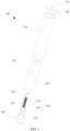
- an electronic cigarette 100 in accordance with a first embodiment includes a housing 120, a mouthpiece 140, a liquid reservoir 150, an atomizing assembly 160, and a power source assembly 180.
- the housing 120 is substantially a hollow elongated cylinder.
- the mouthpiece 140 is located at an end of the housing 120, and the atomizing assembly 160 and the power source 180 are received inside the housing 120. It is to be understood that, the housing 120 may have other shapes, such as rectangular or the like.
- the mouthpiece 140 has thread on its outer periphery, and the mouthpiece 140 is threadedly fixed at the top of the housing 120.
- the mouthpiece 140 defines an air outlet 142 at a center thereof. It should be understood that, the mouthpiece 140 can be omitted.
- the liquid reservoir 150 is substantially a hollow circular tube and is mainly used for storing liquid.
- the liquid reservoir 150 internally defines a substantially cylindrical channel 151 along an axial direction thereof.
- the channel 151 is aligned with the air outlet 142.
- the liquid reservoir 150 is filled with a storage medium 153 for storing liquid.
- the storage medium 153 can be made of fibers, preferably modified fibers, which can remove the odor of the liquid, so as not to affect the taste of the smoke.
- the atomizing assembly 160 includes a liquid absorption element 164, and a heating element 166.
- the liquid absorption element 164 is connected to the liquid reservoir 150.
- the liquid absorption element 164 is shaped as a tube matching with the channel 151. Accordingly, the liquid absorption element 164 can be inserted into the channel 151 of the liquid reservoir 150 and be in direct contact with the storage medium 153.
- the liquid absorption element 164 is made of porous ceramic material with liquid storage and heat-resisting features. Accordingly, the liquid from the storage medium 153 can be uniformly dispersed in the interior and surface of the liquid absorption element 164 by capillary action.
- the porosity of the porous ceramic forming the liquid absorption element 164 is 30% to 60%, preferably 35% to 45%.
- the liquid absorption element 164 defines an internal atomizing passage 165 in an axial direction in communication with the channel 151.
- the liquid absorption element 164 has a liquid absorption surface 1642 contacting the storage medium 153 and configured to absorb the liquid.
- the liquid absorption surface 1642 is an outer circumferential surface of the liquid absorption element 164.
- the liquid absorption element 164 further has an atomizing surface 1652 on the sidewall of the atomizing passage 165.
- the heating element 166 is embedded in an interior of the liquid absorption element 164.
- the heating element 166 is a spiral tubular heating wire, and an edge of the heating element 166 is internally tangent (aligned) to the atomizing surface 1652.
- the heating element 166 is made of a conductive material, such as flexible metals or alloys, preferably nichrome wire.
- the heating element 166 When the heating element 166 is powered, the liquid absorption element 164 can be heated by the heating element 166, such that the liquid stored inside the liquid absorption element 164 will be uniformly heated and atomized into uniform vapor particles (i.e. smoke).
- the smoke enters the atomizing passage 165 through the atomizing surface 1652, and then enters the channel 151, and finally inhaled by the user via the air outlet 142.
- the inner surface of the spiral heating wire since the inner surface of the spiral heating wire is not be in direct contact with the liquid, it can only absorb very few liquid by capillary action or surface tension, which will lead to some problems, such as: a), once the heating wire is powered, the inner side temperature will rise instantaneously, burst sound will be produced upon in contact with the liquid (because the temperature of the liquid is low, the inside temperature of the heating wire is too high); b), during the atomization process, the attached liquid is too little, which results in a great temperature difference between the inner side and the outer side of the spiral heating wire.
- the temperature of the inner side of the heating wire is high, once the liquid is in contact with this hot area, the liquid may be cracked or chemical reaction may take place due to the high temperature, an formaldehyde gas may even be produced; c), when drawing by the user, the airflow temperature is higher due to the direct contact of the airflow with the inner side of the heating wire. Meanwhile, the heat on the inner side of the heating wire is wasted, thus resulting in a lower atomizing efficiency.
- the heating element 166 is completely embedded inside the liquid absorption element 164, and the liquid absorption element 164 composed by porous ceramic is full of liquid, such that the heating element 166 is in complete contact with the liquid, which brings the following advantages: a), the inner surface and the outer surface of the spiral heating wire have a uniform temperature distribution; b), there is less waste of the heat; c), there is no or very few liquid crackle sound; d), no or very few formaldehyde or other harmful substance will be produced.
- the heating element 166 spirally surrounds the atomizing passage 165, and a distance d between the heating element 166 to the atomizing surface 1652 is less than a distance D between the heating element 166 to the liquid absorption surface 1642 of the liquid absorption element 164. Therefore, the liquid absorption surface 1642 of the liquid absorption element 164 composed of porous ceramic has a lower temperature and does not transfer too much heat to the liquid in the liquid reservoir 150, thus avoiding the temperature rise of the liquid which is not atomized. Or else, the energy is wasted on the one hand, and it is on the other hand inconvenient for the user to hold.
- a thermal conductivity of the liquid absorption element is gradually reduced from inside to outside along a radial direction, which can also reduce the surface temperature of the electronic cigarette.
- a method of manufacturing an atomizing assembly includes the following steps:
- the heating wire is sintered and embedded into the liquid absorption element made of porous ceramic, which brings the following advantages: the heating wire can be supported by the liquid absorption element, such that the diameter thereof can be smaller. In the case of the same resistance value, the smaller the diameter, the shorter the length, therefore, the overall volume will be reduced. This on the one hand can save the materials, and more importantly, the components can be miniaturized. The volume of the liquid absorption element wrapping the heating wire can be reduced, thus the rate of temperature rise of the entire liquid absorption element can be increased.
- the liquid absorption element 164 includes a first layer 164a positioned proximately to the atomizing passage 165 and a second layer 164b positioned away from the atomizing passage 165.
- the first layer 164a and the second layer 164b are made of different materials, and the first layer 164a has a higher thermal conductivity than a thermal conductivity of the second layer 164b.
- the heating element 166 is embedded in the first layer 164a of the liquid absorption element 164. This configuration also allows for lowering the temperature of the liquid absorption surface of the liquid absorption element 164, thus saving energy and improving the user experience.
- a method of manufacturing an atomizing assembly includes the following steps:
- the power source 180 includes an electrode holder 184 and a battery (not shown). Both ends of the heating element 166 are coupled to the electrode holder 184 of the power source 180 via two wires 182.
- the battery is used for providing power for the heating element 166.
- the power source 180 may also include conventional elements such as a sensor, an indicator, etc., which are not elaborated herein.
- an electronic cigarette 200 of a second embodiment has a similar structure as that of the electronic cigarette 100 of the first embodiment and includes a housing 220, a mouthpiece 240, a liquid reservoir 250, an atomizing assembly 260, and a power source assembly 280.
- the liquid absorption element 264 is shaped substantially as a circular tube that matches with housing 220.
- the liquid absorption element 264 is received in the housing 220 and is located at an end of the liquid reservoir 250.
- the liquid absorption element 264 has a liquid absorption surface 2642 facing the liquid reservoir 250 and configured to absorb the liquid.
- the liquid from the liquid reservoir 250 can be uniformly dispersed in the interior and surface of the liquid absorption element 264 via the liquid absorption surface 2642 by capillary action.
- the liquid absorption element 264 defines an internal atomizing passage 265 in an axial direction in communication with the channel 251.
- the heating element 266 is a spiral tubular heating wire, which is embedded in an interior of the liquid absorption element 264.
- the heating element 266 spirally surrounds the atomizing passage 265, and an edge of the heating element 266 is internally tangent (aligned) to the atomizing surface 2652.
- the liquid absorption element 264 of the second embodiment is located at the end of the liquid reservoir 250, thus it can facilitate the installation.
- an electronic cigarette 300 of a third embodiment has a similar structure as that of the electronic cigarette 200 of the second embodiment and includes a housing 320, a mouthpiece 340, a liquid reservoir 350, an atomizing assembly 360, and a power source assembly 380.
- the electronic cigarette 300 further includes a reservoir cover 37 positioned between the liquid reservoir 350 and the liquid absorption element 364.
- the reservoir cover 37 is shaped substantially as a round cover and is located at an end of the liquid reservoir 350 to seal the liquid reservoir 350.
- the reservoir cover 37 defines an airflow channel 372 in a middle portion thereof in communication with the channel 351.
- the reservoir cover 37 further defines four liquid conduction channels 374 evenly distributed around the airflow channel 372.
- the liquid absorption element 364 defines an internal atomizing passage 365 in an axial direction in communication with the airflow channel 372.
- the heating element 366 is a spiral tubular heating wire, which is embedded in an interior of the liquid absorption element 364.
- the liquid of the third embodiment can flow into the liquid absorption element 364 via the liquid conduction channels 374, such that the flow of liquid can be more accurately controlled.
- the number of the liquid conduction channels 374 can be three, five or more.
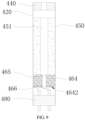
- an electronic cigarette 400 a fourth embodiment is similar to the electronic cigarette 200 of the second embodiment.
- the electronic cigarette 400 includes a housing 420, a mouthpiece 440, a liquid reservoir 450, an atomizing assembly 460, and a power source assembly 480.
- the difference lies in that: the atomizing surface 4642 is an end surface of the liquid absorption element 464 away from the liquid reservoir 450.
- the heating element 466 is a planar spiral heating wire having Archimedes spiral. The heating element 466 is embedded in an interior of the liquid absorption element 464 and is located at an end of the liquid absorption element 464 away from the liquid reservoir 450.
- the heating element 466 spirally surrounds the atomizing passage 465, and an edge of the heating element 466 is internally tangent (aligned) to the atomizing surface 4642.
- the heating element 466 When the heating element 466 is powered, the liquid absorption element 464 can be heated by the heating element 466 from one end thereof, such that the liquid stored inside the liquid absorption element 464 will be uniformly heated and atomized into uniform vapor particles (i.e. smoke).
- the smoke enters the atomizing passage 465 through the atomizing surface 4642, and then enters the channel 451, and finally inhaled by the user via the air outlet.
- a method of manufacturing the aforementioned atomizing assembly includes the following steps:
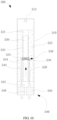
- an electronic cigarette 500 in accordance with a fifth embodiment includes a housing 510, a liquid reservoir 520, an atomizing assembly 530, and a power source assembly 540.
- the liquid reservoir 520, the atomizing assembly 530, and the power source assembly 540 are received in the housing 510.
- the power source assembly 540 is configured to provide power for the atomizing assembly 530.
- the housing 510 has a substantially cylindrical shape, that is, a circular cross section.
- the housing 510 defines a cavity for accommodating each internal element of the electronic cigarette 500.
- the housing 510 is made of plastic.
- the housing 510 can have a rectangular or oval cross-section.
- One end of the housing 510 defines an air outlet 512 at an end thereof and an air inlet (not shown) at the other end thereof.
- the housing 510 has a hollow structure.
- the housing 510 can be provided with a filter nozzle at the end thereof adjacent to the air outlet 512 for filtering nicotine and nicotinamide in the smoke.
- the liquid reservoir 520 is received in the housing 510 and sleeved on the outside of the atomizing assembly 530.
- the liquid reservoir 520 has a cylindrical shape and defines a channel 521 along an axial direction in a middle portion thereof, which is in communication with the air inlet and the air outlet 512.
- the liquid reservoir 520 is internally filled with a liquid storage medium 522 for storing liquid.
- the liquid storage medium 522 can be made of liquid absorbent materials, such as fiber, foam, sponge, foam ceramic, soft rubber or silicon.
- the material forming the liquid reservoir 520 may have elasticity, such that during assembly, the liquid reservoir 520 may be in sufficient contact with the surface of the atomizing assembly 530 by an external force such as pressing. According to the principle of concentration balance, the liquid stored in the liquid reservoir 520 can be delivered to the atomizing assembly 530 with liquid absorbing capability.
- the atomizing assembly 530 is received in the housing 510.
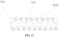
- the atomizing assembly 530 includes a support element 532, a liquid absorption element 533, and a heating element 534.
- the liquid absorption element 533 is disposed on the support element 532 and extends through the support element 532.
- the support element 532 has a hollow cylindrical structure and is received in the channel 521.
- the support element 532 defines an atomizing passage 536 therein in communication with the channel 521 to allow the gas to flow through.
- the support element 532 further defines two aligned through holes 538 on a middle portion of the sidewall thereof, the two through holes 538 are used to support and fix the liquid absorption element 533.
- the through holes 538 are in communication with the atomizing passage 536. It should be understood that, the number of the through holes 538 can be one or more than two.
- the liquid absorption element 533 is shaped substantially as a solid cylinder that matches with the through holes 538. Accordingly, both ends of the liquid absorption element 533 can extend through the through holes 538 of the support element 532, respectively, therefore the liquid absorption element 533 can extend inside the liquid reservoir 520 to be in direct contact with the liquid storage medium 522.
- a middle portion of the liquid absorption element 533 is positioned inside the atomizing passage 536, and the liquid absorption element 533 has an atomizing surface 5332 within the atomizing passage 536.
- the liquid absorption element 533 can be made of a porous ceramic material with liquid storage capability and high temperature resistance. In the illustrated embodiment, the liquid absorption surface of the liquid absorption element 533 are at both ends of the liquid absorption element 533, which include both end surfaces and partial outer circumferential surface.
- the heating element 534 is a spiral tubular heating wire embedded in an interior of the liquid absorption element 533, and the heating wire helically surrounds an axis of the liquid absorption element 533. In the illustrated embodiment, an edge of the heating element 534 is internally tangent (aligned) to the atomizing surface 5332.
- the heating element 534 is made of a conductive material, such as flexible metals or alloys, preferably nichrome wire.
- the heating element 534 When the heating element 534 is powered, the liquid absorption element 533 can be heated by the heating element 534, such that the liquid stored inside the liquid absorption element 533 will be uniformly heated and atomized into uniform vapor particles (i.e. smoke).
- the smoke enters the atomizing passage 536 through the atomizing surface 5332, and then enters the channel 521, and finally inhaled by the user via the air outlet 512.
- the power source assembly 540 is electrically coupled to the heating element 534, so as to provide power for the heating element 534.
- the power supply assembly 540 includes an electrode 542, a conductive wire 544, an electrode holder 546, and a battery (not shown).
- the electrode 542 is electrically coupled to the heating element 534 through the conductive wire 544.
- the electrode 542 is fixed on the electrode holder 546.
- the electrode holder 546 defines an air intake 548 to allow the air to pass through. In an alternative embodiment, the electrode holder 546 can be omitted.
- an electronic cigarette 600 has a similar structure as that of the electronic cigarette 500 of the fifth embodiment and includes a housing 610, a liquid reservoir 620, an atomizing assembly 630, and a power source assembly 640. The difference lies in that:
- the liquid absorption element 533 of the fifth embodiment absorbs and stores liquid in the liquid storage medium 522 mainly through two ends thereof, thus the liquid conduction rate may be relatively slow
- the liquid reservoir 620 of the sixth embodiment directly contains the liquid, and the atomizing assembly 630 is positioned downwardly, and the liquid passage 634 is axially defined in the liquid absorption element 633, such that the contact area with the liquid is increased, thus increasing the liquid conduction rate.
- the configuration how the liquid absorption surface for absorbing liquid and the atomizing surface for the heating element are positioned on the liquid absorption element are not limited hereto.
- the number of the liquid absorption surfaces may be one or more, and the number of the atomizing surfaces may also be one or more.
Description
- The present disclosure relates to an electronic cigarette and a method for manufacturing an atomizing assembly thereof. Related technologies are known from
US 2015/2722218 A1 which describes an atomizing assembly comprising a liquid reservoir defining a channel and a liquid absorption element connected to the liquid reservoir, the liquid absorption element being configured to absorb the liquid, - andEP 2888 963 A1 . which describes an atomizer comprising an atomizing tube and an atomizing assembly arranged in the atomizing tube, the atomizing assembly comprising a ceramic tube and a heating element. - Electronic cigarette, also known as virtual cigarette or electronic atomizers, is a substitute of the cigarette for smoking cessation. The electronic cigarette has a similar appearance and taste as the cigarette, but it generally does not contain other harmful ingredients in the cigarettes, such as tar, suspended particles, and so on.
- The electronic cigarette is usually composed of an atomizer and a power supply assembly. The atomizer is a core unit of the electronic cigarette for generating an atomizing gas, and its atomization effect determines the quality and taste of the smoke. A conventional heating element of the atomizer is a spring-like heating wire, which is fabricated by winding a linear heating wire around a wick. The smoking liquid in the liquid storage device is adsorbed to the wick through both ends of the wick and then heated and atomized by the heating wire. However, the liquid of this type of electronic cigarette is completely absorbed by both ends of the wick and then atomized. Due to the limited area of the end of the wick, the adsorption efficiency of the liquid is quite low Therefore, when a high power heating wire is used, there will be inadequate liquid supply to the wick, thus resulting in dry burning as well as production of a burning smell.
- To address the aforementioned inadequate liquid supply issue, the improvement in the prior art is that the helical heating wire is externally coated with a liquid guiding structure such as liquid guiding cotton, such that the whole sidewall of the liquid guiding cotton can be used to conduct liquid, thus providing adequate liquid supply. However, this approach suffers from some problems, such as: 1) a popping sound by the liquid is often produced; and 2) the atomizing efficiency is low, i.e., the amount of atomized smoke is relatively small at the same power.
- The present invention is defined in the independent claim. It is provided an electronic cigarette with a better atomizing effect.
- An electronic cigarette includes:
- a liquid reservoir configured to store liquid;
- an atomizing assembly received in the housing, the atomizing assembly comprising:
- a liquid absorption element connected to the liquid reservoir, the liquid absorption element being made of porous ceramic, and the liquid absorption element having a liquid absorption surface configured to absorb the liquid, and an atomizing surface; and
- a heating element embedded in an interior of the liquid absorption element, wherein an edge of the heating element is internally tangent to the atomizing surface, and the heating element is configured to atomize the liquid absorbed by the liquid absorption element into atomized gas; and
- a power source assembly received in the housing and connected to the atomizing assembly, the power source assembly being configured to provide power for the heating element.
- A method of manufacturing an atomizing assembly includes:
- providing a positioning element, the positioning element comprising a positioning post;
- winding a heating element spirally around the positioning post;
- placing the positioning post wound with the heating element into a mold, injection molding a first layer of ceramic material on a surface of the heating element and then curing;
- removing the positioning post from the cured first layer of ceramic material; and
- sintering the cured first layer of ceramic material, thus obtaining a liquid absorption element made of porous ceramic and a heating element embedded in an interior of the liquid absorption element.
- An electronic cigarette includes:
- a liquid reservoir received in the housing and configured to store liquid;
- an atomizing assembly received in the housing, the atomizing assembly comprising:
- a support element defining an atomizing passage therein, the support element defining two aligned through holes on a sidewall thereof in communication with the atomizing passage;
- a liquid absorption element made of porous ceramic, wherein both ends of the liquid absorption element extend through the through holes and extend inside the liquid reservoir, the liquid absorption element having a liquid absorption surface configured to absorb the liquid and an atomizing surface located inside the atomizing passage; and
- a heating element embedded in an interior of the liquid absorption element, wherein an edge of the heating element is internally tangent to the atomizing surface, and
- a power source assembly received in the housing and connected to the atomizing assembly, the power source assembly being configured to provide power for the heating element.
- Compared with the prior art, the heating element is completely embedded in an interior of the liquid absorption element, while the liquid absorption element made of porous ceramic is full of liquid, therefore, the heating element is in complete contact with the liquid and achieves a better atomizing effect.
- The above objects, features and advantages of the present invention will become more apparent by describing in detail embodiments thereof with reference to the accompanying drawings. The components in the drawings are not necessarily drawn to scale, the emphasis instead being placed upon clearly illustrating the principles of the present disclosure. Moreover, in the drawings, like reference numerals designate corresponding parts throughout the views.
-
FIG. 1 is a perspective view of an electronic cigarette according to a first embodiment; -
FIG. 2 is a cross-sectional view of the electronic cigarette ofFIG. 1 ; -
FIG. 3A is an enlarged cross-sectional view of an atomizing assembly according to an embodiment; -
FIG. 3B is an enlarged cross-sectional view of an atomizing assembly according to another embodiment; -
FIG. 4 is a perspective view of an electronic cigarette according to a second embodiment; -
FIG. 5 is a cross-sectional view of the electronic cigarette ofFIG. 4 ; -
FIG. 6 is a perspective view of an electronic cigarette according to a third embodiment; -
FIG. 7 is a cross-sectional view of the electronic cigarette ofFIG. 6 ; -
FIG. 8 is a perspective view of an electronic cigarette according to a fourth embodiment; -
FIG. 9 is a cross-sectional view of the electronic cigarette ofFIG. 8 ; -
FIG. 10 is a perspective view of an electronic cigarette according to a fifth embodiment; -
FIG. 11 is an enlarged cross-sectional view of an atomizing assembly ofFIG. 10 ; -
FIG. 12 is a perspective view of an electronic cigarette according to a sixth embodiment; and -
FIG. 13 is a cross-sectional view of the electronic cigarette ofFIG. 12 . - The above and other features of the disclosure including various novel details of construction and combinations of parts, and other advantages, will now be more particularly described with reference to the accompanying drawings and pointed out in the claims. It will be understood that the particular method and device embodying the invention are shown by way of illustration and not as a limitation of the disclosure The principles and features of this disclosure may be employed in various and numerous embodiments without departing from the scope of the disclosure.
- It will be understood that when an element is referred to as being "connected" or "coupled" to another element, it can be directly connected or coupled to the other element or intervening elements may be present. In contrast, if an element is referred to as being "directly connected" or "directly coupled" to another element, there are no intervening elements present. Additionally, the words "herein, ""above," "below" and words of similar import, when used in this application, shall refer to this application as a whole and not to any particular portions of this application.
- Unless otherwise defined, all terms (including technical and scientific terms) used herein have the same meaning as commonly understood by one of ordinary skill in the art to which this invention belongs. It will be further understood that terms, such as those defined in commonly used dictionaries, should be interpreted as having a meaning that is consistent with their meaning in the context of the relevant art and will not be interpreted in an idealized or overly formal sense unless expressly so defined herein.
- Referring to
FIG. 1 andFIG. 2 , anelectronic cigarette 100 in accordance with a first embodiment includes ahousing 120, amouthpiece 140, aliquid reservoir 150, anatomizing assembly 160, and apower source assembly 180. - The
housing 120 is substantially a hollow elongated cylinder. Themouthpiece 140 is located at an end of thehousing 120, and theatomizing assembly 160 and thepower source 180 are received inside thehousing 120. It is to be understood that, thehousing 120 may have other shapes, such as rectangular or the like. - The
mouthpiece 140 has thread on its outer periphery, and themouthpiece 140 is threadedly fixed at the top of thehousing 120. Themouthpiece 140 defines anair outlet 142 at a center thereof. It should be understood that, themouthpiece 140 can be omitted. - The
liquid reservoir 150 is substantially a hollow circular tube and is mainly used for storing liquid. Theliquid reservoir 150 internally defines a substantiallycylindrical channel 151 along an axial direction thereof. Thechannel 151 is aligned with theair outlet 142. Theliquid reservoir 150 is filled with astorage medium 153 for storing liquid. Thestorage medium 153 can be made of fibers, preferably modified fibers, which can remove the odor of the liquid, so as not to affect the taste of the smoke. - The
atomizing assembly 160 includes aliquid absorption element 164, and aheating element 166. - The
liquid absorption element 164 is connected to theliquid reservoir 150. In the illustrated embodiment, theliquid absorption element 164 is shaped as a tube matching with thechannel 151. Accordingly, theliquid absorption element 164 can be inserted into thechannel 151 of theliquid reservoir 150 and be in direct contact with thestorage medium 153. Theliquid absorption element 164 is made of porous ceramic material with liquid storage and heat-resisting features. Accordingly, the liquid from thestorage medium 153 can be uniformly dispersed in the interior and surface of theliquid absorption element 164 by capillary action. The porosity of the porous ceramic forming theliquid absorption element 164 is 30% to 60%, preferably 35% to 45%. If the porosity is too high, the risk of leakage will be increased; if the porosity is too low, there will be insufficient liquid supply and other issues. Theliquid absorption element 164 defines aninternal atomizing passage 165 in an axial direction in communication with thechannel 151. Theliquid absorption element 164 has aliquid absorption surface 1642 contacting thestorage medium 153 and configured to absorb the liquid. In the illustrated embodiment, theliquid absorption surface 1642 is an outer circumferential surface of theliquid absorption element 164. Theliquid absorption element 164 further has anatomizing surface 1652 on the sidewall of theatomizing passage 165. - The
heating element 166 is embedded in an interior of theliquid absorption element 164. In the illustrated embodiment, theheating element 166 is a spiral tubular heating wire, and an edge of theheating element 166 is internally tangent (aligned) to theatomizing surface 1652. Theheating element 166 is made of a conductive material, such as flexible metals or alloys, preferably nichrome wire. When theheating element 166 is powered, theliquid absorption element 164 can be heated by theheating element 166, such that the liquid stored inside theliquid absorption element 164 will be uniformly heated and atomized into uniform vapor particles (i.e. smoke). The smoke enters theatomizing passage 165 through theatomizing surface 1652, and then enters thechannel 151, and finally inhaled by the user via theair outlet 142. - In the conventional electronic cigarette, since the inner surface of the spiral heating wire is not be in direct contact with the liquid, it can only absorb very few liquid by capillary action or surface tension, which will lead to some problems, such as: a), once the heating wire is powered, the inner side temperature will rise instantaneously, burst sound will be produced upon in contact with the liquid (because the temperature of the liquid is low, the inside temperature of the heating wire is too high); b), during the atomization process, the attached liquid is too little, which results in a great temperature difference between the inner side and the outer side of the spiral heating wire. Since the temperature of the inner side of the heating wire is high, once the liquid is in contact with this hot area, the liquid may be cracked or chemical reaction may take place due to the high temperature, an formaldehyde gas may even be produced; c), when drawing by the user, the airflow temperature is higher due to the direct contact of the airflow with the inner side of the heating wire. Meanwhile, the heat on the inner side of the heating wire is wasted, thus resulting in a lower atomizing efficiency. However, in the illustrated embodiment, the
heating element 166 is completely embedded inside theliquid absorption element 164, and theliquid absorption element 164 composed by porous ceramic is full of liquid, such that theheating element 166 is in complete contact with the liquid, which brings the following advantages: a), the inner surface and the outer surface of the spiral heating wire have a uniform temperature distribution; b), there is less waste of the heat; c), there is no or very few liquid crackle sound; d), no or very few formaldehyde or other harmful substance will be produced. - Referring to
FIG. 3A , in one embodiment, theheating element 166 spirally surrounds theatomizing passage 165, and a distance d between theheating element 166 to theatomizing surface 1652 is less than a distance D between theheating element 166 to theliquid absorption surface 1642 of theliquid absorption element 164. Therefore, theliquid absorption surface 1642 of theliquid absorption element 164 composed of porous ceramic has a lower temperature and does not transfer too much heat to the liquid in theliquid reservoir 150, thus avoiding the temperature rise of the liquid which is not atomized. Or else, the energy is wasted on the one hand, and it is on the other hand inconvenient for the user to hold. In an alternative embodiment, a thermal conductivity of the liquid absorption element is gradually reduced from inside to outside along a radial direction, which can also reduce the surface temperature of the electronic cigarette. - According to an embodiment, a method of manufacturing an atomizing assembly includes the following steps:
- In step one, a positioning element is provided, the positioning element has a positioning post.
- In step two, a heating element is wound spirally around the positioning post.
- In step three, the positioning post wound with the heating element is placed into a mold, a first layer of ceramic material is injection molded on a surface of the heating element and then cured.
- In step four, the positioning post is removed from the cured first layer of ceramic material.
- In step five, the cured first layer of ceramic material is sintered, thus a liquid absorption element made of porous ceramic and a heating element embedded in an interior of the liquid absorption element are obtained.
- According to the foregoing method, the heating wire is sintered and embedded into the liquid absorption element made of porous ceramic, which brings the following advantages: the heating wire can be supported by the liquid absorption element, such that the diameter thereof can be smaller. In the case of the same resistance value, the smaller the diameter, the shorter the length, therefore, the overall volume will be reduced. This on the one hand can save the materials, and more importantly, the components can be miniaturized. The volume of the liquid absorption element wrapping the heating wire can be reduced, thus the rate of temperature rise of the entire liquid absorption element can be increased.
- Referring to
FIG. 3B , in an alternative embodiment, theliquid absorption element 164 includes afirst layer 164a positioned proximately to theatomizing passage 165 and asecond layer 164b positioned away from theatomizing passage 165. Thefirst layer 164a and thesecond layer 164b are made of different materials, and thefirst layer 164a has a higher thermal conductivity than a thermal conductivity of thesecond layer 164b. Theheating element 166 is embedded in thefirst layer 164a of theliquid absorption element 164. This configuration also allows for lowering the temperature of the liquid absorption surface of theliquid absorption element 164, thus saving energy and improving the user experience. - According to an embodiment, a method of manufacturing an atomizing assembly includes the following steps:
- In step one, a positioning element is provided, the positioning element has a positioning post.
- In step two, a heating element is wound spirally around the positioning post.
- In step three, the positioning post with the heating element is placed into a mold, a first layer of ceramic material is injection molded on a surface of the heating element and then cured.
- In step four, a second layer of ceramic material is injected on the surface of the first layer of ceramic material and then cured. The first layer of ceramic material has a higher thermal conductivity than a thermal conductivity of the second layer of ceramic material.
- In step five, the positioning post is removed from the cured first and second layers of ceramic material.
- In step six, the cured first and second layers of ceramic material are sintered, thus a liquid absorption element made of porous ceramic and a heating element embedded in an interior of the liquid absorption element are obtained.
- Referring to
FIG. 1 , thepower source 180 includes anelectrode holder 184 and a battery (not shown). Both ends of theheating element 166 are coupled to theelectrode holder 184 of thepower source 180 via twowires 182. The battery is used for providing power for theheating element 166. It is to be understood that, thepower source 180 may also include conventional elements such as a sensor, an indicator, etc., which are not elaborated herein. - Referring to
FIG. 4 andFIG. 5 , anelectronic cigarette 200 of a second embodiment has a similar structure as that of theelectronic cigarette 100 of the first embodiment and includes ahousing 220, amouthpiece 240, aliquid reservoir 250, anatomizing assembly 260, and apower source assembly 280. The differences lie in that: in the illustrated embodiment, theliquid absorption element 264 is shaped substantially as a circular tube that matches withhousing 220. Theliquid absorption element 264 is received in thehousing 220 and is located at an end of theliquid reservoir 250. Theliquid absorption element 264 has aliquid absorption surface 2642 facing theliquid reservoir 250 and configured to absorb the liquid. The liquid from theliquid reservoir 250 can be uniformly dispersed in the interior and surface of theliquid absorption element 264 via theliquid absorption surface 2642 by capillary action. Theliquid absorption element 264 defines aninternal atomizing passage 265 in an axial direction in communication with the channel 251. Theheating element 266 is a spiral tubular heating wire, which is embedded in an interior of theliquid absorption element 264. Theheating element 266 spirally surrounds theatomizing passage 265, and an edge of theheating element 266 is internally tangent (aligned) to the atomizing surface 2652. Compared with the first embodiment, theliquid absorption element 264 of the second embodiment is located at the end of theliquid reservoir 250, thus it can facilitate the installation. - Referring to
FIG. 6 andFIG. 7 , anelectronic cigarette 300 of a third embodiment has a similar structure as that of theelectronic cigarette 200 of the second embodiment and includes ahousing 320, amouthpiece 340, aliquid reservoir 350, anatomizing assembly 360, and apower source assembly 380. The differences lie in that: theelectronic cigarette 300 further includes areservoir cover 37 positioned between theliquid reservoir 350 and theliquid absorption element 364. Thereservoir cover 37 is shaped substantially as a round cover and is located at an end of theliquid reservoir 350 to seal theliquid reservoir 350. Thereservoir cover 37 defines anairflow channel 372 in a middle portion thereof in communication with thechannel 351. Thereservoir cover 37 further defines fourliquid conduction channels 374 evenly distributed around theairflow channel 372. No liquid medium is provided in thereservoir 350, and the liquid in theliquid reservoir 350 can flow into theliquid absorption element 364 via the fourliquid conduction channels 374. Theliquid absorption element 364 defines aninternal atomizing passage 365 in an axial direction in communication with theairflow channel 372. Theheating element 366 is a spiral tubular heating wire, which is embedded in an interior of theliquid absorption element 364. Compared with the second embodiment, the liquid of the third embodiment can flow into theliquid absorption element 364 via theliquid conduction channels 374, such that the flow of liquid can be more accurately controlled. It should be noted that, the number of theliquid conduction channels 374 can be three, five or more. - Referring to
FIG. 8 andFIG. 9 , an electronic cigarette 400 a fourth embodiment is similar to theelectronic cigarette 200 of the second embodiment. Theelectronic cigarette 400 includes ahousing 420, amouthpiece 440, aliquid reservoir 450, anatomizing assembly 460, and apower source assembly 480. The difference lies in that: theatomizing surface 4642 is an end surface of theliquid absorption element 464 away from theliquid reservoir 450. Theheating element 466 is a planar spiral heating wire having Archimedes spiral. Theheating element 466 is embedded in an interior of theliquid absorption element 464 and is located at an end of theliquid absorption element 464 away from theliquid reservoir 450. Theheating element 466 spirally surrounds theatomizing passage 465, and an edge of theheating element 466 is internally tangent (aligned) to theatomizing surface 4642. When theheating element 466 is powered, theliquid absorption element 464 can be heated by theheating element 466 from one end thereof, such that the liquid stored inside theliquid absorption element 464 will be uniformly heated and atomized into uniform vapor particles (i.e. smoke). The smoke enters theatomizing passage 465 through theatomizing surface 4642, and then enters thechannel 451, and finally inhaled by the user via the air outlet. - In one embodiment, a method of manufacturing the aforementioned atomizing assembly includes the following steps:
- In step one, a positioning element is provided. The positioning element includes a positioning surface and a positioning post located on the positioning surface.
- In step two, a heating element being a planar helical heating wire is placed on the positioning surface and surrounds the positioning post;
- In step three, the positioning post with the heating element is placed into a mold, a first layer of ceramic material is injection molded on a surface of the heating element and then cured;
- In step four, the positioning post is removed from the cured first layer of ceramic material;
- In step five, the cured first layer of ceramic material is sintered, thus obtaining a liquid absorption element made of porous ceramic and a heating element embedded at an end of the liquid absorption element.
- Referring to
FIG. 10 , anelectronic cigarette 500 in accordance with a fifth embodiment includes ahousing 510, aliquid reservoir 520, anatomizing assembly 530, and apower source assembly 540. Theliquid reservoir 520, theatomizing assembly 530, and thepower source assembly 540 are received in thehousing 510. Thepower source assembly 540 is configured to provide power for theatomizing assembly 530. - The
housing 510 has a substantially cylindrical shape, that is, a circular cross section. Thehousing 510 defines a cavity for accommodating each internal element of theelectronic cigarette 500. Thehousing 510 is made of plastic. In alternative embodiments, thehousing 510 can have a rectangular or oval cross-section. One end of thehousing 510 defines anair outlet 512 at an end thereof and an air inlet (not shown) at the other end thereof. Thehousing 510 has a hollow structure. Thehousing 510 can be provided with a filter nozzle at the end thereof adjacent to theair outlet 512 for filtering nicotine and nicotinamide in the smoke. - The
liquid reservoir 520 is received in thehousing 510 and sleeved on the outside of theatomizing assembly 530. In the illustrated embodiment, theliquid reservoir 520 has a cylindrical shape and defines achannel 521 along an axial direction in a middle portion thereof, which is in communication with the air inlet and theair outlet 512. Theliquid reservoir 520 is internally filled with aliquid storage medium 522 for storing liquid. Theliquid storage medium 522 can be made of liquid absorbent materials, such as fiber, foam, sponge, foam ceramic, soft rubber or silicon. The material forming theliquid reservoir 520 may have elasticity, such that during assembly, theliquid reservoir 520 may be in sufficient contact with the surface of theatomizing assembly 530 by an external force such as pressing. According to the principle of concentration balance, the liquid stored in theliquid reservoir 520 can be delivered to theatomizing assembly 530 with liquid absorbing capability. - The
atomizing assembly 530 is received in thehousing 510. Theatomizing assembly 530 includes asupport element 532, aliquid absorption element 533, and aheating element 534. Theliquid absorption element 533 is disposed on thesupport element 532 and extends through thesupport element 532. - The
support element 532 has a hollow cylindrical structure and is received in thechannel 521. Thesupport element 532 defines anatomizing passage 536 therein in communication with thechannel 521 to allow the gas to flow through. Thesupport element 532 further defines two aligned throughholes 538 on a middle portion of the sidewall thereof, the two throughholes 538 are used to support and fix theliquid absorption element 533. The throughholes 538 are in communication with theatomizing passage 536. It should be understood that, the number of the throughholes 538 can be one or more than two. - Referring to
FIG. 11 , theliquid absorption element 533 is shaped substantially as a solid cylinder that matches with the throughholes 538. Accordingly, both ends of theliquid absorption element 533 can extend through the throughholes 538 of thesupport element 532, respectively, therefore theliquid absorption element 533 can extend inside theliquid reservoir 520 to be in direct contact with theliquid storage medium 522. A middle portion of theliquid absorption element 533 is positioned inside theatomizing passage 536, and theliquid absorption element 533 has anatomizing surface 5332 within theatomizing passage 536. Theliquid absorption element 533 can be made of a porous ceramic material with liquid storage capability and high temperature resistance. In the illustrated embodiment, the liquid absorption surface of theliquid absorption element 533 are at both ends of theliquid absorption element 533, which include both end surfaces and partial outer circumferential surface. - The
heating element 534 is a spiral tubular heating wire embedded in an interior of theliquid absorption element 533, and the heating wire helically surrounds an axis of theliquid absorption element 533. In the illustrated embodiment, an edge of theheating element 534 is internally tangent (aligned) to theatomizing surface 5332. Theheating element 534 is made of a conductive material, such as flexible metals or alloys, preferably nichrome wire. When theheating element 534 is powered, theliquid absorption element 533 can be heated by theheating element 534, such that the liquid stored inside theliquid absorption element 533 will be uniformly heated and atomized into uniform vapor particles (i.e. smoke). The smoke enters theatomizing passage 536 through theatomizing surface 5332, and then enters thechannel 521, and finally inhaled by the user via theair outlet 512. - Referring to
FIG. 10 , thepower source assembly 540 is electrically coupled to theheating element 534, so as to provide power for theheating element 534. In the illustrated embodiment, thepower supply assembly 540 includes anelectrode 542, aconductive wire 544, anelectrode holder 546, and a battery (not shown). Theelectrode 542 is electrically coupled to theheating element 534 through theconductive wire 544. Theelectrode 542 is fixed on theelectrode holder 546. Theelectrode holder 546 defines anair intake 548 to allow the air to pass through. In an alternative embodiment, theelectrode holder 546 can be omitted. - Referring to
FIG. 12 andFIG. 13 , anelectronic cigarette 600 according to a sixth embodiment has a similar structure as that of theelectronic cigarette 500 of the fifth embodiment and includes ahousing 610, aliquid reservoir 620, anatomizing assembly 630, and apower source assembly 640. The difference lies in that: - (1) No storage medium is filled in the
liquid reservoir 620, and the liquid is directly stored in theliquid reservoir 620. - (2) The
liquid absorption element 633 is located at a position of thesupport element 632 adjacent to thepower source assembly 640. - (3) The
liquid absorption element 633 has a tubular tube shape and axially defines aliquid passage 635 therein. The atomizing surface is an outer circumferential surface of theliquid absorption element 633, and the liquid absorption surface is an inner circumferential surface of theliquid absorption element 633, i.e., the liquid absorption surface is a sidewall of theliquid passage 635. - The
liquid absorption element 533 of the fifth embodiment absorbs and stores liquid in theliquid storage medium 522 mainly through two ends thereof, thus the liquid conduction rate may be relatively slow Theliquid reservoir 620 of the sixth embodiment directly contains the liquid, and theatomizing assembly 630 is positioned downwardly, and the liquid passage 634 is axially defined in theliquid absorption element 633, such that the contact area with the liquid is increased, thus increasing the liquid conduction rate. - Although the respective embodiments have been described one by one, it shall be appreciated that the respective embodiments will not be isolated. Those skilled in the art can apparently appreciate upon reading the disclosure of this application that the respective technical features involved in the respective embodiments can be combined arbitrarily between the respective embodiments as long as they have no collision with each other. Of course, the respective technical features mentioned in the same embodiment can also be combined arbitrarily as long as they have no collision with each other.
- It should be noted that, the configuration how the liquid absorption surface for absorbing liquid and the atomizing surface for the heating element are positioned on the liquid absorption element are not limited hereto. The number of the liquid absorption surfaces may be one or more, and the number of the atomizing surfaces may also be one or more.
Claims (7)
- An atomizing assembly (160) for an electronic cigarette (100), comprising:a liquid absorption element (164) made of porous ceramic, the liquid absorption element (164) having a liquid absorption surface (1642) configured to absorb liquid, and an atomizing surface (1652); anda heating element (166) configured to atomize the liquid absorbed by the liquid absorption element (164) into atomized gas;wherein the liquid absorption element (164) has a tubular shape, the liquid absorption element (164) defines an atomizing passage (165) therein, the atomizing surface (1652) is a sidewall of the atomizing passage (165), the liquid absorption element (164) comprises a first layer (164a) proximately to the atomizing passage (165) and a second layer (164b) away from the atomizing passage (165), the first layer (164a) has a higher thermal conductivity than a thermal conductivity of the second layer(164b), the heating element (166) is embedded in the first layer (164a) of the liquid absorption element (164).
- The atomizing assembly (160) according to claim 1, characterized in that the heating element (166) is a spiral tubular heating wire, which spirally surrounds the atomizing passage (165), an edge of the heating element (166) is internally tangent to the atomizing surface (1652).
- The atomizing assembly (160) according to claim 1, characterized in that a distance between the heating wire (166) to the atomizing surface (1652) is less than a distance between the heating wire (166) to the liquid absorption surface (1642) of the liquid absorption element (164).
- The atomizing assembly (160) according to claim 1, characterized in that the porous ceramic has a porosity of 30% to 60%.
- The atomizing assembly (160) according to claim 1, characterized in that the liquid absorption surface (1642) is an outer circumferential surface of the liquid absorption element (164).
- An electronic cigarette (100), comprising:a liquid reservoir (150) configured to store liquid;the atomizing assembly (160) according to anyone of claim 1 to 5; anda power source assembly (180) connected to the atomizing assembly (160), the power source assembly (180) being configured to provide power for the heating element (166).
- The electronic cigarette (100) according to claim 6, characterized in that the liquid absorption element (164) is located at an end of the liquid reservoir (150), the liquid absorption surface (1642) is an end surface of the liquid absorption element (164) facing the liquid reservoir (150).
Priority Applications (1)
| Application Number | Priority Date | Filing Date | Title |
|---|---|---|---|
| EP20189173.6A EP3760067B1 (en) | 2015-10-21 | 2015-10-21 | Electronic cigarette |
Applications Claiming Priority (4)
| Application Number | Priority Date | Filing Date | Title |
|---|---|---|---|
| EP15906456.7A EP3292773B1 (en) | 2015-10-21 | 2015-10-21 | Electronic cigarette and method for manufacturing atomizing assembly thereof |
| EP20189173.6A EP3760067B1 (en) | 2015-10-21 | 2015-10-21 | Electronic cigarette |
| EP19208468.9A EP3685687B1 (en) | 2015-10-21 | 2015-10-21 | Electronic cigarette |
| PCT/CN2015/092421 WO2017066938A1 (en) | 2015-10-21 | 2015-10-21 | Electronic cigarette and method for manufacturing atomizing assembly thereof |
Related Parent Applications (4)
| Application Number | Title | Priority Date | Filing Date |
|---|---|---|---|
| EP19208468.9A Division EP3685687B1 (en) | 2015-10-21 | 2015-10-21 | Electronic cigarette |
| EP19208468.9A Previously-Filed-Application EP3685687B1 (en) | 2015-10-21 | 2015-10-21 | Electronic cigarette |
| EP19208468.9A Division-Into EP3685687B1 (en) | 2015-10-21 | 2015-10-21 | Electronic cigarette |
| EP15906456.7A Division EP3292773B1 (en) | 2015-10-21 | 2015-10-21 | Electronic cigarette and method for manufacturing atomizing assembly thereof |
Publications (2)
| Publication Number | Publication Date |
|---|---|
| EP3760067A1 EP3760067A1 (en) | 2021-01-06 |
| EP3760067B1 true EP3760067B1 (en) | 2023-08-23 |
Family
ID=58556567
Family Applications (3)
| Application Number | Title | Priority Date | Filing Date |
|---|---|---|---|
| EP20189173.6A Active EP3760067B1 (en) | 2015-10-21 | 2015-10-21 | Electronic cigarette |
| EP19208468.9A Active EP3685687B1 (en) | 2015-10-21 | 2015-10-21 | Electronic cigarette |
| EP15906456.7A Active EP3292773B1 (en) | 2015-10-21 | 2015-10-21 | Electronic cigarette and method for manufacturing atomizing assembly thereof |
Family Applications After (2)
| Application Number | Title | Priority Date | Filing Date |
|---|---|---|---|
| EP19208468.9A Active EP3685687B1 (en) | 2015-10-21 | 2015-10-21 | Electronic cigarette |
| EP15906456.7A Active EP3292773B1 (en) | 2015-10-21 | 2015-10-21 | Electronic cigarette and method for manufacturing atomizing assembly thereof |
Country Status (3)
| Country | Link |
|---|---|
| US (4) | US10791762B2 (en) |
| EP (3) | EP3760067B1 (en) |
| WO (1) | WO2017066938A1 (en) |
Families Citing this family (43)
| Publication number | Priority date | Publication date | Assignee | Title |
|---|---|---|---|---|
| US20160345631A1 (en) | 2005-07-19 | 2016-12-01 | James Monsees | Portable devices for generating an inhalable vapor |
| US10638792B2 (en) | 2013-03-15 | 2020-05-05 | Juul Labs, Inc. | Securely attaching cartridges for vaporizer devices |
| US10279934B2 (en) | 2013-03-15 | 2019-05-07 | Juul Labs, Inc. | Fillable vaporizer cartridge and method of filling |
| US20160366947A1 (en) | 2013-12-23 | 2016-12-22 | James Monsees | Vaporizer apparatus |
| US10058129B2 (en) | 2013-12-23 | 2018-08-28 | Juul Labs, Inc. | Vaporization device systems and methods |
| US10159282B2 (en) | 2013-12-23 | 2018-12-25 | Juul Labs, Inc. | Cartridge for use with a vaporizer device |
| DE202014011221U1 (en) | 2013-12-23 | 2018-09-13 | Juul Labs Uk Holdco Limited | Systems for an evaporation device |
| USD842536S1 (en) | 2016-07-28 | 2019-03-05 | Juul Labs, Inc. | Vaporizer cartridge |
| USD825102S1 (en) | 2016-07-28 | 2018-08-07 | Juul Labs, Inc. | Vaporizer device with cartridge |
| US10076139B2 (en) | 2013-12-23 | 2018-09-18 | Juul Labs, Inc. | Vaporizer apparatus |
| AU2015357509B2 (en) | 2014-12-05 | 2021-05-20 | Juul Labs, Inc. | Calibrated dose control |
| US10834965B2 (en) * | 2016-01-20 | 2020-11-17 | Shenzhen Kanger Technology Co., Ltd. | Ceramic vaporizer and electronic cigarettes having the ceramic vaporizer |
| CA2920973C (en) * | 2016-01-26 | 2018-09-18 | Xiaochun Zhu | Ceramic vaporizer with replaceable e-liquid storage medium and electronic cigarettes having the same |
| WO2017139595A1 (en) | 2016-02-11 | 2017-08-17 | Pax Labs, Inc. | Fillable vaporizer cartridge and method of filling |
| US10405582B2 (en) | 2016-03-10 | 2019-09-10 | Pax Labs, Inc. | Vaporization device with lip sensing |
| USD849996S1 (en) | 2016-06-16 | 2019-05-28 | Pax Labs, Inc. | Vaporizer cartridge |
| USD851830S1 (en) | 2016-06-23 | 2019-06-18 | Pax Labs, Inc. | Combined vaporizer tamp and pick tool |
| USD836541S1 (en) | 2016-06-23 | 2018-12-25 | Pax Labs, Inc. | Charging device |
| CN205865985U (en) * | 2016-08-02 | 2017-01-11 | 卓尔悦欧洲控股有限公司 | Atomising head, atomizing device and electron cigarette |
| CN206423562U (en) * | 2016-11-28 | 2017-08-22 | 深圳市艾维普思科技股份有限公司 | Electronic cigarette and its double-deck oil-bearing structure |
| WO2018111843A1 (en) | 2016-12-12 | 2018-06-21 | Vmr Products Llc | Vaporizer cartridge |
| US10701977B2 (en) * | 2017-08-09 | 2020-07-07 | Vuber Technologies, Inc. | Permeable element based vaporization process and device |
| USD887632S1 (en) | 2017-09-14 | 2020-06-16 | Pax Labs, Inc. | Vaporizer cartridge |
| WO2019157651A1 (en) | 2018-02-13 | 2019-08-22 | 深圳麦克韦尔股份有限公司 | Electronic cigarette and heating assembly and heating member thereof |
| US20200367564A1 (en) * | 2018-02-13 | 2020-11-26 | Shenzhen Smoore Technology Limited | Electronic cigarette and heating assembly and heating member thereof |
| JP2021525093A (en) * | 2018-05-31 | 2021-09-24 | ジェイティー インターナショナル エス.エイ.JT International S.A. | Aerosol-generating articles, aerosol-generating systems, and methods for generating flavored aerosols. |
| EP3813914B1 (en) * | 2018-06-26 | 2023-10-25 | Juul Labs, Inc. | Vaporizer wicking elements |
| US11413409B2 (en) | 2018-09-12 | 2022-08-16 | Juul Labs, Inc. | Vaporizer including positive temperature coefficient of resistivity (PTCR) heating element |
| CN108968160B (en) * | 2018-09-14 | 2024-03-05 | 深圳麦克韦尔科技有限公司 | Electronic cigarette, atomization assembly and atomization assembly manufacturing method |
| WO2020069432A1 (en) * | 2018-09-27 | 2020-04-02 | JJ&J Industry's LLC | Vaporizer cartridge system |
| US11439774B2 (en) * | 2018-11-05 | 2022-09-13 | Juul Labs, Inc. | Vaporizer devices and cartridges with folded mesh |
| CN109349680A (en) * | 2018-11-15 | 2019-02-19 | 深圳市合元科技有限公司 | Porous heater, the atomizer comprising porous heater and porous preparation |
| US11730201B2 (en) | 2019-04-15 | 2023-08-22 | Vaporous Technologies, Inc. | Personal vaporizer having a heating element with multiple surfaces |
| US11839238B2 (en) | 2019-05-15 | 2023-12-12 | Vaporous Technologies, Inc. | Personal vaporizer and method for filling same |
| CN112167725B (en) * | 2019-07-03 | 2023-03-14 | 深圳市合元科技有限公司 | Application of organic porous material in aerosol generating device and atomizer using material |
| CN211482973U (en) * | 2019-11-26 | 2020-09-15 | 深圳市合元科技有限公司 | Atomization component and electronic cigarette |
| CN111493368A (en) * | 2020-04-23 | 2020-08-07 | 同济大学 | Porous ceramic fin type electronic cigarette |
| US11839239B2 (en) | 2020-08-12 | 2023-12-12 | DES Products Ltd. | Adjustable airflow cartridge for electronic vaporizer |
| CN112618880B (en) * | 2020-11-09 | 2022-12-16 | 哈尔滨工业大学(深圳) | Liquid atomization device and preparation method |
| CN215347030U (en) * | 2021-05-25 | 2021-12-31 | 深圳市合元科技有限公司 | Atomizer and electronic atomization device |
| CN113462030A (en) * | 2021-06-23 | 2021-10-01 | 深圳市华诚达精密工业有限公司 | Fiber elastic atomizing core and preparation method thereof |
| US11533950B1 (en) | 2022-02-09 | 2022-12-27 | Clear IP Corporation | Atomizer cartridge with integrally formed internal fluid reservoir and mouthpiece portion |
| CN115007385A (en) * | 2022-07-19 | 2022-09-06 | 东莞市克莱鹏雾化科技有限公司 | Packaging structure and atomizing device of atomizing piece |
Family Cites Families (27)
| Publication number | Priority date | Publication date | Assignee | Title |
|---|---|---|---|---|
| CN201379072Y (en) * | 2009-02-11 | 2010-01-13 | 韩力 | Improved atomizing electronic cigarette |
| US9498588B2 (en) * | 2011-12-14 | 2016-11-22 | Atmos Nation, LLC | Portable pen sized electric herb vaporizer with ceramic heating chamber |
| WO2013110211A1 (en) | 2012-01-25 | 2013-08-01 | Maas Bernard Karel | Electronic simulation cigarette and atomizer thereof |
| US9326547B2 (en) * | 2012-01-31 | 2016-05-03 | Altria Client Services Llc | Electronic vaping article |
| CN103491814B (en) * | 2012-02-03 | 2017-08-25 | 富特姆控股有限责任公司 | A kind of electronic simulation cigarette and its atomizer |
| US20130255675A1 (en) * | 2012-04-01 | 2013-10-03 | Huizhou Kimree Technology Co., Ltd. | Electronic Cigarette and Mouthpiece Part Thereof |
| GB2504074A (en) * | 2012-07-16 | 2014-01-22 | Nicoventures Holdings Ltd | Electronic cigarette |
| US10278430B2 (en) * | 2012-09-10 | 2019-05-07 | Healthier Choices Management Corp. | Electronic pipe with modified heat source |
| US20140150785A1 (en) * | 2012-12-05 | 2014-06-05 | Vire, L.L.C. | Electronic cigarette or inhaler |
| CN103960782B (en) | 2013-09-29 | 2016-09-21 | 深圳麦克韦尔股份有限公司 | Electronic cigarette |
| US9861132B2 (en) * | 2013-12-31 | 2018-01-09 | Shenzhen First Union Technology Co., Ltd. | Atomizer and electronic cigarette having same |
| CN203762290U (en) | 2013-12-31 | 2014-08-13 | 深圳市合元科技有限公司 | Atomizer for electronic cigarette and electronic cigarette |
| CN103859604B (en) * | 2014-01-23 | 2017-05-31 | 深圳市康尔科技有限公司 | The heat generating component and atomization structure of electronic cigarette |
| WO2015143666A1 (en) * | 2014-03-27 | 2015-10-01 | 深圳麦克韦尔股份有限公司 | Electronic cigarette |
| CN103948174B (en) * | 2014-03-27 | 2017-08-08 | 深圳麦克韦尔股份有限公司 | Electronic cigarette |
| CN204217916U (en) | 2014-10-28 | 2015-03-25 | 深圳市麦克韦尔科技有限公司 | Electronic cigarette and atomizing component thereof |
| CN204104843U (en) | 2014-10-31 | 2015-01-21 | 朱晓春 | Electronic smoke atomizer electro-heat equipment |
| CN204483035U (en) * | 2015-04-01 | 2015-07-22 | 湖北中烟工业有限责任公司 | Porous ceramics atomizer and there is the electronic cigarette of this porous ceramics atomizer |
| CN104824853B (en) * | 2015-04-22 | 2018-12-04 | 卓尔悦欧洲控股有限公司 | Atomizer and its aerosol generating device |
| WO2017000239A1 (en) * | 2015-06-30 | 2017-01-05 | 深圳麦克韦尔股份有限公司 | Electronic cigarette, atomization device thereof and assembling method of atomization device |
| CN204994622U (en) * | 2015-09-10 | 2016-01-27 | 深圳市合元科技有限公司 | Atomizer and electronic cigarette |
| CN105310114B (en) | 2015-10-21 | 2018-08-17 | 深圳麦克韦尔股份有限公司 | The manufacturing method of electronic cigarette and its atomizing component |
| CN205266968U (en) | 2015-10-21 | 2016-06-01 | 深圳麦克韦尔股份有限公司 | Electronic cigarette |
| EP3188570B1 (en) * | 2016-04-22 | 2019-09-11 | Shenzhen First Union Technology Co., Ltd. | Atomizer of electronic cigarette, ceramic heating atomizing core and ceramic heater therein |
| GB2561867B (en) * | 2017-04-25 | 2021-04-07 | Nerudia Ltd | Aerosol delivery system |
| US10524518B1 (en) * | 2017-09-25 | 2020-01-07 | Brett William Tygett | Dual coil vaporizer inhalation cartridge for high viscosity oil or resin |
| CN109105958A (en) * | 2018-08-17 | 2019-01-01 | 深圳市合元科技有限公司 | Heat generating component, atomization core, atomizer and electronic cigarette |
-
2015
- 2015-10-21 US US15/740,657 patent/US10791762B2/en active Active
- 2015-10-21 WO PCT/CN2015/092421 patent/WO2017066938A1/en unknown
- 2015-10-21 EP EP20189173.6A patent/EP3760067B1/en active Active
- 2015-10-21 EP EP19208468.9A patent/EP3685687B1/en active Active
- 2015-10-21 EP EP15906456.7A patent/EP3292773B1/en active Active
-
2020
- 2020-08-27 US US17/004,215 patent/US11266798B2/en active Active
- 2020-08-27 US US17/004,123 patent/US11446452B2/en active Active
-
2022
- 2022-08-17 US US17/889,548 patent/US11918738B2/en active Active
Also Published As
| Publication number | Publication date |
|---|---|
| US11266798B2 (en) | 2022-03-08 |
| US20220387739A1 (en) | 2022-12-08 |
| EP3685687A1 (en) | 2020-07-29 |
| EP3760067A1 (en) | 2021-01-06 |
| US20200390151A1 (en) | 2020-12-17 |
| EP3292773A4 (en) | 2019-01-16 |
| EP3685687B1 (en) | 2023-06-14 |
| US20180184714A1 (en) | 2018-07-05 |
| EP3292773A1 (en) | 2018-03-14 |
| US11446452B2 (en) | 2022-09-20 |
| US10791762B2 (en) | 2020-10-06 |
| EP3292773B1 (en) | 2020-01-29 |
| WO2017066938A1 (en) | 2017-04-27 |
| US20200390152A1 (en) | 2020-12-17 |
| US11918738B2 (en) | 2024-03-05 |
Similar Documents
| Publication | Publication Date | Title |
|---|---|---|
| US11918738B2 (en) | Electronic cigarette and method for manufacturing atomizing assembly thereof | |
| EP3127437B1 (en) | Electronic cigarette | |
| US11707091B2 (en) | Atomizing nozzle and electronic atomizing inhaler | |
| US9572373B2 (en) | Electronic cigarette | |
| US20220304117A1 (en) | Electronic Cigarette and Atomizing Assembly and Atomizing Element Thereof | |
| RU2709971C1 (en) | Electronic device for steam production | |
| CN105310114B (en) | The manufacturing method of electronic cigarette and its atomizing component | |
| TWI612908B (en) | Method for manufacturing atomization unit and atomization unit | |
| US10980284B2 (en) | Electronic cigarette atomizer employing vertical ceramic atomizing unit | |
| RU2678817C2 (en) | Aerosol-generating devices incorporating intertwined wick and heating element | |
| TWI643564B (en) | Atomizing unit | |
| US20140109921A1 (en) | Electronic cigarette | |
| WO2016169115A1 (en) | Atomizer and aerosol generation device thereof | |
| WO2017156696A1 (en) | Electronic cigarette atomizer and forming device for heat generating body thereof, and method for manufacturing heat generating body | |
| CN103948174A (en) | Electronic cigarette | |
| CN205266968U (en) | Electronic cigarette | |
| CN108968160B (en) | Electronic cigarette, atomization assembly and atomization assembly manufacturing method | |
| JP7382482B2 (en) | Cartridge for aerosol generation system | |
| TWI642367B (en) | Atomizing unit | |
| CN216983566U (en) | Atomizing device and corresponding electronic cigarette | |
| RU2787774C2 (en) | Aerosol forming devices containing mutually intertwined wick and heating element | |
| CN114747809A (en) | Heating core, electronic cigarette and heating wire manufacturing method |
Legal Events
| Date | Code | Title | Description |
|---|---|---|---|
| PUAI | Public reference made under article 153(3) epc to a published international application that has entered the european phase |
Free format text: ORIGINAL CODE: 0009012 |
|
| STAA | Information on the status of an ep patent application or granted ep patent |
Free format text: STATUS: THE APPLICATION HAS BEEN PUBLISHED |
|
| AC | Divisional application: reference to earlier application |
Ref document number: 3685687 Country of ref document: EP Kind code of ref document: P Ref document number: 3292773 Country of ref document: EP Kind code of ref document: P |
|
| AK | Designated contracting states |
Kind code of ref document: A1 Designated state(s): AL AT BE BG CH CY CZ DE DK EE ES FI FR GB GR HR HU IE IS IT LI LT LU LV MC MK MT NL NO PL PT RO RS SE SI SK SM TR |
|
| STAA | Information on the status of an ep patent application or granted ep patent |
Free format text: STATUS: REQUEST FOR EXAMINATION WAS MADE |
|
| 17P | Request for examination filed |
Effective date: 20210222 |
|
| RBV | Designated contracting states (corrected) |
Designated state(s): AL AT BE BG CH CY CZ DE DK EE ES FI FR GB GR HR HU IE IS IT LI LT LU LV MC MK MT NL NO PL PT RO RS SE SI SK SM TR |
|
| REG | Reference to a national code |
Ref country code: DE Ref legal event code: R079 Ref document number: 602015085354 Country of ref document: DE Free format text: PREVIOUS MAIN CLASS: A24F0047000000 Ipc: A24F0040440000 Ref country code: DE Ref legal event code: R079 Free format text: PREVIOUS MAIN CLASS: A24F0047000000 Ipc: A24F0040440000 |
|
| GRAP | Despatch of communication of intention to grant a patent |
Free format text: ORIGINAL CODE: EPIDOSNIGR1 |
|
| STAA | Information on the status of an ep patent application or granted ep patent |
Free format text: STATUS: GRANT OF PATENT IS INTENDED |
|
| RIC1 | Information provided on ipc code assigned before grant |
Ipc: A61M 11/04 20060101ALI20230213BHEP Ipc: A61M 15/06 20060101ALI20230213BHEP Ipc: A24F 40/70 20200101ALI20230213BHEP Ipc: A24F 40/46 20200101ALI20230213BHEP Ipc: A24F 40/44 20200101AFI20230213BHEP |
|
| INTG | Intention to grant announced |
Effective date: 20230316 |
|
| GRAS | Grant fee paid |
Free format text: ORIGINAL CODE: EPIDOSNIGR3 |
|
| P01 | Opt-out of the competence of the unified patent court (upc) registered |
Effective date: 20230601 |
|
| GRAA | (expected) grant |
Free format text: ORIGINAL CODE: 0009210 |
|
| STAA | Information on the status of an ep patent application or granted ep patent |
Free format text: STATUS: THE PATENT HAS BEEN GRANTED |
|
| AC | Divisional application: reference to earlier application |
Ref document number: 3292773 Country of ref document: EP Kind code of ref document: P Ref document number: 3685687 Country of ref document: EP Kind code of ref document: P |
|
| AK | Designated contracting states |
Kind code of ref document: B1 Designated state(s): AL AT BE BG CH CY CZ DE DK EE ES FI FR GB GR HR HU IE IS IT LI LT LU LV MC MK MT NL NO PL PT RO RS SE SI SK SM TR |
|
| REG | Reference to a national code |
Ref country code: GB Ref legal event code: FG4D |
|
| REG | Reference to a national code |
Ref country code: CH Ref legal event code: EP |
|
| REG | Reference to a national code |
Ref country code: IE Ref legal event code: FG4D |
|
| REG | Reference to a national code |
Ref country code: DE Ref legal event code: R096 Ref document number: 602015085354 Country of ref document: DE |
|
| REG | Reference to a national code |
Ref country code: LT Ref legal event code: MG9D |
|
| REG | Reference to a national code |
Ref country code: NL Ref legal event code: MP Effective date: 20230823 |
|
| REG | Reference to a national code |
Ref country code: AT Ref legal event code: MK05 Ref document number: 1601494 Country of ref document: AT Kind code of ref document: T Effective date: 20230823 |
|
| PG25 | Lapsed in a contracting state [announced via postgrant information from national office to epo] |
Ref country code: GR Free format text: LAPSE BECAUSE OF FAILURE TO SUBMIT A TRANSLATION OF THE DESCRIPTION OR TO PAY THE FEE WITHIN THE PRESCRIBED TIME-LIMIT Effective date: 20231124 |
|
| PGFP | Annual fee paid to national office [announced via postgrant information from national office to epo] |
Ref country code: GB Payment date: 20231019 Year of fee payment: 9 |
|
| PG25 | Lapsed in a contracting state [announced via postgrant information from national office to epo] |
Ref country code: IS Free format text: LAPSE BECAUSE OF FAILURE TO SUBMIT A TRANSLATION OF THE DESCRIPTION OR TO PAY THE FEE WITHIN THE PRESCRIBED TIME-LIMIT Effective date: 20231223 |
|
| PG25 | Lapsed in a contracting state [announced via postgrant information from national office to epo] |
Ref country code: SE Free format text: LAPSE BECAUSE OF FAILURE TO SUBMIT A TRANSLATION OF THE DESCRIPTION OR TO PAY THE FEE WITHIN THE PRESCRIBED TIME-LIMIT Effective date: 20230823 Ref country code: RS Free format text: LAPSE BECAUSE OF FAILURE TO SUBMIT A TRANSLATION OF THE DESCRIPTION OR TO PAY THE FEE WITHIN THE PRESCRIBED TIME-LIMIT Effective date: 20230823 Ref country code: PT Free format text: LAPSE BECAUSE OF FAILURE TO SUBMIT A TRANSLATION OF THE DESCRIPTION OR TO PAY THE FEE WITHIN THE PRESCRIBED TIME-LIMIT Effective date: 20231226 Ref country code: NO Free format text: LAPSE BECAUSE OF FAILURE TO SUBMIT A TRANSLATION OF THE DESCRIPTION OR TO PAY THE FEE WITHIN THE PRESCRIBED TIME-LIMIT Effective date: 20231123 Ref country code: NL Free format text: LAPSE BECAUSE OF FAILURE TO SUBMIT A TRANSLATION OF THE DESCRIPTION OR TO PAY THE FEE WITHIN THE PRESCRIBED TIME-LIMIT Effective date: 20230823 Ref country code: LV Free format text: LAPSE BECAUSE OF FAILURE TO SUBMIT A TRANSLATION OF THE DESCRIPTION OR TO PAY THE FEE WITHIN THE PRESCRIBED TIME-LIMIT Effective date: 20230823 Ref country code: LT Free format text: LAPSE BECAUSE OF FAILURE TO SUBMIT A TRANSLATION OF THE DESCRIPTION OR TO PAY THE FEE WITHIN THE PRESCRIBED TIME-LIMIT Effective date: 20230823 Ref country code: IS Free format text: LAPSE BECAUSE OF FAILURE TO SUBMIT A TRANSLATION OF THE DESCRIPTION OR TO PAY THE FEE WITHIN THE PRESCRIBED TIME-LIMIT Effective date: 20231223 Ref country code: HR Free format text: LAPSE BECAUSE OF FAILURE TO SUBMIT A TRANSLATION OF THE DESCRIPTION OR TO PAY THE FEE WITHIN THE PRESCRIBED TIME-LIMIT Effective date: 20230823 Ref country code: GR Free format text: LAPSE BECAUSE OF FAILURE TO SUBMIT A TRANSLATION OF THE DESCRIPTION OR TO PAY THE FEE WITHIN THE PRESCRIBED TIME-LIMIT Effective date: 20231124 Ref country code: FI Free format text: LAPSE BECAUSE OF FAILURE TO SUBMIT A TRANSLATION OF THE DESCRIPTION OR TO PAY THE FEE WITHIN THE PRESCRIBED TIME-LIMIT Effective date: 20230823 Ref country code: AT Free format text: LAPSE BECAUSE OF FAILURE TO SUBMIT A TRANSLATION OF THE DESCRIPTION OR TO PAY THE FEE WITHIN THE PRESCRIBED TIME-LIMIT Effective date: 20230823 |
|
| PGFP | Annual fee paid to national office [announced via postgrant information from national office to epo] |
Ref country code: FR Payment date: 20231023 Year of fee payment: 9 Ref country code: DE Payment date: 20231011 Year of fee payment: 9 |
|
| PG25 | Lapsed in a contracting state [announced via postgrant information from national office to epo] |
Ref country code: PL Free format text: LAPSE BECAUSE OF FAILURE TO SUBMIT A TRANSLATION OF THE DESCRIPTION OR TO PAY THE FEE WITHIN THE PRESCRIBED TIME-LIMIT Effective date: 20230823 |