EP3759928B1 - Verfahren und vorrichtung zur intraprädiktionsgrenzfiltrierung mit mehreren referenzschichten in der videocodierung und -decodierung - Google Patents
Verfahren und vorrichtung zur intraprädiktionsgrenzfiltrierung mit mehreren referenzschichten in der videocodierung und -decodierung Download PDFInfo
- Publication number
- EP3759928B1 EP3759928B1 EP19708382.7A EP19708382A EP3759928B1 EP 3759928 B1 EP3759928 B1 EP 3759928B1 EP 19708382 A EP19708382 A EP 19708382A EP 3759928 B1 EP3759928 B1 EP 3759928B1
- Authority
- EP
- European Patent Office
- Prior art keywords
- sample
- block
- prediction mode
- predicted
- mode
- Prior art date
- Legal status (The legal status is an assumption and is not a legal conclusion. Google has not performed a legal analysis and makes no representation as to the accuracy of the status listed.)
- Active
Links
Images


Classifications
-
- H—ELECTRICITY
- H04—ELECTRIC COMMUNICATION TECHNIQUE
- H04N—PICTORIAL COMMUNICATION, e.g. TELEVISION
- H04N19/00—Methods or arrangements for coding, decoding, compressing or decompressing digital video signals
- H04N19/85—Methods or arrangements for coding, decoding, compressing or decompressing digital video signals using pre-processing or post-processing specially adapted for video compression
- H04N19/86—Methods or arrangements for coding, decoding, compressing or decompressing digital video signals using pre-processing or post-processing specially adapted for video compression involving reduction of coding artifacts, e.g. of blockiness
-
- H—ELECTRICITY
- H04—ELECTRIC COMMUNICATION TECHNIQUE
- H04N—PICTORIAL COMMUNICATION, e.g. TELEVISION
- H04N19/00—Methods or arrangements for coding, decoding, compressing or decompressing digital video signals
- H04N19/10—Methods or arrangements for coding, decoding, compressing or decompressing digital video signals using adaptive coding
- H04N19/102—Methods or arrangements for coding, decoding, compressing or decompressing digital video signals using adaptive coding characterised by the element, parameter or selection affected or controlled by the adaptive coding
- H04N19/103—Selection of coding mode or of prediction mode
- H04N19/105—Selection of the reference unit for prediction within a chosen coding or prediction mode, e.g. adaptive choice of position and number of pixels used for prediction
-
- H—ELECTRICITY
- H04—ELECTRIC COMMUNICATION TECHNIQUE
- H04N—PICTORIAL COMMUNICATION, e.g. TELEVISION
- H04N19/00—Methods or arrangements for coding, decoding, compressing or decompressing digital video signals
- H04N19/10—Methods or arrangements for coding, decoding, compressing or decompressing digital video signals using adaptive coding
- H04N19/102—Methods or arrangements for coding, decoding, compressing or decompressing digital video signals using adaptive coding characterised by the element, parameter or selection affected or controlled by the adaptive coding
- H04N19/117—Filters, e.g. for pre-processing or post-processing
-
- H—ELECTRICITY
- H04—ELECTRIC COMMUNICATION TECHNIQUE
- H04N—PICTORIAL COMMUNICATION, e.g. TELEVISION
- H04N19/00—Methods or arrangements for coding, decoding, compressing or decompressing digital video signals
- H04N19/10—Methods or arrangements for coding, decoding, compressing or decompressing digital video signals using adaptive coding
- H04N19/134—Methods or arrangements for coding, decoding, compressing or decompressing digital video signals using adaptive coding characterised by the element, parameter or criterion affecting or controlling the adaptive coding
- H04N19/157—Assigned coding mode, i.e. the coding mode being predefined or preselected to be further used for selection of another element or parameter
- H04N19/159—Prediction type, e.g. intra-frame, inter-frame or bidirectional frame prediction
-
- H—ELECTRICITY
- H04—ELECTRIC COMMUNICATION TECHNIQUE
- H04N—PICTORIAL COMMUNICATION, e.g. TELEVISION
- H04N19/00—Methods or arrangements for coding, decoding, compressing or decompressing digital video signals
- H04N19/10—Methods or arrangements for coding, decoding, compressing or decompressing digital video signals using adaptive coding
- H04N19/134—Methods or arrangements for coding, decoding, compressing or decompressing digital video signals using adaptive coding characterised by the element, parameter or criterion affecting or controlling the adaptive coding
- H04N19/167—Position within a video image, e.g. region of interest [ROI]
-
- H—ELECTRICITY
- H04—ELECTRIC COMMUNICATION TECHNIQUE
- H04N—PICTORIAL COMMUNICATION, e.g. TELEVISION
- H04N19/00—Methods or arrangements for coding, decoding, compressing or decompressing digital video signals
- H04N19/10—Methods or arrangements for coding, decoding, compressing or decompressing digital video signals using adaptive coding
- H04N19/169—Methods or arrangements for coding, decoding, compressing or decompressing digital video signals using adaptive coding characterised by the coding unit, i.e. the structural portion or semantic portion of the video signal being the object or the subject of the adaptive coding
- H04N19/17—Methods or arrangements for coding, decoding, compressing or decompressing digital video signals using adaptive coding characterised by the coding unit, i.e. the structural portion or semantic portion of the video signal being the object or the subject of the adaptive coding the unit being an image region, e.g. an object
- H04N19/176—Methods or arrangements for coding, decoding, compressing or decompressing digital video signals using adaptive coding characterised by the coding unit, i.e. the structural portion or semantic portion of the video signal being the object or the subject of the adaptive coding the unit being an image region, e.g. an object the region being a block, e.g. a macroblock
-
- H—ELECTRICITY
- H04—ELECTRIC COMMUNICATION TECHNIQUE
- H04N—PICTORIAL COMMUNICATION, e.g. TELEVISION
- H04N19/00—Methods or arrangements for coding, decoding, compressing or decompressing digital video signals
- H04N19/10—Methods or arrangements for coding, decoding, compressing or decompressing digital video signals using adaptive coding
- H04N19/169—Methods or arrangements for coding, decoding, compressing or decompressing digital video signals using adaptive coding characterised by the coding unit, i.e. the structural portion or semantic portion of the video signal being the object or the subject of the adaptive coding
- H04N19/182—Methods or arrangements for coding, decoding, compressing or decompressing digital video signals using adaptive coding characterised by the coding unit, i.e. the structural portion or semantic portion of the video signal being the object or the subject of the adaptive coding the unit being a pixel
-
- H—ELECTRICITY
- H04—ELECTRIC COMMUNICATION TECHNIQUE
- H04N—PICTORIAL COMMUNICATION, e.g. TELEVISION
- H04N19/00—Methods or arrangements for coding, decoding, compressing or decompressing digital video signals
- H04N19/50—Methods or arrangements for coding, decoding, compressing or decompressing digital video signals using predictive coding
- H04N19/593—Methods or arrangements for coding, decoding, compressing or decompressing digital video signals using predictive coding involving spatial prediction techniques
-
- H—ELECTRICITY
- H04—ELECTRIC COMMUNICATION TECHNIQUE
- H04N—PICTORIAL COMMUNICATION, e.g. TELEVISION
- H04N19/00—Methods or arrangements for coding, decoding, compressing or decompressing digital video signals
- H04N19/80—Details of filtering operations specially adapted for video compression, e.g. for pixel interpolation
- H04N19/82—Details of filtering operations specially adapted for video compression, e.g. for pixel interpolation involving filtering within a prediction loop
Definitions
- the present embodiments generally relate to a method and an apparatus for video encoding or decoding, and more particularly, to a method and an apparatus for boundary filtering for intra prediction in video encoding or decoding.
- image and video coding schemes usually employ prediction and transform to leverage spatial and temporal redundancy in the video content.
- intra or inter prediction is used to exploit the intra or inter frame correlation, then the differences between the original block and the predicted block, often denoted as prediction errors or prediction residuals, are transformed, quantized, and entropy coded.
- the compressed data are decoded by inverse processes corresponding to the entropy coding, quantization, transform, and prediction.
- Intra prediction in video compression refers to the spatial prediction of a block of samples using information from causal neighbor blocks, that is, neighboring blocks in the same frame which have already been encoded or decoded. Intra prediction is a powerful coding tool since it allows for high compression efficiency in INTRA frames, as well as in INTER frames. Therefore, intra prediction has been included as a core coding tool in many video compression standards including, but not limited to, H.264/AVC and H.265/HEVC.
- Document CHANG YAO-JEN ET AL "Improved intra prediction method based on arbitrary reference tier coding schemes", 2016 PICTURE CODING SYMPOSIUM (PCS), IEEE, 4 December 2016 (2016-12-04), pages 1-5 , discloses an improved intra prediction method, in the Joint Exploration Test Model (JEM), allowing a plurality of reference tiers to be used in intra prediction. It is proposed to choose the most appropriate tier by rate distortion optimization (RDO). The prediction mode is chosen from a most probable mode list (MPM) in which PLANAR and DC mode are removed for farther reference tiers.
- MPM most probable mode list
- Document YAO QIANG ET AL "Prediction mode based reference line synthesis for intra prediction of video coding", 2017 25TH EUROPEAN SIGNAL PROCESSING CONFERENCE (EUSIPCO), EURASIP, 28 August 2017 (2017-08-28), pages 1470-1474 , discloses a scheme for mode based reference line synthesis for intra prediction in the Joint Exploration Test Model (JEM).
- JEM Joint Exploration Test Model
- a further reference line for intra prediction is synthesized by integrating multiple lines in the neighboring reconstructed blocks based on the prediction mode.
- JEM7 Joint Exploration Test Model 7
- JEM 7 Joint Exploration Test Model 7
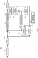
- FIG. 1 illustrates an exemplary video encoder 100, such as a High Efficiency Video Coding (HEVC) encoder.
- FIG. 1 may also illustrate an encoder in which improvements are made to the HEVC standard or an encoder employing technologies similar to HEVC, such as a JEM (Joint Exploration Model) encoder under development by JVET (Joint Video Exploration Team).
- JEM Joint Exploration Model
- JVET Joint Video Exploration Team
- the terms “reconstructed” and “decoded” may be used interchangeably, the terms “encoded” or “coded” may be used interchangeably, and the terms “image,” “picture” and “frame” may be used interchangeably.
- the term “reconstructed” is used at the encoder side while “decoded” is used at the decoder side.
- the video sequence may go through pre-encoding processing (101), for example, applying a color transform to the input color picture (e.g., conversion from RGB 4:4:4 to YCbCr 4:2:0), or performing a remapping of the input picture components in order to get a signal distribution more resilient to compression (for instance using a histogram equalization of one of the color components).
- Metadata can be associated with the preprocessing, and attached to the bitstream.
- a picture is partitioned (102) into one or more slices where each slice can include one or more slice segments.
- a slice segment is organized into coding units, prediction units, and transform units.
- the HEVC specification distinguishes between “blocks” and “units,” where a "block” addresses a specific area in a sample array (e.g., luma, Y), and the "unit” includes the collocated blocks of all encoded color components (Y, Cb, Cr, or monochrome), syntax elements, and prediction data that are associated with the blocks (e.g., motion vectors).
- a picture is partitioned into coding tree blocks (CTB) of square shape with a configurable size, and a consecutive set of coding tree blocks is grouped into a slice.
- a Coding Tree Unit (CTU) contains the CTBs of the encoded color components.
- a CTB is the root of a quadtree partitioning into Coding Blocks (CB), and a Coding Block may be partitioned into one or more Prediction Blocks (PB) and forms the root of a quadtree partitioning into Transform Blocks (TBs).
- CB Coding Tree Unit
- PB Prediction Blocks
- TBs Transform Blocks
- a Coding Unit includes the Prediction Units (PUs) and the tree-structured set of Transform Units (TUs), a PU includes the prediction information for all color components, and a TU includes residual coding syntax structure for each color component.
- the size of a CB, PB, and TB of the luma component applies to the corresponding CU, PU, and TU.
- the term "block” can be used to refer, for example, to any of CTU, CU, PU, TU, CB, PB, and TB.
- the "block” can also be used to refer to a macroblock and a partition as specified in H.264/AVC or other video coding standards, and more generally to refer to an array of data of various sizes.
- a picture is encoded by the encoder elements as described below.
- the picture to be encoded is processed in units of CUs.
- Each CU is encoded using either an intra or inter mode.
- intra prediction 160
- inter mode motion estimation (175) and compensation (170) are performed.
- the encoder decides (105) which one of the intra mode or inter mode to use for encoding the CU, and indicates the intra/inter decision by a prediction mode flag. Prediction residuals are calculated by subtracting (110) the predicted block from the original image block.
- CUs in intra mode are predicted from reconstructed neighboring samples (i.e., reference samples) within the same slice.
- the causal neighboring CUs have already been encoded/decoded when the encoding/decoding of the current CU is considered.
- the encoder and the decoder have the same prediction. Therefore, both the encoder and the decoder use the information from the reconstructed/decoded neighboring causal CUs to form prediction for the current CU.
- the intra prediction process in HEVC includes three steps: (1) reference sample generation, (2) intra sample prediction, and (3) post-processing (also called “post-filtering” or “boundary filtering") of predicted samples.
- Exemplary HEVC reference samples are illustrated in FIG. 3 , where the reference sample value at coordinate (x, y), with respect to the above-left corner of the current block, is indicated by R(x,y), and the predicted sample value at coordinate (x, y) of the current block is indicated by P(x,y).
- R(x,y) the reference sample value at coordinate (x, y)
- P(x,y) the predicted sample value at coordinate (x, y) of the current block
- a row of 2N decoded samples on the top is formed from the decoded CUs.
- a column of 2N samples on the left is formed from the decoded CUs.
- the corner sample from the above-left decoded CU is used to fill up the gap between the above row and the left column references. If some of the samples are not available, for example, when the corresponding CUs are not in the same slice or the current CU is at a frame boundary, then reference sample substitution is performed where the missing samples are copied from the available samples in a clock-wise direction. Then, depending on the current CU size and the prediction mode, the reference samples are filtered using a specified filter.
- the next step i.e., the intra sample prediction, consists of predicting the samples of the target CU based on the reference samples.
- HEVC supports a range of prediction methods.
- planar and DC prediction modes are used to predict smooth and gradually changing regions
- directional prediction modes also referred to as “angular prediction modes”
- angular prediction modes are used to capture different directional structures.
- HEVC supports 33 directional prediction modes which are indexed from 2 to 34. These prediction modes correspond to different prediction directions as illustrated in FIG. 4A , wherein the numbers (i.e., 2, 3, ..., 34) denote intra prediction mode indices.
- the prediction modes 2-17 are denoted as horizontal prediction modes (H-26 to H+32), as the predominant sources of prediction is in horizontal direction.
- the modes 18-34 are denoted as vertical prediction modes (V-32 to V+32) accordingly.
- “H” and "V” in FIG. 4A are used to indicate the horizontal and vertical directionalities, respectively, while the numeric part of the identifier indicates the samples' displacement (also referred to as "angle parameter") at 1/32 sample fractions.
- the directions with non-negative displacements are also denoted as positive directions, and the directions with negative displacements (i.e., H-2 to H-26 and V-2 to V-32) are also denoted as negative directions.
- a reference array is first constructed using the top and left reference samples. For vertical predictions, the reference array is horizontal (i.e., a reference row) and for horizontal predictions, the reference array is vertical (i.e., a reference column). For the modes with negative directions, the reference array needs samples from both the top and left reference arrays.
- the prediction at any sample position ( x , y ) inside the target PU is obtained by projecting the sample position to the reference array along the selected direction and interpolating a value for the sample at 1/32 sample accuracy.
- the predicted sample value is computed by interpolating between two closest reference samples.
- the interpolated sample is also called the predictor sample.
- prediction modes such as the DC mode and directly horizontal (i.e., mode 10) and directly vertical modes (i.e., mode 26) may cause discontinuity at the CU boundaries of the prediction samples. Therefore, such prediction modes are followed by a post-processing step where the boundary of the predicted samples are smoothed using a low-pass filter or a gradient-based update.
- directly horizontal mode refers to the prediction mode when the reference samples on the left side of a target block are repeated horizontally to the right for intra prediction.
- directly vertical mode refers to the prediction mode when the reference samples on the top of a target block are repeated vertically down for intra prediction.
- the low-pass filter is applied in DC prediction mode whereas the gradient-based update is applied in directly horizontal and directly vertical modes.
- both the top and the left boundary of the target block are filtered as follows.
- the decoder needs the mode information to form the prediction for an intra-coded CU.
- the encoder encodes the mode information using a most probable mode (MPM) set for the luma component.
- MPM most probable mode
- HEVC specifies an MPM set consisting of three distinct modes, which is constructed from the prediction modes of the intra coded CUs on the top and left of the current CU, the planar mode, the DC mode, and the directly vertical mode.
- the applicable luma intra prediction mode for the current block can be coded using two different options. If the applicable mode is included in a constructed list of three most probable modes (MPM), the mode is signaled by an index in the MPM list. Otherwise, the mode is signaled by a fixed-length binarization of the mode index.
- the three most probable modes are derived from the intra prediction modes of the top and left neighboring blocks.
- the corresponding coding block is further partitioned into one or more prediction blocks. Inter prediction is performed on the PB level, and the corresponding PU contains the information about how inter prediction is performed.
- the motion information e.g., motion vector and reference picture index
- AMVP advanced motion vector prediction
- a video encoder or decoder In the merge mode, a video encoder or decoder assembles a candidate list based on already coded blocks, and the video encoder signals an index for one of the candidates in the candidate list.
- the motion vector (MV) and the reference picture index are reconstructed based on the signaled candidate.
- AMVP a video encoder or decoder assembles candidate lists based on motion vectors determined from already coded blocks.
- the video encoder then signals an index in the candidate list to identify a motion vector predictor (MVP) and signals a motion vector difference (MVD).
- MVP motion vector predictor
- MVD motion vector difference
- the motion vector (MV) is reconstructed as MVP+MVD.
- the applicable reference picture index is also explicitly coded in the PU syntax for AMVP.
- the prediction residuals are then transformed (125) and quantized (130).
- the quantized transform coefficients, as well as motion vectors and other syntax elements, are entropy coded
- the encoder may also skip the transform and apply quantization directly to the non-transformed residual signal on a 4x4 TU basis.
- the encoder may also bypass both transform and quantization, i.e., the residual is coded directly without the application of the transform or quantization process.
- direct PCM coding no prediction is applied and the coding unit samples are directly coded into the bitstream.
- the encoder decodes an encoded block to provide a reference for further predictions.
- the quantized transform coefficients are de-quantized (140) and inverse transformed (150) to decode prediction residuals.
- In-loop filters (165) are applied to the reconstructed picture, for example, to perform deblocking/SAO (Sample Adaptive Offset) filtering to reduce encoding artifacts.
- the filtered image is stored at a reference picture buffer (180).
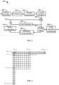
- FIG. 2 illustrates a block diagram of an exemplary video decoder 200, such as an HEVC decoder.
- a bitstream is decoded by the decoder elements as described below.
- Video decoder 200 generally performs a decoding pass reciprocal to the encoding pass as described in FIG. 1 , which performs video decoding as part of encoding video data.
- FIG. 2 may also illustrate a decoder in which improvements are made to the HEVC standard or a decoder employing technologies similar to HEVC, such as a JEM decoder.
- the input of the decoder includes a video bitstream, which may be generated by video encoder 100.
- the bitstream is first entropy decoded (230) to obtain transform coefficients, motion vectors, picture partitioning information, and other coded information.
- the picture partitioning information indicates the size of the CTUs, and a manner a CTU is split into CUs, and possibly into PUs when applicable.
- the decoder may therefore divide (235) the picture into CTUs, and each CTU into CUs, according to the decoded picture partitioning information.
- the transform coefficients are de-quantized (240) and inverse transformed (250) to decode the prediction residuals.
- an image block is reconstructed.
- the predicted block may be obtained (270) from intra prediction (260) or motion-compensated prediction (i.e., inter prediction) (275).
- AMVP and merge mode techniques may be used to derive motion vectors for motion compensation, which may use interpolation filters to calculate interpolated values for sub-integer samples of a reference block.
- In-loop filters (265) are applied to the reconstructed image.
- the filtered image is stored at a reference picture buffer (280).
- the decoded picture can further go through post-decoding processing (285), for example, an inverse color transform (e.g., conversion from YCbCr 4:2:0 to RGB 4:4:4) or an inverse remapping performing the inverse of the remapping process performed in the pre-encoding processing (101).
- post-decoding processing may use metadata derived in the pre-encoding processing and signaled in the bitstream.
- encoding of a frame of a video sequence is based on a block structure.
- a frame is divided into square coding tree units (CTUs), which may undergo quadtree (QT) splitting to multiple coding units based on rate-distortion criteria.
- CTUs square coding tree units
- QT quadtree
- Each CU is either intra-predicted, that is spatially predicted from the causal neighbor CUs, or inter-predicted, that is, temporally predicted from reference frames already decoded.
- I-slices all CUs are intra-predicted, whereas in P and B slices the CUs can be either intra or inter-predicted.
- HEVC defines 35 prediction modes which include one planar mode (indexed as mode 0), one DC mode (indexed as mode 1) and 33 directional prediction modes (indexed as modes 2 - 34).
- the QTBT Quadtree plus Binary Tree
- a Coding Tree Unit (CTU) is firstly partitioned by a quadtree structure.
- the quadtree leaf nodes are further partitioned by a binary tree structure.
- the binary tree leaf node is named as Coding Units (CUs), which is used for prediction and transform without further partitioning.
- CUs Coding Units
- a CU consists of Coding Blocks (CBs) of different color components.
- JEM 3.0 uses 65 directional intra prediction modes in addition to the planar and DC modes, as shown in FIG. 4B .
- the modes are numbered from 2 to 66 in the increasing order, in the same fashion as done in HEVC from 2 to 34.
- the 65 directional prediction modes include the 33 directional prediction modes specified in HEVC plus 32 additional directional prediction modes that correspond to angles in-between two original angles. In other words, the prediction direction in JEM has twice the angle resolution of HEVC.
- the higher number of prediction modes has been proposed to exploit the possibility of angular structures with proposed larger block sizes. Corresponding to the higher number of modes, there is a higher number of angle parameter A values.
- mode 18 is the directly horizontal mode
- mode 50 is the directly vertical mode
- modes 2-17 and 51-66 have positive directions
- modes 19-49 have negative directions.
- Modes 2 and 66 are strictly diagonal modes (i.e., at ⁇ 45 degree), and a mode (e.g., modes 3-10 and 58-65) can be considered as a diagonal mode if the difference between the mode and the strictly diagonal mode (e.g., mode 2, 66) is smaller than a threshold (e.g., 8).
- a threshold e.g. 8
- JEM can also have rectangular CUs because of the QTBT structure.
- the reference arrays on the top and on the left have length 1+W+H samples.
- higher order filters have been proposed (4-tap cubic and Gaussian filters) for different block sizes.
- a boundary filters for intra prediction modes 2 and 3-10 are similar. Using the reference samples on the top, the target samples in the rows 1-4 are filtered in mode 2, and the samples in row 1 are filtered in modes 3-10. This post-filtering is applied to luma blocks only.
- JCTVC-G280 also applies the concept to the two positive directions closest to the vertical or horizontal direction. Considering the 35 modes in HEVC, these directions will be associated with modes 8 and 9 (mode 10 is the horizontal direction), and modes 27 and 28 (mode 26 is the vertical direction).
- the predictor is interpolated if it does not coincide with any reference sample on the top reference array.
- the predictor is interpolated if it does not coincide with any reference sample on the left reference array.
- Multi-reference intra prediction refers to intra prediction using multiple rows and columns of reference samples.
- a reference layer as a combination of reference arrays (one on the top and one on the left) at a certain distance from the target block and corner samples. That is, by a reference layer, we refer to both the top and the left reference arrays.
- the existing reference arrays in HEVC or JEM
- the decoded samples right above the top reference array and to left of the left reference array they will constitute the second reference layer, and so on, as shown in FIG. 6 .
- the reference layer is referred to as a reference tier or reference line.
- reference layer n consists of (W+H+n-1) decoded row samples on the top, (W+H+n-1) decoded column samples on the left, and (2*n-1) top-left corner samples.
- Multi-reference intra prediction is also called arbitrary tier reference intra prediction (as described in " Arbitrary reference tier for intra directional modes," Y.-J. Chang, P.-H. Lin, C.-L. Lin, J.-S. Tu, and C.-C. Lin, JVET-C0043, Geneva, CH, May 2016 or " Arbitrary Reference Tier for Intra Directional Modes, with Supplementary Results," Y.-J. Chang, P.-H. Lin, C.-L. Lin, C.-C. Lin, JVET-D0099, Chengdu, CN, October 2016 .) or multi-line intra prediction (as described in " Multiple line-based intra prediction," J. Li, B. Li, J. Xu, R. Xiong, and G. J. Sullivan, JVET-C0071, Geneva, CH, May 2016 ).
- a target block is predicted using each reference layer.
- the reference layer producing the best RD (Rate-Distortion) performance is signaled to the decoder so that the decoder uses the same reference layer as the encoder.
- the prediction with any reference layer can be made in the same manner as done in HEVC, or predictions made from the reference layers farther from the target block can be improved by compensating by the residues for the reference layers closer to the target block.
- Pn represents the prediction based on the n-th reference layer
- w1, w2, ..., wn are weights known to both the encoder and the decoder.
- the post-filtering still uses the reference samples on the first reference layer since it is adjacent to the target block boundaries on the top and on the left.
- the present embodiments can be applied to any number of reference layers.
- the computational complexity increases, and the efficacy of boundary filtering will be less pronounced as the reference layers will be farther away from the target block boundary.
- only two reference layers are used.
- P'(0,y) Clip(P(0,y) + (w1*((R(-1,y) - R(-1,-1)) >> 2) + w2*((R(-2,y) - R(-2,-2)) >> 2)) / (w1+w2)), 0 ⁇ y ⁇ H, where w1 and w2 denote the weights assigned to the 1st and 2nd reference layers.
- P'(x,0) Clip(P(x,0) + (w1*((R(x,-1) - R(-1,-1)) >> 2) + w2*((R(x,-2) - R(-2,-2)) >> 2)) / (w1+w2)), 0 ⁇ x ⁇ W.
- angular prediction modes for example, modes 2 to 10 and 58 to 66, we propose both a gradient approach and a low-pass filtering as described in the following.
- P ′ x y Clip P x y + ⁇ y * L x , 0 ⁇ x ⁇ W , where L(x) is a decay function having values in the closed interval [0, 1].
- P ' x y Clip P x y + ⁇ y * L x + k * Lmax / 2 / k * Lmax , 0 ⁇ x ⁇ W , where L(x) can have positive integral values, Lmax is the maximum value of L(x), and k is a tuning factor having value greater than 1.
- the above formulation will assign larger weights (i.e., L(x)) to the samples closer to the left boundary of the block.
- L(x) weights
- L(x) 64 >> (x ⁇ 2)
- L(x) 32 >> ((1+x) ⁇ 1)
- L(x) 32 >> (1 ⁇ (x >> 1)).
- the slope at the second reference layer i.e., at R(-2, y) or R(x,-2)
- the slopes at the two references can be compared and used as a condition to decide if the above filtering should be applied to the target block, or a low-pass filtering should be applied, which is presented in the following.
- the filtering is applied in the context of intra prediction with multiple reference layers. It should be noted that the gradient approach can also be applied to a target block even if the usage of multiple reference layers is disabled. In this case, instead of a weighted average, the predictions for the reference samples will be computed using samples from one reference layer only (but on the opposite side of the target block).
- JCTVC-G280 we use a similar formulation as JCTVC-G280 for computing the gradient but with different shift parameters to calculate the update term for the predicted samples.
- the shift parameters are selected so as to result in a dyadic decay of the gradient values away from the block boundary, and they are similar to the shift parameters given in an article entitled " Simplification and Extension of PDPC," X. Zhao, V. Seregin, A. Said, and M. Karczewicz, JVET-H0057, Macao, Oct 2017 (hereinafter "JVET-H0057 ").
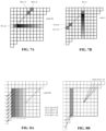
- the predictor sample value is computed in the same manner as in JEM, as shown in an example in FIG. 11A for mode 66. If the predictor sample's location coincides with a reference sample location, that reference sample is used as the predictor; otherwise an interpolated value is used as the predictor. In JEM, the interpolation can be performed with 4-Tap cubic or Gaussian filters.
- P ′ x y Clip P x y + ⁇ y * L x , 0 ⁇ x ⁇ W ;
- L(x) is a decay function having values in the closed interval [0, 1], and the clipping function has the range equal to the dynamic range of the sample value.
- P ′ x y Clip P x y + ⁇ y * L x + k * Lmax / 2 / k * Lmax , 0 ⁇ x ⁇ W ;
- L(x) can have positive integral values
- Lmax is the maximum value of L(x)
- k is a tuning factor having value greater than or equal to 1.
- the decay function can be different for different prediction modes, here we use the same decay function for all the above modes.
- the predictor for all reference samples R(-1,y), 0 ⁇ y ⁇ H is the top-left reference sample, which is R(-1,-1).
- any prediction mode in the range 2 -18 are associated with positive horizontal angular directions. The directions span from 45 degree to 0 degree in clockwise direction.
- the reference samples on the top of the target block i.e., R(x,-1), 0 ⁇ x ⁇ W
- R_x denote the predictor for the reference sample R(x,-1).
- ⁇ x R x , ⁇ 1 ⁇ R _ x .
- the predictor sample value can be computed in the same manner as in JEM, as shown in an example in FIG. 11B for mode 2.
- P ′ x y Clip P x y + ⁇ x * L y , 0 ⁇ y ⁇ H , where L(y) is a decay function.
- L(y) is a decay function.
- P ′ x y Clip P x y + ⁇ x * L y + 32 ⁇ 6 , 0 ⁇ y ⁇ H
- the predictor for all reference samples R(x,-1), 0 ⁇ x ⁇ W is the top-left reference sample R(-1,-1).
- P(x,y) R(x,-1).
- P ′ x 0 16 * P x 0 + 12 * R x + 1 , ⁇ 1 + 4 * R x + 2 , ⁇ 2 + 16 ⁇ 5 ;
- P ′ x 1 20 * P x 1 + 9 * R x + 2 , ⁇ 1 + 3 * R x + 3 , ⁇ 2 + 16 ⁇ 5 ;
- P ′ x 2 24 * P x 2 + 6 * R x + 3 , ⁇ 1 + 2 * R x + 4 , ⁇ 2 + 16 ⁇ 5 ;
- P ′ x 3 28 * P x 3 + 3 * R x + 4 , ⁇ 1 + R x + 5 , ⁇ 2 + 16 ⁇ 5 ;
- the filtering is done in an analogous manner. Using the reference samples on the top two reference layers, the target samples in row 1 are filtered using the same filtered coefficients and offsets.
- low-pass filtering is described with respect to different modes, namely, different filters are used for different (sets of) modes.
- filters and the mapping between filters and modes are just for exemplary purposes, and the present embodiments can be applied to other filters and other mappings between the filters and modes.
- FIG. 9 illustrates an exemplary method 900 for performing gradient-based post-filtering in intra prediction, according to an embodiment.
- the reference layers are constructed (910), for example, as shown in FIG. 6 , by using the already decoded samples in the top, top-right, left, left-bottom, and top-left CUs and then filtered. Then, for a given prediction mode, we predict (920, 930) the target block, first using the first reference layer, then using the second reference layer, and then compute (940) the prediction as a weighted average of the two.
- the filtering method can use gradient computed (950) at either one reference layer, or at two reference layers and then taking a weighted average of the two. This embodiment also includes the case when only one reference layer is used for generating the prediction (i.e., steps 930 and 940 are omitted) by deactivating the multi-reference usage parameter.
- the predictions at row y are then adjusted (960) by post-filtering, for example, according to Eq. (1).
- the intra prediction for the target block is completed.
- the prediction residuals for the block can then be calculated based on the original block and the predicted block, and the residual block is encoded as well as the selected intra prediction mode.
- the block can be decoded as a sum of the predicted block and the residual block.
- FIG. 10 illustrates an exemplary method 1000 for adaptively choosing the boundary filtering method for intra prediction, according to an embodiment, Method 1000 can be used at both the encoder and decoder.
- Method 1000 starts at initialization step 1005.
- the encoder or decoder may access the intra prediction mode for the current block, and decide whether the current block is a luma or chroma block. If the current block is not a luma block (1010), then the encoder or decoder performs (1015) multi-reference intra prediction for the chroma block and the intra prediction is completed.
- the encoder or decoder performs (1020) multi-reference intra prediction for the luma block. Then based on the intra direction mode, the boundary filtering method is adaptively selected.
- the encoder or decoder may choose (1035) the JEM boundary filtering method.
- the mode is a mode very close to the directly horizontal mode (1040), i.e., the difference of the mode indices between the current mode and the directly horizontal mode is smaller than a threshold (e.g., mode 16, 17, 19, 20)
- a threshold e.g., mode 16, 17, 19, 20
- the encoder or decoder may choose (1055) the vertical boundary filtering method. Steps 1040 and 1050 may further consider the block size and the encoder or decoder only chooses horizontal or vertical filtering when the block size is smaller than 32x32. Otherwise, if (1060) the mode is diagonal and in positive directions (e.g., between modes 2-10 and 58-66), the encoder or decoder may choose (1065) the gradient-based filtering method, for example, using method 900. If the mode does not satisfy any of the above conditions, then the encoder or decoder does not perform any post-processing and the prediction is completed.
- a threshold e.g., mode 48, 49, 51, 52
- the filtering is typically only applied for an intra prediction mode with a positive direction including both directly vertical and directly horizontal modes, and only one or two negative directions close to the directly vertical and directly horizontal modes.
- the top boundary is filtered, that is, the samples in the target block that are close to the top boundary (i.e., samples with a sample distance to the top boundary smaller than a threshold) are adjusted; and for the vertical modes, the left boundary is filtered. Exactly how many samples are filtered may be based on the filtering method and the intra prediction mode.
- the gradient-based approach is used for some directions considering a trade-off between the compression efficiency gain and computational complexity increase. It should be noted that it is not mandatory to restrict the application of the gradient-based approach only to the modes as described above. Rather, it can be applied to all positive prediction directions. Furthermore, the present embodiments can still be applied when the number of intra prediction modes go beyond 67, which is supported by JEM codec (for example, the future H266 standard may support more than 67 intra prediction modes). In that case, the proposed gradient-based filtering can still be applied to some or all positive prediction directions. For example, the gradient-based filtering can be applied to diagonal modes in positive directions.
- Method 1000 may be modified.
- step 1065 may be replaced by low-pass filtering as described before.
- the gradient-based method can be used followed by the low-pass filtering. If the usage of multiple reference layers is deactivated, then we compute gradient with one reference layer, which we use in gradient-based filtering, and then use the existing boundary filters in JEM.
- This embodiment also includes the combined cases where we can apply the gradient-based method to certain eligible modes and the low-pass filtering to some other modes, and both to some eligible modes.
- the decision to apply either of the two filtering methods can be decided adaptively or be based on a pre-determined rule. As an example, we can apply the low-pass filtering to mode 2 and mode 66 always.
- the encoder / decoder prediction process is the same as method 1000 except that the gradient-based filtering (1065) is replaced by combined gradient and low-pass boundary filtering.
- the methods as described above can be applied at different levels, for example, at a slice level, a picture level, or a sequence level, and the usage of a proposed method can be signalled in the bitstream.
- a proposed method can be signalled in the bitstream.
- PPS Picture Parameter Set
- SPS Sequence Parameter Set
- Table 2 shows the BD-rate (Bjentegaard Delta-Rate) performance of the proposed multi-reference boundary filtering versus the existing single-reference boundary filtering with multi-reference intra prediction.
- Table 2 shows the BD-rate gain of 0.14% on the average for the luma component.
- each of the methods comprises one or more steps or actions for achieving the described method. Unless a specific order of steps or actions is required for proper operation of the method, the order and/or use of specific steps and/or actions may be modified or combined.
- numeric values are used in the present application, for example, the values of the weights, the block size, filter length, filter coefficients, or the specific modes corresponding to a filtering method. It should be noted that the specific values are for exemplary purposes and the present embodiments are not limited to these specific values.
- boundary filtering can be used to modify the intra prediction module (160, 260) of the JVET or HEVC encoder and decoder as shown in FIG. 1 and FIG. 2 .
- present embodiments are not limited to JVET or HEVC, and can be applied to other standards, recommendations, and extensions thereof.
- Various embodiments described above can be used individually or in combination.
- FIG. 13 illustrates a block diagram of an example of a system in which various aspects and embodiments are implemented.
- System 1300 can be embodied as a device including the various components described below and is configured to perform one or more of the aspects described in this application. Examples of such devices, include, but are not limited to, various electronic devices such as personal computers, laptop computers, smartphones, tablet computers, digital multimedia set top boxes, digital television receivers, personal video recording systems, connected home appliances, and servers.
- Elements of system 1300, singly or in combination can be embodied in a single integrated circuit, multiple ICs, and/or discrete components.
- the processing and encoder/decoder elements of system 1300 are distributed across multiple ICs and/or discrete components.
- system 1300 is communicatively coupled to other systems, or to other electronic devices, via, for example, a communications bus or through dedicated input and/or output ports.
- system 1300 is configured to implement one or more of the aspects described in this document.
- the system 1300 includes at least one processor 1310 configured to execute instructions loaded therein for implementing, for example, the various aspects described in this document.
- Processor 1310 can include embedded memory, input output interface, and various other circuitries as known in the art.
- the system 1300 includes at least one memory 1320 (e.g., a volatile memory device, and/or a non-volatile memory device).
- System 1300 includes a storage device 1340, which can include non-volatile memory and/or volatile memory, including, but not limited to, EEPROM, ROM, PROM, RAM, DRAM, SRAM, flash, magnetic disk drive, and/or optical disk drive.
- the storage device 1340 can include an internal storage device, an attached storage device, and/or a network accessible storage device, as non-limiting examples.
- System 1300 includes an encoder/decoder module 1330 configured, for example, to process data to provide an encoded video or decoded video, and the encoder/decoder module 1330 can include its own processor and memory.
- the encoder/decoder module 1330 represents module(s) that can be included in a device to perform the encoding and/or decoding functions. As is known, a device can include one or both of the encoding and decoding modules. Additionally, encoder/decoder module 1330 can be implemented as a separate element of system 1300 or can be incorporated within processor 1310 as a combination of hardware and software as known to those skilled in the art.
- processor 1310 Program code to be loaded onto processor 1310 or encoder/decoder 1330 to perform the various aspects described in this document can be stored in storage device 1340 and subsequently loaded onto memory 1320 for execution by processor 1310.
- processor 1310, memory 1320, storage device 1340, and encoder/decoder module 1330 can store one or more of various items during the performance of the processes described in this document.
- Such stored items can include, but are not limited to, the input video, the decoded video or portions of the decoded video, the bitstream, matrices, variables, and intermediate or final results from the processing of equations, formulas, operations, and operational logic.
- memory inside of the processor 1310 and/or the encoder/decoder module 1330 is used to store instructions and to provide working memory for processing that is needed during encoding or decoding.
- a memory external to the processing device (for example, the processing device can be either the processor 1310 or the encoder/decoder module 1330) is used for one or more of these functions.
- the external memory can be the memory 1320 and/or the storage device 1340, for example, a dynamic volatile memory and/or a non-volatile flash memory.
- an external non-volatile flash memory is used to store the operating system of a television.
- a fast external dynamic volatile memory such as a RAM is used as working memory for video coding and decoding operations, such as for MPEG-2, HEVC, or VVC (Versatile Video Coding).
- the input to the elements of system 1300 can be provided through various input devices as indicated in block 1305.
- Such input devices include, but are not limited to, (i) an RF portion that receives an RF signal transmitted, for example, over the air by a broadcaster, (ii) a Composite input terminal, (iii) a USB input terminal, and/or (iv) an HDMI input terminal.
- the input devices of block 1305 have associated respective input processing elements as known in the art.
- the RF portion can be associated with elements suitable for (i) selecting a desired frequency (also referred to as selecting a signal, or band-limiting a signal to a band of frequencies), (ii) downconverting the selected signal, (iii) band-limiting again to a narrower band of frequencies to select (for example) a signal frequency band which can be referred to as a channel in certain embodiments, (iv) demodulating the downconverted and band-limited signal, (v) performing error correction, and (vi) demultiplexing to select the desired stream of data packets.
- the RF portion of various embodiments includes one or more elements to perform these functions, for example, frequency selectors, signal selectors, band-limiters, channel selectors, filters, downconverters, demodulators, error correctors, and demultiplexers.
- the RF portion can include a tuner that performs various of these functions, including, for example, downconverting the received signal to a lower frequency (for example, an intermediate frequency or a near-baseband frequency) or to baseband.
- the RF portion and its associated input processing element receives an RF signal transmitted over a wired (for example, cable) medium, and performs frequency selection by filtering, downconverting, and filtering again to a desired frequency band.
- Adding elements can include inserting elements in between existing elements, for example, inserting amplifiers and an analog-to-digital converter.
- the RF portion includes an antenna.
- USB and/or HDMI terminals can include respective interface processors for connecting system 1300 to other electronic devices across USB and/or HDMI connections.
- various aspects of input processing for example, Reed-Solomon error correction, can be implemented, for example, within a separate input processing IC or within processor 1310 as necessary.
- aspects of USB or HDMI interface processing can be implemented within separate interface ICs or within processor 1310 as necessary.
- the demodulated, error corrected, and demultiplexed stream is provided to various processing elements, including, for example, processor 1310, and encoder/decoder 1330 operating in combination with the memory and storage elements to process the datastream as necessary for presentation on an output device.
- connection arrangement 1315 for example, an internal bus as known in the art, including the 12C bus, wiring, and printed circuit boards.
- the system 1300 includes communication interface 1350 that enables communication with other devices via communication channel 1390.
- the communication interface 1350 can include, but is not limited to, a transceiver configured to transmit and to receive data over communication channel 1390.
- the communication interface 1350 can include, but is not limited to, a modem or network card and the communication channel 1390 can be implemented, for example, within a wired and/or a wireless medium.
- Data is streamed to the system 1300, in various embodiments, using a Wi-Fi network such as IEEE 802.11.
- the Wi-Fi signal of these embodiments is received over the communications channel 1390 and the communications interface 1350 which are adapted for Wi-Fi communications.
- the communications channel 1390 of these embodiments is typically connected to an access point or router that provides access to outside networks including the Internet for allowing streaming applications and other over-the-top communications.
- Other embodiments provide streamed data to the system 1300 using a set-top box that delivers the data over the HDMI connection of the input block 1305.
- Still other embodiments provide streamed data to the system 1300 using the RF connection of the input block 1305.
- the system 1300 can provide an output signal to various output devices, including a display 1365, speakers 1375, and other peripheral devices 1385.
- the other peripheral devices 1385 include, in various examples of embodiments, one or more of a stand-alone DVR, a disk player, a stereo system, a lighting system, and other devices that provide a function based on the output of the system 1300.
- control signals are communicated between the system 1300 and the display 1365, speakers 1375, or other peripheral devices 1385 using signaling such as AV.Link, CEC, or other communications protocols that enable device-to-device control with or without user intervention.
- the output devices can be communicatively coupled to system 1300 via dedicated connections through respective interfaces 1360, 1370, and 1380.
- the output devices can be connected to system 1300 using the communications channel 1390 via the communications interface 1350.
- the display 1365 and speakers 1375 can be integrated in a single unit with the other components of system 1300 in an electronic device, for example, a television.
- the display interface 1360 includes a display driver, for example, a timing controller (T Con) chip.
- the display 1365 and speaker 1375 can alternatively be separate from one or more of the other components, for example, if the RF portion of input 1305 is part of a separate set-top box.
- the output signal can be provided via dedicated output connections, including, for example, HDMI ports, USB ports, or COMP outputs.
- a method for video decoding comprising: accessing a predicted value of a sample of a block of an image in a video, corresponding to an intra prediction mode; determining, based on a location of said sample in said block and said intra prediction mode, that said predicted value of said sample is to be adjusted; adjusting said predicted value of said sample, responsive to a reference sample and a predicted value of said reference sample; accessing prediction residual of said sample; and decoding said sample responsive to said adjusted predicted value and said prediction residual.
- a method for video encoding comprising: accessing a predicted value of a sample of a block of an image in a video, corresponding to an intra prediction mode; determining, based on a location of said sample in said block and said intra prediction mode, that said predicted value of said sample is to be adjusted; adjusting predicted value of said sample, responsive to reference sample and a predicted value of said reference sample; generating prediction residual for said sample responsive to said adjusted predicted value; and encoding said intra prediction mode and said prediction residual.
- an apparatus for video decoding comprising one or more processors, wherein said one or more processors are configured to: access a predicted value of a sample of a block of an image in a video, corresponding to an intra prediction mode; determine, based on a location of said sample in said block and said intra prediction mode, that said predicted value of said sample is to be adjusted; adjust said predicted value of said sample, responsive to a reference sample and a predicted value of said reference sample; access prediction residual of said sample; and decode said sample responsive to said adjusted predicted value and said prediction residual.
- an apparatus for video encoding comprising one or more processors, wherein said one or more processors are configured to: access a predicted value of a sample of a block of an image in a video, corresponding to an intra prediction mode; determine, based on a location of said sample in said block and said intra prediction mode, that said predicted value of said sample is to be adjusted; adjust said predicted value of said sample, responsive to a reference sample and a predicted value of said reference sample; generate prediction residual for said sample responsive to said adjusted predicted value; and encode said intra prediction mode and said prediction residual.
- an apparatus for video decoding comprising: means for accessing a predicted value of a sample of a block of an image in a video, corresponding to an intra prediction mode; means for determining, based on a location of said sample in said block and said intra prediction mode, that said predicted value of said sample is to be adjusted; means for adjusting said predicted value of said sample, responsive to a reference sample and a predicted value of said reference sample; means for accessing prediction residual of said sample; and means for decoding said sample responsive to said adjusted predicted value and said prediction residual.
- an apparatus for video encoding comprising: means for accessing a predicted value of a sample of a block of an image in a video, corresponding to an intra prediction mode; means for determining, based on a location of said sample in said block and said intra prediction mode, that said predicted value of said sample is to be adjusted; means for adjusting said predicted value of said sample, responsive to a reference sample and a predicted value of said reference sample; means for generating prediction residual for said sample responsive to said adjusted predicted value; and means for encoding said intra prediction mode and said prediction residual.
- a video signal formed by performing: accessing a predicted value of a sample of a block of an image in a video, corresponding to an intra prediction mode; determining, based on a location of said sample in said block and said intra prediction mode, that said predicted value of said sample is to be adjusted; adjusting predicted value of said sample, responsive to reference sample and a predicted value of said reference sample; generating prediction residual for said sample responsive to said adjusted predicted value; and encoding said intra prediction mode and said prediction residual.
- said adjusting is based on a gradient between a reference sample and said predicted value of said reference sample.
- said predicted value for said reference sample is responsive to said intra prediction mode.
- said reference sample is at a same row or column as said sample of said block.
- said adjusting is responsive to said gradient and a weight, said weight being based on a location of said sample of said block.
- said sample is determined to be adjusted when said sample is close to a left boundary and said intra prediction mode corresponds to a vertical prediction direction.
- said sample is determined to be adjusted when said sample is close to a top boundary and said intra prediction mode corresponds to a horizontal prediction direction.
- said adjustment is performed by choosing, responsive to said intra prediction mode, a filtering method to adjust said predicted value.
- whether to adjust is based on an average of gradients at a reference array.
- said predicted value of said reference sample is a value of a top-left reference sample.
- An embodiment provides a computer program comprising instructions which when executed by one or more processors cause the one or more processors to perform the encoding method or decoding method according to any of the embodiments described above.
- One or more of the present embodiments also provide a computer readable storage medium having stored thereon instructions for encoding or decoding video data according to the methods described above.
- One or more embodiments also provide a computer readable storage medium having stored thereon a bitstream generated according to the methods described above.
- One or more embodiments also provide a method and apparatus for transmitting or receiving the bitstream generated according to the methods described above.
- Decoding can encompass all or part of the processes performed, for example, on a received encoded sequence in order to produce a final output suitable for display.
- processes include one or more of the processes typically performed by a decoder, for example, entropy decoding, inverse quantization, inverse transformation, and differential decoding.
- a decoder for example, entropy decoding, inverse quantization, inverse transformation, and differential decoding.
- encoding can encompass all or part of the processes performed, for example, on an input video sequence in order to produce an encoded bitstream.
- the implementations described herein may be implemented in, for example, a method or a process, an apparatus, a software program, a data stream, or a signal. Even if only discussed in the context of a single form of implementation (for example, discussed only as a method), the implementation of features discussed may also be implemented in other forms (for example, an apparatus or a program).
- An apparatus may be implemented in, for example, appropriate hardware, software, and firmware.
- the methods may be implemented in, for example, an apparatus such as, for example, a processor, which refers to processing devices in general, including, for example, a computer, a microprocessor, an integrated circuit, or a programmable logic device. Processors also include communication devices, such as, for example, computers, cell phones, portable/personal digital assistants ("PDAs”), and other devices that facilitate communication of information between end-users.
- PDAs portable/personal digital assistants
- the appearances of the phrase “in one embodiment” or “in an embodiment” or “in one implementation” or “in an implementation”, as well any other variations, appearing in various places throughout the specification are not necessarily all referring to the same embodiment.
- Determining the information may include one or more of, for example, estimating the information, calculating the information, predicting the information, or retrieving the information from memory.
- Accessing the information may include one or more of, for example, receiving the information, retrieving the information (for example, from memory), storing the information, moving the information, copying the information, calculating the information, predicting the information, or estimating the information.
- Receiving is, as with “accessing”, intended to be a broad term.
- Receiving the information may include one or more of, for example, accessing the information, or retrieving the information (for example, from memory).
- “receiving” is typically involved, in one way or another, during operations such as, for example, storing the information, processing the information, transmitting the information, moving the information, copying the information, erasing the information, calculating the information, determining the information, predicting the information, or estimating the information.
- implementations may produce a variety of signals formatted to carry information that may be, for example, stored or transmitted.
- the information may include, for example, instructions for performing a method, or data produced by one of the described implementations.
- a signal may be formatted to carry the bitstream of a described embodiment.
- Such a signal may be formatted, for example, as an electromagnetic wave (for example, using a radio frequency portion of spectrum) or as a baseband signal.
- the formatting may include, for example, encoding a data stream and modulating a carrier with the encoded data stream.
- the information that the signal carries may be, for example, analog or digital information.
- the signal may be transmitted over a variety of different wired or wireless links, as is known.
- the signal may be stored on a processor-readable medium.
Landscapes
- Engineering & Computer Science (AREA)
- Multimedia (AREA)
- Signal Processing (AREA)
- Compression Or Coding Systems Of Tv Signals (AREA)
Claims (10)
- Verfahren zur Video-Dekodierung, umfassend:Bestimmen, nach einem Intra-Prädiktionsmodus, eines Vorhersagewertes P(x,y) eines Samples in Position (x,y) eines rechteckigen Blocks mit einer Breite W und einer Höhe H eines Bilds in einem Video,wobei im Fall eines vertikalen Prädiktionsmodus,Vorhersage eines Referenz-Samples R(-1,y), 0 ≤ y < H, links vom Block, aus einem Prädiktor (R_y), oberhalb des Blocks, durch den vertikalen Prädiktionsmodus,Bestimmen des Gradienten bei (-1, y), 0 ≤ y < H, als Δ(y) = R(-1,y) - R_y,Modifizieren der Sample-Vorhersagewerte des Blocks in Zeile y als P'(x,y) = Clip(P(x,y) + (Δ(y)* L(x)), 0 ≤ x < W, wobei L(x) eine Zerfallsfunktion ist, die Werte in dem geschlossenen Intervall [0,1] aufweist, und die Clipping-Funktion den Bereich aufweist, der gleich dem dynamischen Bereich des Sample-Wertes ist, undZuweisung größerer Gewichte L(x) an die Samples, die sich näher an der linken Grenze des Blocks befinden;wobei im Fall eines horizontalen Prädiktionsmodus,Vorhersage eines Referenz-Samples R(x,-1), 0 ≤ x < W, oberhalb des Blocks, aus einem Prädiktor (R_x), links vom Block, durch den horizontalen Prädiktionsmodus,Bestimmen des Gradienten bei (x,-1), 0 ≤ x < W, als Δ(x) = R(x,-1) - R_x;Modifizieren der Sample-Vorhersagewerte des Blocks in Zeile y als P'(x,y) = Clip(P(x,y) + Δ(x)* L(y)), 0 ≤ y < H, wobei L(y) eine Zerfallsfunktion ist, die Werte in dem geschlossenen Intervall [0,1] aufweist, und die Clipping-Funktion den Bereich aufweist, der gleich dem dynamischen Bereich des Sample-Wertes ist, undZuweisung größerer Gewichte L(x) an die Samples, die sich näher an der oberen Grenze des Blocks befinden;Bestimmen eines Prädiktionsrests des genannten Samples; undDekodieren des genannten Samples an Position (x,y), unter Verwendung des genannten angepassten Vorhersagewertes P'(x,y) und des genannten Prädiktionsrests.
- Verfahren zur Video-Kodierung, umfassend:Bestimmen, nach einem Intra-Prädiktionsmodus, eines Vorhersagewertes P(x,y) eines Samples in Position (x,y) eines rechteckigen Blocks mit einer Breite W und einer Höhe H eines Bilds in einem Video,wobei im Fall eines vertikalen Prädiktionsmodus,Vorhersage eines Referenz-Samples R(-1,y), 0 ≤ y < H, links vom Block, aus einem Prädiktor (R_y), oberhalb des Blocks, durch den vertikalen Prädiktionsmodus,Bestimmen des Gradienten bei (-1, y), 0 ≤ y < H, als Δ(y) = R(-1,y) - R_y,Modifizieren der Sample-Vorhersagewerte des Blocks in Zeile y als P'(x,y) = Clip(P(x,y) + (Δ(y)* L(x)), 0 ≤ x < W, wobei L(x) eine Zerfallsfunktion ist, die Werte in dem geschlossenen Intervall [0, 1] aufweist, und die Clipping-Funktion den Bereich aufweist, der gleich dem dynamischen Bereich des Sample-Wertes ist, undZuweisung größerer Gewichte L(x) an die Samples, die sich näher an der linken Grenze des Blocks befinden;wobei im Fall eines horizontalen Prädiktionsmodus,Vorhersage eines Referenz-Samples R(x,-1), 0 ≤ x < W, oberhalb des Blocks, aus einem Prädiktor (R_x), links vom Block, durch den horizontalen Prädiktionsmodus,Bestimmen des Gradienten bei (x,-1), 0 ≤ x < W, als Δ(x) = R(x,-1) - R_x;Modifizieren der Sample-Vorhersagewerte des Blocks in Zeile y als P'(x,y) = Clip(P(x, y) + Δ(x)* L(y)), 0 ≤ y < H, wobei L(y) eine Zerfallsfunktion ist, die Werte in dem geschlossenen Intervall [0, 1] aufweist, und die Clipping-Funktion den Bereich aufweist, der gleich dem dynamischen Bereich des Sample-Wertes ist, undZuweisung größerer Gewichte L(x) an die Samples, die sich näher an der oberen Grenze des Blocks befinden;Generieren eines Prädiktionsrests für das genannte Sample in Position (x, y) unter Verwendung des genannten angepassten Vorhersagewertes P'(x, y); undKodieren des genannten Intra-Prädiktionsmodus und des genannten Prädiktionsrests.
- Vorrichtung zum Dekodieren von Videodaten, umfassend:
einen oder mehrere Prozessoren, wobei der genannte eine oder die mehreren Prozessoren dafür konfiguriert sind:nach einem Intra-Prädiktionsmodus einen Vorhersagewert P(x,y) eines Samples in Position (x,y) eines rechteckigen Blocks mit einer Breite W und einer Höhe H eines Bilds in einem Video zu bestimmen,wobei im Fall eines vertikalen Prädiktionsmodus,ein Referenz-Sample R(-1,y), 0 ≤ y < H, links vom Block, aus einem Prädiktor (R_y), oberhalb des Blocks, durch den vertikalen Prädiktionsmodus vorherzusagen,den Gradienten bei (-1, y), 0 ≤ y < H, als Δ(y) = R(-1,y) - R_y zu bestimmen,die Sample-Vorhersagewerte des Blocks in Zeile y als P'(x,y) = Clip(P(x,y) + (Δ(y)* L(x)), 0 ≤ x < W zu modifizieren, wobei L(x) eine Zerfallsfunktion ist, die Werte in dem geschlossenen Intervall [0, 1] aufweist, und die Clipping-Funktion den Bereich aufweist, der gleich dem dynamischen Bereich des Sample-Wertes ist, undgrößere Gewichte L(x) an die Samples zuzuweisen, die sich näher an der linken Grenze des Blocks befinden;wobei im Fall eines horizontalen Prädiktionsmodus,ein Referenz-Sample R(x,-1), 0 ≤ x < W, oberhalb des Blocks, aus einem Prädiktor (R_x), links vom Block, durch den horizontalen Prädiktionsmodus, vorherzusagen,den Gradienten bei (x,-1), 0 ≤ x < W, als Δ(x) = R(x,-1) - R_x, zu bestimmen;die Sample-Vorhersagewerte des Blocks in Zeile y als P'(x,y) = Clip(P(x, y) + Δ(x)* L(y)), 0 ≤ y < H zu modifizieren, wobei L(y) eine Zerfallsfunktion ist, die Werte in dem geschlossenen Intervall [0, 1] aufweist, und die Clipping-Funktion den Bereich aufweist, der gleich dem dynamischen Bereich des Sample-Wertes ist, undgrößere Gewichte L(x) an die Samples, die sich näher an der oberen Grenze des Blocks befinden, zuzuweisen;einen Prädiktionsrest des genannten Samples zu bestimmen; unddas genannte Sample an Position (x,y) zu dekodieren, unter Verwendung des genannten angepassten Vorhersagewertes P'(x,y) und des genannten Prädiktionsrests. - Vorrichtung zum Kodieren von Videodaten, umfassend:
einen oder mehrere Prozessoren, wobei der genannte eine oder die mehreren Prozessoren dafür konfiguriert sind:nach einem Intra-Prädiktionsmodus einen Vorhersagewert P(x,y) eines Samples in Position (x,y) eines rechteckigen Blocks mit einer Breite W und einer Höhe H eines Bilds in einem Video zu bestimmen,wobei im Fall eines vertikalen Prädiktionsmodus,ein Referenz-Sample R(-1,y), 0 ≤ y < H, links vom Block, aus einem Prädiktor (R_y), oberhalb des Blocks, durch den vertikalen Prädiktionsmodus vorherzusagen,den Gradienten bei (-1, y), 0 ≤ y < H, als Δ(y) = R(-1,y) - R_y zu bestimmen,die Sample-Vorhersagewerte des Blocks in Zeile y als P'(x,y) = Clip(P(x,y) + (Δ(y)* L(x)), 0 ≤ x < W zu modifizieren, wobei L(x) eine Zerfallsfunktion ist, die Werte in dem geschlossenen Intervall [0, 1] aufweist, und die Clipping-Funktion den Bereich aufweist, der gleich dem dynamischen Bereich des Sample-Wertes ist, undgrößere Gewichte L(x) an die Samples zuzuweisen, die sich näher an der linken Grenze des Blocks befinden;wobei im Fall eines horizontalen Prädiktionsmodus,ein Referenz-Sample R(x,-1), 0 ≤ x < W, oberhalb des Blocks, aus einem Prädiktor (R_x), links vom Block, durch den horizontalen Prädiktionsmodus, vorherzusagen,den Gradienten bei (x,-1), 0 ≤ x < W, als Δ(x) = R(x,-1) - R_x, zu bestimmen;die Sample-Vorhersagewerte des Blocks in Zeile y als P'(x,y) = Clip(P(x, y) + Δ(x)* L(y)), 0 ≤ y < H zu modifizieren, wobei L(y) eine Zerfallsfunktion ist, die Werte in dem geschlossenen Intervall [0, 1] aufweist, und die Clipping-Funktion den Bereich aufweist, der gleich dem dynamischen Bereich des Sample-Wertes ist, undgrößere Gewichte L(x) an die Samples, die sich näher an der oberen Grenze des Blocks befinden, zuzuweisen;einen Prädiktionsrest für das genannte Sample in Position (x, y) unter Verwendung des genannten angepassten Vorhersagewertes P'(x, y) zu generieren; undden genannten Intra-Prädiktionsmodus und den genannten Prädiktionsrest zu kodieren. - Verfahren nach Anspruch 1 oder 2 oder Vorrichtung nach Anspruch 3 oder 4, wobei das genannte Referenz-Sample in derselben Zeile oder Spalte wie das genannte Sample des genannten Blocks ist.
- Verfahren nach einem der Ansprüche 1-2 und 5, oder Vorrichtung nach einem der Ansprüche 3-5, wobei das genannte Sample bestimmt wird, um angepasst zu werden, wenn das genannte Sample nahe einer linken Grenze liegt, und der genannte Intra-Prädiktionsmodus einer vertikalen Prädiktionsrichtung entspricht.
- Verfahren nach einem der Ansprüche 1-2 und 5, oder Vorrichtung nach einem der Ansprüche 3-5, wobei das genannte Sample bestimmt wird, um angepasst zu werden, wenn das genannte Sample nahe einer oberen Grenze liegt, und der genannte Intra-Prädiktionsmodus einer horizontalen Prädiktionsrichtung entspricht.
- Verfahren nach einem der Ansprüche 1-2 und 5-7 oder Vorrichtung nach einem der Ansprüche 3-7, wobei die genannte Anpassung dadurch erfolgt, dass in Reaktion auf den genannten Intra-Prädiktionsmodus ein Filterverfahren ausgewählt wird, um den genannten Vorhersagewert anzupassen.
- Verfahren nach Anspruch 8, oder Vorrichtung nach Anspruch 8, wobei die Anpassungsentscheidung auf einem Durchschnitt von Gradienten an einem Referenz-Array basiert.
- Verfahren nach einem der Ansprüche 1-2 und 5-9 oder Vorrichtung nach einem der Ansprüche 3-9, wobei es zur Intra-Prädiktion eine einzige Referenzschicht gibt.
Applications Claiming Priority (4)
| Application Number | Priority Date | Filing Date | Title |
|---|---|---|---|
| EP18305198.6A EP3531702A1 (de) | 2018-02-26 | 2018-02-26 | Verfahren und vorrichtung zur intraprädiktionsgrenzfiltrierung mit mehreren referenzschichten in der videocodierung und -decodierung |
| EP18305747 | 2018-06-18 | ||
| EP18306110.0A EP3611921A1 (de) | 2018-08-13 | 2018-08-13 | Gradientenbasierte grenzfilterung in der intraprädiktion |
| PCT/US2019/019344 WO2019165343A1 (en) | 2018-02-26 | 2019-02-25 | Gradient based boundary filtering in intra prediction |
Publications (2)
| Publication Number | Publication Date |
|---|---|
| EP3759928A1 EP3759928A1 (de) | 2021-01-06 |
| EP3759928B1 true EP3759928B1 (de) | 2025-06-04 |
Family
ID=65628824
Family Applications (1)
| Application Number | Title | Priority Date | Filing Date |
|---|---|---|---|
| EP19708382.7A Active EP3759928B1 (de) | 2018-02-26 | 2019-02-25 | Verfahren und vorrichtung zur intraprädiktionsgrenzfiltrierung mit mehreren referenzschichten in der videocodierung und -decodierung |
Country Status (4)
| Country | Link |
|---|---|
| US (1) | US11218706B2 (de) |
| EP (1) | EP3759928B1 (de) |
| CN (1) | CN111771382B (de) |
| WO (1) | WO2019165343A1 (de) |
Families Citing this family (9)
| Publication number | Priority date | Publication date | Assignee | Title |
|---|---|---|---|---|
| US10284844B1 (en) * | 2018-07-02 | 2019-05-07 | Tencent America LLC | Method and apparatus for video coding |
| KR20250118246A (ko) | 2019-01-14 | 2025-08-05 | 삼성전자주식회사 | 부호화 방법 및 그 장치, 복호화 방법 및 그 장치 |
| EP3949405A4 (de) * | 2019-04-19 | 2022-07-27 | Huawei Technologies Co., Ltd. | Verfahren und vorrichtung zur divisionsfreien intraprädiktion |
| US11671592B2 (en) * | 2019-12-09 | 2023-06-06 | Qualcomm Incorporated | Position-dependent intra-prediction combination for angular intra-prediction modes for video coding |
| WO2022262693A1 (en) * | 2021-06-15 | 2022-12-22 | Beijing Bytedance Network Technology Co., Ltd. | Method, device, and medium for video processing |
| KR20250002462A (ko) * | 2022-04-13 | 2025-01-07 | 광동 오포 모바일 텔레커뮤니케이션즈 코포레이션 리미티드 | 비디오 인코딩 및 디코딩 방법, 인코더, 디코더 및 저장 매체 |
| CN117915097A (zh) * | 2022-10-12 | 2024-04-19 | 维沃移动通信有限公司 | 帧内预测方法、装置及设备 |
| US20250119575A1 (en) * | 2023-10-06 | 2025-04-10 | Samsung Electronics Co., Ltd. | Method and apparatus for down-sampling and up-sampling in matrix intra prediction for video |
| US20250168358A1 (en) * | 2023-11-21 | 2025-05-22 | Tencent America LLC | Fine-grained intra prediction fusion |
Family Cites Families (19)
| Publication number | Priority date | Publication date | Assignee | Title |
|---|---|---|---|---|
| US20150036743A1 (en) * | 2012-02-02 | 2015-02-05 | Electronics And Telecommunications Research Institute | Interlayer prediction method and device for image signal |
| US20160021382A1 (en) * | 2013-04-05 | 2016-01-21 | Electronics And Telecommunications Research Institute | Method for encoding and decoding video using intra-prediction combined between layers |
| KR102212631B1 (ko) * | 2013-05-24 | 2021-02-05 | 주식회사 케이티 | 멀티 레이어 구조에 있어서 움직임 정보의 유도 방법 및 이를 이용하는 장치 |
| US9800895B2 (en) * | 2013-06-27 | 2017-10-24 | Qualcomm Incorporated | Depth oriented inter-view motion vector prediction |
| EP3092806A4 (de) * | 2014-01-07 | 2017-08-23 | Nokia Technologies Oy | Verfahren und vorrichtung für videocodierung und -decodierung |
| US9967592B2 (en) * | 2014-01-11 | 2018-05-08 | Qualcomm Incorporated | Block-based advanced residual prediction for 3D video coding |
| CN107148778A (zh) * | 2014-10-31 | 2017-09-08 | 联发科技股份有限公司 | 用于视频编码的改进的定向帧内预测方法 |
| JP2018524897A (ja) * | 2015-06-19 | 2018-08-30 | ノキア テクノロジーズ オーユー | ビデオの符号化・復号装置、方法、およびコンピュータプログラム |
| US20170078703A1 (en) * | 2015-09-10 | 2017-03-16 | Nokia Technologies Oy | Apparatus, a method and a computer program for video coding and decoding |
| JP6559337B2 (ja) * | 2015-09-23 | 2019-08-14 | ノキア テクノロジーズ オーユー | 360度パノラマビデオの符号化方法、符号化装置、及びコンピュータプログラム |
| US20170094288A1 (en) * | 2015-09-25 | 2017-03-30 | Nokia Technologies Oy | Apparatus, a method and a computer program for video coding and decoding |
| WO2017142326A1 (ko) * | 2016-02-16 | 2017-08-24 | 삼성전자 주식회사 | 비디오 부호화 방법 및 장치, 그 복호화 방법 및 장치 |
| FI20165256A7 (fi) * | 2016-03-24 | 2017-09-25 | Nokia Technologies Oy | Laitteisto, menetelmä ja tietokoneohjelma videokoodaukseen ja -dekoodaukseen |
| EP3466079B1 (de) * | 2016-05-24 | 2023-07-12 | Nokia Technologies Oy | Verfahren und vorrichtung sowie computerprogramm zur codierung von medieninhalten |
| FI20165547A1 (fi) * | 2016-06-30 | 2018-12-31 | Nokia Technologies Oy | Laitteisto, menetelmä ja tietokoneohjelma videokoodausta ja videokoodauksen purkua varten |
| EP4167569A1 (de) * | 2016-10-10 | 2023-04-19 | Samsung Electronics Co., Ltd. | Verfahren und vorrichtung zur codierung oder decodierung eines bildes anhand eines blockmaps |
| KR102824981B1 (ko) * | 2016-11-01 | 2025-06-26 | 삼성전자주식회사 | 부호화 방법 및 그 장치, 복호화 방법 및 그 장치 |
| GB2555788A (en) * | 2016-11-08 | 2018-05-16 | Nokia Technologies Oy | An apparatus, a method and a computer program for video coding and decoding |
| GB2567860A (en) * | 2017-10-27 | 2019-05-01 | Sony Corp | Image data encoding and decoding |
-
2019
- 2019-02-25 EP EP19708382.7A patent/EP3759928B1/de active Active
- 2019-02-25 WO PCT/US2019/019344 patent/WO2019165343A1/en not_active Ceased
- 2019-02-25 US US16/957,082 patent/US11218706B2/en active Active
- 2019-02-25 CN CN201980015250.3A patent/CN111771382B/zh active Active
Also Published As
| Publication number | Publication date |
|---|---|
| CN111771382B (zh) | 2022-12-06 |
| EP3759928A1 (de) | 2021-01-06 |
| WO2019165343A1 (en) | 2019-08-29 |
| US20200351506A1 (en) | 2020-11-05 |
| CN111771382A (zh) | 2020-10-13 |
| US11218706B2 (en) | 2022-01-04 |
Similar Documents
| Publication | Publication Date | Title |
|---|---|---|
| EP3759928B1 (de) | Verfahren und vorrichtung zur intraprädiktionsgrenzfiltrierung mit mehreren referenzschichten in der videocodierung und -decodierung | |
| US12212745B2 (en) | Method and apparatus for deblocking an image | |
| AU2023208181B2 (en) | Generalized bi-prediction and weighted prediction | |
| US12413729B2 (en) | Chroma quantization parameter adjustment in video encoding and decoding | |
| US12401782B2 (en) | Intra sub partitions for video encoding and decoding combined with multiple transform selection, matrix weighted intra prediction or multi-reference-line intra prediction | |
| WO2021058383A1 (en) | Method and apparatus using homogeneous syntax with coding tools | |
| US20240314301A1 (en) | Template-based intra mode derivation | |
| EP3654645A1 (de) | Verfahren und vorrichtung zur bildcodierung und -decodierung | |
| US12309357B2 (en) | Coding mode information propagation for video coding | |
| US11979585B2 (en) | Current picture referencing block vector initialization with dual tree | |
| EP3706423A1 (de) | Lokale beleuchtungskompensation zur videocodierung oder -decodierung | |
| EP3531702A1 (de) | Verfahren und vorrichtung zur intraprädiktionsgrenzfiltrierung mit mehreren referenzschichten in der videocodierung und -decodierung | |
| EP3611921A1 (de) | Gradientenbasierte grenzfilterung in der intraprädiktion | |
| WO2024074048A1 (en) | Encoding/decoding video picture data | |
| WO2024077970A1 (en) | Encoding/decoding video picture data | |
| WO2024212389A1 (en) | Encoding/decoding video picture data | |
| WO2024212391A1 (en) | Encoding/decoding video picture data | |
| WO2024212390A1 (en) | Encoding/decoding video picture data | |
| WO2023194106A1 (en) | Motion information parameters propagation based on intra prediction direction | |
| EP3691271A1 (de) | Verallgemeinerte bi-prädiktion und gewichtete prädiktion |
Legal Events
| Date | Code | Title | Description |
|---|---|---|---|
| STAA | Information on the status of an ep patent application or granted ep patent |
Free format text: STATUS: UNKNOWN |
|
| STAA | Information on the status of an ep patent application or granted ep patent |
Free format text: STATUS: THE INTERNATIONAL PUBLICATION HAS BEEN MADE |
|
| PUAI | Public reference made under article 153(3) epc to a published international application that has entered the european phase |
Free format text: ORIGINAL CODE: 0009012 |
|
| STAA | Information on the status of an ep patent application or granted ep patent |
Free format text: STATUS: REQUEST FOR EXAMINATION WAS MADE |
|
| 17P | Request for examination filed |
Effective date: 20200804 |
|
| AK | Designated contracting states |
Kind code of ref document: A1 Designated state(s): AL AT BE BG CH CY CZ DE DK EE ES FI FR GB GR HR HU IE IS IT LI LT LU LV MC MK MT NL NO PL PT RO RS SE SI SK SM TR |
|
| AX | Request for extension of the european patent |
Extension state: BA ME |
|
| DAV | Request for validation of the european patent (deleted) | ||
| DAX | Request for extension of the european patent (deleted) | ||
| STAA | Information on the status of an ep patent application or granted ep patent |
Free format text: STATUS: EXAMINATION IS IN PROGRESS |
|
| 17Q | First examination report despatched |
Effective date: 20230508 |
|
| GRAP | Despatch of communication of intention to grant a patent |
Free format text: ORIGINAL CODE: EPIDOSNIGR1 |
|
| STAA | Information on the status of an ep patent application or granted ep patent |
Free format text: STATUS: GRANT OF PATENT IS INTENDED |
|
| INTG | Intention to grant announced |
Effective date: 20250210 |
|
| P01 | Opt-out of the competence of the unified patent court (upc) registered |
Free format text: CASE NUMBER: APP_13077/2025 Effective date: 20250317 |
|
| GRAS | Grant fee paid |
Free format text: ORIGINAL CODE: EPIDOSNIGR3 |
|
| GRAA | (expected) grant |
Free format text: ORIGINAL CODE: 0009210 |
|
| STAA | Information on the status of an ep patent application or granted ep patent |
Free format text: STATUS: THE PATENT HAS BEEN GRANTED |
|
| AK | Designated contracting states |
Kind code of ref document: B1 Designated state(s): AL AT BE BG CH CY CZ DE DK EE ES FI FR GB GR HR HU IE IS IT LI LT LU LV MC MK MT NL NO PL PT RO RS SE SI SK SM TR |
|
| REG | Reference to a national code |
Ref country code: GB Ref legal event code: FG4D |
|
| REG | Reference to a national code |
Ref country code: CH Ref legal event code: EP |
|
| REG | Reference to a national code |
Ref country code: DE Ref legal event code: R096 Ref document number: 602019070718 Country of ref document: DE |
|
| REG | Reference to a national code |
Ref country code: IE Ref legal event code: FG4D |
|
| REG | Reference to a national code |
Ref country code: NL Ref legal event code: MP Effective date: 20250604 |
|
| PG25 | Lapsed in a contracting state [announced via postgrant information from national office to epo] |
Ref country code: FI Free format text: LAPSE BECAUSE OF FAILURE TO SUBMIT A TRANSLATION OF THE DESCRIPTION OR TO PAY THE FEE WITHIN THE PRESCRIBED TIME-LIMIT Effective date: 20250604 Ref country code: ES Free format text: LAPSE BECAUSE OF FAILURE TO SUBMIT A TRANSLATION OF THE DESCRIPTION OR TO PAY THE FEE WITHIN THE PRESCRIBED TIME-LIMIT Effective date: 20250604 |
|
| REG | Reference to a national code |
Ref country code: LT Ref legal event code: MG9D |
|
| PG25 | Lapsed in a contracting state [announced via postgrant information from national office to epo] |
Ref country code: GR Free format text: LAPSE BECAUSE OF FAILURE TO SUBMIT A TRANSLATION OF THE DESCRIPTION OR TO PAY THE FEE WITHIN THE PRESCRIBED TIME-LIMIT Effective date: 20250905 Ref country code: NO Free format text: LAPSE BECAUSE OF FAILURE TO SUBMIT A TRANSLATION OF THE DESCRIPTION OR TO PAY THE FEE WITHIN THE PRESCRIBED TIME-LIMIT Effective date: 20250904 |
|
| PG25 | Lapsed in a contracting state [announced via postgrant information from national office to epo] |
Ref country code: PL Free format text: LAPSE BECAUSE OF FAILURE TO SUBMIT A TRANSLATION OF THE DESCRIPTION OR TO PAY THE FEE WITHIN THE PRESCRIBED TIME-LIMIT Effective date: 20250604 |
|
| PG25 | Lapsed in a contracting state [announced via postgrant information from national office to epo] |
Ref country code: BG Free format text: LAPSE BECAUSE OF FAILURE TO SUBMIT A TRANSLATION OF THE DESCRIPTION OR TO PAY THE FEE WITHIN THE PRESCRIBED TIME-LIMIT Effective date: 20250604 |
|
| PG25 | Lapsed in a contracting state [announced via postgrant information from national office to epo] |
Ref country code: HR Free format text: LAPSE BECAUSE OF FAILURE TO SUBMIT A TRANSLATION OF THE DESCRIPTION OR TO PAY THE FEE WITHIN THE PRESCRIBED TIME-LIMIT Effective date: 20250604 |
|
| PG25 | Lapsed in a contracting state [announced via postgrant information from national office to epo] |
Ref country code: RS Free format text: LAPSE BECAUSE OF FAILURE TO SUBMIT A TRANSLATION OF THE DESCRIPTION OR TO PAY THE FEE WITHIN THE PRESCRIBED TIME-LIMIT Effective date: 20250904 |
|
| PG25 | Lapsed in a contracting state [announced via postgrant information from national office to epo] |
Ref country code: LV Free format text: LAPSE BECAUSE OF FAILURE TO SUBMIT A TRANSLATION OF THE DESCRIPTION OR TO PAY THE FEE WITHIN THE PRESCRIBED TIME-LIMIT Effective date: 20250604 |
|
| PG25 | Lapsed in a contracting state [announced via postgrant information from national office to epo] |
Ref country code: NL Free format text: LAPSE BECAUSE OF FAILURE TO SUBMIT A TRANSLATION OF THE DESCRIPTION OR TO PAY THE FEE WITHIN THE PRESCRIBED TIME-LIMIT Effective date: 20250604 |
|
| PG25 | Lapsed in a contracting state [announced via postgrant information from national office to epo] |
Ref country code: PT Free format text: LAPSE BECAUSE OF FAILURE TO SUBMIT A TRANSLATION OF THE DESCRIPTION OR TO PAY THE FEE WITHIN THE PRESCRIBED TIME-LIMIT Effective date: 20251006 |
|
| REG | Reference to a national code |
Ref country code: AT Ref legal event code: MK05 Ref document number: 1801495 Country of ref document: AT Kind code of ref document: T Effective date: 20250604 |