EP3759463B1 - System, vorrichtungen und verfahren zur bereitstellung von hydrodynamischen barrieren - Google Patents
System, vorrichtungen und verfahren zur bereitstellung von hydrodynamischen barrieren Download PDFInfo
- Publication number
- EP3759463B1 EP3759463B1 EP19760033.1A EP19760033A EP3759463B1 EP 3759463 B1 EP3759463 B1 EP 3759463B1 EP 19760033 A EP19760033 A EP 19760033A EP 3759463 B1 EP3759463 B1 EP 3759463B1
- Authority
- EP
- European Patent Office
- Prior art keywords
- inlets
- outlets
- operating fluid
- fluid
- flow rate
- Prior art date
- Legal status (The legal status is an assumption and is not a legal conclusion. Google has not performed a legal analysis and makes no representation as to the accuracy of the status listed.)
- Active
Links
Images








Classifications
-
- F—MECHANICAL ENGINEERING; LIGHTING; HEATING; WEAPONS; BLASTING
- F04—POSITIVE - DISPLACEMENT MACHINES FOR LIQUIDS; PUMPS FOR LIQUIDS OR ELASTIC FLUIDS
- F04B—POSITIVE-DISPLACEMENT MACHINES FOR LIQUIDS; PUMPS
- F04B23/00—Pumping installations or systems
- F04B23/02—Pumping installations or systems having reservoirs
-
- B—PERFORMING OPERATIONS; TRANSPORTING
- B01—PHYSICAL OR CHEMICAL PROCESSES OR APPARATUS IN GENERAL
- B01L—CHEMICAL OR PHYSICAL LABORATORY APPARATUS FOR GENERAL USE
- B01L3/00—Containers or dishes for laboratory use, e.g. laboratory glassware; Droppers
- B01L3/50—Containers for the purpose of retaining a material to be analysed, e.g. test tubes
- B01L3/502—Containers for the purpose of retaining a material to be analysed, e.g. test tubes with fluid transport, e.g. in multi-compartment structures
- B01L3/5027—Containers for the purpose of retaining a material to be analysed, e.g. test tubes with fluid transport, e.g. in multi-compartment structures by integrated microfluidic structures, i.e. dimensions of channels and chambers are such that surface tension forces are important, e.g. lab-on-a-chip
- B01L3/50273—Containers for the purpose of retaining a material to be analysed, e.g. test tubes with fluid transport, e.g. in multi-compartment structures by integrated microfluidic structures, i.e. dimensions of channels and chambers are such that surface tension forces are important, e.g. lab-on-a-chip characterised by the means or forces applied to move the fluids
-
- F—MECHANICAL ENGINEERING; LIGHTING; HEATING; WEAPONS; BLASTING
- F04—POSITIVE - DISPLACEMENT MACHINES FOR LIQUIDS; PUMPS FOR LIQUIDS OR ELASTIC FLUIDS
- F04B—POSITIVE-DISPLACEMENT MACHINES FOR LIQUIDS; PUMPS
- F04B19/00—Machines or pumps having pertinent characteristics not provided for in, or of interest apart from, groups F04B1/00 - F04B17/00
- F04B19/006—Micropumps
-
- F—MECHANICAL ENGINEERING; LIGHTING; HEATING; WEAPONS; BLASTING
- F04—POSITIVE - DISPLACEMENT MACHINES FOR LIQUIDS; PUMPS FOR LIQUIDS OR ELASTIC FLUIDS
- F04B—POSITIVE-DISPLACEMENT MACHINES FOR LIQUIDS; PUMPS
- F04B23/00—Pumping installations or systems
- F04B23/04—Combinations of two or more pumps
-
- F—MECHANICAL ENGINEERING; LIGHTING; HEATING; WEAPONS; BLASTING
- F04—POSITIVE - DISPLACEMENT MACHINES FOR LIQUIDS; PUMPS FOR LIQUIDS OR ELASTIC FLUIDS
- F04B—POSITIVE-DISPLACEMENT MACHINES FOR LIQUIDS; PUMPS
- F04B43/00—Machines, pumps, or pumping installations having flexible working members
- F04B43/12—Machines, pumps, or pumping installations having flexible working members having peristaltic action
-
- F—MECHANICAL ENGINEERING; LIGHTING; HEATING; WEAPONS; BLASTING
- F04—POSITIVE - DISPLACEMENT MACHINES FOR LIQUIDS; PUMPS FOR LIQUIDS OR ELASTIC FLUIDS
- F04B—POSITIVE-DISPLACEMENT MACHINES FOR LIQUIDS; PUMPS
- F04B53/00—Component parts, details or accessories not provided for in, or of interest apart from, groups F04B1/00 - F04B23/00 or F04B39/00 - F04B47/00
- F04B53/16—Casings; Cylinders; Cylinder liners or heads; Fluid connections
-
- B—PERFORMING OPERATIONS; TRANSPORTING
- B01—PHYSICAL OR CHEMICAL PROCESSES OR APPARATUS IN GENERAL
- B01L—CHEMICAL OR PHYSICAL LABORATORY APPARATUS FOR GENERAL USE
- B01L2400/00—Moving or stopping fluids
- B01L2400/04—Moving fluids with specific forces or mechanical means
- B01L2400/0475—Moving fluids with specific forces or mechanical means specific mechanical means and fluid pressure
-
- B—PERFORMING OPERATIONS; TRANSPORTING
- B08—CLEANING
- B08B—CLEANING IN GENERAL; PREVENTION OF FOULING IN GENERAL
- B08B17/00—Methods preventing fouling
-
- F—MECHANICAL ENGINEERING; LIGHTING; HEATING; WEAPONS; BLASTING
- F05—INDEXING SCHEMES RELATING TO ENGINES OR PUMPS IN VARIOUS SUBCLASSES OF CLASSES F01-F04
- F05B—INDEXING SCHEME RELATING TO WIND, SPRING, WEIGHT, INERTIA OR LIKE MOTORS, TO MACHINES OR ENGINES FOR LIQUIDS COVERED BY SUBCLASSES F03B, F03D AND F03G
- F05B2210/00—Working fluid
- F05B2210/10—Kind or type
- F05B2210/11—Kind or type liquid, i.e. incompressible
Definitions
- the present disclosure is related to barriers and, more particularly, to systems, devices, and methods for providing hydrodynamic, particle, and bubble surface barriers and systems, devices, and methods for suing the same.
- passive surface treatments and layers are used to provide hydro-phobic layers, limit biofouling, and/or protect and internal structure of a material.
- antibiofouling paint e.g., biocide paint
- passive coatings can leach into a surrounding environment, which can create, for example, a toxic dead-zone.
- Alternative passive coatings e.g., micro/nanostructures, and/or lubricating liquid locked by nanotextured substrates, can resist biofouling.
- these passive coating can neither fully stop biofouling from occurring or reverse biofouling.
- related art active macroscale approaches such as UV exposure and mechanical scraping, are reactive antifouling solutions that require a large amount of power and/or manual labor. Therefore, the related art active antifouling techniques are not practical for large and/or nonplanar surfaces.
- US20060180140A1 relates to a device for transporting and supporting sheet-shaped articles, such as glass US 20060180140 A1 does not disclose a plurality of outlets comprising a plurality of substantially trapezoidal outlet trenches disposed on the surface and a plurality of inlets comprising a plurality of substantially trapezoidal inlet trenches disposed on the surface wherein the inlet trenches and the outlet trenches are disposed in an alternating pattern.
- US 20170123326A1 relates to an exposure apparatus and device manufacturing method.
- a system includes: a plurality of outlets disposed on a surface; a plurality of inlets dispersed among the plurality of outlets and disposed on the surface; and at least one pump in fluid communication with the plurality of outlets and the plurality of inlets, the at least one pump configured to simultaneously pump an operating fluid out of the plurality of outlets and pull the operating fluid back through the plurality of inlets to create a hydrodynamic barrier on the surface.
- the device may further include at least one reservoir configured to store at least a portion of the operating fluid.
- the device may further include a controller configured to control the pump to operate in a plurality of operating modes.
- the plurality of operating modes may include at least one of: an antifouling mode configured to maintain substantial equivalence between a flow rate of the operating fluid through the plurality of outlets and a flow rate the operating fluid through of the plurality of inlets; an injection mode configured to maintain the flow rate of the operating fluid through the plurality of outlets as greater than the flow rate of the operating fluid through the plurality of inlets such that a portion of the operating fluid is released into a surrounding environment; a sampling mode configured to maintain the flow rate of the operating fluid through the plurality of outlets as lesser than the flow rate of the operating fluid through the plurality of inlets such that a portion of environmental fluid is withdrawn from the surrounding environment into the plurality of inlets; and a switching mode configured to modify at least one of the flow rate of the operating fluid through the plurality of outlets and the flow rate of the operating fluid through the plurality of inlets over time.
- the switching mode may be configured to switch between the injection mode and the sampling mode.
- the operating fluid may include at least one of an emissible fluid, hydrophobic fluid, micro-beads, metallic filings, magnetic material, sterile solutions, solvents, and cleaning solutions.
- the plurality of outlets may include an outlet hole array disposed on the surface, and the plurality of inlets may include an inlet hole array disposed on the surface and offset from the outlet hole array.
- the plurality of outlets may include a plurality of substantially rectangular outlet trenches disposed on the surface
- the plurality of inlets may include a plurality of substantially rectangular inlet trenches disposed on the surface, the inlet trenches and the outlet trenches being disposed in an alternating pattern.
- the plurality of outlets may include a plurality of substantially trapezoidal outlet trenches disposed on the surface
- the plurality of inlets may include a plurality of substantially trapezoidal inlet trenches disposed on the surface, the inlet trenches and the outlet trenches being disposed in an alternating pattern.
- the device may further include a plurality of microneedles disposed on the surface, wherein the plurality of outlets and the plurality of inlets are formed in the plurality of microneedles.
- Each of the plurality of microneedles may be substantially conical.
- the plurality of microneedles may each include a plurality of the plurality of outlets and a plurality of the plurality of inlets.
- the at least one pump may include a peristaltic pump.
- the operating fluid may be acquired from an environment surrounding the surface.
- the plurality of outlets, the plurality of inlets, or both the plurality of outlets and the plurality of inlets may comprise pores in a porous material disposed on the surface.
- the porous material may include a hydrogel.
- Each of the plurality of outlets may be surrounded by a plurality of the plurality of inlets.
- a method including: outputting, through a plurality of outlets disposed on a surface, on operating fluid; and simultaneously with the outputting, withdrawing, through a plurality of inlets disposed on the surface, the operating fluid, thereby creating a hydrodynamic barrier on the surface with the movement of the operating fluid.
- the method may further include: selecting an operating fluid from a plurality of operating fluids, the plurality of operating fluids comprising one or more of an emissible fluid, hydrophobic fluid, micro-beads, metallic filings, magnetic material, sterile solutions, solvents, and cleaning solutions; and outputting the selected operating fluid.
- the method may further include: selecting an operating mode from among the plurality of operating modes; and maintaining relative flow rates between the plurality of outlets and the plurality of inlets based on the selected operating mode.
- the plurality of operating modes may include at least one of: an antifouling mode comprising maintaining substantial equivalence between a flow rate of the operating fluid through the plurality of outlets and a flow rate of the operating fluid through the plurality of inlets; an injection mode comprising maintaining the flow rate of the operating fluid through the plurality of outlets as greater than the flow rate of the operating fluid through the plurality of inlets such that apportion of the operating fluid is released into a surrounding environment; a sampling mode comprising maintaining the flow rate of the operating fluid through the plurality of outlets as lesser than the flow rate of the operating fluid through the plurality of inlets such that a portion of environmental fluid is withdrawn from the surrounding environment; and a switching mode configured to modify at least one of the flow rate of the operating fluid through the plurality of outlets and the than the flow rate of the operating fluid through the plurality of inlets over time.
- the switching mode may be configured to switch between the injection mode and the sampling mode.
- the method may further include cleaning the surface by altering at least one of an operating fluid, a flow rate of the plurality of outlets, and a flow rate of the plurality of inlets.
- the plurality of outlets may include an outlet hole array disposed on the surface, and the plurality of inlets may include an inlet hole array disposed on the surface and offset from the outlet hole array.
- the plurality of outlets may include a plurality of outlet trenches disposed on the surface
- the plurality of inlets may include a plurality of inlet trenches disposed on the surface, the inlet trenches and the outlet trenches being disposed in an alternating pattern, and the plurality of outlet trenches and the plurality of inlet trenches are substantially rectangular or substantial trapezoidal.
- the plurality of outlets and the plurality of inlets may be formed in a plurality of microneedles disposed on the surface.
- a barrier device including: at least one outlet disposed on a surface; at least one inlet disposed on the surface; and at least one pump in fluid communication with the at least one outlet and the at least one inlet, the at least one pump configured to simultaneously pump an operating fluid out of the plurality of outlets and pull the operating fluid back through the plurality of inlets to create a hydrodynamic barrier on the surface.
- a barrier device including: a plurality of pores disposed on a surface; and at least one pump in fluid communication with the plurality of pores, the at least one pump configured to rapidly switch between pumping an operating fluid out of the plurality of pores and pulling the operating fluid back through the plurality of pores to maintain a barrier of the operating fluid on the surface.
- the operating fluid may include air
- the barrier may include air bubbles.
- a device configured to form a hydrodynamic barrier.
- the device may include a plurality of outlets (or discharging pores) and inlets (or collecting pores) interspersed with each other.
- the outflow rate of the outlet may be substantial equal to the inflow rate of the inlets, creating substantial stasis.
- the circulation of material between the outlets and the inlets may be in the form of a laminar flow that creates a hydrodynamic barrier between a surface of the device and the environment.
- One or more pumps e.g., peristaltic pumps
- the material may be provided from one or more reservoirs.
- the material may include, as non-limiting examples, one or more of an emissible fluid (i.e., not capable of readily mixing with a surrounding environmental fluid), hydrophobic material (e.g., oil), micro-beads, metallic filings, magnetic material, sterile solutions, solvents, and/or cleaning solutions.
- relative flow of the outlets and inlets may be adjusted to provide for sampling (i.e., by increasing the inlet flow relative to the outlet flow) or to expel material (e.g., by increasing the outlet flow relative to the inlet flow).
- the sampling may be combined with inline sensors configured to analyze the samples.
- surface energy and/or density of the operating fluid may affect the formation of the barrier.
- surface energy and/or density of the operating fluid may affect the formation of the barrier.
- a protective bubble layer is formed on the surface, should remain adherent to the surface rather than floating away.
- the inventors found that quickly switching between net out (e.g., injection mode) and net in (e.g., sampling mode) helped maintain the surface bubble layer.
- Outlets 110 and inlets 120 may be formed, as non-limiting examples, as hole arrays, trenches, microneedles, and/or naturally porous materials (e.g., hydrogels). Outlets 110 and inlets 120 will be described below in greater detail with reference to FIGs. 2A-2C , 3A-3C , 4A-4C , and 5A-5F .
- Reservoir 140 may hold fluid that is delivered from outlets 110 and suctioned into inlet 120.
- the fluid may include one or more of hydrophobic material (e.g., oil), micro-beads, metallic filings, magnetic material, sterile solutions, solvents, and/or cleaning solutions.
- barrier device 100 may include a plurality of reservoirs 140, each of which may store a different fluid.
- One or more switches and/or pumps 130 e.g., acting under control of controller 150
- reservoir 140 may include a cleaning mechanism to clean fluid from inlets 120.
- UV radiation, antibacterial material, filtration, and/or heating may be used to clean fluid.
- a surrounding environmental fluid such as one or more gases (e.g., air) or liquids (e.g., water) may be used as an operating fluid.
- the environmental fluid may eb filtered and/or cleaned prior to being used as an operating fluid or while be used as an operating fluid.
- the rapid flow of the environmental fluid may provide, for example, biofouling prevention and/or changes to relative friction experienced by the surface in the environment.
- air or another fluid may be controlled to be gathered on a surface, for example, as a layer of bubbles.
- Manipulation of bubble formation prevents biomolecules from approaching and adhering to a surface, thus highly completely isolating the surface from the ambient liquid.
- an operating fluid that may not be feasible in the related art.
- therapeutic drugs may be used as an operating fluid.
- the drugs can locally be loaded in the tissue that has a disease without negatively affecting the surrounding tissue.
- cleaning solutions, detergents, and/or antibiotics may be used as an operating fluid to thoroughly clean a surface.
- reservoir 140 may include micro/nanoparticles mixed with a fluid to clean the surface.
- the motion of the small particles may impact the surface and scrub the surface. This can scrape fouling biomaterials.
- operating fluid throughput e.g., speed and/or quantity
- direction may be adjusted to move the small particles in particularized directions.
- Pump 130 powers the flow of fluid from outlets 110 into inlets 120.
- Pump 130 may be, for example, a peristaltic pump 130, a syringe pump1 30, or a pneumatic pump 130.
- barrier device 100 may include a plurality of pumps 130 that may selectively control respective outlets 110 and/or inlets 120, and/or control the flow of fluid from/to respective reservoirs 140.
- pump 130 may selectively control one or more outlets 110 and/or one or more inlets 120.
- pump 130 may be reversible such that a direction of the operating fluid may be reversed (e.g., inlets 120 may output the operating fluid and/or outlets 110 may receive the operating or environmental fluid).
- Controller 150 may control pump 130, and various other components of barrier device 100.
- An example computer architecture that may be used to implement controller 150 is described below with reference to FIG. 8 .
- Controller 150 may control a throughput of fluid from outlet 110 and into inlet 120. For example, by maintaining substantially equal throughput of outlets 110 and inlets 120, a stable hydrodynamic barrier may be retained around barrier device 100.
- controller 150 may relatively increase the throughput of inlets 120 (e.g., by controlling pump 130) to take an environmental sample.
- controller 150 may control only inlets 120 to have an input at a given time. In other cases, the sampling may occur over time.
- the sample may be tested and/or monitored with sensors, and the controller 150 may adjust operation of the barrier device 100 (e.g., selection of operating fluid or throughput of outlets 110/inlets 120) accordingly. In some circumstances, controller 150 may relatively increase the throughput of outlets 130 in order to emit a portion of the operating fluid.
- controller 150 may selectively alter outlet/inlet 110/120 throughput and/or fluid selection (e.g., reservoir 140 selection) to meet certain requirements. For example, controller 150 may control the throughput and fluid selection to clean a surface of barrier device 100. In some cases, controller 150 may be configured to adaptively clean barrier device 100. For instances, controller 150 may vary fluid selection and throughput based on machine-learning algorithms to effectively clean barrier device 100. Controller 150 may analyze fluid from inlets 120 fluid and/or samples from inlets 120 to determine an effectiveness of various fluid selections and/or throughputs.
- controller 150 may operate device 100 in one or more of an antifouling mode, an injection mode, a sampling mode, a stationary mode, and a switching mode. Although these five modes are described, one of ordinary skill will recognize that additional or alternative modes may be created while remaining within the scope of the present disclosure. Moreover, in some implementations, barrier device 100 may not be able to operate in all five modes and/or may only be able to operate in a single mode.
- the flow rate passing each of outlets 110 is substantially similar to the flow rate passing each of inlets 120; thus the operating fluid discharged by outlets 110 is substantially collected by inlets 120 and the hydrodynamic barrier is formed on the surface.
- the flow rate of an operating fluid from the outlets is substantially equivalent to a flow rate of the operating fluid into the inlets.
- injection mode, sampling mode, and/or switching mode may provide some antifouling effects.
- injection mode the output from the outlets 110 is greater than the flow rate of the inlets 120, thereby discharging fluid outside of the device.
- inlets 120 may be substantially turned off.
- the injection mode can be used for locally injecting therapeutic substance such as medicine, antibiotic into skin, tissue or blood for medical approaches. In some instances, injection mode may continue to provide a hydrodynamic barrier protecting the surface.
- sampling mode the flow rate of the inlets 120 is greater than the flow rate of the outlets.
- outlets 110 may be substantially turned off.
- the sampling mode can be used for collecting sample from any surrounding environment such as blood, tissue fluids, and ocean for continuous, regular, and/or on demand monitoring. In some cases, sampling mode may continue to provide a hydrodynamic barrier protecting the surface.
- sampling of the buildup can also occur in any mode (so long as the inlets are activated).
- operation of the pumps may shear the material from the surface, which can mix in the circulating fluid.
- the sheared material can be used to identify the material to be removed. This sampling process can happen when the inlet and outlet flows are the same or different.
- Stationary mode may be a case where the operating fluid is not readily absorbable by the surrounding environment.
- the operating fluid is air
- the external pump substantially stops operation and outlet 110 and inlet 120 flow.
- the stationary bubble makes air-liquid boundary around the surface and prevents biomolecules in ambient liquid from approaching the surface.
- Switching mode rapidly switches relative flow rates of the outlets 110 and inlets 120.
- switching mode may include rapidly transitioning between injection mode and sampling mode.
- an environmental condition may be monitored digitally and serially.
- the rapid transitioning may be used to provide a feedback loop to the device (i.e., to tailor the device operation to a particular environment).
- switching between the modes e.g., antifouling mode and standby mode
- switching mode can be used to form or maintain a bubble layer (e.g., of operating fluid such as gas or non-emissive liquid) on the surface.
- a bubble layer e.g., of operating fluid such as gas or non-emissive liquid
- FIGs. 2A-2C illustrate a hole array configuration 200 of outlets 110 and inlets 120.
- a surface 205 of the device 100 includes regularly spaced outlets 110 and inlets 120.
- outlets 110 and inlets 120 may be configured in substantially rectangular lines next to each other.
- Outlets 110 are disposed on microchannels 217 and inlets 120 are disposed on microchannels 227.
- Connections 215 of the microchannels 217 from the outlets 110 to pump 130 may be disposed on one side of the surface 205, and connections 225 of the microchannels 227 from the inlets 120 to pump 130 may be disposed on another side of the surface 205.
- FIG. 2A shows a top view geometry of hole array configuration 200.
- the holes may be substantially equally distanced from each other.
- Four inlets 120 surround all non-edge outlets 110, and four outlets 110 surround all non-edge inlets 120.
- all (or substantially all) fluid ejected from the outlets 110 will be divided between by the surrounding inlets 110.
- Edge outlets 210 and edge inlets 220 may be angled inwards towards a center of the surface, and/or size or shaped differently from remaining outlets 110 and inlets 120, to limit fringing of the hydrodynamic barrier.
- the various changes e.g., angling or sizing
- a degree of desired protection may vary across surface 205, and outlet 110/inlet 120 configuration and density may be varying across surface 205 accordingly.
- edge outlets 210 and edge inlets 220 may have relatively less inflow or outflow (e.g., pressure) than inner outlets 110 and inlets 120.
- corner outlet 211 and corner inlet 221 may have one-fourth the outflow and inflow as interior outlet 110 and interior inlet 120, respectively.
- the remaining edge outlets 210 and edge inlets 220 may have approximately one-half the outflow and inflow as interior outlet 110 and interior inlet 120, respectively.
- edge outlets 210 and inlets 220 may be relatively closer to neighboring inlets 120 and outlet 110. By reducing the outlet-to-inlet distance on edges, fringing may be reduced.
- inlets 220 may surround an entire edge of the surface. Accordingly, concerns about outlet fringing effects (e.g., leaching or diffusion) may be minimized, and only inlet fringing effects (e.g., oversampling) may be considered.
- FIG 2B illustrates a zoomed in configuration of one outlet 110 and four surrounding inlets 120.
- Outlet 110 is spaced a distance 231 from each inlet 120.
- Inlets 120 are spaced a distance 232 from each neighboring inlet 120.
- distance 231 may be approximately 10 ⁇ m and distance 232 may be approximately 10 ⁇ 2 ⁇ m. However, this is merely an example, in some cases, distance 231 may be approximately 30 ⁇ m and distance 232 may be approximately 30 ⁇ 2 ⁇ m.
- a diameter of outlets 110 may be 111, and a diameter of inlets 120 may be 121. Diameter 111 and diameter 121 may be substantially similar, but this is merely an example. In some cases, diameter 111 and/or diameter 121 may be approximately one-third of distance 231.
- FIG. 2C illustrates a perspective view of hole array configuration 200.
- microchannels 217 each have a height of 218 and a width of 219
- microchannels 227 each have a height 228 and a width of 229.
- height 218 and height 228 may be approximately 50 ⁇ m or 60 ⁇ m
- width 219 and width 229 may be approximately 13 ⁇ m.
- height 218 and height 228 may be increased. The increase in height may increase channel resistance and improve uniformity of the pressure of the outlets 110 and inlets 120, and fluidic flux of barrier device 100.
- microchannels 217 and 227 may be separated, for example, by about 1 ⁇ m. But this is merely an example. In some cases, microchannels 217 and 227 may be separated by greater distances (e.g., 8 ⁇ m or more). Such separation may make the device 100 easier to manufacture.
- Outlets 110 may have a height of 113 and inlets 120 may have a height of 123.
- height 113 and height 123 may be approximately 20 ⁇ m and/or 50 ⁇ m. However, this is merely an example. The inventors surprisingly found that increasing height 113 and height 123 led to greater uniformity of pressure across surface 200.
- FIG. 3A-3C illustrate rectangular trench array configuration 300.
- a surface 305 of the device 100 includes regularly spaced outlets 110 and inlets 120 formed as trenches.
- outlets 110 and inlets 120 may be configured in substantially rectangular trenches next to each other.
- Outlets 110 are disposed on microchannels 317 and inlets 120 are disposed on microchannels 378. Ends of microchannels 317 may be disposed on one side of the surface 305 and connect to pump 130, and connections ends of the microchannels 227 may be disposed on another side of the surface 305 and connect to pump 130.
- FIG. 3A shows a top view geometry of rectangular trench array configuration 300.
- the trenches 110 and 120 may be substantially equally distanced from each other, with alternating outlet 110 trench and inlet trench 120. By providing substantially equal pressure to the surrounding outlets 110 and inlets 120, all (or substantially all) fluid ejected from the outlets 110 will be divided between by the neighboring inlets 110.
- Edge outlet 310 and edge inlet 320 may be angled inwards towards a center of the surface to limit fringing of the hydrodynamic barrier, and/or size or shaped differently. Moreover, edge outlet 310 and edge inlet 320 may have relatively less inflow or outflow (e.g., pressure) than inner outlets 110 and inlets 120. For example, edge outlet 310 and edge inlet 320 may have approximately one-half the outflow and inflow as interior outlet 110 and interior inlet 120, respectively.
- inflow or outflow e.g., pressure
- edge outlet 310 and edge inlet 320 may have approximately one-half the outflow and inflow as interior outlet 110 and interior inlet 120, respectively.
- uneven pressure may be provided to various outlets and/or inlets to sample an environment, emit into the environment, or otherwise adjust the hydrodynamic barrier.
- FIG 3B illustrates a zoomed in configuration of one outlet 110 and one inlet 120.
- Outlet 110 is spaced a distance 331 from each inlet 120.
- distance 331 may be approximately 30 ⁇ m.
- Outlet 110 has a length 111 and width 112
- inlet 120 has a length 121 and width 122.
- Length 111 and length 121 may be substantially similar, and width 112 and width 122 may be substantially similar, but this is merely an example.
- length 111 and/or length 121 may be approximately 400 ⁇ m and width 112 and/or width 122 may be approximately 5 ⁇ m.
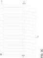
- FIG. 3C illustrates a perspective view of rectangular trench array configuration 300.
- Microchannels 317 and microchannels 327 may be substantially similar to microchannels 217 and 227 described above with reference to FIGs. 2A-2C . Accordingly, a detailed description of the geometry and spacing is not repeated for compactness.
- Outlets 110 may have a height of 113 and inlets 120 may have a height of 123.
- height 113 and height 123 may be approximately 20 ⁇ m and/or 50 ⁇ m. However, this is merely an example. The inventors surprisingly found that increasing height 113 and height 123 led to greater uniformity of pressure across surface 300.
- FIGs. 4A-4C illustrate trapezoidal trench array configuration 400.
- a surface 405 of the device 100 includes regularly spaced outlets 110 and inlets 120 formed as trenches.
- outlets 110 and inlets 120 may be configured in substantially trapezoidal trenches next to each other.
- Outlets 110 are disposed on microchannels 417 and inlets 120 are disposed on microchannels 427. Ends of microchannels 417 may be disposed on one side of the surface 405 and connect to pump 130, and connections ends of the microchannels 427 may be disposed on another side of the surface 405 and connect to pump 130.
- FIG. 4A shows a top view geometry of trapezoidal trench array configuration 400.
- the trenches 110 and 120 may be substantially equally distanced from each other, with alternating outlet 110 trench and inlet trench 120.
- All (or substantially all) fluid ejected from the outlets 110 will be divided between by the neighboring inlets 110.
- Edge outlet 410 and edge inlet 420 may be angled inwards towards a center of the surface to limit fringing of the hydrodynamic barrier, and/or size or shaped differently.
- edge outlet 410 and edge inlet 420 may have relatively less inflow or outflow (e.g., pressure) than inner outlets 110 and inlets 120.
- edge outlet 410 and edge inlet 420 may have approximately one-half the outflow and inflow as interior outlet 110 and interior inlet 120, respectively.
- edge outlet 410 and edge inlet 420 may have approximately one-half the outflow and inflow as interior outlet 110 and interior inlet 120, respectively.
- uneven pressure may be provided to various outlets and/or inlets to sample an environment, emit into the environment, or otherwise adjust the hydrodynamic barrier.
- FIG 4B illustrates a zoomed in configuration of one outlet 110 and one inlet 120.
- Outlet 110 is spaced a distance 431 from each inlet 120.
- distance 431 may be approximately 30 ⁇ m.
- Outlet 110 has a length 111, a first width 112a, and second width 112b, and inlet 120 has a length 121, a first width 122a, and second width 122b.
- Length 111 and length 121 may be substantially similar, width 112a and width 122a may be substantially similar, and width 112b and 122b may be substantially similar, but this is merely an example.
- length 111 and/or length 121 may be approximately 400 ⁇ m.
- Width 112a and/or width 122a may be approximately 10 ⁇ m. Width 112b and/or width 122b may be between 4 and 6 ⁇ m, for example, approximately 4, 5, 5.5, and/or 6 ⁇ m. Width 112b and/or width 122b of around 5.5 ⁇ m may be particularly useful. In other implementations, widths 112a and 122a may be approximately 20 ⁇ m, width 112b and 122b may be approximately 11 ⁇ m, and length 111 and length 121 may be approximately 60 ⁇ m-420 ⁇ m, e.g., 60, 120, and or 420 ⁇ m.
- FIG. 4C illustrates a perspective view of trapezoid trench array configuration 400.
- Microchannels 417 and microchannels 427 may be substantially similar to microchannels 217 and 227 described above with reference to FIGs. 2A-2C . Accordingly, a detailed description of the geometry and spacing is not repeated for compactness.
- Outlets 110 may have a height of 113 and inlets 120 may have a height of 123.
- height 113 and height 123 may be approximately 20 ⁇ m and/or 50 ⁇ m. However, this is merely an example.
- the inventors also surprisingly found that the use of trapezoidal trenches provided improved fluid-flow uniformity over rectangular trench and hole array designs.
- FIGs. 5A-5D illustrate a microneedle 510 disposed on a surface 505.
- Microneedle 510 incorporates outlets 110 and inlets 120 into a single form.
- Each microneedle 510 may be connected, for example to both an inlet microchannel and an outlet microchannel.
- microneedle has a substantially conical structure.
- Outlets 110 and inlets 120 are stacked on a front and back side of microneedle 510.
- Microneedle 510 may have a height 515, for example 800 ⁇ m. However, this is merely an example.
- a plurality of microneedles 510 may be applied each with different heights and/or arrangements and number of outlets 110 and inlets 120.
- microneedle may have various shapes and geometries and outlet 110 and inlet 120 positions.
- a microneedle may be substantially tetrahedronic, pyramidal. Or various other polygonal shapes.
- FIG. 5B illustrates a cross section of microneedle 510.
- a single outlet channel 512 is connected to all outlets 110, and a single inlet channel 514 is connected to all inlets 120, but this is merely an example.
- FIGs. 5C and 5D illustrate a simulation of hydrodynamic barrier 590 generated by pump 130 operating microneedle 510. The hydrodynamic barrier separates the microneedle from the outside water.
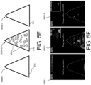
- FIGs. 5E and 5F illustrates operation of a microneedle 510 according to an example implementation.
- microneedle 510 is submerged in blood and fibrinogen (a clotting agent).
- fibrinogen a clotting agent
- 550e-1/550f-1 microneedle 510 is operating. Very little fibrinogen affixes to the surface of microneedle 510.
- 550e-2/550f-2 microneedle 510 stops operating. Fibrinogen 599 adheres to microneedle 510 once the hydrodynamic barrier ceases.
- 550e-3/550f-3 microneedle 510 re-operates, and the flow of fluid cleaning microneedle 510.
- the novel microneedle 510 design can, in some cases, prevent virtually all fluid (e.g., detergent or other cleaning agent) from escaping into a surrounding environment.
- fluid e.g., detergent or other cleaning agent
- outlet/inlet 110/120 geometries and positionings discussed herein are merely examples. It will be understood that can tune the outlet/inlet 110/120 geometries may be adjusted beyond those explicitly described to ensure desired (e.g., balanced) influx and outflux across the surface.
- inlets and/or outlets may be formed in various geometries, shapes, and objects.
- an objects surface may have embedded outlets 110 and inlets 120 such that a hydrodynamic barrier can be provided on any geometry, and demonstrated by the microneedle 510.
- FIGs. 6A-6C illustrate operation of a barrier device 100 according to an embodiment.
- barrier device 100 may include one or more of the configurations discussed above with reference to FIGs. 2A-5F , and/or alternative configurations as will be understood by one of ordinary skill in light of the present disclosure.
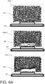
- FIG. 6A illustrates barrier device 100 establishing a hydrodynamic barrier.
- barrier device 100 is turned on after being off for an extended period of time such that no hydrodynamic barrier exists, and particles 698 and generally dispersed around barrier device 100.
- 600a-2 the hydrodynamic barrier is being established and particles 698 being moving from the surface of barrier device 100.
- 600a-3 the hydrodynamic barrier is established, separating barrier device 100 from particles 698 in a surrounding fluid.
- FIG. 6B illustrates a hydrodynamic barrier preventing impact by a current.
- a current is released.
- the current proceeds over device 100.
- the hydrodynamic barrier prevents the current from impacting the surface.
- FIG. 6C illustrates velocity fields of the current and the hydrodynamic barrier according to an example embodiment.
- magnetic and/or electrostatic fields may be used as a driving force (e.g., instead of pump 130).
- the magnetic/electric fields may generate similarly patterned field lines as a fluid creating a hydrodynamic layer. In terms of magnetic/electric field, this may be called surface-confined magnetic/electrostatic fields.
- magnetic and/or metallic particles may be applied and made to circular on or near the surface. For example, magnetic beads (micro-/nanoparticle) can be made to circulate near the surface by surface-confined magnetic field. This circulating motion of the beads can physically scrape and lyse any fouling biomaterials on the surface, while the constant motion minimizes attachment in the first place.
- the field may be induced either with alternating permanent magnets (NSNSNS %) or with electromagnetic (e.g., AC) fields.
- electromagnets may be used to "steer" magnetic particles across the surface (for example, by rapidly changing and/or moving a magnetic source.
- hydrodynamic barriers may be used to locally change surface characteristics of a surface.
- barrier device 100 may create a hydrodynamic air/fluid barrier to modify apparent surface friction of the underlying surface.
- an air barrier may more easily move through water than a typical hull surface.
- a fluid barrier e.g., hydrodynamic or bubble
- apparent surface roughness to a surrounding environment can be reduced.
- energy requirement of moving an object through an environment e.g., fuel consumption
- Such a system could have application in any types of moving surface, such as automobiles, planes, ships, space craft, tires, and/or propellers. As an example, this process can be thought of as similar to creating a barrier between an air hockey puck and a surface of an air hockey table.
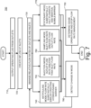
- FIG. 7 is a flowchart 700 of a method of operating a barrier device 100 according to an example embodiment.
- Barrier device 100 may be operated in accordance with flowchart 700
- barrier device 100 outputs 710 an operating fluid from a plurality of outlets (e.g., outlets 110).
- pump 130 may pump (e.g., under control of controller 150) an operating fluid from reservoir 140 through microchannels 217/317/417 to outlets 110.
- controller 150 may further select a reservoir 140 from a plurality of reservoirs, a specific fluid and/or a fluid mix to be the operating fluid, and control pump 130 to pump the corresponding fluid.
- Barrier device 100 may further create 720 an inflow at a plurality of inlets (e.g., inlets 120).
- pump 130 e.g., under control of controller 150
- pump 130 may simultaneously drive operating fluid to outlets 110 and create inflow at inlets 120.
- Barrier device 100 manages 730 the relative flow rates of outlets 110 and inlets 120 according to an operating mode.
- an antifouling mode or cleaning mode 740
- the flow rate passing each of outlets 110 is substantially similar to the flow rate passing each of inlets 120; thus, the operating fluid discharged by outlets 110 is substantially collected by inlets 120 and the hydrodynamic barrier is formed on the surface.
- injection mode 750
- the output from the outlets 110 is greater than the flow rate of the inlets 120, thereby discharging fluid outside of the device.
- sampling mode (760) the flow rate of the inlets 120 is greater than the flow rate of the outlets, thereby collecting fluid from a surrounding environment.
- stationary mode 770
- the external pump substantially stops operation and outlet 110 and inlet 120 flow.
- Barrier device 100 detects 780 a change of operating mode, and barrier device 100 managers 730 the relative flow rates of outlets 110 and inlets 120 according to the changed operating mode. If no change of mode is detected, barrier device 100 may eventually determine 790 operation is to cease, and stop managing flow rates.
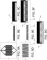
- FIGs. 9A-9G illustrate manufacturing a microchannel and trench cast 930 of a barrier device 100 according to an embodiment.
- FIGs, 9A-9G represent an example, non-limiting manufacturing technique using photolithography.
- microchannels 217/227 and outlets/inlets 110/120 may be fabricated in a number of ways, such as 3D lithography, 3D printing, and UV curable material.
- FIGs. 9A and 9B illustrate top and cross-cut views of a microchannel mold 910.
- Mold 910 may be fabricated, for example, using soft lithography on a silicon wafer.
- FIG. 9C illustrates a microchannel cast 915 that may be formed from microchannel mold 910, for example, by coating the mold 910 with polydimethylsiloxane (PDMS) (e.g., spin coating) and allowing the PDMS to cure.
- PDMS polydimethylsiloxane
- FIGs. 9D and 9E illustrates top and cross-cut views of outlet/inlet mold 920.
- Mold 920 may be fabricated, for example, using soft lithography on a silicon wafer. Although mold 920 as illustrated is for a trench array, this is merely an example.
- FIG. 9F illustrates an outlet/inlet cast 925 being formed from outlet/inlet mold 920, for example, by coating the mold 920 with polydimethylsiloxane (PDMS) (e.g., spin coating) and allowing the PDMS to cure.
- PDMS polydimethylsiloxane
- Microchannel cast 915 is aligned and bonded to outlet/inlet cast 925 (e.g., by treating microchannel cast 915 and/or outlet/inlet mold 925 with corona plasma and a few drops of ethanol to prevent irreversible bonding during alignment).
- the combined microchannel and trench cast 930 is formed ( FIG. 9G ) and a microchannel and trench can be generated for barrier device 100.
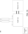
- FIG. 10 is a block diagram of a barrier device 1000 according to an embodiment.
- barrier device 1000 includes an outlet 110, an inlet 120, pump 130, reservoir 140, and controller 150.
- barrier device 1000 of FIG. 10 is substantially similar to barrier device 100 illustrated in FIG. 1 , except for barrier device 1000 of FIG. 10 only includes a single outlet 110 and a single inlet 120.
- Outlet 110, inlet 120, pump 130, reservoir 140, and controller 150 may function substantially similar to similar elements described above with reference to FIG. 1 . Accordingly, a detailed description is not repeated.
- FIG. 11 is a block diagram of a barrier device 1000 according to an embodiment.
- barrier device 1000 includes a plurality of outlets 110, a plurality of inlets 120, passive driver 1130 (e.g., an energy harvester), and reservoir 140.
- Outlets 110, inlets 120, and reservoir 140 may function substantially similar to similar elements described above with reference to FIG. 1 . Accordingly, a detailed description of these elements is not repeated herein.
- Barrier device 1000 includes passive driver 1130.
- Passive driver 1130 may be configured to harvest energy from an ambient environment to control the flow of an operating fluid from outlets 110 and into inlets 120.
- passive driver 1130 may be configured to harvest mechanical energy from the relative motion of barrier device to a surrounding environment (e.g., of a moving ship) to drive the inlets and outlets to circulate the operating fluid.
- passive driver 1130 may driver the outlets 110 and inlets 120 to generate a hydrodynamic barrier with an environmental fluid from a surrounding environment.
- FIG. 12 is a block diagram of a barrier device 1200 according to an embodiment.
- barrier device 1200 includes a porous material 1250 (e.g., naturally porous material, such as a hydrogel), pump 130, reservoir 140, and controller 150. Pump 130, reservoir 140, and controller 150 may function substantially similar to similar elements described above with reference to FIG. 1 . Accordingly, a detailed description of these elements is not repeated herein.
- Barrier device 1200 includes porous material 1250. Porous material 1250 may function as outlets 110, inlets 120, and/or both. As a non-limiting example, porous material 1250 may be disposed on a surface, and fluidly connected to pump 130.
- Pump 130 may pump an operating fluid out of porous material 1250, and/or draw environmental fluid into porous material 1250.
- pump 130 may maintain a layer of the operating fluid (e.g., a bubble layer) on a surface of porous material 1250.
- pump 130 may rapidly switch from pumping out to pumping in to generate and maintain a protective layer of the operating fluid on the surface.
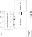
- FIG. 13 is a block diagram of a barrier device 1300 according to an embodiment.
- barrier device 1300 includes a porous material 1250, secondary holes 1360, pump 130, reservoir 140, and controller 150. Pump 130, reservoir 140, and controller 150 may function substantially similar to similar elements described above with reference to FIG. 1 . Accordingly, a detailed description of these elements is not repeated herein.
- Barrier device 13000 includes porous material 1250, which may be substantially simlar to the porous material 1250 described with reference to FIG. 12 , and may function as outlets 110, inlets 120, and/or both.
- Barrier device 1300 further includes secondary holes 1360 which may also function as outlets 110, inlets 120, and/or both. For example, secondary holes 1360 may operate as outlets 110, and porous material 1250 may operate as inlets 120 such that a hydrodynamic barrier is maintained on the surface.
- barrier device 100 Although the present disclosure regularly refers to barrier device 100, one of ordinary skill will recognize in light of the present disclosure that similar features, discussions, and examples may be applied to barrier devices 1000, 1100, 1200, and 1300 unless explicitly disclaimed or inherently incompatible.
- the computing device architecture 800 includes a central processing unit (CPU) 802, where computer instructions are processed; a display interface 804 that acts as a communication interface and provides functions for rendering video, graphics, images, and texts on the display.
- the display interface 804 may be directly connected to a local display, such as a touch-screen display associated with a mobile computing device.
- the display interface 804 may be configured for providing data, images, and other information for an external/remote display that is not necessarily physically connected to the mobile computing device.
- a desktop monitor may be utilized for mirroring graphics and other information that is presented on a mobile computing device.
- the display interface 804 may wirelessly communicate, for example, via a Wi-Fi channel or other available network connection interface 812 to the external/remote display.
- the network connection interface 812 may be configured as a communication interface and may provide functions for rendering video, graphics, images, text, other information, or any combination thereof on the display.
- a communication interface may include a serial port, a parallel port, a general purpose input and output (GPIO) port, a game port, a universal serial bus (USB), a micro-USB port, a high definition multimedia (HDMI) port, a video port, an audio port, a Bluetooth port, a near field communication (NFC) port, another like communication interface, or any combination thereof.
- the display interface 804 may be operatively coupled to a local display, such as a touch-screen display associated with a mobile device.
- the display interface 804 may be configured to provide video, graphics, images, text, other information, or any combination thereof for an external/remote display that is not necessarily connected to the mobile computing device.
- a desktop monitor may be utilized for mirroring or extending graphical information that may be presented on a mobile device.
- the display interface 804 may wirelessly communicate, for example, via the network connection interface 812 such as a Wi-Fi transceiver to the external/remote display.
- the computing device architecture 800 may include a keyboard interface 806 that provides a communication interface to a keyboard.
- the computing device architecture 800 may include a presence-sensitive display interface 808 for connecting to a presence-sensitive display 807.
- the presence-sensitive display interface 808 may provide a communication interface to various devices such as a pointing device, a touch screen, a depth camera, etc. which may or may not be associated with a display.
- the computing device architecture 800 may be configured to use an input device via one or more of input/output interfaces (for example, the keyboard interface 806, the display interface 804, the presence sensitive display interface 808, network connection interface 812, camera interface 814, sound interface 816, etc.,) to allow a user to capture information into the computing device architecture 800.
- the input device may include a mouse, a trackball, a directional pad, a track pad, a touch-verified track pad, a presence-sensitive track pad, a presence-sensitive display, a scroll wheel, a digital camera, a digital video camera, a web camera, a microphone, a sensor, a smartcard, and the like.
- the input device may be integrated with the computing device architecture 800 or may be a separate device.
- the input device may be an accelerometer, a magnetometer, a digital camera, a microphone, and an optical sensor.
- Example implementations of the computing device architecture 800 may include an antenna interface 810 that provides a communication interface to an antenna; a network connection interface 812 that provides a communication interface to a network.
- the display interface 804 may be in communication with the network connection interface 812, for example, to provide information for display on a remote display that is not directly connected or attached to the system.
- a camera interface 814 is provided that acts as a communication interface and provides functions for capturing digital images from a camera.
- a sound interface 816 is provided as a communication interface for converting sound into electrical signals using a microphone and for converting electrical signals into sound using a speaker.
- a random-access memory (RAM) 818 is provided, where computer instructions and data may be stored in a volatile memory device for processing by the CPU 802.
- the computing device architecture 800 includes a read-only memory (ROM) 820 where invariant low-level system code or data for basic system functions such as basic input and output (I/O), startup, or reception of keystrokes from a keyboard are stored in a non-volatile memory device.
- ROM read-only memory
- I/O basic input and output
- the computing device architecture 800 includes a storage medium 822 or other suitable type of memory (e.g.
- the computing device architecture 800 includes a power source 830 that provides an appropriate alternating current (AC) or direct current (DC) to power components.
- AC alternating current
- DC direct current
- the computing device architecture 800 includes and a telephony subsystem 832 that allows the device 800 to transmit and receive sound over a telephone network.
- the constituent devices and the CPU 802 communicate with each other over a bus 834.
- the CPU 802 has appropriate structure to be a computer processor.
- the CPU 802 may include more than one processing unit.
- the RAM 818 interfaces with the computer bus 834 to provide quick RAM storage to the CPU 802 during the execution of software programs such as the operating system application programs, and device drivers. More specifically, the CPU 802 loads computer-executable process steps from the storage medium 822 or other media into a field of the RAM 818 in order to execute software programs. Data may be stored in the RAM 818, where the data may be accessed by the computer CPU 802 during execution.
- the device architecture 800 includes at least 88 MB of RAM, and 256 MB of flash memory.
- the storage medium 822 itself may include a number of physical drive units, such as a redundant array of independent disks (RAID), a floppy disk drive, a flash memory, a USB flash drive, an external hard disk drive, thumb drive, pen drive, key drive, a High-Density Digital Versatile Disc (HD-DVD) optical disc drive, an internal hard disk drive, a Blu-Ray optical disc drive, or a Holographic Digital Data Storage (HDDS) optical disc drive, an external mini-dual inline memory module (DIMM) synchronous dynamic random access memory (SDRAM), or an external micro-DIMM SDRAM.
- RAID redundant array of independent disks
- HD-DVD High-Density Digital Versatile Disc
- HD-DVD High-Density Digital Versatile Disc
- HDDS Holographic Digital Data Storage
- DIMM mini-dual inline memory module
- SDRAM synchronous dynamic random access memory
- micro-DIMM SDRAM an external micro-DIMM SDRAM
- Such computer readable storage media allow a computing device to access computer-executable process steps, application programs and the like, stored on removable and non-removable memory media, to off-load data from the device or to upload data onto the device.
- a computer program product such as one utilizing a communication system may be tangibly embodied in storage medium 822, which may include a machine-readable storage medium.
- the term computing device may be a CPU, or conceptualized as a CPU (for example, the CPU 802 of FIG. 8 ).
- the computing device (CPU) may be coupled, connected, and/or in communication with one or more peripheral devices, such as display.
- the term computing device may refer to a mobile computing device such as a smartphone, tablet computer, or smart watch.
- the computing device may output content to its local display and/or speaker(s).
- the computing device may output content to an external display device (e.g., over Wi-Fi) such as a TV or an external computing system.
- a computing device may include any number of hardware and/or software applications that are executed to facilitate any of the operations.
- one or more I/O interfaces may facilitate communication between the computing device and one or more input/output devices.
- a universal serial bus port, a serial port, a disk drive, a CD-ROM drive, and/or one or more user interface devices such as a display, keyboard, keypad, mouse, control panel, touch screen display, microphone, etc.
- the one or more I/O interfaces may be utilized to receive or collect data and/or user instructions from a wide variety of input devices. Received data may be processed by one or more computer processors as desired in various implementations of the disclosed technology and/or stored in one or more memory devices.
- One or more network interfaces may facilitate connection of the computing device inputs and outputs to one or more suitable networks and/or connections; for example, the connections that facilitate communication with any number of sensors associated with the system.
- the one or more network interfaces may further facilitate connection to one or more suitable networks; for example, a local area network, a wide area network, the Internet, a cellular network, a radio frequency network, a Bluetooth enabled network, a Wi-Fi enabled network, a satellite-based network any wired network, any wireless network, etc., for communication with external devices and/or systems.
Landscapes
- Engineering & Computer Science (AREA)
- Mechanical Engineering (AREA)
- General Engineering & Computer Science (AREA)
- Chemical & Material Sciences (AREA)
- Health & Medical Sciences (AREA)
- Dispersion Chemistry (AREA)
- Analytical Chemistry (AREA)
- General Health & Medical Sciences (AREA)
- Hematology (AREA)
- Clinical Laboratory Science (AREA)
- Chemical Kinetics & Catalysis (AREA)
- Physical Or Chemical Processes And Apparatus (AREA)
Claims (15)
- Verfahren zum Erzeugen einer hydrodynamischen Barriere aus einem Betriebsfluid auf einer Oberfläche (205), wobei das Verfahren Folgendes umfasst:Ausgeben des Betriebsfluids durch eine Vielzahl von Auslässen (110), die an der Oberfläche (205, 305, 405, 505) angeordnet sind; undgleichzeitig mit dem Ausgeben, Entziehen des Betriebsfluids durch eine Vielzahl von Einlässen (120), die an der Oberfläche (205, 305, 405, 505) angeordnet sind, dadurch Erzeugen einer hydrodynamischen Barriere an der Oberfläche mit der Bewegung des Betriebsfluids,wobei die Vielzahl von Auslässen (110) eine Vielzahl von im Wesentlichen trapezförmigen Auslassgräben umfasst, die an der Oberfläche (405) angeordnet sind, undwobei die Vielzahl von Einlässen (120) eine Vielzahl von im Wesentlichen trapezförmigen Einlassgräben umfasst, die an der Oberfläche (405) angeordnet sind, wobei die Einlassgräben und die Auslassgräben in einem abwechselnden Muster angeordnet sind.
- Verfahren nach Anspruch 1, ferner umfassend:Auswählen eines Betriebsfluids aus einer Vielzahl von Betriebsfluiden, wobei die Vielzahl von Betriebsfluiden eines oder mehrere von einem emittierbaren Fluid, einem hydrophoben Fluid, Mikrokügelchen, Metallspänen, magnetischem Material, sterilen Lösungen, Lösungsmitteln und Reinigungslösungen umfasst; undAusgeben des ausgewählten Betriebsfluids.
- Verfahren nach Anspruch 1 oder 2, ferner umfassend:Auswählen eines Betriebsmodus aus einer Vielzahl von Betriebsmodi; undAufrechterhalten der relativen Strömungsraten zwischen der Vielzahl von Auslässen (110) und der Vielzahl von Einlässen (120) basierend auf dem ausgewählten Betriebsmodus.
- Verfahren nach Anspruch 3, wobei die Vielzahl von Betriebsmodi mindestens einen der Folgenden umfasst:einen Antifouling-Modus (740), der Aufrechterhalten einer wesentlichen Gleichwertigkeit zwischen einer Strömungsrate des Betriebsfluids durch die Vielzahl von Auslässen (110) und einer Strömungsrate des Betriebsfluid durch die Vielzahl von Einlässen (120) umfasst;einen Injektionsmodus (750), der Aufrechterhalten der Strömungsrate des Betriebsfluids durch die Vielzahl von Auslässen (110) als größer als die Strömungsrate des Betriebsfluids durch die Vielzahl von Einlässen (120) umfasst, sodass ein Teil des Betriebsfluids in eine umliegende Umgebung freigesetzt wird;einen Probenahmemodus (760), der Aufrechterhalten der Strömungsrate des Betriebsfluids durch die Vielzahl von Auslässen (110) als kleiner als die Strömungsrate des Betriebsfluids durch die Vielzahl von Einlässen (120) umfasst, sodass ein Teil des Umgebungsfluids aus der umliegenden Umgebung entzogen wird; undeinen Umschaltmodus (770), der dazu konfiguriert ist, zumindest eine von der Strömungsrate des Betriebsfluids durch die Vielzahl von Auslässen (110) und der Strömungsrate des Betriebsfluids durch die Vielzahl von Einlässen (120) im Zeitverlauf zu modifizieren.
- Verfahren nach Anspruch 4, wobei der Umschaltmodus (770) dazu konfiguriert ist, zwischen dem Injektionsmodus (750) und dem Probenahmemodus (760) umzuschalten.
- Verfahren nach einem der Ansprüche 1 bis 5, ferner umfassend Reinigen der Oberfläche (205, 305, 405, 505) durch Ändern mindestens eines von einem Betriebsfluid, einer Strömungsrate der Vielzahl von Auslässen (110) und einer Strömungsrate der Vielzahl von Einlässen (120).
- Verfahren nach einem der Ansprüche 1 bis 6, wobei eine Pumpe (130) in Fluidkommunikation mit der Vielzahl von Auslässen (110) und der Vielzahl von Einlässen (120) steht, und
wobei die Pumpe dazu konfiguriert ist, eine auf die Oberfläche beschränkte hydrodynamische Barriere auf der Oberfläche (205, 305, 405, 505) zu bilden, indem sie gleichzeitig das Betriebsfluid aus der Vielzahl von Auslässen (110) pumpt und das Betriebsfluid durch die Vielzahl von Einlässen entzieht. - Verfahren nach Anspruch 3, wobei:eine Pumpe (130) in Fluidkommunikation mit der Vielzahl von Auslässen (110) und der Vielzahl von Einlässen (120) steht, undeine Steuerung (150) dazu konfiguriert ist, die Pumpe (130) so zu steuern, dass sie in der Vielzahl von Betriebsmodi (740, 750, 760, 770) betrieben wird.
- Verfahren nach einem der Ansprüche 1 bis 8, wobei das Betriebsfluid auf die Oberfläche beschränkt wird, indem der Betriebsfluidstrom in einem laminaren Zustand gehalten wird.
- Hydrodynamische Barrierevorrichtung (100), umfassend:eine Vielzahl von Auslässen (110), die auf einer Oberfläche (205) angeordnet sind;eine Vielzahl von Einlässen (120), die zwischen der Vielzahl von Auslässen (110) verteilt und auf der Oberfläche (205, 305, 405, 505) angeordnet sind; undeine Pumpe (130) in Fluidkommunikation mit der Vielzahl von Auslässen (110) und der Vielzahl von Einlässen (120),wobei die Pumpe (130) dazu konfiguriert ist, eine hydrodynamische Barriere auf der Oberfläche (205, 305, 405, 505) zu erzeugen, indem sie gleichzeitig ein Betriebsfluid aus der Vielzahl von Auslässen (110) pumpt und das Betriebsfluid durch die Vielzahl von Einlässen (120) zurückzieht, um die hydrodynamische Barriere auf der Oberfläche (250) zu erzeugen,wobei die Vielzahl von Auslässen (110) eine Vielzahl von im Wesentlichen trapezförmigen Auslassgräben umfasst, die an der Oberfläche (405) angeordnet sind, undwobei die Vielzahl von Einlässen (120) eine Vielzahl von im Wesentlichen trapezförmigen Einlassgräben umfasst, die an der Oberfläche (405) angeordnet sind, wobei die Einlassgräben und die Auslassgräben in einem abwechselnden Muster angeordnet sind.
- Hydrodynamische Barrierevorrichtung (100) nach Anspruch 10, ferner mindestens einen Behälter (140) umfassend, der dazu konfiguriert ist, mindestens einen Teil des Betriebsfluid zu speichern.
- Hydrodynamische Barrierevorrichtung (100) nach Anspruch 10 oder 11, ferner eine Steuerung (150) umfassend, die dazu konfiguriert ist, die Pumpe (130) so zu steuern, dass sie in einer Vielzahl von Betriebsmodi (740, 750, 760, 770) betrieben wird, und optional
wobei die Vielzahl von Betriebsmodi mindestens einen der Folgenden umfasst:einen Antifouling-Modus (740), der zum Aufrechterhalten einer wesentlichen Gleichwertigkeit zwischen einer Strömungsrate des Betriebsfluids durch die Vielzahl von Auslässen (110) und einer Strömungsrate des Betriebsfluid durch die Vielzahl von Einlässen (120) konfiguriert ist;einen Injektionsmodus (750), der zum Aufrechterhalten der Strömungsrate des Betriebsfluids durch die Vielzahl von Auslässen (110) als größer als die Strömungsrate des Betriebsfluids durch die Vielzahl von Einlässen (120) konfiguriert ist, sodass ein Teil des Betriebsfluids in eine umliegende Umgebung freigesetzt wird;einen Probenahmemodus (760), der zum Aufrechterhalten der Strömungsrate des Betriebsfluids durch die Vielzahl von Auslässen (110) als kleiner als die Strömungsrate des Betriebsfluids durch die Vielzahl von Einlässen (120) konfiguriert ist, sodass ein Teil des Umgebungsfluids aus der umliegenden Umgebung in die Vielzahl von Einlässen (120) entzogen wird; undeinen Umschaltmodus (770), der dazu konfiguriert ist, zumindest eine von der Strömungsrate des Betriebsfluids durch die Vielzahl von Auslässen (110) und der Strömungsrate des Betriebsfluids durch die Vielzahl von Einlässen (120) im Zeitverlauf zu modifizieren, und optionalwobei der Umschaltmodus (770) dazu konfiguriert ist, zwischen dem Injektionsmodus (750) und dem Probenahmemodus (760) umzuschalten. - Hydrodynamische Barrierevorrichtung (100) nach einem der Ansprüche 10 bis 12, wobei das Betriebsfluid mindestens eines von einem emittierbaren Fluid, einem hydrophoben Fluid, Mikrokügelchen, Metallspänen, magnetischem Material, sterilen Lösungen, Lösungsmitteln und Reinigungslösungen umfasst.
- Hydrodynamische Barrierevorrichtung (100) nach den Ansprüchen 10 bis 13, wobei die Pumpe eine Peristaltikpumpe, eine Spritzenpumpe oder eine pneumatische Pumpe umfasst, oder
wobei das Betriebsfluid von einer um die Oberfläche liegenden Umgebung gewonnen wird. - Hydrodynamische Barrierevorrichtung (100) nach den Ansprüchen 10 bis 14, wobei die Vielzahl von Auslässen, die Vielzahl von Einlässen oder sowohl die Vielzahl von Auslässen als auch die Vielzahl von Einlässen Poren in einem porösen Material (1250) umfassen, das auf der Oberfläche angeordnet ist, und optional
wobei das poröse Material (1250) ein Hydrogel umfasst.
Applications Claiming Priority (2)
| Application Number | Priority Date | Filing Date | Title |
|---|---|---|---|
| US201862635616P | 2018-02-27 | 2018-02-27 | |
| PCT/US2019/019862 WO2019169005A1 (en) | 2018-02-27 | 2019-02-27 | System, devices, and methods providing hydrodynamic barriers |
Publications (3)
| Publication Number | Publication Date |
|---|---|
| EP3759463A1 EP3759463A1 (de) | 2021-01-06 |
| EP3759463A4 EP3759463A4 (de) | 2021-11-24 |
| EP3759463B1 true EP3759463B1 (de) | 2025-03-26 |
Family
ID=67806391
Family Applications (1)
| Application Number | Title | Priority Date | Filing Date |
|---|---|---|---|
| EP19760033.1A Active EP3759463B1 (de) | 2018-02-27 | 2019-02-27 | System, vorrichtungen und verfahren zur bereitstellung von hydrodynamischen barrieren |
Country Status (6)
| Country | Link |
|---|---|
| US (1) | US12103001B2 (de) |
| EP (1) | EP3759463B1 (de) |
| KR (1) | KR20210011905A (de) |
| CN (1) | CN112154316B (de) |
| AU (1) | AU2019228505B2 (de) |
| WO (1) | WO2019169005A1 (de) |
Family Cites Families (14)
| Publication number | Priority date | Publication date | Assignee | Title |
|---|---|---|---|---|
| US4562867A (en) * | 1978-11-13 | 1986-01-07 | Bowles Fluidics Corporation | Fluid oscillator |
| DE4105967C2 (de) * | 1990-04-27 | 1993-11-25 | Heidelberger Druckmasch Ag | Bogenanleger mit Blasdüsen zur Erzeugung von Tragluft unter dem oberen, vom Bogenstapel abgehobenen Bogen |
| US5494299A (en) * | 1994-02-22 | 1996-02-27 | Evironamics Corporation | Temperature and pressure resistant rotating seal construction for a pump |
| US6902703B2 (en) | 1999-05-03 | 2005-06-07 | Ljl Biosystems, Inc. | Integrated sample-processing system |
| TWI515770B (zh) * | 2003-06-19 | 2016-01-01 | 尼康股份有限公司 | An exposure apparatus, an exposure method, and an element manufacturing method |
| GB0316584D0 (en) * | 2003-07-16 | 2003-08-20 | Xaar Technology Ltd | Droplet deposition apparatus |
| DE602004030481D1 (de) * | 2003-12-15 | 2011-01-20 | Nippon Kogaku Kk | Bühnensystem, belichtungsvorrichtung und belichtungsverfahren |
| JP4767251B2 (ja) | 2004-04-14 | 2011-09-07 | コアフロー サイエンティフィック ソリューションズ リミテッド | 光学検査装置を平坦な対象物の接面に対して焦点合わせする方法 |
| AT501192B1 (de) | 2004-12-23 | 2007-04-15 | Lisec Peter | Vorrichtung zum transportieren und stützen tafelförmiger gegenstände, insbesondere glastafeln |
| US7802592B2 (en) * | 2006-04-18 | 2010-09-28 | Fisher Controls International, Llc | Fluid pressure reduction devices |
| NO325803B1 (no) * | 2006-10-13 | 2008-07-21 | Framo Eng As | Anordning ved tetningssystem |
| US8592221B2 (en) * | 2007-04-19 | 2013-11-26 | Brandeis University | Manipulation of fluids, fluid components and reactions in microfluidic systems |
| WO2009122399A1 (en) * | 2008-03-31 | 2009-10-08 | Technion Research & Development Foundation Ltd. | Method and system for manipulating fluid medium |
| CN105627808A (zh) * | 2015-12-31 | 2016-06-01 | 北京航空航天大学 | 一种新型换热器芯体和分流结构 |
-
2019
- 2019-02-27 EP EP19760033.1A patent/EP3759463B1/de active Active
- 2019-02-27 WO PCT/US2019/019862 patent/WO2019169005A1/en not_active Ceased
- 2019-02-27 AU AU2019228505A patent/AU2019228505B2/en active Active
- 2019-02-27 CN CN201980028671.XA patent/CN112154316B/zh active Active
- 2019-02-27 US US16/975,498 patent/US12103001B2/en active Active
- 2019-02-27 KR KR1020207028026A patent/KR20210011905A/ko not_active Withdrawn
Also Published As
| Publication number | Publication date |
|---|---|
| CA3095734A1 (en) | 2019-09-06 |
| EP3759463A4 (de) | 2021-11-24 |
| CN112154316B (zh) | 2025-03-11 |
| US12103001B2 (en) | 2024-10-01 |
| KR20210011905A (ko) | 2021-02-02 |
| AU2019228505B2 (en) | 2024-01-04 |
| US20210069700A1 (en) | 2021-03-11 |
| EP3759463A1 (de) | 2021-01-06 |
| AU2019228505A1 (en) | 2020-10-15 |
| WO2019169005A1 (en) | 2019-09-06 |
| CN112154316A (zh) | 2020-12-29 |
Similar Documents
| Publication | Publication Date | Title |
|---|---|---|
| Darhuber et al. | Principles of microfluidic actuation by modulation of surface stresses | |
| US10710072B2 (en) | Particle separation apparatus and particle separation method | |
| CN105050718B (zh) | 形成相对单分散液滴的装置和方法 | |
| Patel et al. | Lateral cavity acoustic transducer as an on-chip cell/particle microfluidic switch | |
| Chung et al. | Droplet dynamics passing through obstructions in confined microchannel flow | |
| Kavousanakis et al. | How to achieve reversible electrowetting on superhydrophobic surfaces | |
| TW201720523A (zh) | 用於微流體裝置之流體通道 | |
| WO2017187284A1 (en) | Vertical microfluidic probe head with large scale surface processing apertures | |
| Vanapalli et al. | Fluidic assembly and packing of microspheres in confined channels | |
| EP3759463B1 (de) | System, vorrichtungen und verfahren zur bereitstellung von hydrodynamischen barrieren | |
| US20050045539A1 (en) | Control device and method for controlling liquid droplets | |
| Lao et al. | A microfluidic platform for formation of double-emulsion droplets | |
| Pelizzari et al. | Droplet self-propulsion on slippery liquid-infused surfaces with dual-lubricant wedge-shaped wettability patterns | |
| CA3095734C (en) | System, devices, and methods providing hydrodynamic barriers | |
| CN104388301B (zh) | 基于流体力学的单细胞高效捕获器件和系统 | |
| Lee et al. | Conformal hydrogel-skin coating on a microfluidic channel through microstamping transfer of the masking layer | |
| US20120258529A1 (en) | Apparatus for separating target molecules and method of separating target molecules by using the same | |
| Zheng et al. | Microfluidic step emulsification with parallel nozzles on a vertical slit | |
| Li et al. | Janus droplets and droplets with multiple heterogeneous surface strips generated with nanoparticles under applied electric field | |
| US11666938B2 (en) | Liquid patterning device and method | |
| WO2018017120A1 (en) | Microfluidic devices | |
| Wu et al. | Extraordinarily rapid rise of tiny bubbles sliding beneath superhydrophobic surfaces | |
| Hsu et al. | Biocompatible magnetic nanocomposite microcapsules as microfluidic one-way diffusion blocking valves with ultra-low opening pressure | |
| So et al. | Refillable and magnetically actuated drug delivery system using pear-shaped viscoelastic membrane | |
| KR101718491B1 (ko) | 액체 패터닝 장치 |
Legal Events
| Date | Code | Title | Description |
|---|---|---|---|
| STAA | Information on the status of an ep patent application or granted ep patent |
Free format text: STATUS: THE INTERNATIONAL PUBLICATION HAS BEEN MADE |
|
| PUAI | Public reference made under article 153(3) epc to a published international application that has entered the european phase |
Free format text: ORIGINAL CODE: 0009012 |
|
| STAA | Information on the status of an ep patent application or granted ep patent |
Free format text: STATUS: REQUEST FOR EXAMINATION WAS MADE |
|
| 17P | Request for examination filed |
Effective date: 20200928 |
|
| AK | Designated contracting states |
Kind code of ref document: A1 Designated state(s): AL AT BE BG CH CY CZ DE DK EE ES FI FR GB GR HR HU IE IS IT LI LT LU LV MC MK MT NL NO PL PT RO RS SE SI SK SM TR |
|
| AX | Request for extension of the european patent |
Extension state: BA ME |
|
| DAV | Request for validation of the european patent (deleted) | ||
| DAX | Request for extension of the european patent (deleted) | ||
| RIN1 | Information on inventor provided before grant (corrected) |
Inventor name: SARIOGLU, ALI FATIH Inventor name: LEE, DOHWAN |
|
| REG | Reference to a national code |
Ref country code: DE Free format text: PREVIOUS MAIN CLASS: G01N0013000000 Ref country code: DE Ref legal event code: R079 Ref document number: 602019067796 Country of ref document: DE Free format text: PREVIOUS MAIN CLASS: G01N0013000000 Ipc: F04B0023020000 |
|
| A4 | Supplementary search report drawn up and despatched |
Effective date: 20211025 |
|
| RIC1 | Information provided on ipc code assigned before grant |
Ipc: F04B 43/12 20060101ALI20211020BHEP Ipc: F04B 53/16 20060101ALI20211020BHEP Ipc: F04B 23/02 20060101AFI20211020BHEP |
|
| RAP3 | Party data changed (applicant data changed or rights of an application transferred) |
Owner name: GEORGIA TECH RESEARCH CORPORATION |
|
| P01 | Opt-out of the competence of the unified patent court (upc) registered |
Effective date: 20230502 |
|
| STAA | Information on the status of an ep patent application or granted ep patent |
Free format text: STATUS: EXAMINATION IS IN PROGRESS |
|
| 17Q | First examination report despatched |
Effective date: 20230725 |
|
| GRAP | Despatch of communication of intention to grant a patent |
Free format text: ORIGINAL CODE: EPIDOSNIGR1 |
|
| STAA | Information on the status of an ep patent application or granted ep patent |
Free format text: STATUS: GRANT OF PATENT IS INTENDED |
|
| RIC1 | Information provided on ipc code assigned before grant |
Ipc: B08B 17/00 20060101ALN20241209BHEP Ipc: F04B 53/16 20060101ALI20241209BHEP Ipc: F04B 43/12 20060101ALI20241209BHEP Ipc: F04B 23/02 20060101AFI20241209BHEP |
|
| INTG | Intention to grant announced |
Effective date: 20250113 |
|
| GRAS | Grant fee paid |
Free format text: ORIGINAL CODE: EPIDOSNIGR3 |
|
| GRAA | (expected) grant |
Free format text: ORIGINAL CODE: 0009210 |
|
| STAA | Information on the status of an ep patent application or granted ep patent |
Free format text: STATUS: THE PATENT HAS BEEN GRANTED |
|
| AK | Designated contracting states |
Kind code of ref document: B1 Designated state(s): AL AT BE BG CH CY CZ DE DK EE ES FI FR GB GR HR HU IE IS IT LI LT LU LV MC MK MT NL NO PL PT RO RS SE SI SK SM TR |
|
| REG | Reference to a national code |
Ref country code: GB Ref legal event code: FG4D |
|
| REG | Reference to a national code |
Ref country code: CH Ref legal event code: EP |
|
| REG | Reference to a national code |
Ref country code: DE Ref legal event code: R096 Ref document number: 602019067796 Country of ref document: DE |
|
| REG | Reference to a national code |
Ref country code: IE Ref legal event code: FG4D |
|
| PG25 | Lapsed in a contracting state [announced via postgrant information from national office to epo] |
Ref country code: RS Free format text: LAPSE BECAUSE OF FAILURE TO SUBMIT A TRANSLATION OF THE DESCRIPTION OR TO PAY THE FEE WITHIN THE PRESCRIBED TIME-LIMIT Effective date: 20250626 |
|
| PG25 | Lapsed in a contracting state [announced via postgrant information from national office to epo] |
Ref country code: FI Free format text: LAPSE BECAUSE OF FAILURE TO SUBMIT A TRANSLATION OF THE DESCRIPTION OR TO PAY THE FEE WITHIN THE PRESCRIBED TIME-LIMIT Effective date: 20250326 |
|
| REG | Reference to a national code |
Ref country code: LT Ref legal event code: MG9D |
|
| PG25 | Lapsed in a contracting state [announced via postgrant information from national office to epo] |
Ref country code: NO Free format text: LAPSE BECAUSE OF FAILURE TO SUBMIT A TRANSLATION OF THE DESCRIPTION OR TO PAY THE FEE WITHIN THE PRESCRIBED TIME-LIMIT Effective date: 20250626 |
|
| PG25 | Lapsed in a contracting state [announced via postgrant information from national office to epo] |
Ref country code: HR Free format text: LAPSE BECAUSE OF FAILURE TO SUBMIT A TRANSLATION OF THE DESCRIPTION OR TO PAY THE FEE WITHIN THE PRESCRIBED TIME-LIMIT Effective date: 20250326 |
|
| PG25 | Lapsed in a contracting state [announced via postgrant information from national office to epo] |
Ref country code: LV Free format text: LAPSE BECAUSE OF FAILURE TO SUBMIT A TRANSLATION OF THE DESCRIPTION OR TO PAY THE FEE WITHIN THE PRESCRIBED TIME-LIMIT Effective date: 20250326 |
|
| PG25 | Lapsed in a contracting state [announced via postgrant information from national office to epo] |
Ref country code: GR Free format text: LAPSE BECAUSE OF FAILURE TO SUBMIT A TRANSLATION OF THE DESCRIPTION OR TO PAY THE FEE WITHIN THE PRESCRIBED TIME-LIMIT Effective date: 20250627 Ref country code: BG Free format text: LAPSE BECAUSE OF FAILURE TO SUBMIT A TRANSLATION OF THE DESCRIPTION OR TO PAY THE FEE WITHIN THE PRESCRIBED TIME-LIMIT Effective date: 20250326 |
|
| REG | Reference to a national code |
Ref country code: NL Ref legal event code: MP Effective date: 20250326 |
|
| PG25 | Lapsed in a contracting state [announced via postgrant information from national office to epo] |
Ref country code: NL Free format text: LAPSE BECAUSE OF FAILURE TO SUBMIT A TRANSLATION OF THE DESCRIPTION OR TO PAY THE FEE WITHIN THE PRESCRIBED TIME-LIMIT Effective date: 20250326 |
|
| PG25 | Lapsed in a contracting state [announced via postgrant information from national office to epo] |
Ref country code: SE Free format text: LAPSE BECAUSE OF FAILURE TO SUBMIT A TRANSLATION OF THE DESCRIPTION OR TO PAY THE FEE WITHIN THE PRESCRIBED TIME-LIMIT Effective date: 20250326 |
|
| REG | Reference to a national code |
Ref country code: AT Ref legal event code: MK05 Ref document number: 1779207 Country of ref document: AT Kind code of ref document: T Effective date: 20250326 |
|
| PG25 | Lapsed in a contracting state [announced via postgrant information from national office to epo] |
Ref country code: SM Free format text: LAPSE BECAUSE OF FAILURE TO SUBMIT A TRANSLATION OF THE DESCRIPTION OR TO PAY THE FEE WITHIN THE PRESCRIBED TIME-LIMIT Effective date: 20250326 |
|
| PG25 | Lapsed in a contracting state [announced via postgrant information from national office to epo] |
Ref country code: PT Free format text: LAPSE BECAUSE OF FAILURE TO SUBMIT A TRANSLATION OF THE DESCRIPTION OR TO PAY THE FEE WITHIN THE PRESCRIBED TIME-LIMIT Effective date: 20250728 Ref country code: ES Free format text: LAPSE BECAUSE OF FAILURE TO SUBMIT A TRANSLATION OF THE DESCRIPTION OR TO PAY THE FEE WITHIN THE PRESCRIBED TIME-LIMIT Effective date: 20250326 |
|
| PG25 | Lapsed in a contracting state [announced via postgrant information from national office to epo] |
Ref country code: PL Free format text: LAPSE BECAUSE OF FAILURE TO SUBMIT A TRANSLATION OF THE DESCRIPTION OR TO PAY THE FEE WITHIN THE PRESCRIBED TIME-LIMIT Effective date: 20250326 Ref country code: IT Free format text: LAPSE BECAUSE OF FAILURE TO SUBMIT A TRANSLATION OF THE DESCRIPTION OR TO PAY THE FEE WITHIN THE PRESCRIBED TIME-LIMIT Effective date: 20250326 |
|
| PG25 | Lapsed in a contracting state [announced via postgrant information from national office to epo] |
Ref country code: AT Free format text: LAPSE BECAUSE OF FAILURE TO SUBMIT A TRANSLATION OF THE DESCRIPTION OR TO PAY THE FEE WITHIN THE PRESCRIBED TIME-LIMIT Effective date: 20250326 |
|
| PG25 | Lapsed in a contracting state [announced via postgrant information from national office to epo] |
Ref country code: EE Free format text: LAPSE BECAUSE OF FAILURE TO SUBMIT A TRANSLATION OF THE DESCRIPTION OR TO PAY THE FEE WITHIN THE PRESCRIBED TIME-LIMIT Effective date: 20250326 |
|
| PG25 | Lapsed in a contracting state [announced via postgrant information from national office to epo] |
Ref country code: RO Free format text: LAPSE BECAUSE OF FAILURE TO SUBMIT A TRANSLATION OF THE DESCRIPTION OR TO PAY THE FEE WITHIN THE PRESCRIBED TIME-LIMIT Effective date: 20250326 |
|
| PG25 | Lapsed in a contracting state [announced via postgrant information from national office to epo] |
Ref country code: SK Free format text: LAPSE BECAUSE OF FAILURE TO SUBMIT A TRANSLATION OF THE DESCRIPTION OR TO PAY THE FEE WITHIN THE PRESCRIBED TIME-LIMIT Effective date: 20250326 |
|
| PG25 | Lapsed in a contracting state [announced via postgrant information from national office to epo] |
Ref country code: IS Free format text: LAPSE BECAUSE OF FAILURE TO SUBMIT A TRANSLATION OF THE DESCRIPTION OR TO PAY THE FEE WITHIN THE PRESCRIBED TIME-LIMIT Effective date: 20250726 |
|
| REG | Reference to a national code |
Ref country code: DE Ref legal event code: R097 Ref document number: 602019067796 Country of ref document: DE |
|
| PG25 | Lapsed in a contracting state [announced via postgrant information from national office to epo] |
Ref country code: DK Free format text: LAPSE BECAUSE OF FAILURE TO SUBMIT A TRANSLATION OF THE DESCRIPTION OR TO PAY THE FEE WITHIN THE PRESCRIBED TIME-LIMIT Effective date: 20250326 |
|
| PG25 | Lapsed in a contracting state [announced via postgrant information from national office to epo] |
Ref country code: CZ Free format text: LAPSE BECAUSE OF FAILURE TO SUBMIT A TRANSLATION OF THE DESCRIPTION OR TO PAY THE FEE WITHIN THE PRESCRIBED TIME-LIMIT Effective date: 20250326 |
|
| PLBE | No opposition filed within time limit |
Free format text: ORIGINAL CODE: 0009261 |
|
| STAA | Information on the status of an ep patent application or granted ep patent |
Free format text: STATUS: NO OPPOSITION FILED WITHIN TIME LIMIT |
|
| REG | Reference to a national code |
Ref country code: CH Ref legal event code: L10 Free format text: ST27 STATUS EVENT CODE: U-0-0-L10-L00 (AS PROVIDED BY THE NATIONAL OFFICE) Effective date: 20260211 |
|
| 26N | No opposition filed |
Effective date: 20260105 |
|
| PGFP | Annual fee paid to national office [announced via postgrant information from national office to epo] |
Ref country code: GB Payment date: 20260225 Year of fee payment: 8 |
|
| PGFP | Annual fee paid to national office [announced via postgrant information from national office to epo] |
Ref country code: DE Payment date: 20260225 Year of fee payment: 8 |
|
| PGFP | Annual fee paid to national office [announced via postgrant information from national office to epo] |
Ref country code: FR Payment date: 20260227 Year of fee payment: 8 |