EP3759287B1 - Combination of a cover plate and a drain and use of such combination - Google Patents
Combination of a cover plate and a drain and use of such combination Download PDFInfo
- Publication number
- EP3759287B1 EP3759287B1 EP19757003.9A EP19757003A EP3759287B1 EP 3759287 B1 EP3759287 B1 EP 3759287B1 EP 19757003 A EP19757003 A EP 19757003A EP 3759287 B1 EP3759287 B1 EP 3759287B1
- Authority
- EP
- European Patent Office
- Prior art keywords
- cover plate
- drain
- locking means
- combination according
- level
- Prior art date
- Legal status (The legal status is an assumption and is not a legal conclusion. Google has not performed a legal analysis and makes no representation as to the accuracy of the status listed.)
- Active
Links
Images





Classifications
-
- E—FIXED CONSTRUCTIONS
- E03—WATER SUPPLY; SEWERAGE
- E03F—SEWERS; CESSPOOLS
- E03F5/00—Sewerage structures
- E03F5/04—Gullies inlets, road sinks, floor drains with or without odour seals or sediment traps
- E03F5/041—Accessories therefor
-
- E—FIXED CONSTRUCTIONS
- E03—WATER SUPPLY; SEWERAGE
- E03F—SEWERS; CESSPOOLS
- E03F5/00—Sewerage structures
- E03F5/04—Gullies inlets, road sinks, floor drains with or without odour seals or sediment traps
-
- E—FIXED CONSTRUCTIONS
- E03—WATER SUPPLY; SEWERAGE
- E03F—SEWERS; CESSPOOLS
- E03F5/00—Sewerage structures
- E03F5/04—Gullies inlets, road sinks, floor drains with or without odour seals or sediment traps
- E03F5/0407—Floor drains for indoor use
-
- E—FIXED CONSTRUCTIONS
- E03—WATER SUPPLY; SEWERAGE
- E03F—SEWERS; CESSPOOLS
- E03F5/00—Sewerage structures
- E03F5/04—Gullies inlets, road sinks, floor drains with or without odour seals or sediment traps
- E03F5/041—Accessories therefor
- E03F5/0411—Devices for temporarily blocking inflow into a gully
-
- E—FIXED CONSTRUCTIONS
- E04—BUILDING
- E04D—ROOF COVERINGS; SKY-LIGHTS; GUTTERS; ROOF-WORKING TOOLS
- E04D13/00—Special arrangements or devices in connection with roof coverings; Protection against birds; Roof drainage ; Sky-lights
- E04D13/04—Roof drainage; Drainage fittings in flat roofs, balconies or the like
-
- E—FIXED CONSTRUCTIONS
- E04—BUILDING
- E04D—ROOF COVERINGS; SKY-LIGHTS; GUTTERS; ROOF-WORKING TOOLS
- E04D13/00—Special arrangements or devices in connection with roof coverings; Protection against birds; Roof drainage ; Sky-lights
- E04D13/04—Roof drainage; Drainage fittings in flat roofs, balconies or the like
- E04D13/0404—Drainage on the roof surface
- E04D13/0409—Drainage outlets, e.g. gullies
-
- G—PHYSICS
- G01—MEASURING; TESTING
- G01C—MEASURING DISTANCES, LEVELS OR BEARINGS; SURVEYING; NAVIGATION; GYROSCOPIC INSTRUMENTS; PHOTOGRAMMETRY OR VIDEOGRAMMETRY
- G01C9/00—Measuring inclination, e.g. by clinometers, by levels
- G01C9/18—Measuring inclination, e.g. by clinometers, by levels by using liquids
- G01C9/24—Measuring inclination, e.g. by clinometers, by levels by using liquids in closed containers partially filled with liquid so as to leave a gas bubble
-
- G—PHYSICS
- G01—MEASURING; TESTING
- G01C—MEASURING DISTANCES, LEVELS OR BEARINGS; SURVEYING; NAVIGATION; GYROSCOPIC INSTRUMENTS; PHOTOGRAMMETRY OR VIDEOGRAMMETRY
- G01C9/00—Measuring inclination, e.g. by clinometers, by levels
- G01C9/18—Measuring inclination, e.g. by clinometers, by levels by using liquids
- G01C9/24—Measuring inclination, e.g. by clinometers, by levels by using liquids in closed containers partially filled with liquid so as to leave a gas bubble
- G01C9/26—Details
- G01C9/28—Mountings
-
- G—PHYSICS
- G01—MEASURING; TESTING
- G01C—MEASURING DISTANCES, LEVELS OR BEARINGS; SURVEYING; NAVIGATION; GYROSCOPIC INSTRUMENTS; PHOTOGRAMMETRY OR VIDEOGRAMMETRY
- G01C9/00—Measuring inclination, e.g. by clinometers, by levels
- G01C9/18—Measuring inclination, e.g. by clinometers, by levels by using liquids
- G01C9/24—Measuring inclination, e.g. by clinometers, by levels by using liquids in closed containers partially filled with liquid so as to leave a gas bubble
- G01C9/34—Measuring inclination, e.g. by clinometers, by levels by using liquids in closed containers partially filled with liquid so as to leave a gas bubble of the tubular type, i.e. for indicating the level in one direction only
-
- G—PHYSICS
- G01—MEASURING; TESTING
- G01C—MEASURING DISTANCES, LEVELS OR BEARINGS; SURVEYING; NAVIGATION; GYROSCOPIC INSTRUMENTS; PHOTOGRAMMETRY OR VIDEOGRAMMETRY
- G01C9/00—Measuring inclination, e.g. by clinometers, by levels
- G01C9/18—Measuring inclination, e.g. by clinometers, by levels by using liquids
- G01C9/24—Measuring inclination, e.g. by clinometers, by levels by using liquids in closed containers partially filled with liquid so as to leave a gas bubble
- G01C9/36—Measuring inclination, e.g. by clinometers, by levels by using liquids in closed containers partially filled with liquid so as to leave a gas bubble of the spherical type, i.e. for indicating the level in all directions
-
- E—FIXED CONSTRUCTIONS
- E03—WATER SUPPLY; SEWERAGE
- E03F—SEWERS; CESSPOOLS
- E03F5/00—Sewerage structures
- E03F5/04—Gullies inlets, road sinks, floor drains with or without odour seals or sediment traps
- E03F2005/0412—Gullies inlets, road sinks, floor drains with or without odour seals or sediment traps with means for adjusting their position with respect to the surrounding surface
- E03F2005/0414—Gullies inlets, road sinks, floor drains with or without odour seals or sediment traps with means for adjusting their position with respect to the surrounding surface for inclination adjustment
-
- E—FIXED CONSTRUCTIONS
- E03—WATER SUPPLY; SEWERAGE
- E03F—SEWERS; CESSPOOLS
- E03F5/00—Sewerage structures
- E03F5/04—Gullies inlets, road sinks, floor drains with or without odour seals or sediment traps
- E03F5/06—Gully gratings
- E03F2005/063—Gully gratings with slidable or rotatable locking elements
Definitions
- the present invention relates to a combination of a cover plate and a drain, preferably a floor or roof drain, wherein the cover plate is provided with first locking means, and wherein the drain is provided with cooperating second locking means for releasable connection of the cover plate to the drain.
- level tool In prior art an inclination of a drain has been adjusted by means of separate level tool. This is an instrument which is commonly known to indicate whether a surface is horizontal (level) or vertical (plumb). Level tools occur in different embodiments used by carpenters, bricklayers and other building trades' workers including workers installing drain systems in a surface to be drained which may be arranged inside or outside a building.
- US 2005/138722 A1 discloses a combination of a drain and a temporary cover plate for use during installation of the drain.
- Locking means comprise a weakening getting damaged when the cover plate is removed from the drain.
- EP 1464768 discloses a combination of a drain with a cover plate in form of a grate
- the cover plate and drain is provided with cooperating locking means for releasable connection of the grate to the drain.
- the grate will not protect the drain against debris which may fall into the drain during installation of the drain. Moreover the grate cannot be used for ensuring correct levelling of the drain during installation.
- a cover plate which is arranged over the open drain.
- a plastic film covering a grating in a drain bowl is used.
- the object of the present invention is to provide a combination of a cover plate and a drain in which the cover plate can be used to ensure a correct levelling and aligning of the drain during installation and which simultaneously protects the drain during installation and before the drain is taken into use.
- the cover plate is arranged in such a way that the level is maintained in its position during and after installation in order to ensure the correct position and inclination of the drain after the installation procedures is finished and the surrounding floor or surrounding surface covering is provided.
- the cover plate is provided with level means for determining the orientation of the cover plate and thereby also the drain in relation to a horizontal plane or a vertical, that the first locking means or the second locking means comprises a weakening arranged such that at least a part of the locking means is damaged when the cover plate is removed from the drain as the cover plate is a temporary cover plate for use during installation of the drain.
- the combination is used for a temporary protection of a drain during installation of the drain.
- the combination is used for installing and adjusting the inclination of the drain without need of separate level tools.
- a level arranged integral with the cover plate will continuously indicate the inclination of the drain as long as the cover plate is connected to the drain.
- the drain and the cover plate can have any form. Preferably they will have a rotational symmetry, such as a cylindrical shape. However, they may also have other shapes such as oval or polygonal, such a triangular, rectangular, pentagonal, hexagonal or octagonal.
- the drain After installation of the drain is completed the drain shall be opened. This is established by disengaging the locking means.
- the locking means are preferably arranged such that at least a part of the locking means is damaged when the cover plate is removed.
- the opening of the drain after installation is easy to conduct due to the weakening arranged in the first or second locking means.
- the weakening will provide a damage of the locking means.
- the result is that the cover plate cannot be reused and mounted on another drain. This will ensure that a damaged cover plate cannot be arranged on a drain in an incorrect position.
- the level means used can be of different types. It is important that they have a sensitivity which is adapted to the extension of the cover plate.
- the sensitivity of a level is given as a change of angle or gradient which is required to move a bubble in a given distance inside a tube.
- the level can be arranged with a slightly curved glass tube with constant inner diameter or be arranged with an un-curved barrel-shaped tube with a slightly larger diameter in its middle.
- the level is a bull's eye spirit level.
- the combination is peculiar in that the level means is chosen between a bull's eye spirit level and a combination of two perpendicularly arranged tubular spirit levels.
- the combination is peculiar in that the level means comprises a bubble housing being provided with graduations for visual indication of an inclination.
- the sensitivity is important.
- the sensitivity of a level is given as the change of angle required to move a bubble by a unit distance. If the bubble housing is provided with graduations indicating the unit distances then it is possible to have a visual indication of a desired tilt needed for a given drain. Such tilt can be orientated in any direction.
- the cover plate makes it possible to adjust the tilt of a drain in a floor or a surface outside a building.
- the combination is peculiar in that the cover plate is made of plastic, preferably polypropylene, and that the level means is embedded into the cover plate, preferably in a plane surface thereof.
- the cover plate When the cover plate is made of plastic it is possible to mold the plastic with the level means embedded into the cover plate. Normally the cover plate will be a flat plate having a plane surface. Therefore in such situation the level means are embedded into the plane surface.
- the level means may also be mounted in the surface of the cover plate with an extension above the surface of the cover plate. However, for protecting the level it is preferred that the level is embedded into the surface of the cover plate.
- the level may be arranged in any part of the cover plate. However, it is preferred that the level is provided in a central part of the cover plate.
- the level is made as an integral part of the cover plate. It is preferred that the level is provided in the cover plate during the manufacture thereof, however it may be mounted in the cover plate after the cover plate has been manufactured. In both situations it is important that the level is secured into the cover plate in order to be an integral part thereof. This can be established either by shrinking, gluing or with other fixation means.
- the combination is peculiar in that the weakening is a weakening line, which is arranged to ensure that at least a part of the first locking means breaks off when the cover plate is removed.
- the combination is peculiar in that the first locking means comprises locking tabs arranged along a circumferential edge of the cover plate and that the second locking means comprises a flange or a groove in the drain.
- the first locking means comprises locking tabs arranged along a circumferential edge of the cover plate.
- the circumferential edge of the cover plate will be adapted to the actual form of the upper part of the drain.
- the locking means can be tabs which are arranged with an arrow-shaped or toothed front part which can be engaged beneath the flange.
- the tabs may be flexible in such a way that they can be pressed down and the arrow-shaped front part of the tabs can enter into engagement with the flange.
- the weakening line causes a damaging and the tabs will break off when the plate is removed.
- the combination is peculiar in that the cover plate comprises at least one opening in which a tool can be inserted in order to tilt or rotate the cover plate. Said opening is provided in a top surface of the cover plate.
- the combination is peculiar in that the tilting or rotation of the cover plate causes a damaging of locking means by a tilting or rotational movement of the cover plate for removing the cover plate from the drain.
- cover plate When the cover plate is arranged on the drain arranged in the surrounding floor or ground a covering is established.
- the cover plate can be removed in order to place a grating in the drain or in order to connect the drain with pipework in the space above the surface in which the drain is positioned.
- the cover plate comprises an opening in a top surface a tool can be inserted into the opening order to tilt or rotate the cover plate to remove it from the drain.
- the locking means can be provided in the form by bayonet-coupling having toothings or projections which allow a rotation only in one direction and which causes a breaking off of the tabs provided with toothings or projections when rotation is effected in the other direction. If the tabs are used to engage in a groove in a flange or beneath a flange then a tilting will cause the damaging of the locking tabs.
- the combination is peculiar in that the opening is the cover plate is a slit in which a screw driver may be inserted.
- the opening is one or more slits in which one or more screw drivers are inserted.
- the bending force exerted with the screw driver will easily cause a tilting of the cover plate which causes the damaging of the locking means.
- the cover plate can be removed like opening a can of sardines.
- the locking means can be provided in form of a weakening line dividing the cover plate in a central portion and a circumferential portion which breaks off and is removed when pulling the ring pull.
- the workers do not need a tool for removing he cover plate.
- the combination is peculiar in that the drain is a drain bowl, a drain stub or other drain unit arranged for mounting in a floor or other horizontal surface from which liquid shall be drained.
- the drain can have any form or be of any type. It may be a bowl or a stub or another drain unit which is arranged in a floor or any other surface from which liquid shall be drained.
- the advantages of the level means being integral with the cover plate will be usable in all types of drain.
- the cover plate will also be usable for covering drains arranged in vertical or oblique surfaces.
- drains are arranged with an angle and provided a floor and a wall.
- a cover plate can also be used in such drain.
- the cover plate will have a hole for breaking away by means of a screwdriver.
- the hole can be arranged in such a way that it can be used together with an allen key for rotating the cover plate in order to break the tabs.
- cover plate has especially been explained in connection with security during construction of a house.
- a cover plate can also be used for security application, e.g. in prisons or psychiatric hospitals. Hereby it is impossible for people to hide items in the drain without the possibility that this would be observed by guards.
- the combination is peculiar in that the cover plate is made by vacuum forming and comprising a circular part and a circumferential wall connected to the circular part and having a narrow portion at a distal end of the circumferential wall.
- the vacuum formed cover plate is simple to produce.
- the tool manufacturing time is limited and accordingly it is possible to produce different tools within a few days at low costs.
- the circumferential wall will have a narrow portion which constitutes the first locking means.
- the narrow portion at the distal end of the circumferential wall is intended to engagement under the flange hereby securing the cover plate to the drain.
- a clamping membrane can be arranged between the circular part of the cover plate and the flange.
- the combination is peculiar in that at least one perforation is provided in the circumferential wall.
- the perforation which is provided in the circumferential wall will ensure that the wall is damaged whereby it is possible to remove the cover plate from the drain.
- the cover plate is provided with incisions at the transition between the circular part and the circumferential wall.
- the incisions may be used for insertion of tools to break away the circumferential wall.
- the incisions will make it easier to remove the cover plate from the flange of the drain as the narrow portion can be bent outwardly when lifting the cover plate away from the drain.
- the combination is peculiar in that the first locking means, is at least one slit which is provided in a recessed part of the surface of the cover plate, which recessed part via wall parts is connected to the surface of the cover plate, that the wall parts are provide with a wall opening connected with the slit, that the cooperating second locking means comprises a screw passing through a corresponding slit for connecting the cover plate to the drain, that the screw is screwed into a thread provided in the drain and that the slit and wall opening is arranged such that after loosening the screw a rotation of the cover plate brings the screw through the wall opening for releasing the connection of the cover plate to the drain.
- the cover plate should be removed. This is done by loosening the screws. When the screws are loosened the cover plate may be turned in the way opposite the direction used for placing the cover plate on the drain. Hereby the screw will move through the slit and could go out through the wall opening.
- the slit will preferably open out into the wall opening whereby there is an open connection which allows the screw head to pass through the wall opening. Hereby it is possible to lift the cover plate free of the drain.
- the cover plate may voluntarily be provided with a protective sheet having a form corresponding to the surface of the cover plate.
- the protective sheet will ensure that matters cannot enter into the recessed parts of the top surface of the cover plate.
- the protective sheet may also be used to indicate whether a tampering has been effected after the cover plate has been arranged on the drain.
- the protective sheet may be glued to the surface of the cover plate after the cover plate is arranged on a drain.
- the removal will be an indication that the cover plate has been removed earlier and thereby there is a risk for a misaligning of the cover plate.
- a damaging of the protective sheet will give a security as an unbroken protective sheet is an indication that the cover plate is arranged correct on the drain.
- the combination according to the invention may be used for a temporary protection of a drain during installation of the drain.
- the combination according to the invention may also be used for installing and adjusting the inclination of the drain without need of separate level tools.
- Fig. 1 illustrates a drain 1 comprising a lower part 2, which is intended for connection with piping below the surface 3 in which the drain 2 is arranged.
- the drain comprises an upper end 4 having a flange 5 which is preferably a circumferential flange.
- the drain comprises a hole 6 which is intended for use with a screw used to fasten a grating (not illustrated) which is used for cover an upwardly opening 7 of the drain 1.
- the flange 5 has a thickness 8 which is adjusted to the specific cover plate as explained later.
- the drain can be produced from different materials. It can e.g. be made from plastic, metal cast iron, concrete, clay or other materials which are found suitable for manufacture of a drain.
- flange 5 is a circular flange. However, it might have other configuration and it do not necessarily been to be a circumferential flange 5.
- Fig. 3 illustrates a cover plate 9 which is used for covering the opening 7 of the drain 1.
- the cover plate 9 is provided with first locking means which are provided in form of locking tabs 10 which are arranged along a circumferential edge 11 of the cover plate 9.
- the locking tabs 10 cooperate with second locking means in form of the edge area 12 of the flange 5.
- the locking tabs 10 comprise a leg portion 25 connecting a wedge shaped outer end 13 with the plate portion 14 of the cover plate 9.
- the leg portion 25 is flexible and thereby provides the possibility that the locking tabs 10 may be pressed down over the flange 5 whereby the outer end 13 will enter into engagement with the edge area 12 at the downwardly orientated surface of the flange 5.
- the cover plate will be connected to the drain.
- the cover plate comprises a weakening line 15 connecting the locking tab 10 with the plate portion 14. Accordingly, the connection between the cover plate and drain is releasable, however, the locking tabs 10 will break off when the cover plate is removed from the drain as the lower end 13 will have engagement with the downwardly orientated surface of the flange 5 and therefore a breaking will occur along the weakening line 15.
- the cover plate 9 is provided with openings 16. Each opening 16 may be slit-formed and intended for the engagement with a screw driver 17 as illustrated in Fig. 9 .
- the screw driver is used for removing the cover plate 9 from the drain 1.
- the cover plate comprises a hollow 18.
- the hollow 18 is intended to contain a level means 19 (see description below) which is intended for determining the orientation of the cover plate and thereby also the orientation of the drain 1 in relation to a horizontal plane or a vertical.
- the level means 19 may be fixed in the hollow 18 in different ways. The fixation is intended to be fixed and not removable in order to secure that the level means always will have a fixed orientation in relation to the cover plate 9.
- the level means may be cast into the cover plate during production of the cover plate or may be attached in the hollow by gluing after the production of the cover plate with the hollow 18.
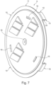
- Figs. 7 and 8 illustrate an enlarged perspective view of the cover plate as seen from above and from below. Reference numbers are inserted in order to more clearly indicate the elements already explained in connection with Figs. 3-6 .
- Fig. 9 illustrates a situation in which screw drivers 17 are inserted into the openings 16. When a bending force is exerted with the screw driver there will easily be a tilting of the cover plate which causes the breaking of the locking tabs along the weakening line.
- Figs. 10-11 illustrate embodiments for level means 19.
- the level means 19 comprises a housing 20 which is intended for being fixed in the hollow 18 in the cover plate 9.
- the level means comprise two perpendicularly arranged tubular spirit levels 21.
- Each of the levels comprises a bubble 22 and graduation 23 for visual indication of inclination.
- Fig. 11 illustrates a bull's eye spirit level 24.
- This bull's eye spirit level also comprises a bubble 22 and graduations 23 for visual indication of an inclination.
- Fig. 12 illustrates a straight tubular spirit level having a uniform diameter, however, having a curvature.
- Fig. 13 illustrates an embodiment with a straight tubular spirit level in which the central part is increased compared to the diameter of the outer ends of the tubular spirit level.
- Figs. 12 and 13 may be used in the level means 19 illustrated in Fig. 10 .
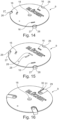
- Fig. 14 illustrates a cover plate 9 having openings 16 for a screw driver and a hollow 18 for containing a level means.
- This embodiment comprises first locking means in the form of tabs 26 which through weakening lines 27 are connected to the main part of the cover plate 9.
- the tabs will have a part arranged to engage under the flange of the drain.
- the tabs 26 When inserting screw driver in the opening 16 and exerting a force, the tabs 26 will break off by a breaking at the weakening line.
- the tab 26 will have a form as explained with the locking tabs 10 above.
- Fig. 15 corresponds to Fig. 14 .
- the cover plate according to Fig. 15 is provided with two rectilinear hollows 28 instead of the circular hollow 18 illustrated in Fig. 14 .
- the hollows 28 are provided directly in the cover plate 19 and are intended for containing tubular spirit level 21 of the type illustrated in Fig. 12 or 13 .
- Fig. 16 illustrates a further embodiment for a cover plate 9.
- the cover plate 9 is provided with with first locking means in form of tabs 29.
- the tabs will have a part arranged to engage under the flange of the drain.
- the tabs are provided with a pull eye 30 in which a finger can be inserted. Accordingly, the tab 29 can be denoted as a pull tab.
- the tab 29 is connected with the main part of the cover plate 9 through a weakening line 31.
- this cover plate may be removed without the use of a screw driver.
- Fig. 17 illustrates a cover plate 9 being provided with tabs 32.
- Tabs 32 are connected with the main part of cover plate 9 through a weakening line 33 which leaves an opening 34 between the tab 32 and the main part of the cover plate.
- the opening 34 can be used for inserting a screw driver.
- Fig. 18 illustrates the embodiment of Fig. 17 in which the screw driver 17 is inserted in the opening 34 in order to remove the tab 32 from the remainder of the cover plate.
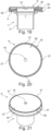
- Figs. 19-21 illustrate a further embodiment of a cover plate and a drain according to the present invention.
- the cover plate 9 is provided with a circular part 40 and a circumferential wall 35 connected with the circular part of the cover plate.
- the circumferential wall has at a distal end a narrow portion 39 which has a diameter which is smaller than the diameter of the circumferential wall arranged close to the circular part.
- the narrow portion 39 can enter into engagement under the flange 4.
- a clamping membrane 36 is arranged between the flange 4 and the circular part of the cover plate 9.
- the cover plate is provided with weakenings in form of incisions 37 arranged with regular distance around the circumference where the circular part is connected with the circumferential wall.
- the incisions make it easier that the circumferential wall is divided into different portions which can easily be bent away when removing the cover plate from the drain 1.
- the circumferential wall 35 is provided with a weakening line 38.
- the weakening line 38 makes it easier to damage the circumferential wall in order to remove it from the drain.
- the tabs provided in the cover plate will have the form corresponding to the locking tabs 10 disclosed in Fig. 4-6 .
- other embodiments for locking tabs are possible if they ensure a secure engagement with the drain 1 during installation.
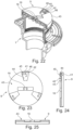
- Figs. 22-26 illustrate a further embodiment for a combination of a drain 1 and a cover plate 9.
- the first locking means is provided in form of a slit 41 which is provided in a recessed part 42 of the top surface 43 of the cover plate 9.
- the recessed part 42 is connected with the top surface 43 through wall parts 44.
- a wall opening 22 is visible.
- the wall opening 45 is in connection with the slit 41.
- the slit 41 is at a end portion provided with a chamfer 46 which allow a flat head screw 47 to sit in.
- the screw 47 is the screw which is used for connecting a grate 49 to the drain 1 by being screwed into threads 48 provided in the drain.
- the cover plate here will make use of elements, namely the screws 47 which are already present in the product for attaching the cover plate to the drain. There may be provided any number of screws.
- the cover plate Before placing the cover plate on the drain the screws 47 will not be tightened totally.
- the cover plate may be arranged on top of the grate 49 and rotated in such a way that the screws enter through the wall opening 45 and into the slit 41.
- the slit will have a part circular form in order to have a smooth rotation.
- the cover plate is affixed to the drain 1.
- the cover plate 9 As the cover plate 9 is in contact with the grating a secure orientation of the cover plate and the grating is established whereby the level means 19 arranged in the opening 18 is ready for use when aligning the drain.
- a protective sheet 50 having a form corresponding to the form of the surface of the cover plate 9 may be glued to the cover plate. Hereby it is secured that the cover plate may not unintentional be removed from the drain.
Landscapes
- Engineering & Computer Science (AREA)
- Health & Medical Sciences (AREA)
- Water Supply & Treatment (AREA)
- Public Health (AREA)
- Hydrology & Water Resources (AREA)
- Life Sciences & Earth Sciences (AREA)
- Radar, Positioning & Navigation (AREA)
- Remote Sensing (AREA)
- Physics & Mathematics (AREA)
- General Physics & Mathematics (AREA)
- Structural Engineering (AREA)
- Civil Engineering (AREA)
- Architecture (AREA)
- Sink And Installation For Waste Water (AREA)
Description
- The present invention relates to a combination of a cover plate and a drain, preferably a floor or roof drain, wherein the cover plate is provided with first locking means, and wherein the drain is provided with cooperating second locking means for releasable connection of the cover plate to the drain.
- Moreover the invention relates to the use of such combination.
- When mounting a drain in a floor or another plane surface it is necessary to adjust the inclination of the drain in order for a correct drainage of the surface in which the drain is arranged. Moreover, it is also necessary to protect the drain against damages which can occur on the drain during the installation and also to protect the drain against debris which may fall into an open drain, and prevent possible injury through trips and falls.
- In prior art an inclination of a drain has been adjusted by means of separate level tool. This is an instrument which is commonly known to indicate whether a surface is horizontal (level) or vertical (plumb). Level tools occur in different embodiments used by carpenters, bricklayers and other building trades' workers including workers installing drain systems in a surface to be drained which may be arranged inside or outside a building.
- When using a separate level tool there is a risk that the level tool has an extension which is insufficient or not suitable for a specific drain to be installed. Moreover, there is a risk that the drain may be affected after installation and aligning and this would cause the drain to be misaligned when the surrounding floor or covering at a later time is provided.
- When providing the surrounding floor or surrounding surface covering there might be a risk that debris fall into the drain as it has an uncovered upwardly opening. Moreover the upper side of the drain may be damaged when providing the surrounding floor or surrounding surface covering.
-
US 2005/138722 A1 discloses a combination of a drain and a temporary cover plate for use during installation of the drain. Locking means comprise a weakening getting damaged when the cover plate is removed from the drain. - Also
EP 1464768 discloses a combination of a drain with a cover plate in form of a grate The cover plate and drain is provided with cooperating locking means for releasable connection of the grate to the drain. The grate will not protect the drain against debris which may fall into the drain during installation of the drain. Moreover the grate cannot be used for ensuring correct levelling of the drain during installation. - In order to protect the drain it is suggested to provide a cover plate which is arranged over the open drain. In other solutions also a plastic film covering a grating in a drain bowl is used.
- The object of the present invention is to provide a combination of a cover plate and a drain in which the cover plate can be used to ensure a correct levelling and aligning of the drain during installation and which simultaneously protects the drain during installation and before the drain is taken into use.
- It is desired that the cover plate is arranged in such a way that the level is maintained in its position during and after installation in order to ensure the correct position and inclination of the drain after the installation procedures is finished and the surrounding floor or surrounding surface covering is provided.
- This object is obtained with a combination mentioned by way of introduction and which is peculiar in that the cover plate is provided with level means for determining the orientation of the cover plate and thereby also the drain in relation to a horizontal plane or a vertical, that the first locking means or the second locking means comprises a weakening arranged such that at least a part of the locking means is damaged when the cover plate is removed from the drain as the cover plate is a temporary cover plate for use during installation of the drain.
- According to an aspect the combination is used for a temporary protection of a drain during installation of the drain.
- According to another aspect the combination is used for installing and adjusting the inclination of the drain without need of separate level tools.
- With the combination of a cover plate and a drain comprising an interacting first and second locking means it is possible to attach the cover plate to a drain in a secure way. Hereby the correct position of the cover plate in relation to the drain is assured.
- With the correct mutual positioning of the cover plate and the drain a level arranged integral with the cover plate will continuously indicate the inclination of the drain as long as the cover plate is connected to the drain.
- When the cover plate is arranged on the drain it is ensured that there is a secure contact which closes the upwardly open part of the drain. The open part of the drain will be tightly closed by the cover plate when the first and second locking means are in engagement with each other.
- The drain and the cover plate can have any form. Preferably they will have a rotational symmetry, such as a cylindrical shape. However, they may also have other shapes such as oval or polygonal, such a triangular, rectangular, pentagonal, hexagonal or octagonal.
- After installation of the drain is completed the drain shall be opened. This is established by disengaging the locking means.
- The locking means are preferably arranged such that at least a part of the locking means is damaged when the cover plate is removed.
- When the locking means is damaged it is ensured that the cover plate will not be attached to the drain afterwards. This is important as the cover plate may be arranged in incorrect position and thereby can give an incorrect indication of the inclination of the drain. This may also incur risk that debris can fall into the drain with an incorrect positioned cover plate.
- The opening of the drain after installation is easy to conduct due to the weakening arranged in the first or second locking means.
- The weakening will provide a damage of the locking means. The result is that the cover plate cannot be reused and mounted on another drain. This will ensure that a damaged cover plate cannot be arranged on a drain in an incorrect position.
- The level means used can be of different types. It is important that they have a sensitivity which is adapted to the extension of the cover plate. The sensitivity of a level is given as a change of angle or gradient which is required to move a bubble in a given distance inside a tube.
- The level can be arranged with a slightly curved glass tube with constant inner diameter or be arranged with an un-curved barrel-shaped tube with a slightly larger diameter in its middle.
- It is also possible that the level is a bull's eye spirit level.
- According to a further aspect the combination is peculiar in that the level means is chosen between a bull's eye spirit level and a combination of two perpendicularly arranged tubular spirit levels.
- As mentioned different types of levels may be used. However, when using the straight tubular spirit level it is important that there are used two tubular spirit levels which are arranged perpendicular to each other. Hereby it is possible to have an adjustment of the inclination of the drain in any directions and not only in one direction indicated with only one tubular spirit level.
- The use of a bull's eye spirit level will also ensure the possibility of adjusting the inclination in any direction in a 360° orientation.
- According to a further aspect the combination is peculiar in that the level means comprises a bubble housing being provided with graduations for visual indication of an inclination.
- The sensitivity is important. The sensitivity of a level is given as the change of angle required to move a bubble by a unit distance. If the bubble housing is provided with graduations indicating the unit distances then it is possible to have a visual indication of a desired tilt needed for a given drain. Such tilt can be orientated in any direction. Hereby the cover plate makes it possible to adjust the tilt of a drain in a floor or a surface outside a building.
- According to a further aspect the combination is peculiar in that the cover plate is made of plastic, preferably polypropylene, and that the level means is embedded into the cover plate, preferably in a plane surface thereof.
- When the cover plate is made of plastic it is possible to mold the plastic with the level means embedded into the cover plate. Normally the cover plate will be a flat plate having a plane surface. Therefore in such situation the level means are embedded into the plane surface.
- The level means may also be mounted in the surface of the cover plate with an extension above the surface of the cover plate. However, for protecting the level it is preferred that the level is embedded into the surface of the cover plate.
- The level may be arranged in any part of the cover plate. However, it is preferred that the level is provided in a central part of the cover plate.
- The level is made as an integral part of the cover plate. It is preferred that the level is provided in the cover plate during the manufacture thereof, however it may be mounted in the cover plate after the cover plate has been manufactured. In both situations it is important that the level is secured into the cover plate in order to be an integral part thereof. This can be established either by shrinking, gluing or with other fixation means.
- According to a further aspect the combination is peculiar in that the weakening is a weakening line, which is arranged to ensure that at least a part of the first locking means breaks off when the cover plate is removed.
- When removing the cover plate it is necessary that at least a part of the locking means breaks of. This is ensured when a weakening line is arranged in the locking means or is arranged between the locking means and the cover plate.
- According to a further aspect the combination is peculiar in that the the first locking means comprises locking tabs arranged along a circumferential edge of the cover plate and that the second locking means comprises a flange or a groove in the drain.
- Most drain will be arranged with a flange in the upper part along an upwardly opening. Therefore it is preferred that the first locking means comprises locking tabs arranged along a circumferential edge of the cover plate. The circumferential edge of the cover plate will be adapted to the actual form of the upper part of the drain. When the drain is provided with a flange the locking means can be tabs which are arranged with an arrow-shaped or toothed front part which can be engaged beneath the flange.
- The tabs may be flexible in such a way that they can be pressed down and the arrow-shaped front part of the tabs can enter into engagement with the flange. When the cover plate shall be removed then the weakening line causes a damaging and the tabs will break off when the plate is removed.
- Instead of having an engagement beneath a flange it is also possible to have an engagement in a groove or holes provided in the drain and in which the locking tabs may enter into engagement.
- According to a further aspect the combination is peculiar in that the cover plate comprises at least one opening in which a tool can be inserted in order to tilt or rotate the cover plate. Said opening is provided in a top surface of the cover plate.
- According to a further aspect the combination is peculiar in that the tilting or rotation of the cover plate causes a damaging of locking means by a tilting or rotational movement of the cover plate for removing the cover plate from the drain.
- When the cover plate is arranged on the drain arranged in the surrounding floor or ground a covering is established. The cover plate can be removed in order to place a grating in the drain or in order to connect the drain with pipework in the space above the surface in which the drain is positioned. As the cover plate comprises an opening in a top surface a tool can be inserted into the opening order to tilt or rotate the cover plate to remove it from the drain.
- If a rotation is established, the locking means can be provided in the form by bayonet-coupling having toothings or projections which allow a rotation only in one direction and which causes a breaking off of the tabs provided with toothings or projections when rotation is effected in the other direction. If the tabs are used to engage in a groove in a flange or beneath a flange then a tilting will cause the damaging of the locking tabs.
- According to a further aspect the combination is peculiar in that the opening is the cover plate is a slit in which a screw driver may be inserted.
- Seeing that most workers always will have a screw driver in their tool box it is convenient that the opening is one or more slits in which one or more screw drivers are inserted. The bending force exerted with the screw driver will easily cause a tilting of the cover plate which causes the damaging of the locking means.
- Alternatively it is possible to provide a ring pull in the cover plate. Hereby the cover plate can be removed like opening a can of sardines. In this situation the locking means can be provided in form of a weakening line dividing the cover plate in a central portion and a circumferential portion which breaks off and is removed when pulling the ring pull. In this embodiment the workers do not need a tool for removing he cover plate.
- According to a further aspect the combination is peculiar in that the drain is a drain bowl, a drain stub or other drain unit arranged for mounting in a floor or other horizontal surface from which liquid shall be drained.
- The drain can have any form or be of any type. It may be a bowl or a stub or another drain unit which is arranged in a floor or any other surface from which liquid shall be drained. The advantages of the level means being integral with the cover plate will be usable in all types of drain.
- Even though a drain would normally be arranged in a horizontal surface it is also possible to have vertical surfaces in which drains are arranged. Accordingly, the cover plate will also be usable for covering drains arranged in vertical or oblique surfaces.
- E.g. it is known that drains are arranged with an angle and provided a floor and a wall. A cover plate can also be used in such drain.
- It is explained that the cover plate will have a hole for breaking away by means of a screwdriver. However, it is also possible to provide holes which usable with other special tools. Accordingly, the hole can be arranged in such a way that it can be used together with an allen key for rotating the cover plate in order to break the tabs.
- The cover plate has especially been explained in connection with security during construction of a house. However, a cover plate can also be used for security application, e.g. in prisons or psychiatric hospitals. Hereby it is impossible for people to hide items in the drain without the possibility that this would be observed by guards.
- According to a further aspect the combination is peculiar in that the cover plate is made by vacuum forming and comprising a circular part and a circumferential wall connected to the circular part and having a narrow portion at a distal end of the circumferential wall.
- The vacuum formed cover plate is simple to produce. The tool manufacturing time is limited and accordingly it is possible to produce different tools within a few days at low costs.
- In the vacuum formed cover plate the circumferential wall will have a narrow portion which constitutes the first locking means. The narrow portion at the distal end of the circumferential wall is intended to engagement under the flange hereby securing the cover plate to the drain.
- When mounting the cover plate to the drain a clamping membrane can be arranged between the circular part of the cover plate and the flange.
- According to a further aspect the combination is peculiar in that at least one perforation is provided in the circumferential wall.
- The perforation which is provided in the circumferential wall will ensure that the wall is damaged whereby it is possible to remove the cover plate from the drain.
- It is preferred that the cover plate is provided with incisions at the transition between the circular part and the circumferential wall. The incisions may be used for insertion of tools to break away the circumferential wall. Furthermore, the incisions will make it easier to remove the cover plate from the flange of the drain as the narrow portion can be bent outwardly when lifting the cover plate away from the drain.
- According to a further aspect the combination is peculiar in that the first locking means, is at least one slit which is provided in a recessed part of the surface of the cover plate, which recessed part via wall parts is connected to the surface of the cover plate, that the wall parts are provide with a wall opening connected with the slit, that the cooperating second locking means comprises a screw passing through a corresponding slit for connecting the cover plate to the drain, that the screw is screwed into a thread provided in the drain and that the slit and wall opening is arranged such that after loosening the screw a rotation of the cover plate brings the screw through the wall opening for releasing the connection of the cover plate to the drain.
- With this embodiment there is no part of the locking means which are damaged when the cover plate is removed. When the cover plate is to be arranged on the drain the screws used for attaching the grate to the drain is loosened and hereby it is possible to place the cover plate on top of the drain and align the screws with the corresponding slits. Then the rotation of the cover plate will bring the screws into the slit. At the end portion of the slit there is preferably provided a chamfer to allow a flat head screw to sit in. This will ensure a correct positioning of the cover plate on the drain.
- After tightening the screws the cover plate will be placed correctly on top of the drain.
- After use the cover plate should be removed. This is done by loosening the screws. When the screws are loosened the cover plate may be turned in the way opposite the direction used for placing the cover plate on the drain. Hereby the screw will move through the slit and could go out through the wall opening.
- The slit will preferably open out into the wall opening whereby there is an open connection which allows the screw head to pass through the wall opening. Hereby it is possible to lift the cover plate free of the drain.
- The cover plate may voluntarily be provided with a protective sheet having a form corresponding to the surface of the cover plate. The protective sheet will ensure that matters cannot enter into the recessed parts of the top surface of the cover plate.
- Moreover, the protective sheet may also be used to indicate whether a tampering has been effected after the cover plate has been arranged on the drain. The protective sheet may be glued to the surface of the cover plate after the cover plate is arranged on a drain. Hereby it is only possible to have access to the screws by removing the protective sheet. Hereby the removal will be an indication that the cover plate has been removed earlier and thereby there is a risk for a misaligning of the cover plate. Even though there is no damaging of the locking means when removing the cover plate, then a damaging of the protective sheet will give a security as an unbroken protective sheet is an indication that the cover plate is arranged correct on the drain.
- The combination according to the invention may be used for a temporary protection of a drain during installation of the drain. The combination according to the invention may also be used for installing and adjusting the inclination of the drain without need of separate level tools.
- An embodiment to the invention will be described by way of example only and with reference to the accompanying drawings, in which
- Fig. 1
- shows a section through an embodiment of a drain,
- Fig. 2
- shows the drain of
Fig. 1 as seen from above, - Fig. 3
- shows an embodiment of a drain seen from above, and intended for use in combination with the drain of
Fig. 1 - Fig. 4
- illustrates a view of the cover plate of
Fig. 3 as seen from the side, - Fig. 5
- shows a cross section IV-IV in
Fig. 3 , - Fig. 6
- illustrates an enlarged detail of the cross section of
Fig. 5 , - Fig. 7
- illustrates a perspective view of the cover plate illustrated in
Figs. 3-6 as seen from above - Fig. 8
- illustrates a perspective view of the cover plate illustrated in
Fig. 7 as seen from below, - Fig. 9
- illustrates an initial step in removing the cover plate of
Figs. 3-8 from a drain according toFigs. 1 and 2 , - Fig. 10
- shows an embodiment for level means to be used in the cover plate,
- Fig. 11
- shows a further embodiment for level means to be used in the cover plate,
- Fig. 12
- shows an embodiment of a bubble housing being a part of the level means,
- Fig. 13
- shows a further embodiment of a bubble housing being a part of the level means,
- Fig. 14
- shows a further embodiment for a cover plate,
- Fig. 15
- shows a further embodiment of a cover plate,
- Fig. 16
- shows a further embodiment for a cover plate,
- Fig. 17
- shows a further embodiment for a cover plate,
- Fig. 18
- corresponds to
Fig. 9 and illustrates an initial step in removing the cover plate ofFig. 17 from a drain according toFigs. 1 and 2 , - Figs.
- 19-21 illustrate a further embodiment of a cover plate and a drain according to the present invention,
- Fig. 22
- illustrates a cross sectional perspective view of a further embodiment of a cover plate and a drain, according to the present invention,
- Fig. 23
- illustrates a plan view of the cover plate illustrated in
Fig. 22 , - Fig. 24
- illustrates a cross section through the cover plate illustrated in
Fig. 22 , - Fig. 25
- illustrates a further cross section through the cover plate illustrated in
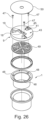
Fig. 22 , and - Fig. 26
- illustrates an exploded view of the cover plate and the drain illustrated in
Fig. 22 . - In the following text the figures will be described one by one and the different parts and positions seen in the figures will be numbered with the same numbers in the different figures. Not all parts and positions indicated in a specific figure will be discussed in connection with that figure.
-
Fig. 1 illustrates adrain 1 comprising a lower part 2, which is intended for connection with piping below thesurface 3 in which the drain 2 is arranged. The drain comprises anupper end 4 having aflange 5 which is preferably a circumferential flange. The drain comprises a hole 6 which is intended for use with a screw used to fasten a grating (not illustrated) which is used for cover anupwardly opening 7 of thedrain 1. - The
flange 5 has athickness 8 which is adjusted to the specific cover plate as explained later. - It is noted that there will always be an additional layer on top of a first pour which are made by the main contractor. The finish of a floor will be effected by a floor contractor.
- Therefore a space will exist between the drain and the floor made by the first contractor and the space makes it possible to provide tabs for a cover plate as explained later. The space will be covered by the floor contractor.
- When the floor contractor has finished the work the tabs of the cover plate covering the drain will be embedded in the finishing layer of the floor.
- The drain can be produced from different materials. It can e.g. be made from plastic, metal cast iron, concrete, clay or other materials which are found suitable for manufacture of a drain.
- In
Fig. 2 it is seen that theflange 5 is a circular flange. However, it might have other configuration and it do not necessarily been to be acircumferential flange 5. -
Fig. 3 illustrates acover plate 9 which is used for covering theopening 7 of thedrain 1. Thecover plate 9 is provided with first locking means which are provided in form of lockingtabs 10 which are arranged along acircumferential edge 11 of thecover plate 9. The lockingtabs 10 cooperate with second locking means in form of theedge area 12 of theflange 5. As more clearly illustrated inFigs. 4-6 one can see that the lockingtabs 10 comprise aleg portion 25 connecting a wedge shapedouter end 13 with theplate portion 14 of thecover plate 9. Theleg portion 25 is flexible and thereby provides the possibility that the lockingtabs 10 may be pressed down over theflange 5 whereby theouter end 13 will enter into engagement with theedge area 12 at the downwardly orientated surface of theflange 5. Hereby the cover plate will be connected to the drain. - As most clearly illustrated in
Fig. 6 the cover plate comprises a weakeningline 15 connecting thelocking tab 10 with theplate portion 14. Accordingly, the connection between the cover plate and drain is releasable, however, the lockingtabs 10 will break off when the cover plate is removed from the drain as thelower end 13 will have engagement with the downwardly orientated surface of theflange 5 and therefore a breaking will occur along the weakeningline 15. - The
cover plate 9 is provided withopenings 16. Eachopening 16 may be slit-formed and intended for the engagement with ascrew driver 17 as illustrated inFig. 9 . The screw driver is used for removing thecover plate 9 from thedrain 1. - The cover plate comprises a hollow 18. The hollow 18 is intended to contain a level means 19 (see description below) which is intended for determining the orientation of the cover plate and thereby also the orientation of the
drain 1 in relation to a horizontal plane or a vertical. The level means 19 may be fixed in the hollow 18 in different ways. The fixation is intended to be fixed and not removable in order to secure that the level means always will have a fixed orientation in relation to thecover plate 9. - The level means may be cast into the cover plate during production of the cover plate or may be attached in the hollow by gluing after the production of the cover plate with the hollow 18.
-
Figs. 7 and8 illustrate an enlarged perspective view of the cover plate as seen from above and from below. Reference numbers are inserted in order to more clearly indicate the elements already explained in connection withFigs. 3-6 . -
Fig. 9 illustrates a situation in which screwdrivers 17 are inserted into theopenings 16. When a bending force is exerted with the screw driver there will easily be a tilting of the cover plate which causes the breaking of the locking tabs along the weakening line. -
Figs. 10-11 illustrate embodiments for level means 19. The level means 19 comprises ahousing 20 which is intended for being fixed in the hollow 18 in thecover plate 9. - In
Fig. 10 the level means comprise two perpendicularly arrangedtubular spirit levels 21. Each of the levels comprises abubble 22 andgraduation 23 for visual indication of inclination. -
Fig. 11 illustrates a bull'seye spirit level 24. This bull's eye spirit level also comprises abubble 22 andgraduations 23 for visual indication of an inclination. -
Fig. 12 illustrates a straight tubular spirit level having a uniform diameter, however, having a curvature. -
Fig. 13 illustrates an embodiment with a straight tubular spirit level in which the central part is increased compared to the diameter of the outer ends of the tubular spirit level. - The embodiments of
Figs. 12 and 13 may be used in the level means 19 illustrated inFig. 10 . -
Fig. 14 illustrates acover plate 9 havingopenings 16 for a screw driver and a hollow 18 for containing a level means. - This embodiment comprises first locking means in the form of
tabs 26 which throughweakening lines 27 are connected to the main part of thecover plate 9. The tabs will have a part arranged to engage under the flange of the drain. - When inserting screw driver in the
opening 16 and exerting a force, thetabs 26 will break off by a breaking at the weakening line. Thetab 26 will have a form as explained with the lockingtabs 10 above. -
Fig. 15 corresponds toFig. 14 . The cover plate according toFig. 15 is provided with tworectilinear hollows 28 instead of the circular hollow 18 illustrated inFig. 14 . Thehollows 28 are provided directly in thecover plate 19 and are intended for containingtubular spirit level 21 of the type illustrated inFig. 12 or 13 . -
Fig. 16 illustrates a further embodiment for acover plate 9. Thecover plate 9 is provided with with first locking means in form oftabs 29. The tabs will have a part arranged to engage under the flange of the drain. The tabs are provided with apull eye 30 in which a finger can be inserted. Accordingly, thetab 29 can be denoted as a pull tab. Thetab 29 is connected with the main part of thecover plate 9 through a weakeningline 31. - When inserting a finger in the
pull eye 30 it is possible to remove thetab 29. - Accordingly, this cover plate may be removed without the use of a screw driver.
-
Fig. 17 illustrates acover plate 9 being provided withtabs 32.Tabs 32 are connected with the main part ofcover plate 9 through a weakeningline 33 which leaves anopening 34 between thetab 32 and the main part of the cover plate. Theopening 34 can be used for inserting a screw driver. -
Fig. 18 illustrates the embodiment ofFig. 17 in which thescrew driver 17 is inserted in theopening 34 in order to remove thetab 32 from the remainder of the cover plate.Figs. 19-21 illustrate a further embodiment of a cover plate and a drain according to the present invention. - In the cross section in
Fig. 19 one can see that thecover plate 9 is provided with acircular part 40 and acircumferential wall 35 connected with the circular part of the cover plate. - The circumferential wall has at a distal end a
narrow portion 39 which has a diameter which is smaller than the diameter of the circumferential wall arranged close to the circular part. Hereby thenarrow portion 39 can enter into engagement under theflange 4. In the embodiment illustrated a clampingmembrane 36 is arranged between theflange 4 and the circular part of thecover plate 9. - In the top view illustrated in
Fig. 20 one can see that the cover plate is provided with weakenings in form ofincisions 37 arranged with regular distance around the circumference where the circular part is connected with the circumferential wall. The incisions make it easier that the circumferential wall is divided into different portions which can easily be bent away when removing the cover plate from thedrain 1. - From the perspective view illustrated in
Fig. 21 one can see that thecircumferential wall 35 is provided with a weakeningline 38. The weakeningline 38 makes it easier to damage the circumferential wall in order to remove it from the drain. - In the above embodiments the tabs provided in the cover plate will have the form corresponding to the locking
tabs 10 disclosed inFig. 4-6 . However, other embodiments for locking tabs are possible if they ensure a secure engagement with thedrain 1 during installation. -
Figs. 22-26 illustrate a further embodiment for a combination of adrain 1 and acover plate 9. - In these Figures the first locking means is provided in form of a
slit 41 which is provided in a recessedpart 42 of thetop surface 43 of thecover plate 9. The recessedpart 42 is connected with thetop surface 43 throughwall parts 44. - Especially from
Fig. 22 awall opening 22 is visible. Thewall opening 45 is in connection with theslit 41. One can say that theslit 41 will open into the wall opening. - The
slit 41 is at a end portion provided with achamfer 46 which allow aflat head screw 47 to sit in. Thescrew 47 is the screw which is used for connecting agrate 49 to thedrain 1 by being screwed intothreads 48 provided in the drain. - Accordingly, the cover plate here will make use of elements, namely the
screws 47 which are already present in the product for attaching the cover plate to the drain. There may be provided any number of screws. - Before placing the cover plate on the drain the
screws 47 will not be tightened totally. Hereby the cover plate may be arranged on top of thegrate 49 and rotated in such a way that the screws enter through thewall opening 45 and into theslit 41. The slit will have a part circular form in order to have a smooth rotation. When the screws are aligned with thechamfer 46 they will be tightened. Hereby the cover plate is affixed to thedrain 1. As thecover plate 9 is in contact with the grating a secure orientation of the cover plate and the grating is established whereby the level means 19 arranged in theopening 18 is ready for use when aligning the drain. - After the cover plate is arranged a
protective sheet 50 having a form corresponding to the form of the surface of thecover plate 9 may be glued to the cover plate. Hereby it is secured that the cover plate may not unintentional be removed from the drain. - When the cover plate shall be removed from the grating the
protective sheet 50 is broken or torn away. Hereby it is possible to loosen thescrews 47 and effect a rotation of the cover plate whereby the screws pass through the slit and enter through thewall opening 45. Hereby it is possible to remove thecover plate 9 from thedrain 1. -
- 1
- drain
- 2
- lower part
- 3
- surface
- 4
- upper end
- 5
- flange
- 6
- hole
- 7
- opening
- 8
- thickness
- 9
- cover plate
- 10
- locking tabs
- 11
- circumferential edge
- 12
- edge area
- 13
- outer end
- 14
- plate portion
- 15
- weakening line
- 16
- opening
- 17
- screw driver
- 18
- hollow
- 19
- level means
- 20
- housing
- 21
- tubular spirit level
- 22
- bubble
- 23
- graduation
- 24
- bull's eye spirit level
- 25
- leg portion
- 26
- tab
- 27
- weakening line
- 28
- hollow
- 29
- tab
- 30
- pull eye
- 31
- weakening line
- 32
- tab
- 33
- weakening line
- 34
- opening
- 35
- circumferential wall
- 36
- clamping membrane
- 37
- incision
- 38
- weakening line
- 39
- narrow portion
- 40
- circular part
- 41
- slit
- 42
- recessed part
- 43
- top surface of cover plate
- 44
- wall parts
- 45
- wall opening
- 46
- chamfer - in slit
- 47
- screw
- 48
- thread
- 49
- grate
- 50
- protective sheet
Claims (15)
- A combination of a cover plate (9) and a drain (1), preferably a floor or roof drain, wherein the cover plate is provided with first locking means (10,26,29,32,39,41), and wherein the drain is provided with cooperating second locking means (12,47,50) for releasable connection of the cover plate to the drain, wherein the first locking means or the second locking means comprises a weakening (15,27,33,37,38) arranged such that at least a part of the locking means (10,26,29,32,39) is damaged when the cover plate (9) is removed from the drain (1) as the cover plate is a temporary cover plate for use during installation of the drain, characterised in that the cover plate is provided with level means (19,21,24) for determining the orientation of the cover plate and thereby also the drain in relation to a horizontal plane or a vertical.
- Combination according to claim 1, characterised in that the level means (19,21,24) is chosen between a bull's eye spirit level (24) and a combination of two perpendicularly arranged tubular spirit levels (21).
- Combination according to claim 2, characterised in that the level means comprises a bubble housing being provided with graduations (23) for visual indication of an inclination.
- Combination according to any of the preceding claims, characterised in that the cover plate (9) is made of plastic, preferably polypropylene, and that the level means (19,21,24) is embedded into the cover plate, preferably in a plane surface thereof.
- Combination according to any of the preceding claims, characterised in that the weakening (15,27,33,37,38) is a weakening line (15,27,33,38) , which is arranged to ensure that at least a part of the first locking means (10,26,29,32,39) breaks off when the cover plate is removed.
- Combination according to any of the preceding claims, characterised in that the the first locking means (10,26,29,32,39) comprises locking tabs (10,26,29,32) arranged along a circumferential edge (11) of the cover plate (9) and that the second locking means comprises a flange (5) or a groove in the drain.
- Combination according to any of the preceding claims, characterised in that the cover plate comprises at least one opening (16) in which a tool (17) can be inserted in order to tilt or rotate the cover plate.
- Combination according to claim 7, characterised in that the tilting or rotation of the cover plate causes the damaging of said at least a part of the locking means (10, 26, 29, 32, 39) by a tilting or rotational movement of the cover plate for removing the cover plate from the drain.
- Combination according to claim 7 or 8, characterised in that the opening in the cover plate is a slit (16) in which a screw driver (17) may be inserted.
- Combination according to any of the preceding claims, characterised in that the drain (1) is a drain bowl, a drain stub or other drain unit arranged for mounting in a floor or other horizontal surface (3) from which liquid shall be drained.
- Combination according to any of the claims 1-4, characterised in that the cover plate (9) is made by vacuum forming and comprising a circular part and a circumferential wall (35) connected to the circular part (40) and having a narrow portion (39) at a distal end of the circumferential wall.
- Combination according to claim 11, characterised in that at least one perforation (37,38) is provided in the circumferential wall (35).
- Combination according to any of the claims 1, 2, 3, 4, 10 or 11, characterised in that the first locking means, is at least one slit (41) which is provided in a recessed part (42) of the surface (43) of the cover plate (9), which recessed part via wall parts (44) is connected to the surface (43) of the cover plate, that the wall parts (44) are provided with a wall opening (45) connected with the slit (41), that the cooperating second locking means comprises a screw (47) passing through a corresponding slit (41) for connecting the cover plate to the drain (1), that the screw is screwed into a thread (48) provided in the drain and that the slit and wall opening is arranged such that after loosening the screw a rotation of the cover plate brings the screw through the wall opening for releasing the connection of the cover plate to the drain.
- Use of a combination according to any of the preceding claims for a temporary protection of a drain during installation of the drain.
- Use of a combination according to any of the claims 1-13 for installing and adjusting the inclination of the drain without need of separate level tools.
Applications Claiming Priority (2)
| Application Number | Priority Date | Filing Date | Title |
|---|---|---|---|
| DKPA201870126A DK179869B1 (en) | 2018-02-26 | 2018-02-26 | Combination of a cover plate and a drain and use of such combination |
| PCT/DK2019/050074 WO2019161874A1 (en) | 2018-02-26 | 2019-02-26 | Combination of a cover plate and a drain and use of such combination |
Publications (3)
| Publication Number | Publication Date |
|---|---|
| EP3759287A1 EP3759287A1 (en) | 2021-01-06 |
| EP3759287A4 EP3759287A4 (en) | 2021-12-08 |
| EP3759287B1 true EP3759287B1 (en) | 2023-06-07 |
Family
ID=67686876
Family Applications (1)
| Application Number | Title | Priority Date | Filing Date |
|---|---|---|---|
| EP19757003.9A Active EP3759287B1 (en) | 2018-02-26 | 2019-02-26 | Combination of a cover plate and a drain and use of such combination |
Country Status (5)
| Country | Link |
|---|---|
| US (1) | US11384523B2 (en) |
| EP (1) | EP3759287B1 (en) |
| CN (1) | CN213741474U (en) |
| DK (1) | DK179869B1 (en) |
| WO (1) | WO2019161874A1 (en) |
Cited By (1)
| Publication number | Priority date | Publication date | Assignee | Title |
|---|---|---|---|---|
| US20220298772A1 (en) * | 2018-02-26 | 2022-09-22 | Blucher Metal A/S | Fast installation cap and drain |
Families Citing this family (9)
| Publication number | Priority date | Publication date | Assignee | Title |
|---|---|---|---|---|
| US10711447B2 (en) * | 2016-09-12 | 2020-07-14 | Zurn Industries, Llc | Adjustable floor drain and method of installation |
| US11078658B2 (en) * | 2018-04-17 | 2021-08-03 | Zurn Industries, Llc | Cover assembly and methods |
| USD940081S1 (en) * | 2019-10-04 | 2022-01-04 | Arlington Industries, Inc. | Flanged conduit cap with coupling |
| USD1067200S1 (en) | 2020-12-18 | 2025-03-18 | Hitachi Energy Ltd | Flange for fastening, supporting, or mounting |
| JP7735141B2 (en) * | 2021-09-29 | 2025-09-08 | 積水化学工業株式会社 | Drain outlet protection equipment and roof drain installation method |
| CN114197616B (en) * | 2021-12-08 | 2022-12-06 | 无锡市第五市政建设工程有限责任公司 | Municipal drainage is with rainwater well that has filtering capability and be convenient for flood discharge |
| US11946241B2 (en) * | 2022-02-04 | 2024-04-02 | Oatey Co. | Drain assemblies, and related kits and methods |
| US12371892B2 (en) | 2022-03-31 | 2025-07-29 | Oatey Co. | Drain assemblies, and related kits and methods |
| CN115031686B (en) * | 2022-06-06 | 2024-08-02 | 新疆卓越工程项目管理有限公司 | Intelligent automatic level gauge for building supervision site |
Family Cites Families (25)
| Publication number | Priority date | Publication date | Assignee | Title |
|---|---|---|---|---|
| US1812583A (en) * | 1930-04-09 | 1931-06-30 | Cavalieri Silvestro | House drain fitting |
| US3445973A (en) * | 1967-02-01 | 1969-05-27 | Robert E Stone | Removable cover for drain fixture |
| US5265752A (en) | 1991-09-26 | 1993-11-30 | Alliance Plastics | Flange protector having integral connectors |
| US5244040A (en) * | 1992-03-18 | 1993-09-14 | Texaco Inc. | Method and apparatus to determine wellhead level |
| DE9413695U1 (en) | 1994-08-25 | 1994-10-27 | Schrempp, Siegfried, 77793 Gutach | Spirit level for the installation of commercially available electrical installation boxes and box combinations |
| US6076559A (en) | 1997-04-16 | 2000-06-20 | Gregory N. Castillo | Protective cover for plumbing fixtures |
| US5921282A (en) * | 1997-04-16 | 1999-07-13 | Tci Products | Protective cover for plumbing fixtures |
| US6568021B1 (en) * | 2000-02-10 | 2003-05-27 | George W. Wood | Trowel with levels |
| US6668417B1 (en) * | 2000-03-17 | 2003-12-30 | Anthony D. Slattery | Handle systems for hand floats |
| DK175299B1 (en) | 2003-04-01 | 2004-08-16 | Bluecher Metal Aps | Floor drainage |
| KR100569048B1 (en) | 2003-06-03 | 2006-04-12 | 최해권 | Drainage gutter with temporary drainage hole and floor construction method using drainage gutter |
| US7055184B2 (en) * | 2003-12-30 | 2006-06-06 | Ips Corporation | Closet flange with knockout retainer |
| US20070034577A1 (en) * | 2005-08-10 | 2007-02-15 | Bestweld Inc. | Self-locking grate for deck drain fitting |
| US7735512B1 (en) * | 2005-08-12 | 2010-06-15 | Sioux Chief Mfg. Co., Inc. | Floor drain installation system |
| US20070246116A1 (en) * | 2006-04-21 | 2007-10-25 | Peak B David | Drainage pipe slope measuring device |
| NL1033353C2 (en) * | 2007-02-07 | 2008-08-11 | Wavin Bv | Pot element. |
| US8671991B2 (en) | 2009-11-30 | 2014-03-18 | Protective Industries, Inc. | Flange protector and lug |
| US8443844B2 (en) | 2009-11-30 | 2013-05-21 | Protective Industries, Inc. | Flange protector |
| US10041242B2 (en) * | 2011-03-21 | 2018-08-07 | Erika Yssel | Toilet flange assembly with cover |
| US10370841B2 (en) | 2014-07-11 | 2019-08-06 | The Drain Company, Llc | Drain and drain leveling mechanism |
| PL3031990T3 (en) | 2014-12-11 | 2020-09-21 | Hl Hutterer & Lechner Gmbh | Floor drain |
| US9651372B1 (en) * | 2015-01-08 | 2017-05-16 | Jose Antonio Lopez | Piping leveling systems |
| US9869081B1 (en) * | 2016-08-05 | 2018-01-16 | John Parde, III | Toilet flange cover system |
| US10711447B2 (en) * | 2016-09-12 | 2020-07-14 | Zurn Industries, Llc | Adjustable floor drain and method of installation |
| US11078658B2 (en) * | 2018-04-17 | 2021-08-03 | Zurn Industries, Llc | Cover assembly and methods |
-
2018
- 2018-02-26 DK DKPA201870126A patent/DK179869B1/en active IP Right Grant
-
2019
- 2019-02-26 WO PCT/DK2019/050074 patent/WO2019161874A1/en not_active Ceased
- 2019-02-26 US US16/975,617 patent/US11384523B2/en active Active
- 2019-02-26 CN CN201990000516.2U patent/CN213741474U/en active Active
- 2019-02-26 EP EP19757003.9A patent/EP3759287B1/en active Active
Cited By (2)
| Publication number | Priority date | Publication date | Assignee | Title |
|---|---|---|---|---|
| US20220298772A1 (en) * | 2018-02-26 | 2022-09-22 | Blucher Metal A/S | Fast installation cap and drain |
| US12460402B2 (en) * | 2018-02-26 | 2025-11-04 | Blucher Metal A/S | Fast installation cap and drain |
Also Published As
| Publication number | Publication date |
|---|---|
| US11384523B2 (en) | 2022-07-12 |
| US20210010254A1 (en) | 2021-01-14 |
| EP3759287A4 (en) | 2021-12-08 |
| WO2019161874A1 (en) | 2019-08-29 |
| EP3759287A1 (en) | 2021-01-06 |
| DK201870126A1 (en) | 2019-08-07 |
| CN213741474U (en) | 2021-07-20 |
| DK179869B1 (en) | 2019-08-07 |
Similar Documents
| Publication | Publication Date | Title |
|---|---|---|
| EP3759287B1 (en) | Combination of a cover plate and a drain and use of such combination | |
| US11008728B2 (en) | Manhole device | |
| CA2626577C (en) | Curb box cover assembly | |
| US7931122B2 (en) | Manhole construction safety and work platform device | |
| US9074377B2 (en) | Tile installation guide and related method | |
| US12460402B2 (en) | Fast installation cap and drain | |
| US9151038B2 (en) | Anchor bolt devices and operating methods for residential and commercial structures | |
| CA2441528A1 (en) | Tolerant mounting apparatus | |
| WO1994004328A1 (en) | Adjustable apparatus for forming voids in concrete | |
| US7464507B2 (en) | Devices and methods for protecting exposed pipe ends during construction | |
| US20190063032A1 (en) | Meter cover | |
| AU2007250511A1 (en) | Building brace | |
| US11613866B1 (en) | Retainer for closure device | |
| AU2023100047B4 (en) | Attachment for positioning cast-in concrete anchors | |
| WO2014036602A1 (en) | Plumber's level | |
| JP2019120060A (en) | Jig, level display device, and auxiliary device | |
| KR101702848B1 (en) | Multidirectional indication nail for underground pipe | |
| GB2574070A (en) | Manhole device | |
| AU2021273625A1 (en) | Attachment for positioning cast-in concrete anchors | |
| WO2023283696A1 (en) | Attachment for positioning cast-in-place anchor bolts, supporting a setdown and associated methods | |
| GB2314871A (en) | Cover for sewage trap | |
| JP3141267B2 (en) | Box cover installation method for wiring and piping and box cover | |
| JP6359728B1 (en) | Hole measurement method | |
| NZ786529A (en) | Post bracket and blank for forming same | |
| JP4089497B2 (en) | Floor panel support device |
Legal Events
| Date | Code | Title | Description |
|---|---|---|---|
| STAA | Information on the status of an ep patent application or granted ep patent |
Free format text: STATUS: THE INTERNATIONAL PUBLICATION HAS BEEN MADE |
|
| PUAI | Public reference made under article 153(3) epc to a published international application that has entered the european phase |
Free format text: ORIGINAL CODE: 0009012 |
|
| STAA | Information on the status of an ep patent application or granted ep patent |
Free format text: STATUS: REQUEST FOR EXAMINATION WAS MADE |
|
| 17P | Request for examination filed |
Effective date: 20200923 |
|
| AK | Designated contracting states |
Kind code of ref document: A1 Designated state(s): AL AT BE BG CH CY CZ DE DK EE ES FI FR GB GR HR HU IE IS IT LI LT LU LV MC MK MT NL NO PL PT RO RS SE SI SK SM TR |
|
| AX | Request for extension of the european patent |
Extension state: BA ME |
|
| DAV | Request for validation of the european patent (deleted) | ||
| DAX | Request for extension of the european patent (deleted) | ||
| A4 | Supplementary search report drawn up and despatched |
Effective date: 20211105 |
|
| RIC1 | Information provided on ipc code assigned before grant |
Ipc: G01C 9/00 20060101ALI20211029BHEP Ipc: E03C 1/12 20060101ALI20211029BHEP Ipc: E03F 5/04 20060101AFI20211029BHEP |
|
| GRAP | Despatch of communication of intention to grant a patent |
Free format text: ORIGINAL CODE: EPIDOSNIGR1 |
|
| STAA | Information on the status of an ep patent application or granted ep patent |
Free format text: STATUS: GRANT OF PATENT IS INTENDED |
|
| INTG | Intention to grant announced |
Effective date: 20221110 |
|
| GRAS | Grant fee paid |
Free format text: ORIGINAL CODE: EPIDOSNIGR3 |
|
| GRAA | (expected) grant |
Free format text: ORIGINAL CODE: 0009210 |
|
| STAA | Information on the status of an ep patent application or granted ep patent |
Free format text: STATUS: THE PATENT HAS BEEN GRANTED |
|
| AK | Designated contracting states |
Kind code of ref document: B1 Designated state(s): AL AT BE BG CH CY CZ DE DK EE ES FI FR GB GR HR HU IE IS IT LI LT LU LV MC MK MT NL NO PL PT RO RS SE SI SK SM TR |
|
| REG | Reference to a national code |
Ref country code: GB Ref legal event code: FG4D |
|
| REG | Reference to a national code |
Ref country code: CH Ref legal event code: EP Ref country code: AT Ref legal event code: REF Ref document number: 1575410 Country of ref document: AT Kind code of ref document: T Effective date: 20230615 |
|
| REG | Reference to a national code |
Ref country code: DE Ref legal event code: R096 Ref document number: 602019030356 Country of ref document: DE |
|
| P01 | Opt-out of the competence of the unified patent court (upc) registered |
Effective date: 20230525 |
|
| REG | Reference to a national code |
Ref country code: LT Ref legal event code: MG9D |
|
| REG | Reference to a national code |
Ref country code: NL Ref legal event code: MP Effective date: 20230607 |
|
| PG25 | Lapsed in a contracting state [announced via postgrant information from national office to epo] |
Ref country code: SE Free format text: LAPSE BECAUSE OF FAILURE TO SUBMIT A TRANSLATION OF THE DESCRIPTION OR TO PAY THE FEE WITHIN THE PRESCRIBED TIME-LIMIT Effective date: 20230607 Ref country code: NO Free format text: LAPSE BECAUSE OF FAILURE TO SUBMIT A TRANSLATION OF THE DESCRIPTION OR TO PAY THE FEE WITHIN THE PRESCRIBED TIME-LIMIT Effective date: 20230907 Ref country code: ES Free format text: LAPSE BECAUSE OF FAILURE TO SUBMIT A TRANSLATION OF THE DESCRIPTION OR TO PAY THE FEE WITHIN THE PRESCRIBED TIME-LIMIT Effective date: 20230607 |
|
| REG | Reference to a national code |
Ref country code: AT Ref legal event code: MK05 Ref document number: 1575410 Country of ref document: AT Kind code of ref document: T Effective date: 20230607 |
|
| PG25 | Lapsed in a contracting state [announced via postgrant information from national office to epo] |
Ref country code: RS Free format text: LAPSE BECAUSE OF FAILURE TO SUBMIT A TRANSLATION OF THE DESCRIPTION OR TO PAY THE FEE WITHIN THE PRESCRIBED TIME-LIMIT Effective date: 20230607 Ref country code: NL Free format text: LAPSE BECAUSE OF FAILURE TO SUBMIT A TRANSLATION OF THE DESCRIPTION OR TO PAY THE FEE WITHIN THE PRESCRIBED TIME-LIMIT Effective date: 20230607 Ref country code: LV Free format text: LAPSE BECAUSE OF FAILURE TO SUBMIT A TRANSLATION OF THE DESCRIPTION OR TO PAY THE FEE WITHIN THE PRESCRIBED TIME-LIMIT Effective date: 20230607 Ref country code: LT Free format text: LAPSE BECAUSE OF FAILURE TO SUBMIT A TRANSLATION OF THE DESCRIPTION OR TO PAY THE FEE WITHIN THE PRESCRIBED TIME-LIMIT Effective date: 20230607 Ref country code: HR Free format text: LAPSE BECAUSE OF FAILURE TO SUBMIT A TRANSLATION OF THE DESCRIPTION OR TO PAY THE FEE WITHIN THE PRESCRIBED TIME-LIMIT Effective date: 20230607 Ref country code: GR Free format text: LAPSE BECAUSE OF FAILURE TO SUBMIT A TRANSLATION OF THE DESCRIPTION OR TO PAY THE FEE WITHIN THE PRESCRIBED TIME-LIMIT Effective date: 20230908 |
|
| PG25 | Lapsed in a contracting state [announced via postgrant information from national office to epo] |
Ref country code: FI Free format text: LAPSE BECAUSE OF FAILURE TO SUBMIT A TRANSLATION OF THE DESCRIPTION OR TO PAY THE FEE WITHIN THE PRESCRIBED TIME-LIMIT Effective date: 20230607 |
|
| PG25 | Lapsed in a contracting state [announced via postgrant information from national office to epo] |
Ref country code: SK Free format text: LAPSE BECAUSE OF FAILURE TO SUBMIT A TRANSLATION OF THE DESCRIPTION OR TO PAY THE FEE WITHIN THE PRESCRIBED TIME-LIMIT Effective date: 20230607 |
|
| PG25 | Lapsed in a contracting state [announced via postgrant information from national office to epo] |
Ref country code: IS Free format text: LAPSE BECAUSE OF FAILURE TO SUBMIT A TRANSLATION OF THE DESCRIPTION OR TO PAY THE FEE WITHIN THE PRESCRIBED TIME-LIMIT Effective date: 20231007 |
|
| PG25 | Lapsed in a contracting state [announced via postgrant information from national office to epo] |
Ref country code: SM Free format text: LAPSE BECAUSE OF FAILURE TO SUBMIT A TRANSLATION OF THE DESCRIPTION OR TO PAY THE FEE WITHIN THE PRESCRIBED TIME-LIMIT Effective date: 20230607 Ref country code: SK Free format text: LAPSE BECAUSE OF FAILURE TO SUBMIT A TRANSLATION OF THE DESCRIPTION OR TO PAY THE FEE WITHIN THE PRESCRIBED TIME-LIMIT Effective date: 20230607 Ref country code: RO Free format text: LAPSE BECAUSE OF FAILURE TO SUBMIT A TRANSLATION OF THE DESCRIPTION OR TO PAY THE FEE WITHIN THE PRESCRIBED TIME-LIMIT Effective date: 20230607 Ref country code: PT Free format text: LAPSE BECAUSE OF FAILURE TO SUBMIT A TRANSLATION OF THE DESCRIPTION OR TO PAY THE FEE WITHIN THE PRESCRIBED TIME-LIMIT Effective date: 20231009 Ref country code: IS Free format text: LAPSE BECAUSE OF FAILURE TO SUBMIT A TRANSLATION OF THE DESCRIPTION OR TO PAY THE FEE WITHIN THE PRESCRIBED TIME-LIMIT Effective date: 20231007 Ref country code: EE Free format text: LAPSE BECAUSE OF FAILURE TO SUBMIT A TRANSLATION OF THE DESCRIPTION OR TO PAY THE FEE WITHIN THE PRESCRIBED TIME-LIMIT Effective date: 20230607 Ref country code: CZ Free format text: LAPSE BECAUSE OF FAILURE TO SUBMIT A TRANSLATION OF THE DESCRIPTION OR TO PAY THE FEE WITHIN THE PRESCRIBED TIME-LIMIT Effective date: 20230607 Ref country code: AT Free format text: LAPSE BECAUSE OF FAILURE TO SUBMIT A TRANSLATION OF THE DESCRIPTION OR TO PAY THE FEE WITHIN THE PRESCRIBED TIME-LIMIT Effective date: 20230607 |
|
| PG25 | Lapsed in a contracting state [announced via postgrant information from national office to epo] |
Ref country code: PL Free format text: LAPSE BECAUSE OF FAILURE TO SUBMIT A TRANSLATION OF THE DESCRIPTION OR TO PAY THE FEE WITHIN THE PRESCRIBED TIME-LIMIT Effective date: 20230607 |
|
| REG | Reference to a national code |
Ref country code: DE Ref legal event code: R097 Ref document number: 602019030356 Country of ref document: DE |
|
| PLBE | No opposition filed within time limit |
Free format text: ORIGINAL CODE: 0009261 |
|
| STAA | Information on the status of an ep patent application or granted ep patent |
Free format text: STATUS: NO OPPOSITION FILED WITHIN TIME LIMIT |
|
| PG25 | Lapsed in a contracting state [announced via postgrant information from national office to epo] |
Ref country code: DK Free format text: LAPSE BECAUSE OF FAILURE TO SUBMIT A TRANSLATION OF THE DESCRIPTION OR TO PAY THE FEE WITHIN THE PRESCRIBED TIME-LIMIT Effective date: 20230607 |
|
| PG25 | Lapsed in a contracting state [announced via postgrant information from national office to epo] |
Ref country code: SI Free format text: LAPSE BECAUSE OF FAILURE TO SUBMIT A TRANSLATION OF THE DESCRIPTION OR TO PAY THE FEE WITHIN THE PRESCRIBED TIME-LIMIT Effective date: 20230607 |
|
| 26N | No opposition filed |
Effective date: 20240308 |
|
| PG25 | Lapsed in a contracting state [announced via postgrant information from national office to epo] |
Ref country code: SI Free format text: LAPSE BECAUSE OF FAILURE TO SUBMIT A TRANSLATION OF THE DESCRIPTION OR TO PAY THE FEE WITHIN THE PRESCRIBED TIME-LIMIT Effective date: 20230607 |
|
| PG25 | Lapsed in a contracting state [announced via postgrant information from national office to epo] |
Ref country code: MC Free format text: LAPSE BECAUSE OF FAILURE TO SUBMIT A TRANSLATION OF THE DESCRIPTION OR TO PAY THE FEE WITHIN THE PRESCRIBED TIME-LIMIT Effective date: 20230607 |
|
| REG | Reference to a national code |
Ref country code: CH Ref legal event code: PL |
|
| PG25 | Lapsed in a contracting state [announced via postgrant information from national office to epo] |
Ref country code: LU Free format text: LAPSE BECAUSE OF NON-PAYMENT OF DUE FEES Effective date: 20240226 |
|
| PG25 | Lapsed in a contracting state [announced via postgrant information from national office to epo] |
Ref country code: CH Free format text: LAPSE BECAUSE OF NON-PAYMENT OF DUE FEES Effective date: 20240229 |
|
| GBPC | Gb: european patent ceased through non-payment of renewal fee |
Effective date: 20240226 |
|
| PG25 | Lapsed in a contracting state [announced via postgrant information from national office to epo] |
Ref country code: LU Free format text: LAPSE BECAUSE OF NON-PAYMENT OF DUE FEES Effective date: 20240226 Ref country code: CH Free format text: LAPSE BECAUSE OF NON-PAYMENT OF DUE FEES Effective date: 20240229 |
|
| PG25 | Lapsed in a contracting state [announced via postgrant information from national office to epo] |
Ref country code: BG Free format text: LAPSE BECAUSE OF FAILURE TO SUBMIT A TRANSLATION OF THE DESCRIPTION OR TO PAY THE FEE WITHIN THE PRESCRIBED TIME-LIMIT Effective date: 20230607 |
|
| PG25 | Lapsed in a contracting state [announced via postgrant information from national office to epo] |
Ref country code: BG Free format text: LAPSE BECAUSE OF FAILURE TO SUBMIT A TRANSLATION OF THE DESCRIPTION OR TO PAY THE FEE WITHIN THE PRESCRIBED TIME-LIMIT Effective date: 20230607 |
|
| REG | Reference to a national code |
Ref country code: BE Ref legal event code: MM Effective date: 20240229 |
|
| PG25 | Lapsed in a contracting state [announced via postgrant information from national office to epo] |
Ref country code: BE Free format text: LAPSE BECAUSE OF NON-PAYMENT OF DUE FEES Effective date: 20240229 |
|
| PG25 | Lapsed in a contracting state [announced via postgrant information from national office to epo] |
Ref country code: GB Free format text: LAPSE BECAUSE OF NON-PAYMENT OF DUE FEES Effective date: 20240226 |
|
| PG25 | Lapsed in a contracting state [announced via postgrant information from national office to epo] |
Ref country code: IE Free format text: LAPSE BECAUSE OF NON-PAYMENT OF DUE FEES Effective date: 20240226 |
|
| PG25 | Lapsed in a contracting state [announced via postgrant information from national office to epo] |
Ref country code: IE Free format text: LAPSE BECAUSE OF NON-PAYMENT OF DUE FEES Effective date: 20240226 Ref country code: GB Free format text: LAPSE BECAUSE OF NON-PAYMENT OF DUE FEES Effective date: 20240226 Ref country code: BE Free format text: LAPSE BECAUSE OF NON-PAYMENT OF DUE FEES Effective date: 20240229 |
|
| PG25 | Lapsed in a contracting state [announced via postgrant information from national office to epo] |
Ref country code: CY Free format text: LAPSE BECAUSE OF FAILURE TO SUBMIT A TRANSLATION OF THE DESCRIPTION OR TO PAY THE FEE WITHIN THE PRESCRIBED TIME-LIMIT; INVALID AB INITIO Effective date: 20190226 |
|
| PG25 | Lapsed in a contracting state [announced via postgrant information from national office to epo] |
Ref country code: HU Free format text: LAPSE BECAUSE OF FAILURE TO SUBMIT A TRANSLATION OF THE DESCRIPTION OR TO PAY THE FEE WITHIN THE PRESCRIBED TIME-LIMIT; INVALID AB INITIO Effective date: 20190226 |
|
| PG25 | Lapsed in a contracting state [announced via postgrant information from national office to epo] |
Ref country code: TR Free format text: LAPSE BECAUSE OF FAILURE TO SUBMIT A TRANSLATION OF THE DESCRIPTION OR TO PAY THE FEE WITHIN THE PRESCRIBED TIME-LIMIT Effective date: 20230607 |
|
| PGFP | Annual fee paid to national office [announced via postgrant information from national office to epo] |
Ref country code: DE Payment date: 20260227 Year of fee payment: 8 |
|
| PGFP | Annual fee paid to national office [announced via postgrant information from national office to epo] |
Ref country code: IT Payment date: 20260219 Year of fee payment: 8 |
|
| PGFP | Annual fee paid to national office [announced via postgrant information from national office to epo] |
Ref country code: FR Payment date: 20260225 Year of fee payment: 8 |