EP3758874B1 - Cutting insert having land with spaced apart upwardly bulging land portions and non-rotary cutting tool provided therewith - Google Patents
Cutting insert having land with spaced apart upwardly bulging land portions and non-rotary cutting tool provided therewith Download PDFInfo
- Publication number
- EP3758874B1 EP3758874B1 EP19701739.5A EP19701739A EP3758874B1 EP 3758874 B1 EP3758874 B1 EP 3758874B1 EP 19701739 A EP19701739 A EP 19701739A EP 3758874 B1 EP3758874 B1 EP 3758874B1
- Authority
- EP
- European Patent Office
- Prior art keywords
- cutting
- projection
- land
- cutting portion
- protuberance
- Prior art date
- Legal status (The legal status is an assumption and is not a legal conclusion. Google has not performed a legal analysis and makes no representation as to the accuracy of the status listed.)
- Active
Links
Images


Classifications
-
- B—PERFORMING OPERATIONS; TRANSPORTING
- B23—MACHINE TOOLS; METAL-WORKING NOT OTHERWISE PROVIDED FOR
- B23B—TURNING; BORING
- B23B27/00—Tools for turning or boring machines; Tools of a similar kind in general; Accessories therefor
- B23B27/14—Cutting tools of which the bits or tips or cutting inserts are of special material
- B23B27/16—Cutting tools of which the bits or tips or cutting inserts are of special material with exchangeable cutting bits or cutting inserts, e.g. able to be clamped
- B23B27/1603—Cutting tools of which the bits or tips or cutting inserts are of special material with exchangeable cutting bits or cutting inserts, e.g. able to be clamped with specially shaped plate-like exchangeable cutting inserts, e.g. chip-breaking groove
- B23B27/1611—Cutting tools of which the bits or tips or cutting inserts are of special material with exchangeable cutting bits or cutting inserts, e.g. able to be clamped with specially shaped plate-like exchangeable cutting inserts, e.g. chip-breaking groove characterised by having a special shape
-
- B—PERFORMING OPERATIONS; TRANSPORTING
- B23—MACHINE TOOLS; METAL-WORKING NOT OTHERWISE PROVIDED FOR
- B23B—TURNING; BORING
- B23B27/00—Tools for turning or boring machines; Tools of a similar kind in general; Accessories therefor
- B23B27/04—Cutting-off tools
-
- B—PERFORMING OPERATIONS; TRANSPORTING
- B23—MACHINE TOOLS; METAL-WORKING NOT OTHERWISE PROVIDED FOR
- B23B—TURNING; BORING
- B23B27/00—Tools for turning or boring machines; Tools of a similar kind in general; Accessories therefor
- B23B27/04—Cutting-off tools
- B23B27/045—Cutting-off tools with chip-breaking arrangements
-
- B—PERFORMING OPERATIONS; TRANSPORTING
- B23—MACHINE TOOLS; METAL-WORKING NOT OTHERWISE PROVIDED FOR
- B23B—TURNING; BORING
- B23B29/00—Holders for non-rotary cutting tools; Boring bars or boring heads; Accessories for tool holders
- B23B29/04—Tool holders for a single cutting tool
- B23B29/043—Tool holders for a single cutting tool with cutting-off, grooving or profile cutting tools, i.e. blade- or disc-like main cutting parts
-
- B—PERFORMING OPERATIONS; TRANSPORTING
- B23—MACHINE TOOLS; METAL-WORKING NOT OTHERWISE PROVIDED FOR
- B23B—TURNING; BORING
- B23B2200/00—Details of cutting inserts
- B23B2200/04—Overall shape
- B23B2200/0471—Square
-
- B—PERFORMING OPERATIONS; TRANSPORTING
- B23—MACHINE TOOLS; METAL-WORKING NOT OTHERWISE PROVIDED FOR
- B23B—TURNING; BORING
- B23B2200/00—Details of cutting inserts
- B23B2200/08—Rake or top surfaces
- B23B2200/081—Rake or top surfaces with projections
-
- B—PERFORMING OPERATIONS; TRANSPORTING
- B23—MACHINE TOOLS; METAL-WORKING NOT OTHERWISE PROVIDED FOR
- B23B—TURNING; BORING
- B23B2200/00—Details of cutting inserts
- B23B2200/28—Angles
-
- B—PERFORMING OPERATIONS; TRANSPORTING
- B23—MACHINE TOOLS; METAL-WORKING NOT OTHERWISE PROVIDED FOR
- B23B—TURNING; BORING
- B23B2200/00—Details of cutting inserts
- B23B2200/32—Chip breaking or chip evacuation
- B23B2200/321—Chip breaking or chip evacuation by chip breaking projections
Definitions
- the subject matter of the present application relates to a cutting insert comprising a chip-control arrangement.
- Such a cutting insert can be a feature of a non-rotary cutting tool, in particular for, inter alia, turning cutting operations.
- Cutting inserts can be provided with a chip-control arrangement for controlling the flow of and/or controlling the shape and size of the swarf and debris resulting from metalworking operations.
- Such chip-control arrangements usually include recesses and/or projections located near a cutting edge of the insert. Upon encountering the recesses and/or projections, metal chips can be created with specific shapes and the chips can then be evacuated therefrom.
- US 7,665,933 discloses a cutting insert according to the preamble of attached independent claim 1.
- a cutting insert comprising: a cutting portion, having a cutting portion major axis defining opposite forward to rearward directions and a cutting portion lateral axis, oriented perpendicular to the cutting portion major axis in a top view of the cutting portion, defining a feed direction, the cutting portion comprising:
- a non-rotary cutting tool comprising:
- Each pair of adjacent bulging land portions can be spaced apart by a non-bulging land portion.
- the land inclination angle at the cutting edge at each of the bulging land portions forms a bulging land inclination angle.
- the land inclination angle at the cutting edge at each of the non-bulging land portions forms a non-bulging land inclination angle.
- the bulging land inclination angle can be greater at any given bulging land portion than the non-bulging land inclination angles at its adjacent non-bulging land portions.
- the bulging land inclination angle at any given bulging land portion is greater than the non-bulging land inclination angles at its adjacent non-bulging land portions by no more than 5°.
- the bulging land inclination angles can follow a pattern of increasing value in direction away from the forward cutting portion surface.
- the bulging land inclination angle can be greater than or equal to 20° and less than or equal to 40°.
- the non-bulging land inclination angle can be greater or equal to 5° and less than or equal to 30°.
- the plurality of protuberances may not be not identical.
- the plurality of protuberances can follow a pattern of increasing height in a rearward direction away from the forward cutting portion surface.
- the projection can be spaced apart from the land by a chip forming groove that undulates in the rearward direction away from the forward cutting portion surface.
- the projection can increase in distance from the cutting edge with increasing distance from the forward cutting portion surface.
- a forwardmost portion of the projection can extend in a direction towards the cutting portion corner.
- a rearmost portion of the projection can extend longitudinally along a projection longitudinal axis.
- the projection longitudinal axis forms a projection angle with the cutting portion major axis.
- the projection angle can be greater or equal to 5° and less than or equal to 15°.
- the projection can comprise two projection flank surfaces and a central disposed projection ridge surface that extends therebetween in a widthwise direction of the projection, the projection ridge surface being higher than the two projection flank surfaces in a widthwise cross-section.
- the projection ridge surface can be located between the cutting portion major axis and the cutting edge.
- the projection ridge surface transitions from being closer to the cutting edge than to the cutting portion major axis, to being closer to the cutting portion major axis than to the cutting edge, as the projection ridge surface extends in the rearward direction.
- the projection ridge surface can comprise a plurality of projection crest portions and a at least one projection trough portion, each adjacent pair of projection crest portions being spaced apart by a respective projection trough portion, and each projection crest portion being higher than its adjacent projection trough portions.
- Each protuberance can extend from a respective one of the projection crest portions.
- the plurality of projection crest portions can follow a pattern of increasing height in a rearward direction away from the forward cutting portion surface.
- the plurality of projection crest portions can be located above the cutting edge as measured in the upward direction.
- Each protuberance can extend along a protuberance longitudinal axis.
- each protuberance longitudinal axis forms a protuberance angle with the cutting portion lateral axis.
- the protuberance angle can be greater than or equal to 0° and less than or equal to 30°.
- the protuberance longitudinal axes can be parallel with each other.
- a central portion of the protuberance can have a concave profile.
- a central portion of the protuberance can have a convex profile.
- the cutting edge can be straight.
- the cutting edge can be non-straight.
- the cutting edge can have a wavy profile, formed by a plurality of cutting edge crests and at least one cutting edge trough, each cutting edge crest being formed at a respective one of the bulging land portions.
- the land can comprise a convexly curved land portion extending in the direction of the cutting edge and that is convexly curved in direction away from the cutting edge.
- the convexly curved land portion can be spaced apart from the cutting edge.
- the convexly curved land portion can be defined by a convexly curved land radius that can vary along the cutting edge.
- the cutting portion lateral axis can define a second feed direction, opposite the feed direction, the cutting portion can further comprise:
- the cutting portion can further comprise a forward cutting edge formed at an intersection of the rake surface and the forward cutting portion surface, wherein in a top view of the cutting portion, the forward cutting edge has a forward cutting edge length which also defines a maximum width dimension of the cutting insert in a direction perpendicular to the cutting portion major axis.
- the chip-control arrangement can exhibit mirror symmetry about a symmetry plane that contains the cutting portion major axis and a cutting portion vertical axis which is perpendicular to the cutting portion major axis and which extends between the relief surface and the second relief surface.
- the cutting insert 20 can be typically made from cemented carbide and can be coated with a wear-resistant material.
- the cutting insert 20 includes opposing insert front and rear surfaces 22, 24 and an insert peripheral surface 26 that extends between the insert front and rear surfaces 22, 24.
- the insert peripheral surface 26 extends about an insert central axis I.
- the insert central axis I can be a longitudinal axis so that the cutting insert 20 is elongated.
- the insert central axis I intersects the insert front and rear surfaces 22, 24.
- the insert peripheral surface 26 includes opposing insert top and bottom surfaces 28, 30 that connect the insert front and rear surfaces 22, 24.
- the insert peripheral surface 26 further includes two opposing insert side surfaces, a first insert side surface 32A and a second insert side surface 32B that connect the insert front and rear surfaces 22, 24 and the insert top and bottom surfaces 28, 30 . It is also noticed that, in this non-limiting example, the cutting insert 20 is configured to be resiliently clamped in an insert pocket 34 ( Fig. 13 ) of an insert holder 36 and is thus formed without a clamping hole for receiving a clamping member (such as a retaining screw) therethrough.
- a clamping member such as a retaining screw
- the cutting insert 20 includes a cutting portion 38, for providing metal removing ability to the cutting insert 20 .
- the cutting insert 20 has just one cutting portion 38, located at one end of the cutting insert 20 .
- the cutting portion 38 has three mutually perpendicular axes, a cutting portion major axis A, a cutting portion vertical axis V and a cutting portion lateral axis F.
- the cutting portion major axis A defines a forward to rearward direction D F , D R .
- the cutting portion major axis A in a top view of the cutting portion 38 viewed along the cutting portion vertical axis V, can be parallel to, and aligned with, the insert central axis I .
- a side view of the cutting portion 38 viewed along the cutting portion lateral axis F i.e. Fig.
- the cutting portion major axis A and the insert central axis I can extend transversely to one another.
- the cutting portion vertical axis V defines an upward to downward direction D U , D D .
- the cutting portion lateral axis F defines at least a feed direction D.
- the cutting portion lateral axis F can also define a second feed direction D 2 , opposite the feed direction D.
- the cutting portion 38 has a symmetry plane S that contains the cutting portion major axis A and the cutting portion vertical axis V.
- the cutting portion 38 includes a forward cutting portion surface 40 formed on the insert front surface 22.
- the forward cutting portion surface 40 is intersected by the cutting portion major axis A and faces in the forward direction D F .
- the cutting portion 38 includes a rake surface 42 formed on the insert top surface 28.
- the rake surface 42 is intersected by the cutting portion vertical axis V and faces in the upward direction D U .
- the cutting portion 38 also includes a relief surface 44 formed on the first insert side surface 32A.
- the relief surface 44 is intersected by the cutting portion lateral axis F and faces in the feed direction D.
- the cutting portion 38 can include a second relief surface 48 formed on the second side surface 32B.
- the second relief surface 48 can be intersected by the cutting portion lateral axis F and faces in the second feed direction D 2 .
- the cutting portion vertical axis V extends between the relief surface 44 and the second relief surface 48.
- the symmetry plane S is positioned between the relief surface 44 and the second relief surface 48.
- a cutting portion corner 46 is formed at the intersection of the rake surface 42, the forward cutting portion surface 40 , the relief surface 44.
- a second cutting portion corner 50 can be formed at the intersection of the rake surface 42, the forward cutting portion surface 40 and the second relief surface 48.
- the cutting portion 38 includes a cutting edge 52 formed at the intersection of the rake surface 42 and the relief surface 44.
- the cutting edge 52 in a top view of the cutting portion 38, can be straight.
- the cutting edge 52 in a side view of the cutting portion 38, can be non-straight.
- the cutting edge 52 can have a wavy profile, formed by a plurality of cutting edge crests 54 and at least one cutting edge trough 56 that alternate with each other along the cutting edge 52.
- the cutting portion 38 can also include a second cutting edge 58 formed at the intersection of the rake surface 42 and the second relief surface 48.
- the second cutting edge 58 can be straight but not parallel with the cutting edge 52.
- the cutting portion 38 can include a forward cutting edge 60 formed at an intersection of the rake surface 42 and the forward cutting portion surface 40 .
- the forward cutting portion surface 40 can thus serve as a relief surface.
- the forward cutting edge 60 has a forward cutting edge length L, measured in the direction of the cutting portion lateral axis F.
- the forward cutting edge length L defines the width of the groove cut in the work piece, and also establishes the maximum width of the cutting portion 38.
- the forward cutting edge 60 can include two curved forward corner cutting edges 62 and a forward intermediate cutting edge 64 that extends between the two forward corner cutting edges 62.
- the forward corner cutting edges 62 can be formed at the cutting portion corner 46 and the second cutting portion corner 50 , respectively.
- the forward intermediate cutting edge 64 can be longer than each of the two forward corner cutting edges 62.
- the forward intermediate cutting edge 64 can be straight.
- the forward cutting edge 60 can be mirror symmetrical about an imaginary longitudinal plane which contains the cutting portion major axis A and passes through the insert top and bottom surfaces 28, 30 .
- the cutting portion major axis A may bisect the forward cutting edge 60 , in a top view of the cutting portion 38 (i.e. in a view in front of the rake surface 42 viewed along the cutting portion vertical axis V ).
- the cutting edge 52 and second cutting edge 58 can merge with the forward cutting edge 60 at opposite ends thereof.
- the rake surface 42 includes a land 66.
- the land 66 acts to strengthen the cutting edge 52.
- the land 66 is adjacent the cutting edge 52.
- the land 66 extends along the cutting edge 52. Referring to Fig. 5 , any point on the land 66 has a land inclination angle ⁇ defined by a tangent line T and a rake plane P, where the tangent line T is perpendicular to the cutting edge 52 in a top view of the cutting portion 38 and tangentially touches the land 66, and the rake plane P is oriented perpendicular to the cutting portion vertical axis V.
- the land 66 extends negatively away from the cutting edge 52. That is to say, the land 66 slopes upwardly from the cutting edge 52 so that the land inclination angle ⁇ is greater than 0°.
- the rake surface 42 can include a forward land 69.
- the forward land 69 can be adjacent the forward cutting edge 60 .
- the forward land 69 can extend along, and negatively away from, the forward cutting edge 60 .
- the forward land 69 has a forward land width W that can vary.
- the forward land width W at the forward intermediate cutting edge 64 can be greater than the forward land width W at the forward cutting corner cutting edges 62.
- the rake surface 42 can include a second land 70 .
- the second land 70 can be adjacent the second cutting edge 58.
- the second land 70 can extend along, and negatively away from, the second cutting edge 58.
- the cutting portion 38 includes a chip-control arrangement 72 at the rake surface 42. It is understood that the cutting insert 20 in accordance with the subject matter of the present application could comprise one or more cutting portions 38 with such a chip-control arrangement 72 and one or more other cutting portions 38 which are devoid of any chip-control arrangement or which are formed with a different chip-control arrangement.
- the chip-control arrangement 72 is intended to control the flow and/or the shape and size of the swarf and debris resulting from metalworking operations.
- the chip-control arrangement 72 includes an elongated projection 74.
- the projection 74 serves to curve the chip in the feed direction D.
- the projection 74 projects from the rake surface 42.
- the projection 74 is spaced apart from the land 66.
- the projection 74 can be spaced apart from the land 66 by a chip forming groove 78 that undulates in the rearward direction D R away from the forward cutting portion surface 40 (see also Fig. 7 ).
- the projection 74 extends in a direction from a rearward portion of the cutting portion 38 towards a forward portion of the cutting portion 38.
- the projection 74 can include a forwardmost portion 76a and a rearmost portion 76b that merge with each other.
- the rearmost portion 76b of the projection 74 can form a majority of the length of the projection 74 (e.g. more than half the length of the projection 74 ).
- the forwardmost portion 76a of the projection 74 can extend in a direction towards the cutting portion corner 46.
- the rearmost portion 76b of the projection 74 can extend in a direction different than that of the forwardmost portion 76a of the projection 74.
- the rearmost portion 76b of the projection 74 can extend in a direction towards the forward cutting portion surface 40 .
- the projection 74 can increase in distance from the cutting edge 52 with increasing distance from the forward cutting portion surface 40 .
- the rearmost portion 76b of the projection 74 can extend longitudinally along a projection longitudinal axis C.
- the projection longitudinal axis C can form a projection angle ⁇ with the cutting portion major axis A.
- the projection angle ⁇ can be in the range, 5° ⁇ ⁇ ⁇ 15°.
- the projection longitudinal axis C can intersect the forward cutting edge 60 .
- the projection longitudinal axis C can intersect the forward intermediate cutting edge 64.
- the projection 74 can include two projection flank surfaces 74a and a central projection ridge surface 74b that extends therebetween in a widthwise direction of the projection 74.
- the projection ridge surface 74b can be higher than the two projection flank surfaces 74a in a widthwise cross-section.
- the central projection ridge surface 74b at the rearmost portion 76b of the projection 74 can extend along the projection longitudinal axis C (as seen in a top view of the cutting portion 38, i.e. Fig. 6a ).
- the projection ridge surface 74b can transition from being closer to the cutting edge 52 than to the cutting portion major axis A, to being closer to the cutting portion major axis A than to the cutting edge 52, as the projection ridge surface 74b extends in the rearward direction D R .
- the projection ridge 74b can include a plurality of projection crest portions 80 and at least one projection trough portions 82, each pair of adjacent projection crest portions 80 being spaced apart by a respective projection trough portion 82.
- Each projection crest portion 80 is higher than its adjacent projection trough portions 82.
- the plurality of projection crest portions 80 can be located above the cutting edge 52 as measured in an upward direction D U .
- the plurality of projection crest portions 80 can follow a pattern of increasing height in a rearward direction D R away from the forward cutting portion surface 40 .
- the at least one projection trough portion 82 can be located above the cutting edge 52 as measured in an upward direction Du.
- the chip-control arrangement 72 includes a plurality of elongated protuberances 84.
- the plurality of protuberances 84 serve to curve the chip in the direction of the cutting portion major axis A.
- the plurality of protuberances 84 project from the rake surface 42.
- the plurality of protuberances 84 are spaced apart from each other and the forward cutting portion surface 40 .
- each protuberance 84 can extend from a respective one of the projection crest portions 80 .
- the plurality of protuberances 84 may not be identical. Reference is made to Fig.
- each protuberance 84 can include two protuberance flank surfaces 84a and a central protuberance ridge surface 84b that extends therebetween in a widthwise direction of the protuberance 84.
- the protuberance ridge surface 84b can be higher than the two protuberance flank surfaces 84a in a widthwise cross-section.
- each protuberance 84 can include a protuberance lowest point LP.
- the protuberance lowest point LP can be spaced apart from the land 66.
- the protuberance lowest point LP can be vertically level with the cutting edge 52.
- each protuberance 84 can extend along a protuberance longitudinal axis PA.
- the protuberance longitudinal axes PA can be parallel with each other.
- the protuberance longitudinal axes PA may not be co-incident with a respective tangent line T.
- Each protuberance longitudinal axis PA can form a protuberance angle ⁇ with the cutting portion lateral axis F.
- the protuberance angle ⁇ can be in the range, 0° ⁇ ⁇ ⁇ 30°. In this non-limiting example shown in the drawings, the protuberance angle ⁇ is equal to 0° (i.e. the protuberance longitudinal axis PA and the cutting portion lateral axis F are parallel to each other).
- a central portion of the protuberance 84 in the protuberance axial plane P1 , can have a concave profile.
- the protuberance lowest point LP can be located at the concave profile.
- a central portion of the protuberance 84 in the protuberance radial plane P2, can have a convex profile.
- Each protuberance 84 extends from the projection 74.
- the projection flank surface 74a closest the cutting edge 52 can undulate in the rearward direction D R away from the forward cutting portion surface 40 .
- each protuberance 84 extends to the cutting edge 52. That is to say, each protuberance 84 terminates at the cutting edge 52.
- each protuberance 84 extends over (or via) the land 66.
- the land 66 includes a plurality of spaced apart upwardly bulging land portions 86. Each pair of adjacent bulging land portions 86 are spaced apart by a non-bulging land portion 88.
- the land 66 has a land height H, measured in the upward direction D U from the rake plane P that varies along the cutting edge 52.
- the land height H at each bulging land portion 86 defines a first land height H 1 that is greater than a second land height H 2 that is defined by the land height H at its adjacent non-bulging land portions 88.
- Each cutting edge crest 54 can be formed at a respective one of the bulging land portions 86.
- the land 66 (at both the bulging and non-bulging land portions 86, 88 ) can include a convexly curved land portion 68 that extends in the direction of the cutting edge 52.
- the convexly curved land portion 68 is also convexly curved in a direction away from the cutting edge 52.
- the land inclination angle ⁇ at the convexly curved land portion 68 can decrease in a direction away from the cutting edge 52.
- the convexly curved land portion 68 can be spaced apart from the cutting edge 52.
- the convexly curved land portion 68 can be defined by a convexly curved land radius R.
- the convexly curved land radius R can vary along the cutting edge 52 .
- the land inclination angle ⁇ at the cutting edge 52 at each of the bulging land portions 86 forms a bulging land inclination angle ⁇ 1 .
- the land inclination angle ⁇ at the cutting edge 52 at each of the non-bulging land portions 88 forms a non-bulging land inclination angle ⁇ 2 .
- the bulging land inclination angle ⁇ 1 at any given bulging land portion 86 can be greater than the non-bulging land inclination angles ⁇ 2 at its adjacent non-bulging land portions 88.
- the land inclination angle ⁇ at the cutting edge 52 can vary in alternating increasing and decreasing fashion, along the cutting edge 52.
- the bulging land inclination angle ⁇ 1 at any given bulging land portion 86 can be greater than the non-bulging land inclination angles ⁇ 2 at its adjacent non-bulging land portions 88 by no more than 5°.
- the bulging land inclination angle ⁇ 1 can be in the range, 20° ⁇ ⁇ 1 ⁇ 40°.
- the non-bulging land inclination angle ⁇ 2 can be in the range, 5° ⁇ ⁇ 2 ⁇ 30°.
- the land 66 transitions into the chip forming groove 78 where the surface upon which it extends changes from a negative orientation to a positive orientation. However, it is noted that at the bulging land portions 86 the land 66 may not transition to a positive orientation.
- the chip-control arrangement 72 can include an elongated second projection 90 .
- the second projection 90 can project from the rake surface 42.
- the second projection 90 can extend in a direction towards a forward portion of the cutting portion 38.
- the second projection 90 can be spaced apart from the second land 70 .
- the chip-control arrangement 72 can include a plurality of elongated second protuberances 92.
- the plurality of second protuberances 92 can project from the rake surface 42.
- the plurality of second protuberances 92 can be spaced apart from each other and the forward cutting portion surface 40 .
- Each second protuberance 92 can extend from the second projection 90 to the second cutting edge 58.
- Each second protuberance 92 can extend to the second cutting edge 58.
- Each second protuberance 92 can extend over (i.e. via) the second land 70 .
- the second land 70 can include a plurality of spaced apart second bulging land portions 94.
- the chip-control arrangement 72 can exhibit mirror symmetry about the symmetry plane S
- the cutting portion 38 can exhibit mirror symmetry about the symmetry plane S.
- any or all of the features relating to the relief surface 44, cutting portion corner 46, cutting edge 52, land 66, projection 74, protuberance 84 and bulging land portion 86 can apply to the second relief surface 48, second cutting portion corner 50 , second cutting edge 58, second land 70 , second projection 90 , second protuberance 92 and second bulging land portion 94, respectively.
- a second aspect of the present application relates to a non-rotary cutting tool 96.
- the cutting tool 96 can be designed for turning cutting operations as opposed to milling or drilling cutting operation.
- the cutting tool 96 includes a cutting insert 20 and an insert holder 36.
- the insert holder 36 includes an insert pocket 34, with the cutting insert 20 releasable retained in the insert pocket 34.
- chip-control arrangement 72 has been found to be effective for turning and in particular groove-turning cutting methods.
- chip-control arrangement 72 has been found to be effective for cutting different metal work-piece materials such as steel, stainless steel and high temperature metal alloys, such as nickel.
- chip-control arrangement 72 has been found to be effective for multiple applications, such as full width grooving, partial (finish) grooving, finish turning, and turning.
Landscapes
- Engineering & Computer Science (AREA)
- Mechanical Engineering (AREA)
- Cutting Tools, Boring Holders, And Turrets (AREA)
- Milling Processes (AREA)
- Joining Of Corner Units Of Frames Or Wings (AREA)
- Knives (AREA)
- Road Repair (AREA)
Description
- The subject matter of the present application relates to a cutting insert comprising a chip-control arrangement.
- Such a cutting insert can be a feature of a non-rotary cutting tool, in particular for, inter alia, turning cutting operations.
- Cutting inserts can be provided with a chip-control arrangement for controlling the flow of and/or controlling the shape and size of the swarf and debris resulting from metalworking operations.
- Such chip-control arrangements usually include recesses and/or projections located near a cutting edge of the insert. Upon encountering the recesses and/or projections, metal chips can be created with specific shapes and the chips can then be evacuated therefrom.
- Various chip-control arrangements for grooving cutting operations are disclosed in
US 7,665,933 ,US 9,168,588 US 9,579,727 EP 0781181 .US 7,665,933 discloses a cutting insert according to the preamble of attached independent claim 1. - In accordance with a first aspect of the subject matter of the present application there is provided a cutting insert, according to claim 1, comprising:
a cutting portion, having a cutting portion major axis defining opposite forward to rearward directions and a cutting portion lateral axis, oriented perpendicular to the cutting portion major axis in a top view of the cutting portion, defining a feed direction, the cutting portion comprising: - a cutting portion corner formed at the intersection of an upward facing rake surface, a forward facing forward cutting portion surface and a relief surface facing in the feed direction;
- a cutting edge formed at an intersection of the rake surface and the relief surface;
- a land located on the rake surface and extending along, and negatively away from, the cutting edge; and
- a chip-control arrangement at the rake surface comprising:
- an elongated projection projecting from the rake surface, spaced apart from the land, and extending in a direction from a rearward portion towards a forward portion of the cutting portion; and
- a plurality of elongated protuberances projecting from the rake surface and being spaced apart from each other and the forward cutting portion surface, each protuberance extending from the projection to the cutting edge, so that the land comprises a plurality of spaced apart upwardly bulging land portions.
- In accordance with a second aspect of the subject matter of the present application there is provided a non-rotary cutting tool, according to claim 15, comprising:
- a cutting insert of the type described above; and
- an insert holder comprising an insert pocket; wherein the cutting insert is releasably retained in the insert pocket.
- It is understood that the above-said is a summary.
- Each pair of adjacent bulging land portions can be spaced apart by a non-bulging land portion. The land inclination angle at the cutting edge at each of the bulging land portions forms a bulging land inclination angle. The land inclination angle at the cutting edge at each of the non-bulging land portions forms a non-bulging land inclination angle. The bulging land inclination angle can be greater at any given bulging land portion than the non-bulging land inclination angles at its adjacent non-bulging land portions.
- The bulging land inclination angle at any given bulging land portion is greater than the non-bulging land inclination angles at its adjacent non-bulging land portions by no more than 5°.
- The bulging land inclination angles can follow a pattern of increasing value in direction away from the forward cutting portion surface.
- The bulging land inclination angle can be greater than or equal to 20° and less than or equal to 40°.
- The non-bulging land inclination angle can be greater or equal to 5° and less than or equal to 30°.
- The plurality of protuberances may not be not identical.
- In a transverse feed plane perpendicular to the cutting portion lateral axis and intersecting the plurality of protuberances, the plurality of protuberances can follow a pattern of increasing height in a rearward direction away from the forward cutting portion surface.
- The projection can be spaced apart from the land by a chip forming groove that undulates in the rearward direction away from the forward cutting portion surface.
- The projection can increase in distance from the cutting edge with increasing distance from the forward cutting portion surface.
- A forwardmost portion of the projection can extend in a direction towards the cutting portion corner.
- A rearmost portion of the projection can extend longitudinally along a projection longitudinal axis. In a top view of the cutting portion, the projection longitudinal axis forms a projection angle with the cutting portion major axis. The projection angle can be greater or equal to 5° and less than or equal to 15°.
- The projection can comprise two projection flank surfaces and a central disposed projection ridge surface that extends therebetween in a widthwise direction of the projection, the projection ridge surface being higher than the two projection flank surfaces in a widthwise cross-section.
- In a top view of the cutting portion, the projection ridge surface can be located between the cutting portion major axis and the cutting edge.
- In a top view of the cutting portion, the projection ridge surface transitions from being closer to the cutting edge than to the cutting portion major axis, to being closer to the cutting portion major axis than to the cutting edge, as the projection ridge surface extends in the rearward direction.
- The projection ridge surface can comprise a plurality of projection crest portions and a at least one projection trough portion, each adjacent pair of projection crest portions being spaced apart by a respective projection trough portion, and each projection crest portion being higher than its adjacent projection trough portions. Each protuberance can extend from a respective one of the projection crest portions.
- The plurality of projection crest portions can follow a pattern of increasing height in a rearward direction away from the forward cutting portion surface.
- The plurality of projection crest portions can be located above the cutting edge as measured in the upward direction.
- Each protuberance can extend along a protuberance longitudinal axis. In a top view of the cutting portion, each protuberance longitudinal axis forms a protuberance angle with the cutting portion lateral axis. The protuberance angle can be greater than or equal to 0° and less than or equal to 30°.
- In a top view of the cutting portion, the protuberance longitudinal axes can be parallel with each other.
- In a cross-sectional view taken in a protuberance axial plane containing one of the protuberance longitudinal axes and intersecting the rake and relief surfaces, a central portion of the protuberance can have a concave profile.
- In a cross-sectional view taken in a protuberance radial plane perpendicular to one of the protuberance longitudinal axis and intersecting the protuberance, a central portion of the protuberance can have a convex profile.
- In a top view of the cutting portion, the cutting edge can be straight.
- In a side view of the cutting portion, the cutting edge can be non-straight.
- In a side view of the cutting portion, the cutting edge can have a wavy profile, formed by a plurality of cutting edge crests and at least one cutting edge trough, each cutting edge crest being formed at a respective one of the bulging land portions.
- The land can comprise a convexly curved land portion extending in the direction of the cutting edge and that is convexly curved in direction away from the cutting edge.
- The convexly curved land portion can be spaced apart from the cutting edge.
- The convexly curved land portion can be defined by a convexly curved land radius that can vary along the cutting edge.
- The cutting portion lateral axis can define a second feed direction, opposite the feed direction, the cutting portion can further comprise:
- a second cutting portion corner formed at the intersection of the rake surface, the forward cutting portion surface and a second relief surface that faces in the second feed direction;
- a second cutting edge formed at an intersection of the rake surface and the second relief surface;
- a second land located on the rake surface and extending along, and negatively away from, the second cutting edge; wherein the chip-control arrangement can further comprise:
- an elongated second projection projecting from the rake surface, spaced apart from the second land, and extending in a direction towards forward portion of the cutting portion; and
- a plurality of elongated second protuberances projecting from the rake surface and being spaced apart from each other and the forward cutting portion surface, each second protuberance extending from the second projection to the second cutting edge, so that the second land comprises a plurality of spaced apart second bulging land portions.
- The cutting portion can further comprise a forward cutting edge formed at an intersection of the rake surface and the forward cutting portion surface, wherein in a top view of the cutting portion, the forward cutting edge has a forward cutting edge length which also defines a maximum width dimension of the cutting insert in a direction perpendicular to the cutting portion major axis.
- The chip-control arrangement can exhibit mirror symmetry about a symmetry plane that contains the cutting portion major axis and a cutting portion vertical axis which is perpendicular to the cutting portion major axis and which extends between the relief surface and the second relief surface.
- For a better understanding of the present application and to show how the same may be carried out in practice, reference will now be made to the accompanying drawings, in which:
-
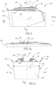
Fig. 1 is a perspective view of a cutting insert in accordance with a first embodiment of the present application; -
Fig. 2 is a detail ofFig. 1 , showing a cutting portion; -
Fig. 3 is a side view of the cutting portion inFig. 2 ; -
Fig. 3a is a detail ofFig. 3 ; -
Fig. 4 is a front view of the cutting portion inFig. 2 ; -
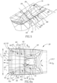
Fig. 5 is a fragmentary perspective view of the cutting portion inFig. 1 , showing an undulating chip forming groove and imaginary extrapolated land surface; -
Fig. 6a is a top view of the cutting portion inFig. 2 ; -
Fig. 6b is an analogous view to that shown inFig. 6a , for the purpose of indicating cross-sectional lines; -
Fig. 7 is a schematic diagram showing the superimposed fragmentary cross sections taken along lines VII-VII and VII'-VII' inFig. 6b ; -
Fig. 8 is a fragmentary cross section view taken along line VIII-VIII inFig. 6b ; -
Fig. 9 is a fragmentary cross section view taken along line IX-IX inFig. 6b ; -
Fig. 10 is a fragmentary cross section view taken along line X-X inFig. 6b ; -
Fig. 11 is a fragmentary cross section view taken along line XI-XI inFig. 6b ; -
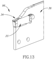
Fig. 12 is a top view of the cutting portion in accordance with a second embodiment of the present application; and -
Fig. 13 is a perspective view of a cutting tool in accordance with the present application. - Where considered appropriate, reference numerals may be repeated among the figures to indicate corresponding or analogous elements.
- In the following description, various aspects of the subject matter of the present application will be described. For purposes of explanation, specific configurations and details are set forth in sufficient detail to provide a thorough understanding of the subject matter of the present application. However, it will also be apparent to one skilled in the art that the subject matter of the present application can be practiced without the specific configurations and details presented herein.
- Attention is first drawn to
Fig. 1 , showing a cuttinginsert 20, in accordance with a first embodiment of the present application. The cuttinginsert 20 can be typically made from cemented carbide and can be coated with a wear-resistant material. In this non-limiting example shown in the drawings, the cuttinginsert 20 includes opposing insert front andrear surfaces peripheral surface 26 that extends between the insert front andrear surfaces peripheral surface 26 extends about an insert central axis I. The insert central axis I can be a longitudinal axis so that the cuttinginsert 20 is elongated. The insert central axis I intersects the insert front andrear surfaces peripheral surface 26 includes opposing insert top andbottom surfaces rear surfaces peripheral surface 26 further includes two opposing insert side surfaces, a firstinsert side surface 32A and a secondinsert side surface 32B that connect the insert front andrear surfaces bottom surfaces insert 20 is configured to be resiliently clamped in an insert pocket 34 (Fig. 13 ) of aninsert holder 36 and is thus formed without a clamping hole for receiving a clamping member (such as a retaining screw) therethrough. - Referring to
Fig. 2 , the cuttinginsert 20 includes a cuttingportion 38, for providing metal removing ability to the cuttinginsert 20. In this non-limiting example shown in the drawings, the cuttinginsert 20 has just one cuttingportion 38, located at one end of the cuttinginsert 20. However, it is understood that there could be two cutting portions 38 (e.g. at each end when the cuttinginsert 20 is double-ended), ormore cutting portions 38, as disclosed in, for example,US 8,939,684 B2 . - Referring to
Figs. 2 ,3 ,4 and6a , the cuttingportion 38 has three mutually perpendicular axes, a cutting portion major axis A, a cutting portion vertical axis V and a cutting portion lateral axis F. The cutting portion major axis A defines a forward to rearward direction DF , DR . In accordance with some embodiments of the subject matter of the present application, in a top view of the cuttingportion 38 viewed along the cutting portion vertical axis V, the cutting portion major axis A can be parallel to, and aligned with, the insert central axis I. However, as seen in a side view of the cuttingportion 38 viewed along the cutting portion lateral axis F (i.e.Fig. 3 ), the cutting portion major axis A and the insert central axis I can extend transversely to one another. The cutting portion vertical axis V defines an upward to downward direction DU , DD . The cutting portion lateral axis F defines at least a feed direction D. In accordance with some embodiments of the subject matter of the present application, the cutting portion lateral axis F can also define a second feed direction D2 , opposite the feed direction D. The cuttingportion 38 has a symmetry plane S that contains the cutting portion major axis A and the cutting portion vertical axis V. - It should be appreciated that use of the terms "forward" and "rearward" throughout the description and claims refer to a relative position in a direction of the cutting portion major axis A, towards the left (DF ) and right (DR ), respectively, in
Figs. 3 and6a . Likewise, it should be appreciated that use of the terms "upward" and "downward" throughout the description and claims refer to a relative position in a direction parallel to the cutting portion vertical axis V, upwards and downwards, respectively, inFigs 3 and 4 . Finally, it should be appreciated that use of the terms "feed direction" and "second feed direction" throughout the description and claims refer to a relative position in a direction parallel to the cutting portion lateral axis F, towards the right and left, respectively, inFig. 4 . - The cutting
portion 38 includes a forward cuttingportion surface 40 formed on theinsert front surface 22. The forwardcutting portion surface 40 is intersected by the cutting portion major axis A and faces in the forward direction DF . - The cutting
portion 38 includes arake surface 42 formed on the inserttop surface 28. Therake surface 42 is intersected by the cutting portion vertical axis V and faces in the upward direction DU . - The cutting
portion 38 also includes arelief surface 44 formed on the firstinsert side surface 32A. Therelief surface 44 is intersected by the cutting portion lateral axis F and faces in the feed direction D. In accordance with some embodiments of the subject matter of the present application, the cuttingportion 38 can include asecond relief surface 48 formed on thesecond side surface 32B. Thesecond relief surface 48 can be intersected by the cutting portion lateral axis F and faces in the second feed direction D2 . The cutting portion vertical axis V extends between therelief surface 44 and thesecond relief surface 48. Thus, the symmetry plane S is positioned between therelief surface 44 and thesecond relief surface 48. - A cutting
portion corner 46 is formed at the intersection of therake surface 42, the forward cuttingportion surface 40, therelief surface 44. In accordance with some embodiments of the subject matter of the present application, a secondcutting portion corner 50 can be formed at the intersection of therake surface 42, the forward cuttingportion surface 40 and thesecond relief surface 48. - The cutting
portion 38 includes acutting edge 52 formed at the intersection of therake surface 42 and therelief surface 44. Referring toFig. 6a , in accordance with some embodiments of the subject matter of the present application, in a top view of the cuttingportion 38, thecutting edge 52 can be straight. Referring toFig. 3a , in a side view of the cuttingportion 38, thecutting edge 52 can be non-straight. Preferably, in such a view, thecutting edge 52 can have a wavy profile, formed by a plurality of cutting edge crests 54 and at least onecutting edge trough 56 that alternate with each other along thecutting edge 52. - Reverting to
Fig. 6a , in accordance with some embodiments of the subject matter of the present application, the cuttingportion 38 can also include asecond cutting edge 58 formed at the intersection of therake surface 42 and thesecond relief surface 48. In a top view of the cuttingportion 38, thesecond cutting edge 58 can be straight but not parallel with thecutting edge 52. - In accordance with some embodiments of the subject matter of the present application, the cutting
portion 38 can include aforward cutting edge 60 formed at an intersection of therake surface 42 and the forward cuttingportion surface 40. The forwardcutting portion surface 40 can thus serve as a relief surface. As shown inFigs. 4 and6a , theforward cutting edge 60 has a forward cutting edge length L, measured in the direction of the cutting portion lateral axis F. In the top view of the cuttingportion 38, the forward cutting edge length L defines the width of the groove cut in the work piece, and also establishes the maximum width of the cuttingportion 38. In accordance with some embodiments of the subject matter of the present application, theforward cutting edge 60 can include two curved forwardcorner cutting edges 62 and a forwardintermediate cutting edge 64 that extends between the two forwardcorner cutting edges 62. The forwardcorner cutting edges 62 can be formed at the cuttingportion corner 46 and the secondcutting portion corner 50, respectively. The forwardintermediate cutting edge 64 can be longer than each of the two forwardcorner cutting edges 62. In the top view of the cuttingportion 38, the forwardintermediate cutting edge 64 can be straight. Theforward cutting edge 60 can be mirror symmetrical about an imaginary longitudinal plane which contains the cutting portion major axis A and passes through the insert top andbottom surfaces forward cutting edge 60, in a top view of the cutting portion 38 (i.e. in a view in front of therake surface 42 viewed along the cutting portion vertical axis V). Thecutting edge 52 andsecond cutting edge 58 can merge with theforward cutting edge 60 at opposite ends thereof. - The
rake surface 42 includes aland 66. Theland 66 acts to strengthen thecutting edge 52. Theland 66 is adjacent thecutting edge 52. Theland 66 extends along thecutting edge 52. Referring toFig. 5 , any point on theland 66 has a land inclination angle θ defined by a tangent line T and a rake plane P, where the tangent line T is perpendicular to thecutting edge 52 in a top view of the cuttingportion 38 and tangentially touches theland 66, and the rake plane P is oriented perpendicular to the cutting portion vertical axis V. Theland 66 extends negatively away from thecutting edge 52. That is to say, theland 66 slopes upwardly from thecutting edge 52 so that the land inclination angle θ is greater than 0°. - In accordance with some embodiments of the subject matter of the present application, the
rake surface 42 can include aforward land 69. Theforward land 69 can be adjacent theforward cutting edge 60. Theforward land 69 can extend along, and negatively away from, theforward cutting edge 60. Referring toFig. 6a , theforward land 69 has a forward land width W that can vary. Preferably, the forward land width W at the forwardintermediate cutting edge 64 can be greater than the forward land width W at the forward cutting corner cutting edges 62. - In accordance with some embodiments of the subject matter of the present application, the
rake surface 42 can include asecond land 70. Thesecond land 70 can be adjacent thesecond cutting edge 58. Thesecond land 70 can extend along, and negatively away from, thesecond cutting edge 58. - The cutting
portion 38 includes a chip-control arrangement 72 at therake surface 42. It is understood that the cuttinginsert 20 in accordance with the subject matter of the present application could comprise one ormore cutting portions 38 with such a chip-control arrangement 72 and one or more other cuttingportions 38 which are devoid of any chip-control arrangement or which are formed with a different chip-control arrangement. The chip-control arrangement 72 is intended to control the flow and/or the shape and size of the swarf and debris resulting from metalworking operations. - Referring to
Figs. 1-6a , the chip-control arrangement 72 includes anelongated projection 74. Theprojection 74 serves to curve the chip in the feed direction D. Theprojection 74 projects from therake surface 42. Theprojection 74 is spaced apart from theland 66. As shown inFig. 5 , in accordance with some embodiments of the subject matter of the present application, theprojection 74 can be spaced apart from theland 66 by achip forming groove 78 that undulates in the rearward direction DR away from the forward cutting portion surface 40 (see alsoFig. 7 ). - The
projection 74 extends in a direction from a rearward portion of the cuttingportion 38 towards a forward portion of the cuttingportion 38. In accordance with some embodiments of the subject matter of the present application, theprojection 74 can include aforwardmost portion 76a and arearmost portion 76b that merge with each other. Therearmost portion 76b of theprojection 74 can form a majority of the length of the projection 74 (e.g. more than half the length of the projection 74). - The
forwardmost portion 76a of theprojection 74 can extend in a direction towards the cuttingportion corner 46. Therearmost portion 76b of theprojection 74 can extend in a direction different than that of theforwardmost portion 76a of theprojection 74. Therearmost portion 76b of theprojection 74 can extend in a direction towards the forward cuttingportion surface 40. Theprojection 74 can increase in distance from thecutting edge 52 with increasing distance from the forward cuttingportion surface 40. Therearmost portion 76b of theprojection 74 can extend longitudinally along a projection longitudinal axis C. In a top view of the cuttingportion 38, the projection longitudinal axis C can form a projection angle α with the cutting portion major axis A. The projection angle α can be in the range, 5° ≤ α ≤ 15°. The projection longitudinal axis C can intersect theforward cutting edge 60. Preferably, the projection longitudinal axis C can intersect the forwardintermediate cutting edge 64. - As seen in
Figs. 10 and11 , in accordance with some embodiments of the subject matter of the present application, theprojection 74 can include two projection flank surfaces 74a and a centralprojection ridge surface 74b that extends therebetween in a widthwise direction of theprojection 74. Theprojection ridge surface 74b can be higher than the twoprojection flank surfaces 74a in a widthwise cross-section. The centralprojection ridge surface 74b at therearmost portion 76b of theprojection 74 can extend along the projection longitudinal axis C (as seen in a top view of the cuttingportion 38, i.e.Fig. 6a ). In the same view, theprojection ridge surface 74b can transition from being closer to thecutting edge 52 than to the cutting portion major axis A, to being closer to the cutting portion major axis A than to thecutting edge 52, as theprojection ridge surface 74b extends in the rearward direction DR . - Referring to
Fig. 8 , showing a cross-sectional view taken in a plane containing the projection longitudinal axis C, in accordance with some embodiments of the subject matter of the present application, theprojection ridge 74b can include a plurality ofprojection crest portions 80 and at least oneprojection trough portions 82, each pair of adjacentprojection crest portions 80 being spaced apart by a respectiveprojection trough portion 82. Eachprojection crest portion 80 is higher than its adjacentprojection trough portions 82. - In accordance with some embodiments of the subject matter of the present application, the plurality of
projection crest portions 80 can be located above thecutting edge 52 as measured in an upward direction DU . The plurality ofprojection crest portions 80 can follow a pattern of increasing height in a rearward direction DR away from the forward cuttingportion surface 40. The at least oneprojection trough portion 82 can be located above thecutting edge 52 as measured in an upward direction Du. - Referring to
Figs. 1-6a , the chip-control arrangement 72 includes a plurality ofelongated protuberances 84. The plurality ofprotuberances 84 serve to curve the chip in the direction of the cutting portion major axis A. The plurality ofprotuberances 84 project from therake surface 42. The plurality ofprotuberances 84 are spaced apart from each other and the forward cuttingportion surface 40. In accordance with some embodiments of the subject matter of the present application, eachprotuberance 84 can extend from a respective one of theprojection crest portions 80. The plurality ofprotuberances 84 may not be identical. Reference is made toFig. 9 , showing a cross-sectional view in a transverse feed plane FP perpendicular to the cutting portion lateral axis F and intersecting the plurality of protuberances 84 (it is noted that the first raised region following thecutting edge 60 is part of the of theprojection 74, specifically theforwardmost portion 76a thereof, and not one of the protuberances 84). It is seen that the plurality ofprotuberances 84 can follow a pattern of increasing height in a rearward direction DR away from the forward cuttingportion surface 40. - As seen in
Fig. 9 , showing a cross-sectional view taken in a protuberance radial plane P2 perpendicular to one of the protuberance longitudinal axes PA and that intersects theprotuberance 84, in accordance with some embodiments of the subject matter of the present application, eachprotuberance 84 can include two protuberance flank surfaces 84a and a centralprotuberance ridge surface 84b that extends therebetween in a widthwise direction of theprotuberance 84. Theprotuberance ridge surface 84b can be higher than the two protuberance flank surfaces 84a in a widthwise cross-section. -
Fig. 10 shows a cross sectional view taken in a protuberance axial plane P1 that contains one of the protuberance longitudinal axes PA and intersects the rake andrelief surfaces protuberance 84 can include a protuberance lowest point LP. The protuberance lowest point LP can be spaced apart from theland 66. The protuberance lowest point LP can be vertically level with thecutting edge 52. - In accordance with some embodiments of the subject matter of the present application, each
protuberance 84 can extend along a protuberance longitudinal axis PA. In a top view of the cuttingportion 38, the protuberance longitudinal axes PA can be parallel with each other. The protuberance longitudinal axes PA may not be co-incident with a respective tangent line T. Each protuberance longitudinal axis PA can form a protuberance angle β with the cutting portion lateral axis F. The protuberance angle β can be in the range, 0° ≤ β ≤ 30°. In this non-limiting example shown in the drawings, the protuberance angle β is equal to 0° (i.e. the protuberance longitudinal axis PA and the cutting portion lateral axis F are parallel to each other). - In accordance with some embodiments of the subject matter of the present application, in the protuberance axial plane P1, a central portion of the
protuberance 84 can have a concave profile. The protuberance lowest point LP can be located at the concave profile. In the protuberance radial plane P2, a central portion of theprotuberance 84 can have a convex profile. - Each
protuberance 84 extends from theprojection 74. By virtue of such a configuration theprojection flank surface 74a closest the cuttingedge 52 can undulate in the rearward direction DR away from the forward cuttingportion surface 40. - Referring to
Fig. 5 , eachprotuberance 84 extends to thecutting edge 52. That is to say, eachprotuberance 84 terminates at thecutting edge 52. Thus, eachprotuberance 84 extends over (or via) theland 66. By virtue of such a configuration, theland 66 includes a plurality of spaced apart upwardly bulgingland portions 86. Each pair of adjacent bulgingland portions 86 are spaced apart by anon-bulging land portion 88. Theland 66 has a land height H, measured in the upward direction DU from the rake plane P that varies along thecutting edge 52. Specifically, the land height H at each bulgingland portion 86 defines a first land height H1 that is greater than a second land height H2 that is defined by the land height H at its adjacentnon-bulging land portions 88. Eachcutting edge crest 54 can be formed at a respective one of the bulgingland portions 86. - Referring to
Fig. 7 , showing a schematic diagram having the superimposed fragmentary cross sections taken along lines VII-VII and VII'-VII' inFig. 6b and also showing the two different tangent lines T, T' related to the respective cross sections, the land 66 (at both the bulging andnon-bulging land portions 86, 88) can include a convexlycurved land portion 68 that extends in the direction of thecutting edge 52. The convexlycurved land portion 68 is also convexly curved in a direction away from thecutting edge 52. Thus, the land inclination angle θ at the convexlycurved land portion 68 can decrease in a direction away from thecutting edge 52. The convexlycurved land portion 68 can be spaced apart from thecutting edge 52. The convexlycurved land portion 68 can be defined by a convexly curved land radius R. The convexly curved land radius R can vary along thecutting edge 52. - The land inclination angle θ at the
cutting edge 52 at each of the bulgingland portions 86 forms a bulging land inclination angle θ1. The land inclination angle θ at thecutting edge 52 at each of thenon-bulging land portions 88 forms a non-bulging land inclination angle θ2. In accordance with some embodiments of the subject matter of the present application, the bulging land inclination angle θ1 at any given bulgingland portion 86 can be greater than the non-bulging land inclination angles θ2 at its adjacentnon-bulging land portions 88. Thus, as seen inFig. 5 , showing an imaginary extrapolatedland surface 89 defined by the extrapolation of theland 66 at thecutting edge 52, the land inclination angle θ at thecutting edge 52 can vary in alternating increasing and decreasing fashion, along thecutting edge 52. The bulging land inclination angle θ1 at any given bulgingland portion 86 can be greater than the non-bulging land inclination angles θ2 at its adjacentnon-bulging land portions 88 by no more than 5°. The bulging land inclination angle θ1 can be in the range, 20° ≤ θ1 ≤ 40°. The non-bulging land inclination angle θ2 can be in the range, 5°≤ θ2 ≤ 30°. - Generally speaking, the
land 66 transitions into thechip forming groove 78 where the surface upon which it extends changes from a negative orientation to a positive orientation. However, it is noted that at the bulgingland portions 86 theland 66 may not transition to a positive orientation. - In accordance with some embodiments of the subject matter of the present application, the chip-
control arrangement 72 can include an elongatedsecond projection 90. Thesecond projection 90 can project from therake surface 42. Thesecond projection 90 can extend in a direction towards a forward portion of the cuttingportion 38. Thesecond projection 90 can be spaced apart from thesecond land 70. - In accordance with some embodiments of the subject matter of the present application, the chip-
control arrangement 72 can include a plurality of elongatedsecond protuberances 92. The plurality ofsecond protuberances 92 can project from therake surface 42. The plurality ofsecond protuberances 92 can be spaced apart from each other and the forward cuttingportion surface 40. Eachsecond protuberance 92 can extend from thesecond projection 90 to thesecond cutting edge 58. Eachsecond protuberance 92 can extend to thesecond cutting edge 58. Eachsecond protuberance 92 can extend over (i.e. via) thesecond land 70. Thus, as seen inFig. 2 , thesecond land 70 can include a plurality of spaced apart second bulgingland portions 94. The chip-control arrangement 72 can exhibit mirror symmetry about the symmetry plane S Similarly, the cuttingportion 38 can exhibit mirror symmetry about the symmetry plane S. - It should be appreciated that any or all of the features relating to the
relief surface 44, cuttingportion corner 46, cuttingedge 52,land 66,projection 74,protuberance 84 and bulgingland portion 86 can apply to thesecond relief surface 48, second cuttingportion corner 50,second cutting edge 58,second land 70,second projection 90,second protuberance 92 and second bulgingland portion 94, respectively. - Referring to
Fig. 13 , a second aspect of the present application relates to anon-rotary cutting tool 96. For example, the cuttingtool 96 can be designed for turning cutting operations as opposed to milling or drilling cutting operation. The cuttingtool 96 includes a cuttinginsert 20 and aninsert holder 36. Theinsert holder 36 includes aninsert pocket 34, with the cuttinginsert 20 releasable retained in theinsert pocket 34. - Reference is now made to
Fig. 13 showing a second embodiment. This embodiment has been found to work particularly well for grooving cutting inserts having a width (i.e. forward cutting edge length L) equal to 6 mm. - It should be noted that one feature of the subject matter of the present application is that the chip-
control arrangement 72 has been found to be effective for turning and in particular groove-turning cutting methods. - It should be further noted that one feature of the subject matter of the present application is that the chip-
control arrangement 72 has been found to be effective for cutting different metal work-piece materials such as steel, stainless steel and high temperature metal alloys, such as nickel. - It should be yet further noted that one feature of the subject matter of the present application is that the chip-
control arrangement 72 has been found to be effective for multiple applications, such as full width grooving, partial (finish) grooving, finish turning, and turning. - Although the subject matter of the present application has been described to a certain degree of particularity, it should be understood that various alterations and modifications could be made without departing from the scope of the invention as hereinafter claimed.
Claims (15)
- A cutting insert (20) comprising:
a cutting portion (38), having a cutting portion major axis (A) defining opposite forward to rearward directions (DF, DR) and a cutting portion lateral axis (F), oriented perpendicular to the cutting portion major axis (A) in a top view of the cutting portion (38), defining a feed direction (D), the cutting portion (38) comprising :a cutting portion corner (46) formed at the intersection of an upward facing rake surface (42), a forward facing forward cutting portion surface (40) and a relief surface (44) facing in the feed direction (D);a cutting edge (52) formed at an intersection of the rake surface (42) and the relief surface (44);a land (66) located on the rake surface (42); anda chip-control arrangement (72) at the rake surface (42) comprising:an elongated projection (74) projecting from the rake surface (42), spaced apart from the land (66), and extending in a direction from a rearward portion towards a forward portion of the cutting portion (38);characterised in that:the land (66) extends along, and negatively away from, the said cutting edge (52); andthe chip-control arrangement (72) at the rake surface (42) comprises
a plurality of elongated protuberances (84) projecting from the rake surface (42) and being spaced apart from each other and the forward cutting portion surface (40), each protuberance (84) extending from the projection (74) to the cutting edge (52), so that the land (66) comprises a plurality of spaced apart upwardly bulging land portions (86). - The cutting insert (20) according to claim 1, wherein:each pair of adjacent bulging land portions (86) are spaced apart by a non-bulging land portion (88);the land inclination angle (θ) at the cutting edge (52) at each of the bulging land portions (86) forms a bulging land inclination angle (θ1);the land inclination angle (θ) at the cutting edge (52) at each of the non-bulging land portions (88) forms a non-bulging land inclination angle (θ2);the bulging land inclination angle (θ1) at any given bulging land portion (86) is greater than the non-bulging land inclination angles (θ2) at its adjacent non-bulging land portions (88), preferably by no more than 5°, and further preferably,the bulging land inclination angle (θ1) is in the range, 20° ≤ the bulging land inclination angle (θ1) ≤ 40°; andthe non-bulging land inclination angle (θ2) is in the range, 5° ≤ the non-bulging land inclination angle (θ2) ≤ 30°.he non-bulging land inclination angle (θ2) is in the range, 5° ≤ (θ2) ≤ 30°.
- The cutting insert (20) according to claim 2, wherein the bulging land inclination angles (θ1) follow a pattern of increasing value in direction away from the forward cutting portion surface (40).
- The cutting insert (20) according to any one of claims 1-3, wherein in a cross-sectional view taken in a transverse feed plane (FP) perpendicular to the cutting portion lateral axis (F) and intersecting the plurality of protuberances (84), the plurality of protuberances (84) follow a pattern of increasing height in a rearward direction (DR) away from the forward cutting portion surface (40).
- The cutting insert (20) according to any one of claims 1-4, wherein the projection (74) is spaced apart from the land (66) by a chip forming groove (78) that undulates in the rearward direction (DR) away from the forward cutting portion surface (40).
- The cutting insert (20) according to any one of claims 1-5, wherein the projection (74) increases in distance from the cutting edge (52) with increasing distance from the forward cutting portion surface (40).
- The cutting insert (20) according to any one of claims 1-6, wherein a forwardmost portion (76a) of the projection (74) extends in a direction towards the cutting portion corner (46).
- The cutting insert (20) according to any one of claims 1-7, wherein:a rearmost portion (76b) of the projection (74) extends longitudinally along a projection longitudinal axis (C);in a top view of the cutting portion (38), the projection longitudinal axis (C) forms a projection angle (α) with the cutting portion major axis (A); andthe projection angle (α) is in the range, 5° ≤ (α) ≤ 15°.
- The cutting insert (20) according to any one of claims 1-8, wherein:the projection (74) comprises two projection flank surfaces (74a) and a central disposed projection ridge surface (74b) that extends therebetween in a widthwise direction of the projection (74), the projection ridge surface (74b) being higher than the two projection flank surfaces (74a) in a widthwise cross-section, and preferably in a top view of the cutting portion (38), the projection ridge surface (74b) is located between the cutting portion major axis (A) and the cutting edge (52), and further preferably,the projection ridge surface (74b) transitions from being closer to the cutting edge (52) than to the cutting portion major axis (A), to being closer to the cutting portion major axis (A) than to the cutting edge (52), as the projection ridge surface (74b) extends in the rearward direction (DR).
- The cutting insert (20) according to any one of claims 1-9, wherein:the projection ridge surface (74b) comprises a plurality of projection crest portions (80) and a plurality of projection trough portions (82), each adjacent pair of projection crest portions (80) being spaced apart by a respective projection trough portion (82), and each projection crest portion (80) being higher than its adjacent projection trough portions (82); andeach protuberance (84) extends from a respective one of the projection crest portions (80), and preferably,the plurality of projection crest portions (80) follow a pattern of increasing height in a rearward direction (DR) away from the forward cutting portion surface (40), and further preferably,the plurality of projection crest portions (80) are located above the cutting edge (52) as measured in the upward direction (DU).
- The cutting insert (20) according to any one of claims 1-10, wherein:each protuberance (84) extends along a protuberance longitudinal axis (PA);in a top view of the cutting portion (38), each protuberance longitudinal axis (PA) forms a protuberance angle (β) with the cutting portion lateral axis (F); andthe protuberance angle (β) is in the range, 0° ≤ the protuberance angle (β) ≤ 30°, and preferably,in a top view of the cutting portion (38), the protuberance longitudinal axes (PA) are parallel with each other, and further preferably,in a cross-sectional view taken in a protuberance axial plane (P1) containing one of the protuberance longitudinal axes (PA) and intersecting the rake and relief surfaces (42, 44), a central portion of the protuberance (84) has a concave profile, and yet further preferably,in a cross-sectional view taken in a protuberance radial plane (P2) perpendicular to one of the protuberance longitudinal axis (PA) and intersecting the protuberance (84), a central portion of the protuberance (84) has a convex profile.
- The cutting insert (20) according to any one of claims 1-11, wherein in a side view of the cutting portion (38), the cutting edge (52) has a wavy profile, formed by a plurality of cutting edge crests (54) and at least one cutting edge trough (56), each cutting edge crest (54) being formed at a respective one of the bulging land portions (86).
- The cutting insert (20) according to any one of claims 1-12, wherein the land (66) comprises a convexly curved land portion (68) extending in the direction of the cutting edge (52) and that is convexly curved in direction away from the cutting edge (52).
- The cutting insert (20) according to any one of claims 1-13, wherein:
the cutting portion lateral axis (F) defines a second feed direction (D2), opposite the feed direction (D), the cutting portion (38) further comprising:a second cutting portion corner (50) formed at the intersection of the rake surface (42), the forward cutting portion surface (40) and a second relief surface (48) that faces in the second feed direction (D2);a second cutting edge (58) formed at an intersection of the rake surface (42) and the second relief surface (48);a second land (70) located on the rake surface (42) and extending along, and negatively away from, the second cutting edge (58); wherein
the chip-control arrangement (72) further comprises:an elongated second projection (90) projecting from the rake surface (42), spaced apart from the second land (70), and extending in a direction towards a forward portion of the cutting portion (38); anda plurality of elongated second protuberances (92) projecting from the rake surface (42) and being spaced apart from each other and the forward cutting portion surface (40), each second protuberance (92) extending from the second projection (90) to the second cutting edge (58), so that the second land (70) comprises a plurality of spaced apart second bulging land portions (94), and preferablythe cutting portion (38) further comprises a forward cutting edge (60) formed at an intersection of the rake surface (42) and the forward cutting portion surface (40); andin a top view of the cutting portion (38), the forward cutting edge (60) has a forward cutting edge length (L) which also defines a maximum width dimension of the cutting insert (20) in a direction perpendicular to the cutting portion major axis (A), and further preferably,the chip-control arrangement (72) exhibits mirror symmetry about a symmetry plane (S) that contains the cutting portion major axis (A) and a cutting portion vertical axis (V) which is perpendicular to the cutting portion major axis (A) and which extends between the relief surface (44) and the second relief surface (48). - A non-rotary cutting tool (96), comprising:a cutting insert (20) in accordance with any one of claims 1-14; andan insert holder (36) comprising an insert pocket (34); wherein:
the cutting insert (20) is releasably retained in the insert pocket (34).
Applications Claiming Priority (2)
| Application Number | Priority Date | Filing Date | Title |
|---|---|---|---|
| US201862636225P | 2018-02-28 | 2018-02-28 | |
| PCT/IL2019/050036 WO2019167037A1 (en) | 2018-02-28 | 2019-01-08 | Cutting insert having land with spaced apart upwardly bulging land portions and non-rotary cutting tool provided therewith |
Publications (2)
| Publication Number | Publication Date |
|---|---|
| EP3758874A1 EP3758874A1 (en) | 2021-01-06 |
| EP3758874B1 true EP3758874B1 (en) | 2024-10-23 |
Family
ID=65228609
Family Applications (1)
| Application Number | Title | Priority Date | Filing Date |
|---|---|---|---|
| EP19701739.5A Active EP3758874B1 (en) | 2018-02-28 | 2019-01-08 | Cutting insert having land with spaced apart upwardly bulging land portions and non-rotary cutting tool provided therewith |
Country Status (13)
| Country | Link |
|---|---|
| US (1) | US10987740B2 (en) |
| EP (1) | EP3758874B1 (en) |
| JP (1) | JP7275149B2 (en) |
| KR (1) | KR102587432B1 (en) |
| CN (1) | CN111770805B (en) |
| CA (1) | CA3098545A1 (en) |
| ES (1) | ES2993353T3 (en) |
| IL (1) | IL276550B2 (en) |
| PL (1) | PL3758874T3 (en) |
| PT (1) | PT3758874T (en) |
| RU (1) | RU2768817C1 (en) |
| TW (1) | TWI773866B (en) |
| WO (1) | WO2019167037A1 (en) |
Families Citing this family (5)
| Publication number | Priority date | Publication date | Assignee | Title |
|---|---|---|---|---|
| TWI773866B (en) | 2018-02-28 | 2022-08-11 | 以色列商艾斯卡公司 | Cutting insert having land with spaced apart upwardly bulging land portions and non-rotary cutting tool provided therewith |
| JP6923854B1 (en) * | 2021-02-26 | 2021-08-25 | 株式会社タンガロイ | Cutting insert |
| USD953396S1 (en) * | 2021-04-29 | 2022-05-31 | Korloy Inc. | Grooving insert for machine tools for metalworking |
| US11717895B2 (en) * | 2021-05-21 | 2023-08-08 | Taegutec Ltd. | Cutting insert and cutting tool assembly including same |
| JP7741484B2 (en) * | 2024-02-27 | 2025-09-18 | 株式会社タンガロイ | cutting tools |
Citations (10)
| Publication number | Priority date | Publication date | Assignee | Title |
|---|---|---|---|---|
| US4969779A (en) | 1989-02-10 | 1990-11-13 | Iscar Ltd. | Cutting insert |
| DE4141368A1 (en) | 1991-12-14 | 1993-06-17 | Krupp Widia Gmbh | CUTTING INSERT |
| WO1996011763A1 (en) | 1994-10-17 | 1996-04-25 | Widia Gmbh | Polygonal cutting insert |
| US5725334A (en) | 1993-03-29 | 1998-03-10 | Widia Gmbh | Cutting insert |
| JP2005288613A (en) | 2004-03-31 | 2005-10-20 | Mitsubishi Materials Corp | Throwaway tip |
| EP1702702A1 (en) | 2005-03-16 | 2006-09-20 | Sandvik Intellectual Property AB | Face milling insert |
| EP2412464A1 (en) | 2009-03-24 | 2012-02-01 | Hitachi Tool Engineering, Ltd. | Cutting tip replacement type rotary tool |
| CN103009333A (en) | 2012-12-24 | 2013-04-03 | 株洲欧科亿硬质合金有限公司 | Indexable cutting insert for rough machining |
| WO2014017623A1 (en) | 2012-07-26 | 2014-01-30 | 京セラ株式会社 | Cutting insert and cutting tool, and method for manufacturing cut object using the same |
| CN205650832U (en) | 2016-04-11 | 2016-10-19 | 大连远东钨业科技股份有限公司 | But rough machining transposition numerical control turning blade |
Family Cites Families (33)
| Publication number | Priority date | Publication date | Assignee | Title |
|---|---|---|---|---|
| US3654681A (en) * | 1970-04-22 | 1972-04-11 | Warner Swasey Co | Cutoff tool having improved chip relieving surface |
| US4629372A (en) * | 1981-02-02 | 1986-12-16 | Manchester Tool Company | Chip-controlling insert |
| CA1194283A (en) * | 1981-02-02 | 1985-10-01 | Mark F. Huston | Regrindable chip controlling insert |
| SE454248B (en) * | 1986-08-18 | 1988-04-18 | Sandvik Ab | HAPPENS FOR SAVING AND CUTTING |
| SU1465176A2 (en) * | 1986-12-01 | 1989-03-15 | Предприятие П/Я Р-6564 | Cutting bit |
| SU1720802A1 (en) * | 1990-03-11 | 1992-03-23 | Научно-Исследовательская Лаборатория "Карбидные Материалы" | Cutting tool |
| SU1710201A1 (en) * | 1990-05-04 | 1992-02-07 | Новосибирский Филиал Специального Производственно-Технологического Бюро "Оргпримтвердосплав" | Cutting bit |
| GB2290994B (en) * | 1994-07-05 | 1998-06-10 | Valenite Inc | Cutting insert |
| JPH10505012A (en) | 1994-09-12 | 1998-05-19 | ヴィディア ゲゼルシャフト ミット ベシュレンクテル ハフツング | Cutting inserts for cutting workpieces |
| DE19528851A1 (en) * | 1995-08-05 | 1997-02-06 | Widia Gmbh | Polygonal cutting insert |
| SE505165C2 (en) * | 1996-06-06 | 1997-07-07 | Sandvik Ab | Cut for groove knitting |
| SE514872C2 (en) * | 1998-09-09 | 2001-05-07 | Sandvik Ab | Cutter for track turning |
| JP4465809B2 (en) * | 1999-07-09 | 2010-05-26 | 三菱マテリアル株式会社 | Throwaway tip |
| SE525729C2 (en) * | 2002-01-31 | 2005-04-12 | Sandvik Ab | Cutting for grooving and profiling |
| CA2503813C (en) * | 2002-10-18 | 2008-12-23 | Manchester Tool Company | Tool holder and metal cutting insert with chip breaking surfaces |
| IL159188A (en) * | 2003-12-04 | 2008-08-07 | Uzi Gati | Cutting insert for grooving operations |
| US6979153B1 (en) * | 2004-08-20 | 2005-12-27 | Sandvik Ab | Deep-grooving insert having stepped cutting edge |
| EP1980348B1 (en) | 2007-03-30 | 2012-03-07 | Mitsubishi Materials Corporation | Cutting insert |
| KR100901470B1 (en) * | 2007-07-05 | 2009-06-08 | 대구텍 주식회사 | Cutting insert with corner recess |
| US8770895B2 (en) * | 2010-01-29 | 2014-07-08 | Kyocera Corporation | Cutting insert, cutting tool, and method of cutting workpiece using them |
| WO2012043629A1 (en) | 2010-09-29 | 2012-04-05 | 京セラ株式会社 | Cutting insert, cutting tool, and method for producing cut product using said cutting insert and cutting tool |
| CN103379975B (en) | 2011-02-28 | 2016-02-24 | 京瓷株式会社 | Cutting tool and cutting element, and the manufacture method of machining thing using them |
| US8939684B2 (en) | 2012-05-15 | 2015-01-27 | Iscar, Ltd. | Cutting insert with chip-control arrangement having recess depths and projection heights which increase with distance from cutting edge |
| DE102012111576B4 (en) | 2012-11-29 | 2022-05-25 | Kennametal Inc. | Cutting insert with coolant channel and cutting tool with a tool holder and such a cutting insert |
| JP6206801B2 (en) * | 2013-09-09 | 2017-10-04 | 住友電工ハードメタル株式会社 | Cutting insert |
| US9421615B2 (en) * | 2014-04-10 | 2016-08-23 | Iscar, Ltd. | Cutting tool and cutting insert having exactly four cutting portions therefor |
| US10076788B2 (en) * | 2014-05-20 | 2018-09-18 | Iscar, Ltd. | Cutting insert with chip-control arrangement |
| US9579727B2 (en) | 2014-05-28 | 2017-02-28 | Kennametal Inc. | Cutting assembly with cutting insert having enhanced coolant delivery |
| EP3153260B1 (en) | 2015-10-09 | 2018-05-23 | Sandvik Intellectual Property AB | Turning insert and method |
| EP3153261B1 (en) * | 2015-10-09 | 2018-04-04 | Sandvik Intellectual Property AB | Turning insert and method |
| JP2017177285A (en) | 2016-03-30 | 2017-10-05 | 日本特殊陶業株式会社 | Cutting insert |
| CN107626936A (en) * | 2017-09-23 | 2018-01-26 | 哈尔滨理工大学 | A kind of new anti-attrition turning insert of high temperature alloy |
| TWI773866B (en) | 2018-02-28 | 2022-08-11 | 以色列商艾斯卡公司 | Cutting insert having land with spaced apart upwardly bulging land portions and non-rotary cutting tool provided therewith |
-
2019
- 2019-01-02 TW TW108100021A patent/TWI773866B/en active
- 2019-01-03 US US16/238,958 patent/US10987740B2/en active Active
- 2019-01-08 ES ES19701739T patent/ES2993353T3/en active Active
- 2019-01-08 PT PT197017395T patent/PT3758874T/en unknown
- 2019-01-08 RU RU2020126298A patent/RU2768817C1/en active
- 2019-01-08 CN CN201980015556.9A patent/CN111770805B/en active Active
- 2019-01-08 JP JP2020537702A patent/JP7275149B2/en active Active
- 2019-01-08 IL IL276550A patent/IL276550B2/en unknown
- 2019-01-08 KR KR1020207024892A patent/KR102587432B1/en active Active
- 2019-01-08 CA CA3098545A patent/CA3098545A1/en active Pending
- 2019-01-08 WO PCT/IL2019/050036 patent/WO2019167037A1/en not_active Ceased
- 2019-01-08 PL PL19701739.5T patent/PL3758874T3/en unknown
- 2019-01-08 EP EP19701739.5A patent/EP3758874B1/en active Active
Patent Citations (10)
| Publication number | Priority date | Publication date | Assignee | Title |
|---|---|---|---|---|
| US4969779A (en) | 1989-02-10 | 1990-11-13 | Iscar Ltd. | Cutting insert |
| DE4141368A1 (en) | 1991-12-14 | 1993-06-17 | Krupp Widia Gmbh | CUTTING INSERT |
| US5725334A (en) | 1993-03-29 | 1998-03-10 | Widia Gmbh | Cutting insert |
| WO1996011763A1 (en) | 1994-10-17 | 1996-04-25 | Widia Gmbh | Polygonal cutting insert |
| JP2005288613A (en) | 2004-03-31 | 2005-10-20 | Mitsubishi Materials Corp | Throwaway tip |
| EP1702702A1 (en) | 2005-03-16 | 2006-09-20 | Sandvik Intellectual Property AB | Face milling insert |
| EP2412464A1 (en) | 2009-03-24 | 2012-02-01 | Hitachi Tool Engineering, Ltd. | Cutting tip replacement type rotary tool |
| WO2014017623A1 (en) | 2012-07-26 | 2014-01-30 | 京セラ株式会社 | Cutting insert and cutting tool, and method for manufacturing cut object using the same |
| CN103009333A (en) | 2012-12-24 | 2013-04-03 | 株洲欧科亿硬质合金有限公司 | Indexable cutting insert for rough machining |
| CN205650832U (en) | 2016-04-11 | 2016-10-19 | 大连远东钨业科技股份有限公司 | But rough machining transposition numerical control turning blade |
Also Published As
| Publication number | Publication date |
|---|---|
| ES2993353T3 (en) | 2024-12-27 |
| IL276550B2 (en) | 2024-02-01 |
| WO2019167037A1 (en) | 2019-09-06 |
| CA3098545A1 (en) | 2019-09-06 |
| US20190262908A1 (en) | 2019-08-29 |
| CN111770805B (en) | 2023-07-28 |
| EP3758874A1 (en) | 2021-01-06 |
| IL276550A (en) | 2020-09-30 |
| PL3758874T3 (en) | 2025-01-13 |
| TW201936299A (en) | 2019-09-16 |
| CN111770805A (en) | 2020-10-13 |
| JP2021514859A (en) | 2021-06-17 |
| BR112020017454A2 (en) | 2020-12-22 |
| JP7275149B2 (en) | 2023-05-17 |
| PT3758874T (en) | 2024-11-18 |
| KR102587432B1 (en) | 2023-10-11 |
| US10987740B2 (en) | 2021-04-27 |
| RU2768817C1 (en) | 2022-03-24 |
| TWI773866B (en) | 2022-08-11 |
| KR20200124682A (en) | 2020-11-03 |
| IL276550B1 (en) | 2023-10-01 |
Similar Documents
| Publication | Publication Date | Title |
|---|---|---|
| EP3758874B1 (en) | Cutting insert having land with spaced apart upwardly bulging land portions and non-rotary cutting tool provided therewith | |
| CA2541901C (en) | Cutting insert for high feed face milling | |
| EP2214857B1 (en) | Tangential cutting insert | |
| AU766054B2 (en) | Cutting insert | |
| US10384268B1 (en) | Grooving insert having rearwardly pointing arrowhead-shaped chip former | |
| IL106536A (en) | Insert for a milling cutter | |
| JP6361948B2 (en) | Cutting inserts and cutting tools | |
| EP3624970B1 (en) | Cutting insert having a split cutting edge with leading and trailing component cutting edges | |
| CN110000400B (en) | Double-sided groove type cutting blade | |
| EP1425126B1 (en) | Cutting insert | |
| BR112020017454B1 (en) | CUTTING INSERT AND NON-ROTARY CUTTING TOOL | |
| JPH11197909A (en) | Indexable tip |
Legal Events
| Date | Code | Title | Description |
|---|---|---|---|
| STAA | Information on the status of an ep patent application or granted ep patent |
Free format text: STATUS: UNKNOWN |
|
| STAA | Information on the status of an ep patent application or granted ep patent |
Free format text: STATUS: THE INTERNATIONAL PUBLICATION HAS BEEN MADE |
|
| PUAI | Public reference made under article 153(3) epc to a published international application that has entered the european phase |
Free format text: ORIGINAL CODE: 0009012 |
|
| STAA | Information on the status of an ep patent application or granted ep patent |
Free format text: STATUS: REQUEST FOR EXAMINATION WAS MADE |
|
| 17P | Request for examination filed |
Effective date: 20200907 |
|
| AK | Designated contracting states |
Kind code of ref document: A1 Designated state(s): AL AT BE BG CH CY CZ DE DK EE ES FI FR GB GR HR HU IE IS IT LI LT LU LV MC MK MT NL NO PL PT RO RS SE SI SK SM TR |
|
| AX | Request for extension of the european patent |
Extension state: BA ME |
|
| DAV | Request for validation of the european patent (deleted) | ||
| DAX | Request for extension of the european patent (deleted) | ||
| GRAP | Despatch of communication of intention to grant a patent |
Free format text: ORIGINAL CODE: EPIDOSNIGR1 |
|
| STAA | Information on the status of an ep patent application or granted ep patent |
Free format text: STATUS: GRANT OF PATENT IS INTENDED |
|
| INTG | Intention to grant announced |
Effective date: 20240606 |
|
| GRAS | Grant fee paid |
Free format text: ORIGINAL CODE: EPIDOSNIGR3 |
|
| GRAA | (expected) grant |
Free format text: ORIGINAL CODE: 0009210 |
|
| STAA | Information on the status of an ep patent application or granted ep patent |
Free format text: STATUS: THE PATENT HAS BEEN GRANTED |
|
| AK | Designated contracting states |
Kind code of ref document: B1 Designated state(s): AL AT BE BG CH CY CZ DE DK EE ES FI FR GB GR HR HU IE IS IT LI LT LU LV MC MK MT NL NO PL PT RO RS SE SI SK SM TR |
|
| P01 | Opt-out of the competence of the unified patent court (upc) registered |
Free format text: CASE NUMBER: APP_51827/2024 Effective date: 20240916 |
|
| REG | Reference to a national code |
Ref country code: GB Ref legal event code: FG4D |
|
| REG | Reference to a national code |
Ref country code: CH Ref legal event code: EP |
|
| REG | Reference to a national code |
Ref country code: DE Ref legal event code: R096 Ref document number: 602019060743 Country of ref document: DE |
|
| REG | Reference to a national code |
Ref country code: PT Ref legal event code: SC4A Ref document number: 3758874 Country of ref document: PT Date of ref document: 20241118 Kind code of ref document: T Free format text: AVAILABILITY OF NATIONAL TRANSLATION Effective date: 20241112 |
|
| REG | Reference to a national code |
Ref country code: IE Ref legal event code: FG4D |
|
| REG | Reference to a national code |
Ref country code: SE Ref legal event code: TRGR |
|
| REG | Reference to a national code |
Ref country code: ES Ref legal event code: FG2A Ref document number: 2993353 Country of ref document: ES Kind code of ref document: T3 Effective date: 20241227 |
|
| REG | Reference to a national code |
Ref country code: LT Ref legal event code: MG9D |
|
| REG | Reference to a national code |
Ref country code: NL Ref legal event code: MP Effective date: 20241023 |
|
| PG25 | Lapsed in a contracting state [announced via postgrant information from national office to epo] |
Ref country code: NL Free format text: LAPSE BECAUSE OF FAILURE TO SUBMIT A TRANSLATION OF THE DESCRIPTION OR TO PAY THE FEE WITHIN THE PRESCRIBED TIME-LIMIT Effective date: 20241023 |
|
| PG25 | Lapsed in a contracting state [announced via postgrant information from national office to epo] |
Ref country code: NL Free format text: LAPSE BECAUSE OF FAILURE TO SUBMIT A TRANSLATION OF THE DESCRIPTION OR TO PAY THE FEE WITHIN THE PRESCRIBED TIME-LIMIT Effective date: 20241023 |
|
| PG25 | Lapsed in a contracting state [announced via postgrant information from national office to epo] |
Ref country code: IS Free format text: LAPSE BECAUSE OF FAILURE TO SUBMIT A TRANSLATION OF THE DESCRIPTION OR TO PAY THE FEE WITHIN THE PRESCRIBED TIME-LIMIT Effective date: 20250223 Ref country code: HR Free format text: LAPSE BECAUSE OF FAILURE TO SUBMIT A TRANSLATION OF THE DESCRIPTION OR TO PAY THE FEE WITHIN THE PRESCRIBED TIME-LIMIT Effective date: 20241023 |
|
| PGFP | Annual fee paid to national office [announced via postgrant information from national office to epo] |
Ref country code: DE Payment date: 20241205 Year of fee payment: 7 |
|
| PG25 | Lapsed in a contracting state [announced via postgrant information from national office to epo] |
Ref country code: FI Free format text: LAPSE BECAUSE OF FAILURE TO SUBMIT A TRANSLATION OF THE DESCRIPTION OR TO PAY THE FEE WITHIN THE PRESCRIBED TIME-LIMIT Effective date: 20241023 |
|
| PG25 | Lapsed in a contracting state [announced via postgrant information from national office to epo] |
Ref country code: BG Free format text: LAPSE BECAUSE OF FAILURE TO SUBMIT A TRANSLATION OF THE DESCRIPTION OR TO PAY THE FEE WITHIN THE PRESCRIBED TIME-LIMIT Effective date: 20241023 |
|
| PGFP | Annual fee paid to national office [announced via postgrant information from national office to epo] |
Ref country code: ES Payment date: 20250203 Year of fee payment: 7 |
|
| PG25 | Lapsed in a contracting state [announced via postgrant information from national office to epo] |
Ref country code: NO Free format text: LAPSE BECAUSE OF FAILURE TO SUBMIT A TRANSLATION OF THE DESCRIPTION OR TO PAY THE FEE WITHIN THE PRESCRIBED TIME-LIMIT Effective date: 20250123 |
|
| PG25 | Lapsed in a contracting state [announced via postgrant information from national office to epo] |
Ref country code: GR Free format text: LAPSE BECAUSE OF FAILURE TO SUBMIT A TRANSLATION OF THE DESCRIPTION OR TO PAY THE FEE WITHIN THE PRESCRIBED TIME-LIMIT Effective date: 20250124 Ref country code: LV Free format text: LAPSE BECAUSE OF FAILURE TO SUBMIT A TRANSLATION OF THE DESCRIPTION OR TO PAY THE FEE WITHIN THE PRESCRIBED TIME-LIMIT Effective date: 20241023 |
|
| PGFP | Annual fee paid to national office [announced via postgrant information from national office to epo] |
Ref country code: AT Payment date: 20241205 Year of fee payment: 7 Ref country code: CH Payment date: 20250201 Year of fee payment: 7 |
|
| PGFP | Annual fee paid to national office [announced via postgrant information from national office to epo] |
Ref country code: IT Payment date: 20241205 Year of fee payment: 7 |
|
| PG25 | Lapsed in a contracting state [announced via postgrant information from national office to epo] |
Ref country code: RS Free format text: LAPSE BECAUSE OF FAILURE TO SUBMIT A TRANSLATION OF THE DESCRIPTION OR TO PAY THE FEE WITHIN THE PRESCRIBED TIME-LIMIT Effective date: 20250123 |
|
| PGFP | Annual fee paid to national office [announced via postgrant information from national office to epo] |
Ref country code: TR Payment date: 20250106 Year of fee payment: 7 |
|
| PG25 | Lapsed in a contracting state [announced via postgrant information from national office to epo] |
Ref country code: SM Free format text: LAPSE BECAUSE OF FAILURE TO SUBMIT A TRANSLATION OF THE DESCRIPTION OR TO PAY THE FEE WITHIN THE PRESCRIBED TIME-LIMIT Effective date: 20241023 |
|
| PG25 | Lapsed in a contracting state [announced via postgrant information from national office to epo] |
Ref country code: DK Free format text: LAPSE BECAUSE OF FAILURE TO SUBMIT A TRANSLATION OF THE DESCRIPTION OR TO PAY THE FEE WITHIN THE PRESCRIBED TIME-LIMIT Effective date: 20241023 |
|
| PG25 | Lapsed in a contracting state [announced via postgrant information from national office to epo] |
Ref country code: EE Free format text: LAPSE BECAUSE OF FAILURE TO SUBMIT A TRANSLATION OF THE DESCRIPTION OR TO PAY THE FEE WITHIN THE PRESCRIBED TIME-LIMIT Effective date: 20241023 |
|
| REG | Reference to a national code |
Ref country code: DE Ref legal event code: R026 Ref document number: 602019060743 Country of ref document: DE |
|
| PG25 | Lapsed in a contracting state [announced via postgrant information from national office to epo] |
Ref country code: RO Free format text: LAPSE BECAUSE OF FAILURE TO SUBMIT A TRANSLATION OF THE DESCRIPTION OR TO PAY THE FEE WITHIN THE PRESCRIBED TIME-LIMIT Effective date: 20241023 |
|
| PG25 | Lapsed in a contracting state [announced via postgrant information from national office to epo] |
Ref country code: SK Free format text: LAPSE BECAUSE OF FAILURE TO SUBMIT A TRANSLATION OF THE DESCRIPTION OR TO PAY THE FEE WITHIN THE PRESCRIBED TIME-LIMIT Effective date: 20241023 |
|
| PLBI | Opposition filed |
Free format text: ORIGINAL CODE: 0009260 |
|
| PLAX | Notice of opposition and request to file observation + time limit sent |
Free format text: ORIGINAL CODE: EPIDOSNOBS2 |
|
| 26 | Opposition filed |
Opponent name: KENNAMETAL INC. Effective date: 20250718 |
|
| PG25 | Lapsed in a contracting state [announced via postgrant information from national office to epo] |
Ref country code: LU Free format text: LAPSE BECAUSE OF NON-PAYMENT OF DUE FEES Effective date: 20250108 Ref country code: MC Free format text: LAPSE BECAUSE OF FAILURE TO SUBMIT A TRANSLATION OF THE DESCRIPTION OR TO PAY THE FEE WITHIN THE PRESCRIBED TIME-LIMIT Effective date: 20241023 |
|
| PG25 | Lapsed in a contracting state [announced via postgrant information from national office to epo] |
Ref country code: BE Free format text: LAPSE BECAUSE OF NON-PAYMENT OF DUE FEES Effective date: 20250131 |
|
| REG | Reference to a national code |
Ref country code: BE Ref legal event code: MM Effective date: 20250131 |
|
| PLBB | Reply of patent proprietor to notice(s) of opposition received |
Free format text: ORIGINAL CODE: EPIDOSNOBS3 |
|
| PGFP | Annual fee paid to national office [announced via postgrant information from national office to epo] |
Ref country code: PT Payment date: 20251126 Year of fee payment: 8 |
|
| PGFP | Annual fee paid to national office [announced via postgrant information from national office to epo] |
Ref country code: GB Payment date: 20251210 Year of fee payment: 8 |
|
| PGFP | Annual fee paid to national office [announced via postgrant information from national office to epo] |
Ref country code: FR Payment date: 20251210 Year of fee payment: 8 |
|
| PGFP | Annual fee paid to national office [announced via postgrant information from national office to epo] |
Ref country code: SE Payment date: 20251212 Year of fee payment: 8 |
|
| PG25 | Lapsed in a contracting state [announced via postgrant information from national office to epo] |
Ref country code: IE Free format text: LAPSE BECAUSE OF NON-PAYMENT OF DUE FEES Effective date: 20250108 |
|
| PGFP | Annual fee paid to national office [announced via postgrant information from national office to epo] |
Ref country code: CZ Payment date: 20251126 Year of fee payment: 8 |
|
| PGFP | Annual fee paid to national office [announced via postgrant information from national office to epo] |
Ref country code: PL Payment date: 20251113 Year of fee payment: 8 |
|
| REG | Reference to a national code |
Ref country code: CH Ref legal event code: U11 Free format text: ST27 STATUS EVENT CODE: U-0-0-U10-U11 (AS PROVIDED BY THE NATIONAL OFFICE) Effective date: 20260201 |