EP3758663B1 - Automated massage apparatus - Google Patents
Automated massage apparatus Download PDFInfo
- Publication number
- EP3758663B1 EP3758663B1 EP19709419.6A EP19709419A EP3758663B1 EP 3758663 B1 EP3758663 B1 EP 3758663B1 EP 19709419 A EP19709419 A EP 19709419A EP 3758663 B1 EP3758663 B1 EP 3758663B1
- Authority
- EP
- European Patent Office
- Prior art keywords
- massage
- automated
- motor housing
- bed
- guide rail
- Prior art date
- Legal status (The legal status is an assumption and is not a legal conclusion. Google has not performed a legal analysis and makes no representation as to the accuracy of the status listed.)
- Active
Links
Images



Classifications
-
- A—HUMAN NECESSITIES
- A61—MEDICAL OR VETERINARY SCIENCE; HYGIENE
- A61H—PHYSICAL THERAPY APPARATUS, e.g. DEVICES FOR LOCATING OR STIMULATING REFLEX POINTS IN THE BODY; ARTIFICIAL RESPIRATION; MASSAGE; BATHING DEVICES FOR SPECIAL THERAPEUTIC OR HYGIENIC PURPOSES OR SPECIFIC PARTS OF THE BODY
- A61H15/00—Massage by means of rollers, balls, e.g. inflatable, chains, or roller chains
-
- A—HUMAN NECESSITIES
- A61—MEDICAL OR VETERINARY SCIENCE; HYGIENE
- A61G—TRANSPORT, PERSONAL CONVEYANCES, OR ACCOMMODATION SPECIALLY ADAPTED FOR PATIENTS OR DISABLED PERSONS; OPERATING TABLES OR CHAIRS; CHAIRS FOR DENTISTRY; FUNERAL DEVICES
- A61G13/00—Operating tables; Auxiliary appliances therefor
- A61G13/009—Physiotherapeutic tables, beds or platforms; Chiropractic or osteopathic tables
-
- A—HUMAN NECESSITIES
- A61—MEDICAL OR VETERINARY SCIENCE; HYGIENE
- A61G—TRANSPORT, PERSONAL CONVEYANCES, OR ACCOMMODATION SPECIALLY ADAPTED FOR PATIENTS OR DISABLED PERSONS; OPERATING TABLES OR CHAIRS; CHAIRS FOR DENTISTRY; FUNERAL DEVICES
- A61G13/00—Operating tables; Auxiliary appliances therefor
- A61G13/10—Parts, details or accessories
- A61G13/105—Portable, foldable or collapsible tables, e.g. for surgery or treatment
-
- A—HUMAN NECESSITIES
- A61—MEDICAL OR VETERINARY SCIENCE; HYGIENE
- A61H—PHYSICAL THERAPY APPARATUS, e.g. DEVICES FOR LOCATING OR STIMULATING REFLEX POINTS IN THE BODY; ARTIFICIAL RESPIRATION; MASSAGE; BATHING DEVICES FOR SPECIAL THERAPEUTIC OR HYGIENIC PURPOSES OR SPECIFIC PARTS OF THE BODY
- A61H15/00—Massage by means of rollers, balls, e.g. inflatable, chains, or roller chains
- A61H15/0078—Massage by means of rollers, balls, e.g. inflatable, chains, or roller chains power-driven
-
- A—HUMAN NECESSITIES
- A61—MEDICAL OR VETERINARY SCIENCE; HYGIENE
- A61H—PHYSICAL THERAPY APPARATUS, e.g. DEVICES FOR LOCATING OR STIMULATING REFLEX POINTS IN THE BODY; ARTIFICIAL RESPIRATION; MASSAGE; BATHING DEVICES FOR SPECIAL THERAPEUTIC OR HYGIENIC PURPOSES OR SPECIFIC PARTS OF THE BODY
- A61H15/00—Massage by means of rollers, balls, e.g. inflatable, chains, or roller chains
- A61H2015/0007—Massage by means of rollers, balls, e.g. inflatable, chains, or roller chains with balls or rollers rotating about their own axis
- A61H2015/0014—Massage by means of rollers, balls, e.g. inflatable, chains, or roller chains with balls or rollers rotating about their own axis cylinder-like, i.e. rollers
-
- A—HUMAN NECESSITIES
- A61—MEDICAL OR VETERINARY SCIENCE; HYGIENE
- A61H—PHYSICAL THERAPY APPARATUS, e.g. DEVICES FOR LOCATING OR STIMULATING REFLEX POINTS IN THE BODY; ARTIFICIAL RESPIRATION; MASSAGE; BATHING DEVICES FOR SPECIAL THERAPEUTIC OR HYGIENIC PURPOSES OR SPECIFIC PARTS OF THE BODY
- A61H2201/00—Characteristics of apparatus not provided for in the preceding codes
- A61H2201/01—Constructive details
- A61H2201/0119—Support for the device
- A61H2201/0138—Support for the device incorporated in furniture
- A61H2201/0142—Beds
-
- A—HUMAN NECESSITIES
- A61—MEDICAL OR VETERINARY SCIENCE; HYGIENE
- A61H—PHYSICAL THERAPY APPARATUS, e.g. DEVICES FOR LOCATING OR STIMULATING REFLEX POINTS IN THE BODY; ARTIFICIAL RESPIRATION; MASSAGE; BATHING DEVICES FOR SPECIAL THERAPEUTIC OR HYGIENIC PURPOSES OR SPECIFIC PARTS OF THE BODY
- A61H2201/00—Characteristics of apparatus not provided for in the preceding codes
- A61H2201/01—Constructive details
- A61H2201/0161—Size reducing arrangements when not in use, for stowing or transport
-
- A—HUMAN NECESSITIES
- A61—MEDICAL OR VETERINARY SCIENCE; HYGIENE
- A61H—PHYSICAL THERAPY APPARATUS, e.g. DEVICES FOR LOCATING OR STIMULATING REFLEX POINTS IN THE BODY; ARTIFICIAL RESPIRATION; MASSAGE; BATHING DEVICES FOR SPECIAL THERAPEUTIC OR HYGIENIC PURPOSES OR SPECIFIC PARTS OF THE BODY
- A61H2201/00—Characteristics of apparatus not provided for in the preceding codes
- A61H2201/01—Constructive details
- A61H2201/0192—Specific means for adjusting dimensions
-
- A—HUMAN NECESSITIES
- A61—MEDICAL OR VETERINARY SCIENCE; HYGIENE
- A61H—PHYSICAL THERAPY APPARATUS, e.g. DEVICES FOR LOCATING OR STIMULATING REFLEX POINTS IN THE BODY; ARTIFICIAL RESPIRATION; MASSAGE; BATHING DEVICES FOR SPECIAL THERAPEUTIC OR HYGIENIC PURPOSES OR SPECIFIC PARTS OF THE BODY
- A61H2201/00—Characteristics of apparatus not provided for in the preceding codes
- A61H2201/12—Driving means
- A61H2201/1207—Driving means with electric or magnetic drive
-
- A—HUMAN NECESSITIES
- A61—MEDICAL OR VETERINARY SCIENCE; HYGIENE
- A61H—PHYSICAL THERAPY APPARATUS, e.g. DEVICES FOR LOCATING OR STIMULATING REFLEX POINTS IN THE BODY; ARTIFICIAL RESPIRATION; MASSAGE; BATHING DEVICES FOR SPECIAL THERAPEUTIC OR HYGIENIC PURPOSES OR SPECIFIC PARTS OF THE BODY
- A61H2201/00—Characteristics of apparatus not provided for in the preceding codes
- A61H2201/12—Driving means
- A61H2201/1207—Driving means with electric or magnetic drive
- A61H2201/1215—Rotary drive
-
- A—HUMAN NECESSITIES
- A61—MEDICAL OR VETERINARY SCIENCE; HYGIENE
- A61H—PHYSICAL THERAPY APPARATUS, e.g. DEVICES FOR LOCATING OR STIMULATING REFLEX POINTS IN THE BODY; ARTIFICIAL RESPIRATION; MASSAGE; BATHING DEVICES FOR SPECIAL THERAPEUTIC OR HYGIENIC PURPOSES OR SPECIFIC PARTS OF THE BODY
- A61H2201/00—Characteristics of apparatus not provided for in the preceding codes
- A61H2201/14—Special force transmission means, i.e. between the driving means and the interface with the user
- A61H2201/1481—Special movement conversion means
- A61H2201/149—Special movement conversion means rotation-linear or vice versa
-
- A—HUMAN NECESSITIES
- A61—MEDICAL OR VETERINARY SCIENCE; HYGIENE
- A61H—PHYSICAL THERAPY APPARATUS, e.g. DEVICES FOR LOCATING OR STIMULATING REFLEX POINTS IN THE BODY; ARTIFICIAL RESPIRATION; MASSAGE; BATHING DEVICES FOR SPECIAL THERAPEUTIC OR HYGIENIC PURPOSES OR SPECIFIC PARTS OF THE BODY
- A61H2201/00—Characteristics of apparatus not provided for in the preceding codes
- A61H2201/16—Physical interface with patient
- A61H2201/1602—Physical interface with patient kind of interface, e.g. head rest, knee support or lumbar support
- A61H2201/1623—Back
- A61H2201/1626—Holding means therefor
-
- A—HUMAN NECESSITIES
- A61—MEDICAL OR VETERINARY SCIENCE; HYGIENE
- A61H—PHYSICAL THERAPY APPARATUS, e.g. DEVICES FOR LOCATING OR STIMULATING REFLEX POINTS IN THE BODY; ARTIFICIAL RESPIRATION; MASSAGE; BATHING DEVICES FOR SPECIAL THERAPEUTIC OR HYGIENIC PURPOSES OR SPECIFIC PARTS OF THE BODY
- A61H2201/00—Characteristics of apparatus not provided for in the preceding codes
- A61H2201/16—Physical interface with patient
- A61H2201/1657—Movement of interface, i.e. force application means
- A61H2201/1664—Movement of interface, i.e. force application means linear
- A61H2201/1669—Movement of interface, i.e. force application means linear moving along the body in a reciprocating manner
-
- A—HUMAN NECESSITIES
- A61—MEDICAL OR VETERINARY SCIENCE; HYGIENE
- A61H—PHYSICAL THERAPY APPARATUS, e.g. DEVICES FOR LOCATING OR STIMULATING REFLEX POINTS IN THE BODY; ARTIFICIAL RESPIRATION; MASSAGE; BATHING DEVICES FOR SPECIAL THERAPEUTIC OR HYGIENIC PURPOSES OR SPECIFIC PARTS OF THE BODY
- A61H2201/00—Characteristics of apparatus not provided for in the preceding codes
- A61H2201/16—Physical interface with patient
- A61H2201/1657—Movement of interface, i.e. force application means
- A61H2201/1671—Movement of interface, i.e. force application means rotational
-
- A—HUMAN NECESSITIES
- A61—MEDICAL OR VETERINARY SCIENCE; HYGIENE
- A61H—PHYSICAL THERAPY APPARATUS, e.g. DEVICES FOR LOCATING OR STIMULATING REFLEX POINTS IN THE BODY; ARTIFICIAL RESPIRATION; MASSAGE; BATHING DEVICES FOR SPECIAL THERAPEUTIC OR HYGIENIC PURPOSES OR SPECIFIC PARTS OF THE BODY
- A61H2201/00—Characteristics of apparatus not provided for in the preceding codes
- A61H2201/50—Control means thereof
- A61H2201/5002—Means for controlling a set of similar massage devices acting in sequence at different locations on a patient
-
- A—HUMAN NECESSITIES
- A61—MEDICAL OR VETERINARY SCIENCE; HYGIENE
- A61H—PHYSICAL THERAPY APPARATUS, e.g. DEVICES FOR LOCATING OR STIMULATING REFLEX POINTS IN THE BODY; ARTIFICIAL RESPIRATION; MASSAGE; BATHING DEVICES FOR SPECIAL THERAPEUTIC OR HYGIENIC PURPOSES OR SPECIFIC PARTS OF THE BODY
- A61H2201/00—Characteristics of apparatus not provided for in the preceding codes
- A61H2201/50—Control means thereof
- A61H2201/5058—Sensors or detectors
- A61H2201/5064—Position sensors
-
- A—HUMAN NECESSITIES
- A61—MEDICAL OR VETERINARY SCIENCE; HYGIENE
- A61H—PHYSICAL THERAPY APPARATUS, e.g. DEVICES FOR LOCATING OR STIMULATING REFLEX POINTS IN THE BODY; ARTIFICIAL RESPIRATION; MASSAGE; BATHING DEVICES FOR SPECIAL THERAPEUTIC OR HYGIENIC PURPOSES OR SPECIFIC PARTS OF THE BODY
- A61H2203/00—Additional characteristics concerning the patient
- A61H2203/04—Position of the patient
- A61H2203/0443—Position of the patient substantially horizontal
-
- A—HUMAN NECESSITIES
- A61—MEDICAL OR VETERINARY SCIENCE; HYGIENE
- A61H—PHYSICAL THERAPY APPARATUS, e.g. DEVICES FOR LOCATING OR STIMULATING REFLEX POINTS IN THE BODY; ARTIFICIAL RESPIRATION; MASSAGE; BATHING DEVICES FOR SPECIAL THERAPEUTIC OR HYGIENIC PURPOSES OR SPECIFIC PARTS OF THE BODY
- A61H2205/00—Devices for specific parts of the body
- A61H2205/08—Trunk
- A61H2205/081—Back
Definitions
- the present invention relates to an automated massage apparatus.
- Massage is a widely used and well respected form of therapy for humans and also for some animals.
- massage involves the application of pressure upon a chosen area of the body, typically to relieve muscular aches and pains.
- the application of pressure will be moved across the chosen area so that the pressure applied in the chosen area is varied during the massage.
- Massage can be performed by one person upon another, the masseur applying pressure typically by way of the hands, and often moving his or her hands across the chosen area of the body so that the affected muscles or the like are subjected to varying pressure.
- the combination of pressure and movement is a typical attribute of massage.
- a person can massage his or her own body, either directly if the chosen area is accessible, or indirectly by way of a suitable massaging tool.
- massage can be performed upon a person by an automated massage apparatus.
- An automated massage apparatus typically has a massage surface which can be held against a chosen area of the user's body. The user will typically press the massage surface against the chosen area, often by resting a portion of his or her body weight upon or against the massage surface.
- the apparatus has one or more massaging elements which are driven to move relative to the massage surface and thereby relative to the chosen area of the user's body, so as to vary the pressure across the chosen area and simulate the activity of a masseur.
- an automated massage apparatus is a massage cushion, the cushion containing one or more electric motors which can move one or more massaging elements within the cushion.
- the user presses the chosen part of his or her body against the massage surface of the cushion and the massaging element(s) is(are) moved relative to the massage surface, and thereby moved relative to the chosen part of the user's body, so as to massage the chosen part.
- a massage seat as often found in airports and the like, and also in some motor vehicles.
- an automated massage apparatus (and which are shared by the present invention) are firstly that a user is able to undertake a massage on his or her own body and does not need the assistance of a masseur.
- the apparatus includes a massage surface and one or more massaging elements which can move relative to the massage surface so that the pressure applied to a chosen area of the user's body can be moved without the user needing to move his or her body or the massage surface.
- a massage cushion for example can only be used to massage small areas of the body at a time, and the person must move the cushion, or him/herself, or both, between massaging operations if an extended area of the body is to be massaged.
- a massage seat for example, especially the massage seat of a motor vehicle, can generally only massage a user's back, buttocks and/or the backs of the upper legs, although the user may be able to move sufficiently to permit also the massaging of parts of the neck. Whilst the back is understood to be an area of the body often requiring a massage, not being able to massage the lower legs and perhaps also the front of the torso and the front of the upper legs, is a significant disadvantage.
- Another disadvantage of the known automated massage apparatus is that it is not always possible to apply sufficient pressure to obtain an effective massage in the chosen area.
- the weight of the massage cushion is typically not sufficient to provide the desired pressure.
- the user may not be able to position him or herself appropriately and comfortably so as to allow his or her body weight to provide sufficient pressure in the chosen area.
- the user wishes to massage his or her back with the massage seat of a motor vehicle, he or she can often only apply a small proportion of his or her body weight by leaning against the massage surface of the seat; whilst the pressure can be increased by pressing against the steering wheel that may induce strain elsewhere in the user's body, and can be dangerous whilst driving.
- the user must typically provide all or at least a large part of the force necessary to press the chosen area against the massage surface of the known automated massage apparatus.
- the requirement to press a particular muscle (or muscle group) for example against the massage surface can often cause unwanted strain in other muscles or groups of muscles, and can limit the duration of an effective massage.
- the general desire to use the user's body weight to provide the necessary pressure by simply resting the chosen area upon the massage surface is not always possible for the known automated massage apparatus, nor for particular chosen areas of the user's body.
- US 2014/0188018 discloses a massage mattress.
- the mattress contains massage members which can move along slots in the mattress and can be raised towards the top of the mattress to provide a massage to a person lying on the mattress.
- US 4,886,051 and KR 2004 0024674 each disclose a massage bed with a rigid frame.
- a flexible cover is mounted to the frame.
- a carriage is driven to move along the bed underneath the cover, the carriage having a roller mechanism which presses upwardly upon the underside of the cover to massage a user lying upon the cover.
- JP H08 215264 discloses a similar massage bed in which eccentric rollers are mounted to the carriage to provide a varying pressure to the user as the rollers rotate.
- JP S57 176228U discloses a massage bed upon which a user can lie.
- a carriage is driven to move along guide rails by a motor, the carriage having a massage element which can apply a massaging pressure to a user upon the bed.
- the massage bed is portable and can be folded in half with the halves clipped together to form a carrying case.
- the present invention seeks to provide an automated massage apparatus which avoids or reduces the above-stated disadvantages.
- the present invention also seeks to provide a portable massage apparatus which can readily be moved to a desired location.
- a portable automated massage apparatus having a massage surface and a massage element which can move relative to the massage surface, the massage surface being provided by a substantially horizontal bed, the bed including a substantially rigid frame to which the massage surface is mounted, the frame including a set of legs which hold the massage surface above the floor in use, the massage element is mounted to a motor housing, the motor housing includes a wheeles carriage, the wheels of the carriage being located to engage the floor during use, the bed has a guide rail for the motor housing, the motor housing being removable from the guide rail, and the bed is assembled from separable components which enable disassembly of the bed.
- the massage surface is at least 1.9 metres long and at least 0.6 metres wide, so that most users can lie substantially horizontally upon the massage surface.
- a bed is thereby to be understood to be a structure upon which a person can lie with all (or at least a large part) of his or her body substantially horizontal.
- the ability of the user to lie horizontally upon the massage surface maximises the pressure which can be applied by the user's body weight alone and therefore without effort by the user, i.e. gravity alone will be the cause of most or all of the pressure upon the massage surface.
- the massage surface is ideally a fabric held substantially tightly by the frame.
- the massage surface is preferably flexible and resilient so as to conform to the contours of the user's body and maximise the user's comfort.
- the automated massage apparatus can be collapsible in similar fashion to a camp bed or the like.
- the massage surface is not uniform across its full area.
- a first region of the massage surface is locally deformed or extended so that in use that region's response to the contours of a user's body are exaggerated as compared to the remainder of the massage surface.
- a second region of the massage surface is locally reinforced or supported so that in use that region's response to the contours of a user's body are diminished as compared to the remainder of the massage surface.
- the local reinforcement or support can be adjusted, preferably by the user, to enhance the massage provided to the parts of his or her body in and adjacent to the second region.
- the provision of a non-uniform massage surface enhances the massage in selected areas of the user's body. Despite the regions of local deformation and/or local reinforcement the massage surface is nevertheless substantially horizontal in use.
- the massage element is preferably located underneath the massage surface of the bed. With the user lying upon the massage surface of the bed the massage element engages and presses against the underside of the massage surface and is moved relative to the massage surface. The pressure exerted by the massage element upon the underside of the massage surface is transmitted through the material of the massage surface to the user to achieve the desired movement of pressure across the chosen area of the user's body.
- the massage element comprises a roller.
- the roller is driven to traverse (horizontally) relative to the massage surface, preferably along all or part of the length of the massage surface and bed.
- the roller rotates as it traverses the massage surface so that the roller rolls along the underside of the massage surface rather than sliding across the underside of the massage surface, whereby to reduce the likelihood of wear upon the massage surface.
- the roller is not driven to rotate but rather is mounted upon bearings so that it rotates passively due to its frictional engagement with the underside of the massage surface.
- the motor housing is arranged to traverse relative to the bed, so that the traverse of the massage element is caused directly by traverse of the motor housing.
- the massage element is movable in the vertical direction relative to the motor housing, whereby to move the massage element into and out of engagement with the underside of the massage surface. Movement in the vertical direction can also be used to adjust the pressure of the massage element upon the underside of the massage surface and thereby upon the chosen area of the user's body.
- the massage element can be raised into engagement with the underside of the massage surface and can press upwardly upon the massage surface and the user's body above, the pressure upon the user's body being determined by the upwards force applied by the massage element. By adjusting the upwards force of the massage element the user can adjust the applied massaging pressure.
- the guide rail desirably runs parallel to the length of the bed.
- the guide rail can simply serve to guide the motor housing for movement along the bed.
- the guide rail has a rack and the motor housing has a pinion so that the guide rail also acts as part of the drive mechanism for the traverse of the motor housing.
- the wheeled carriage can be made sufficiently robust to support the weight of the motor housing and also to withstand the reaction to the upward force applied to the massage surface.
- the weight of the motor housing and the reaction to the upward force do not therefore need to be supported by the guide rail and the strength and rigidity of the guide rail can be reduced to a level appropriate for guiding and driving (but not supporting) the motor housing. Reducing the strength and rigidity of the guide rail will permit a reduction in its weight, facilitating the portability of the apparatus.
- the automated massage apparatus 10 has a massage surface 12 and a massage element 14 (see Figs 2-6 ).
- the massage element 14 in its raised in-use position as shown in Figs.3 and 6 ), can move relative to (along) the massage surface 12.
- the massage surface 12 is part of a bed 20, in this embodiment a collapsible bed similar to a camp bed.
- the massage surface 12 comprises a layer of material, ideally a fabric material, which is mounted upon two substantially linear frame members 22, the frame members being supported by legs 24 at each end of the bed 20.
- the legs 24 each comprise a structure of trapezoidal shape, i.e. with two horizontal members joined by two inclined members, the inclined members converging towards their top.
- Each end of the frame members 22 has a connector (not seen).
- Each of the legs 24 has two corner members 26. It is arranged that each corner member 26 has an opening (not seen) to receive a connector whereby the frame members 22 can be connected to the legs 24.
- the connector is releasably secured to the corner member 26 by a latch mechanism (not shown), the latch mechanism permitting separation of the frame member 22 from the corner member 26 for disassembly of the bed 20.
- the detailed structure of the bed 20 is not relevant to the present invention and any suitable bed which is able to support the user's weight, and is preferably lightweight and foldable or otherwise collapsible, could be used. It will nevertheless be understood that the relationship between the bed 20 and the massage element 14 is important, and in particular the height of the bed 20 must be appropriate to the in-use position of the massage element.
- the frame members 22, legs 24 and mounting members 26 together comprise the frame of the bed 20.
- the lower horizontal member of the legs 24 are interconnected by a guide rail 30.
- Each end of the guide rail 30 has a respective connector which can be releasably secured to a mounting member 32 carried by the lower horizontal member of each leg 24.
- the guide rail 30 is therefore removable from the frame of the bed 20 when desired.
- one or both of the mounting members 32 preferably includes means for tensioning the guide rail 30 between the legs 24 whereby to secure the guide rail 30 to the frame of the bed 20.
- One suitable arrangement could include an adjustment slot in the mounting member and a tightening knob permitting the user to secure the guide rail 30 in position.
- the guide rail 30 includes a rack 34.
- the rack 34 is engaged by a pinion 36 (see Fig. 4 ) mounted upon the motor housing 40.
- the motor housing 40 contains a motor (ideally an electric motor) which drives the pinion 36 to rotate and thereby to cause the motor housing 40 to traverse along the guide rail 30 and thereby along the massage surface 12.
- Figs. 5 and 6 shows the series of legs 38 which are mounted to the guide rail 30 and which support the guide rail, especially when the massage apparatus is in use. It is recognised that the behaviour of the rack in relation to the bed and the floor upon which the bed is resting depends to some extent upon whether the floor is a hard floor or is carpeted.
- the legs 38 are positioned to provide point bearing against the floor as the motor housing 40 passes along the bed. 20
- the motor housing 40 includes a wheeled carriage having four wheels 42.
- the wheels 42 engage the floor and support the weight of the motor housing 40.
- the guide rail 30 is not required to support any of the weight of the motor housing 40 and needs to be made sufficiently robust only to permit the pinion 36 to drive the motor housing 40 along the guide rail 30 during use. Whilst it can be expected that the force required to drive the motor housing 40 to traverse along the guide rail 30 during use might be significant, avoiding any requirement for the guide rail to support the weight of the motor housing 40 can permit a significant reduction in the strength and weight of the guide rail 30. In alternative embodiments the guide rail can be made sufficiently robust to support at least part of the weight of the motor housing if that is desired.
- the massage element 14 is mounted to the motor housing 40, and in this embodiment is in the form of a single roller.
- the roller 14 is mounted upon a U-shaped beam 52 having two arms 54, the arms supporting opposing ends of the roller 14.
- the U-shaped beam 52 is pivotably mounted to the motor housing 40, and can move from a lowered non-use position of Fig.5 to a raised in-use position of Fig.6 .
- the user lies upon the massage surface 12 of the bed 20.
- the beam 52 is pivoted so as to raise the roller 14 into the fully-raised or in-use position of Figs.3 and 6 .
- the pinion 36 is driven to rotate so that the motor housing 40 moves along the guide rail 30 and the roller 14 is moved along the underside of the massaging surface 12, the speed of traverse being controllable by the user.
- a torsion spring is connected to the beam 52 to bias the beam 52 towards its fully raised position.
- the force of the spring ensuring an approximately consistent pressure upon the user's body.
- the tension in the torsion spring can be adjusted by the control knob 56, permitting the user to vary the force upon the beam 52 and thereby to vary the pressure exerted by the roller 14.
- the control system of the automated massage apparatus will preferably be arranged to reciprocate the motor housing 40 along the guide rail 30, with the user able to control the portion of the guide rail 30 along which the motor housing moves (and perhaps to adjust or vary that portion during use).
- One suitable control system mounts a number of indicators, for example in the form of a contrasting register (similar to a barcode) upon the guide rail 30 and an emitter (for example an infrared emitter) upon the motor housing 40.
- the control system is able recognise the varying reflection from the register in order to determine the position of the motor housing along the guide rail 30.
- the configuration of the register (for example the spacing between neighbouring reflective lines) can vary along the full length of the guide rail so that the control system can recognise its position anywhere along the guide rail.
- indicators can be provided only adjacent to the ends of the guide rail (or the configuration of the register can vary only adjacent to the ends of the guide rail) so that the control system can detect its approach to the ends of the guide rail and can be configured to reverse direction before it reaches the ends of the guide rail.
- the motor housing 40 will reciprocate along substantially the full length of the bed 20.
- the guide rail 30 can have end stops (or the teeth of the rack 34 can terminate at the ends of the guide rail) to prevent the movement of the pinion 36 off the end of the rack 34 (and the control system can recognise the forced stoppage of the pinion and switch the direction of rotation).
- control system can recognise the position of the motor housing 40 anywhere along the guide rail 30, the control system can be configured to permit the user to set a reduced length of traverse for the motor housing. If the user wishes only to massage a selected part of his or her body (for example the lower back), the user can actuate a control switch when the roller 14 reaches the respective ends of the selected part of the body.
- the control system can record those positions of the motor housing 40 relative to the guide rail 30 for the duration of the massage and can subsequently automatically reverse the direction of rotation of the pinion 36 when the chosen positions are reached.
- the automated massage apparatus 10 can be arranged to reciprocate the roller 14 along a selected part of the user's body, as desired.
- the control system defaults to a condition in which the motor housing is automatically reversed only adjacent to the ends of the guide rail so that the whole length of the user's body is massaged.
- control system can adjust the pressure exerted by the massage element.
- a torsion spring is connected to the beam 52 which biases the roller 14 towards the underside of the massage surface 12.
- control system includes a motor connected to the torsion spring (such that the torsion spring lies between the motor and the beam 52). The control system can therefore drive the torsion spring to move the roller 14 between its lowered non-use position ( Fig.5 ) and its raised in-use position ( Fig.6 ).
- the location of the torsion spring between the motor and the beam 52 will permit the roller 14 to move up and down in use along the contours of the user's body as above stated.
- the control system can nevertheless actuate the motor to increase or decrease the force applied by the torsion spring so as to increase or decrease the pressure exerted by the roller 14.
- the user can if desired instruct the control system to adjust the pressure exerted during use, and/or can instruct the control system to adjust the pressure according to the position of the motor housing 40, the latter enabling an increase or decrease in the pressure exerted upon different parts of the user's body.
- controller for the control system is located in the motor housing 40 and mains electrical power is communicated to the controller and to the motor(s) of the motor housing by an electrical wire (not shown).
- the massage surface 12 By arranging the massage surface 12 to be (substantially) horizontal, it is arranged that the user's body weight can directly oppose the force applied by the massage element 14, and the likelihood of strain upon other parts of the user's body is minimised.
- the length L of the bed is around 1.90 meters and the width W of the bed is around 0.6 metres.
- Such dimensions are expected to be able to accommodate most users, and to permit the user to lie substantially flat upon the massage surface 12.
- the user will typically lie face up on the massage surface but can if desired lie face down or on his or her side. Since the roller 14 can be moved along substantially the full length of the massage surface 12, the user is able to massage almost all of his or her body, and thereby almost any chosen part of his or her body.
- the roller 14 is mounted to the arms 54 by way of bearings (not seen), so that the roller 14 is relatively freely rotatable. In this embodiment therefore the roller 14 is not driven to rotate directly and instead its rotation is determined by its frictional engagement with the underside of the massage surface 12.
- the roller 14 is ideally made from a soft compressible material with a surface friction coefficient sufficient to enable free rotation when under the typical loads due to the massaging pressure so that it rotates rather than slides as it is driven across the underside of the massage surface 12.
- a massaging element should preferably have a non-planar surface so as to provide localised areas of higher pressure and lower pressure during use.
- the material of the massage surface 12 of the bed 20 is substantially uniform and is under substantially uniform tension so that the massage surface is substantially flat when not in use.
- the material stretches and/or deforms (downwardly) when a user lies upon the bed, the deformation at different parts of the massage surface depending upon the weight of the different parts of the user's body.
- the (upwards) pressure applied by the roller 14 in use will therefore vary somewhat as it traverses the user's body, depending upon the contours of the user's body and the local deformations.
- Figs. 7 and 8 show an alternative design of bed 120 with a non-uniform massage surface 112. Because the massage surface 112 is not uniform the local deformations in use do not depend only upon the weight of the particular parts of the user's body and the deformations can be exaggerated and/or diminished in order to enhance a massage.
- the first difference of the alternative design of bed 120 is that the material of the massage surface 112 is extended at a first region 60 of the bed 120. It is intended that the user will lie upon the bed 120 with his or her feet in the region 60. It is recognised that the lower legs are not particularly heavy and together with the proximity to the surrounding frame of the bed 120, a substantially uniform massage surface will usually deform significantly less adjacent the user's feet than in other areas.
- the material (which may be canvas for example) which forms the massage surface 120 includes darts and pleats in the region 60 so that when not in use the massage surface 120 in the region 60 lies somewhat below the remainder of the massage surface (perhaps around 12 cm lower for example). In use therefore, the user can lie with his or her feet in the local depression provided at the region 60.
- the local depression at the region 60 has two benefits when the massage apparatus is in use with the user lying upon his or her back.
- the primary benefit is that the user's feet are lowered and the pressure upon a user's heels is reduced; this relieves tension in the heel to calf region of the lower leg.
- the secondary benefit is that the user's lower legs rest closer to the floor and the pressure which is applied to the lower legs by the massage element is increased; this give an enhanced (deeper) massage to that area of the user's body.
- the second difference is that the massage surface 120 is locally reinforced at a second region 62.
- the second region 62 includes a double-layer of material.
- the double-layer is optional and provides some localised additional support.
- the major benefit of the double-layer is that it permits a lattice cord 64 (shown in dashed outline in Fig.8 ) to pass across the bed 120 between the two layers of material.
- the lattice cord 64 can be tensioned to allow users with a large range of weights and body shapes to use a massage apparatus incorporating the bed 120.
- the second region 62 is located at the centre of the bed 120 and is therefore where the user's buttocks will typically rest.
- the additional localised support provided in the second region 62 results in the deformation (depression) caused by this relatively heavy part of the user's body to be reduced.
- the deformation at this region of the massage surface 112 is also increased because it is the furthest spaced from the frame of the bed 120.
- the inventors have found that providing additional localised support adjacent to the buttocks of some users enhances the massage provided to the user's lower back.
- the lattice cord 64 Whilst the double-layer material in the second region 62 of the massage surface 112 provides a small degree of additional support for all users, the lattice cord 64 enables the degree of additional support to be temporary and adjustable to suit the user.
- the ends of the lattice cord 64 pass through and are retained by a cleat 66 attached to the side of the bed 120; the user can pull one end of the cord 64 by way of a toggle 68 to increase the tension in the cord (and can release the cleat 66 to reduce the tension in the cord) and thereby to adjust the degree of additional support provided in the second region 62.
- the temporary additional support in the second region could alternatively be provided by way of supporting straps, webbing or netting above or below the massage surface.
- the bed 120 is shown without a guide rail and without a motor housing and massage element, it will be understood that the bed 120 could include mounting members for a guide rail (such as the mounting members 32 for a guide rail 30 of the bed 20) to provide an automated massage apparatus similar to that shown in the first embodiment.
- the automated massage apparatus 10 When the automated massage apparatus 10 is not in use it can be disassembled for storage and/or transportation.
- the pinion 36 is held against the rack 34 by a series of rollers 48 (one of which can be seen in Fig.4 ).
- Such an arrangement allows the motor housing 40 to be lifted from the guide rail 30 and separated from the bed 20 (120). It is arranged that the motor housing 40 can move very close to the legs 24 whereby to permit the motor housing to be grasped from an end of the bed 20 and lifted between the horizontal members of the leg 24.
- the tension in the guide rail 30 can then be released and the guide rail 30 removed from the legs 24 and separated from the other components.
- the frame members 22, together with the massage surface 12 can then be released from the end legs 24, whereupon the frame members 22 and massage surface 12 can be rolled up.
- the legs 24 can be stored as they are, or can be made from separable parts for further disassembly, in known fashion.
- the automated massage apparatus 10 will be provided with a remote control unit to permit the user to operate the apparatus whilst lying on the bed 20.
- the remote control unit can communicate with the controller of the control system by wire or wirelessly.
- the remote control apparatus can be used to instruct the control system to move the massage element 14 between its lowered and raised positions at the start and end of a massage, and/or to adjust the speed of traverse of the massage element along the bed, and/or to adjust the pressure exerted by the massage element.
- the remote control unit can also be used to set the reversing positions for the motor housing 40 in the event that the user wishes to massage only a selected part of his or her body.
Landscapes
- Health & Medical Sciences (AREA)
- Life Sciences & Earth Sciences (AREA)
- Veterinary Medicine (AREA)
- Animal Behavior & Ethology (AREA)
- General Health & Medical Sciences (AREA)
- Public Health (AREA)
- Physical Education & Sports Medicine (AREA)
- Rehabilitation Therapy (AREA)
- Pain & Pain Management (AREA)
- Epidemiology (AREA)
- Engineering & Computer Science (AREA)
- Biomedical Technology (AREA)
- Biophysics (AREA)
- Orthopedic Medicine & Surgery (AREA)
- Massaging Devices (AREA)
Description
- The present invention relates to an automated massage apparatus.
- In the following description, unless otherwise indicated, directional and orientational terms such as "below", "top" etc. apply to the apparatus in its normal orientation of use as shown in the drawings.
- Massage is a widely used and well respected form of therapy for humans and also for some animals. In general terms massage involves the application of pressure upon a chosen area of the body, typically to relieve muscular aches and pains. Often, the application of pressure will be moved across the chosen area so that the pressure applied in the chosen area is varied during the massage.
- Massage can be performed by one person upon another, the masseur applying pressure typically by way of the hands, and often moving his or her hands across the chosen area of the body so that the affected muscles or the like are subjected to varying pressure. The combination of pressure and movement is a typical attribute of massage.
- A person can massage his or her own body, either directly if the chosen area is accessible, or indirectly by way of a suitable massaging tool. Alternatively, massage can be performed upon a person by an automated massage apparatus. An automated massage apparatus typically has a massage surface which can be held against a chosen area of the user's body. The user will typically press the massage surface against the chosen area, often by resting a portion of his or her body weight upon or against the massage surface. The apparatus has one or more massaging elements which are driven to move relative to the massage surface and thereby relative to the chosen area of the user's body, so as to vary the pressure across the chosen area and simulate the activity of a masseur.
- One example of an automated massage apparatus is a massage cushion, the cushion containing one or more electric motors which can move one or more massaging elements within the cushion. The user presses the chosen part of his or her body against the massage surface of the cushion and the massaging element(s) is(are) moved relative to the massage surface, and thereby moved relative to the chosen part of the user's body, so as to massage the chosen part. Another example is a massage seat as often found in airports and the like, and also in some motor vehicles.
- The relevant features of an automated massage apparatus (and which are shared by the present invention) are firstly that a user is able to undertake a massage on his or her own body and does not need the assistance of a masseur. Secondly, the apparatus includes a massage surface and one or more massaging elements which can move relative to the massage surface so that the pressure applied to a chosen area of the user's body can be moved without the user needing to move his or her body or the massage surface.
- One disadvantage of the known automated massage apparatus is that they are limited in the areas of the body which can be massaged. A massage cushion for example can only be used to massage small areas of the body at a time, and the person must move the cushion, or him/herself, or both, between massaging operations if an extended area of the body is to be massaged. A massage seat for example, especially the massage seat of a motor vehicle, can generally only massage a user's back, buttocks and/or the backs of the upper legs, although the user may be able to move sufficiently to permit also the massaging of parts of the neck. Whilst the back is understood to be an area of the body often requiring a massage, not being able to massage the lower legs and perhaps also the front of the torso and the front of the upper legs, is a significant disadvantage.
- Another disadvantage of the known automated massage apparatus is that it is not always possible to apply sufficient pressure to obtain an effective massage in the chosen area. Thus, whilst it is possible to rest a massage cushion upon an affected part of the user's body, the weight of the massage cushion is typically not sufficient to provide the desired pressure. Also, the user may not be able to position him or herself appropriately and comfortably so as to allow his or her body weight to provide sufficient pressure in the chosen area. For example, if the user wishes to massage his or her back with the massage seat of a motor vehicle, he or she can often only apply a small proportion of his or her body weight by leaning against the massage surface of the seat; whilst the pressure can be increased by pressing against the steering wheel that may induce strain elsewhere in the user's body, and can be dangerous whilst driving.
- Accordingly, it is a major drawback that the user must typically provide all or at least a large part of the force necessary to press the chosen area against the massage surface of the known automated massage apparatus. The requirement to press a particular muscle (or muscle group) for example against the massage surface can often cause unwanted strain in other muscles or groups of muscles, and can limit the duration of an effective massage. The general desire to use the user's body weight to provide the necessary pressure by simply resting the chosen area upon the massage surface is not always possible for the known automated massage apparatus, nor for particular chosen areas of the user's body.
-
US 2014/0188018 discloses a massage mattress. The mattress contains massage members which can move along slots in the mattress and can be raised towards the top of the mattress to provide a massage to a person lying on the mattress. -
US 4,886,051 andKR 2004 0024674 JP H08 215264 -
JP S57 176228U - The present invention seeks to provide an automated massage apparatus which avoids or reduces the above-stated disadvantages. The present invention also seeks to provide a portable massage apparatus which can readily be moved to a desired location.
- According to the invention there is provided a portable automated massage apparatus having a massage surface and a massage element which can move relative to the massage surface, the massage surface being provided by a substantially horizontal bed, the bed including a substantially rigid frame to which the massage surface is mounted, the frame including a set of legs which hold the massage surface above the floor in use, the massage element is mounted to a motor housing, the motor housing includes a wheeles carriage, the wheels of the carriage being located to engage the floor during use, the bed has a guide rail for the motor housing, the motor housing being removable from the guide rail, and the bed is assembled from separable components which enable disassembly of the bed.
- Preferably the massage surface is at least 1.9 metres long and at least 0.6 metres wide, so that most users can lie substantially horizontally upon the massage surface. A bed is thereby to be understood to be a structure upon which a person can lie with all (or at least a large part) of his or her body substantially horizontal. The ability of the user to lie horizontally upon the massage surface maximises the pressure which can be applied by the user's body weight alone and therefore without effort by the user, i.e. gravity alone will be the cause of most or all of the pressure upon the massage surface.
- The massage surface is ideally a fabric held substantially tightly by the frame. The massage surface is preferably flexible and resilient so as to conform to the contours of the user's body and maximise the user's comfort. The automated massage apparatus can be collapsible in similar fashion to a camp bed or the like.
- Preferably the massage surface is not uniform across its full area. In one embodiment a first region of the massage surface is locally deformed or extended so that in use that region's response to the contours of a user's body are exaggerated as compared to the remainder of the massage surface. In another embodiment a second region of the massage surface is locally reinforced or supported so that in use that region's response to the contours of a user's body are diminished as compared to the remainder of the massage surface. The local reinforcement or support can be adjusted, preferably by the user, to enhance the massage provided to the parts of his or her body in and adjacent to the second region. The provision of a non-uniform massage surface enhances the massage in selected areas of the user's body. Despite the regions of local deformation and/or local reinforcement the massage surface is nevertheless substantially horizontal in use.
- The massage element is preferably located underneath the massage surface of the bed. With the user lying upon the massage surface of the bed the massage element engages and presses against the underside of the massage surface and is moved relative to the massage surface. The pressure exerted by the massage element upon the underside of the massage surface is transmitted through the material of the massage surface to the user to achieve the desired movement of pressure across the chosen area of the user's body.
- Preferably, the massage element comprises a roller. Desirably the roller is driven to traverse (horizontally) relative to the massage surface, preferably along all or part of the length of the massage surface and bed. Preferably the roller rotates as it traverses the massage surface so that the roller rolls along the underside of the massage surface rather than sliding across the underside of the massage surface, whereby to reduce the likelihood of wear upon the massage surface. Ideally the roller is not driven to rotate but rather is mounted upon bearings so that it rotates passively due to its frictional engagement with the underside of the massage surface.
- Desirably, the motor housing is arranged to traverse relative to the bed, so that the traverse of the massage element is caused directly by traverse of the motor housing.
- Preferably, the massage element is movable in the vertical direction relative to the motor housing, whereby to move the massage element into and out of engagement with the underside of the massage surface. Movement in the vertical direction can also be used to adjust the pressure of the massage element upon the underside of the massage surface and thereby upon the chosen area of the user's body. Thus, it will be understood that when a user is lying upon the bed his or her body weight can be totally supported by the massage surface. The massage element can be raised into engagement with the underside of the massage surface and can press upwardly upon the massage surface and the user's body above, the pressure upon the user's body being determined by the upwards force applied by the massage element. By adjusting the upwards force of the massage element the user can adjust the applied massaging pressure.
- The guide rail desirably runs parallel to the length of the bed. The guide rail can simply serve to guide the motor housing for movement along the bed. Preferably, however, the guide rail has a rack and the motor housing has a pinion so that the guide rail also acts as part of the drive mechanism for the traverse of the motor housing.
- The wheeled carriage can be made sufficiently robust to support the weight of the motor housing and also to withstand the reaction to the upward force applied to the massage surface. The weight of the motor housing and the reaction to the upward force do not therefore need to be supported by the guide rail and the strength and rigidity of the guide rail can be reduced to a level appropriate for guiding and driving (but not supporting) the motor housing. Reducing the strength and rigidity of the guide rail will permit a reduction in its weight, facilitating the portability of the apparatus.
- It is desirable to reduce the weight of the separable components from which the bed is assembled in order to facilitate transportation to a location of use.
- The invention will now be described in more detail, by way of example, with reference to the accompanying drawings, in which:
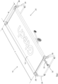
- Fig.1
- shows a perspective view of an automated massage apparatus according to the present invention;
- Fig.2
- shows a view similar to
Fig.1 but with the massage surface removed to show the underlying components; - Fig.3
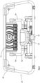
- shows an end view of the apparatus of
Fig.1 ; - Fig.4
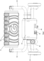
- shows a view of the motor housing and massage element, in the opposite direction of view to that of
Fig.3 ; - Fig.5
- shows a side view of the apparatus of
Fig.1 , with the massage element in a lowered, non-use position; - Fig.6
- shows a view as
Fig.4 but with the massage element in a raised in-use position; - Fig.7
- shows a perspective view of an alternative bed for use in an automated massage apparatus according to the present invention; and
- Fig.8
- shows a part of the bed of
Fig.7 . - The
automated massage apparatus 10 has amassage surface 12 and a massage element 14 (seeFigs 2-6 ). Themassage element 14, in its raised in-use position as shown inFigs.3 and6 ), can move relative to (along) themassage surface 12. - The
massage surface 12 is part of abed 20, in this embodiment a collapsible bed similar to a camp bed. Themassage surface 12 comprises a layer of material, ideally a fabric material, which is mounted upon two substantiallylinear frame members 22, the frame members being supported bylegs 24 at each end of thebed 20. Thelegs 24 each comprise a structure of trapezoidal shape, i.e. with two horizontal members joined by two inclined members, the inclined members converging towards their top. - Each end of the
frame members 22 has a connector (not seen). Each of thelegs 24 has twocorner members 26. It is arranged that eachcorner member 26 has an opening (not seen) to receive a connector whereby theframe members 22 can be connected to thelegs 24. In this embodiment the connector is releasably secured to thecorner member 26 by a latch mechanism (not shown), the latch mechanism permitting separation of theframe member 22 from thecorner member 26 for disassembly of thebed 20. - It will be understood that the detailed structure of the
bed 20 is not relevant to the present invention and any suitable bed which is able to support the user's weight, and is preferably lightweight and foldable or otherwise collapsible, could be used. It will nevertheless be understood that the relationship between thebed 20 and themassage element 14 is important, and in particular the height of thebed 20 must be appropriate to the in-use position of the massage element. - The
frame members 22,legs 24 and mountingmembers 26 together comprise the frame of thebed 20. - As most clearly seen in
Figs. 5 and 6 , the lower horizontal member of thelegs 24 are interconnected by aguide rail 30. Each end of theguide rail 30 has a respective connector which can be releasably secured to a mountingmember 32 carried by the lower horizontal member of eachleg 24. Theguide rail 30 is therefore removable from the frame of thebed 20 when desired. Though not shown in the drawings, one or both of the mountingmembers 32 preferably includes means for tensioning theguide rail 30 between thelegs 24 whereby to secure theguide rail 30 to the frame of thebed 20. One suitable arrangement could include an adjustment slot in the mounting member and a tightening knob permitting the user to secure theguide rail 30 in position. Thus, it will be recognised that it is desirable to secure theguide rail 30 in position relative to thebed 20, notwithstanding that the guide rail is removable for storage and transportation. - In this embodiment the
guide rail 30 includes arack 34. Therack 34 is engaged by a pinion 36 (seeFig. 4 ) mounted upon themotor housing 40. Themotor housing 40 contains a motor (ideally an electric motor) which drives thepinion 36 to rotate and thereby to cause themotor housing 40 to traverse along theguide rail 30 and thereby along themassage surface 12. -
Figs. 5 and 6 shows the series oflegs 38 which are mounted to theguide rail 30 and which support the guide rail, especially when the massage apparatus is in use. It is recognised that the behaviour of the rack in relation to the bed and the floor upon which the bed is resting depends to some extent upon whether the floor is a hard floor or is carpeted. Thelegs 38 are positioned to provide point bearing against the floor as themotor housing 40 passes along the bed. 20 - The
motor housing 40 includes a wheeled carriage having fourwheels 42. Thewheels 42 engage the floor and support the weight of themotor housing 40. In this embodiment therefore theguide rail 30 is not required to support any of the weight of themotor housing 40 and needs to be made sufficiently robust only to permit thepinion 36 to drive themotor housing 40 along theguide rail 30 during use. Whilst it can be expected that the force required to drive themotor housing 40 to traverse along theguide rail 30 during use might be significant, avoiding any requirement for the guide rail to support the weight of themotor housing 40 can permit a significant reduction in the strength and weight of theguide rail 30. In alternative embodiments the guide rail can be made sufficiently robust to support at least part of the weight of the motor housing if that is desired. - The
massage element 14 is mounted to themotor housing 40, and in this embodiment is in the form of a single roller. Theroller 14 is mounted upon aU-shaped beam 52 having twoarms 54, the arms supporting opposing ends of theroller 14. TheU-shaped beam 52 is pivotably mounted to themotor housing 40, and can move from a lowered non-use position ofFig.5 to a raised in-use position ofFig.6 . - To use the automated massage apparatus, the user lies upon the
massage surface 12 of thebed 20. Thebeam 52 is pivoted so as to raise theroller 14 into the fully-raised or in-use position ofFigs.3 and6 . Thepinion 36 is driven to rotate so that themotor housing 40 moves along theguide rail 30 and theroller 14 is moved along the underside of the massagingsurface 12, the speed of traverse being controllable by the user. - It will be understood that the user's body weight will depress the
massage surface 12 downwardly from the flat condition ofFig.1 . The upwards force of theroller 14 upon the underside of themassage surface 12 will act to lift themassage surface 12 locally, and thereby also lift a part of the user's body, thereby causing the desired pressure upon that part of the user's body. - Accordingly, as it passes along the
bed 20 theroller 14 is forced to move away from its fully-raised position by the contours of the user's body. Though not shown in the drawings, a torsion spring is connected to thebeam 52 to bias thebeam 52 towards its fully raised position. As theroller 14 passes along thebed 20 it is pressed upwardly against the user's body by the torsion spring, the force of the spring ensuring an approximately consistent pressure upon the user's body. The tension in the torsion spring can be adjusted by thecontrol knob 56, permitting the user to vary the force upon thebeam 52 and thereby to vary the pressure exerted by theroller 14. - The control system of the automated massage apparatus will preferably be arranged to reciprocate the
motor housing 40 along theguide rail 30, with the user able to control the portion of theguide rail 30 along which the motor housing moves (and perhaps to adjust or vary that portion during use). One suitable control system mounts a number of indicators, for example in the form of a contrasting register (similar to a barcode) upon theguide rail 30 and an emitter (for example an infrared emitter) upon themotor housing 40. The control system is able recognise the varying reflection from the register in order to determine the position of the motor housing along theguide rail 30. The configuration of the register (for example the spacing between neighbouring reflective lines) can vary along the full length of the guide rail so that the control system can recognise its position anywhere along the guide rail. - In a less desirable embodiment, indicators can be provided only adjacent to the ends of the guide rail (or the configuration of the register can vary only adjacent to the ends of the guide rail) so that the control system can detect its approach to the ends of the guide rail and can be configured to reverse direction before it reaches the ends of the guide rail. In such embodiments the
motor housing 40 will reciprocate along substantially the full length of thebed 20. - As a further safeguard, the
guide rail 30 can have end stops (or the teeth of therack 34 can terminate at the ends of the guide rail) to prevent the movement of thepinion 36 off the end of the rack 34 (and the control system can recognise the forced stoppage of the pinion and switch the direction of rotation). - In the preferred embodiments in which the control system can recognise the position of the
motor housing 40 anywhere along theguide rail 30, the control system can be configured to permit the user to set a reduced length of traverse for the motor housing. If the user wishes only to massage a selected part of his or her body (for example the lower back), the user can actuate a control switch when theroller 14 reaches the respective ends of the selected part of the body. The control system can record those positions of themotor housing 40 relative to theguide rail 30 for the duration of the massage and can subsequently automatically reverse the direction of rotation of thepinion 36 when the chosen positions are reached. In this way, theautomated massage apparatus 10 can be arranged to reciprocate theroller 14 along a selected part of the user's body, as desired. In the event that the user does not actuate the control switch during a subsequent massage the control system defaults to a condition in which the motor housing is automatically reversed only adjacent to the ends of the guide rail so that the whole length of the user's body is massaged. - It can also be arranged that the control system can adjust the pressure exerted by the massage element. As above stated, a torsion spring is connected to the
beam 52 which biases theroller 14 towards the underside of themassage surface 12. In addition to (or instead of) the user adjustment provided by thecontrol knob 56, it can be arranged that the control system includes a motor connected to the torsion spring (such that the torsion spring lies between the motor and the beam 52). The control system can therefore drive the torsion spring to move theroller 14 between its lowered non-use position (Fig.5 ) and its raised in-use position (Fig.6 ). The location of the torsion spring between the motor and thebeam 52 will permit theroller 14 to move up and down in use along the contours of the user's body as above stated. The control system can nevertheless actuate the motor to increase or decrease the force applied by the torsion spring so as to increase or decrease the pressure exerted by theroller 14. The user can if desired instruct the control system to adjust the pressure exerted during use, and/or can instruct the control system to adjust the pressure according to the position of themotor housing 40, the latter enabling an increase or decrease in the pressure exerted upon different parts of the user's body. - In this embodiment the controller for the control system is located in the
motor housing 40 and mains electrical power is communicated to the controller and to the motor(s) of the motor housing by an electrical wire (not shown). - By arranging the
massage surface 12 to be (substantially) horizontal, it is arranged that the user's body weight can directly oppose the force applied by themassage element 14, and the likelihood of strain upon other parts of the user's body is minimised. - Also, it is arranged that the length L of the bed is around 1.90 meters and the width W of the bed is around 0.6 metres. Such dimensions are expected to be able to accommodate most users, and to permit the user to lie substantially flat upon the
massage surface 12. The user will typically lie face up on the massage surface but can if desired lie face down or on his or her side. Since theroller 14 can be moved along substantially the full length of themassage surface 12, the user is able to massage almost all of his or her body, and thereby almost any chosen part of his or her body. - The
roller 14 is mounted to thearms 54 by way of bearings (not seen), so that theroller 14 is relatively freely rotatable. In this embodiment therefore theroller 14 is not driven to rotate directly and instead its rotation is determined by its frictional engagement with the underside of themassage surface 12. Theroller 14 is ideally made from a soft compressible material with a surface friction coefficient sufficient to enable free rotation when under the typical loads due to the massaging pressure so that it rotates rather than slides as it is driven across the underside of themassage surface 12. - It will be seen from
Fig.4 in particular that the surface of theroller 14 is made uneven, withmany peaks 50 separated by troughs. It is generally recognised that a massaging element should preferably have a non-planar surface so as to provide localised areas of higher pressure and lower pressure during use. - The material of the
massage surface 12 of thebed 20 is substantially uniform and is under substantially uniform tension so that the massage surface is substantially flat when not in use. The material stretches and/or deforms (downwardly) when a user lies upon the bed, the deformation at different parts of the massage surface depending upon the weight of the different parts of the user's body. The (upwards) pressure applied by theroller 14 in use will therefore vary somewhat as it traverses the user's body, depending upon the contours of the user's body and the local deformations. -
Figs. 7 and 8 show an alternative design ofbed 120 with anon-uniform massage surface 112. Because themassage surface 112 is not uniform the local deformations in use do not depend only upon the weight of the particular parts of the user's body and the deformations can be exaggerated and/or diminished in order to enhance a massage. - The first difference of the alternative design of
bed 120 is that the material of themassage surface 112 is extended at afirst region 60 of thebed 120. It is intended that the user will lie upon thebed 120 with his or her feet in theregion 60. It is recognised that the lower legs are not particularly heavy and together with the proximity to the surrounding frame of thebed 120, a substantially uniform massage surface will usually deform significantly less adjacent the user's feet than in other areas. In this alternative embodiment the material (which may be canvas for example) which forms themassage surface 120 includes darts and pleats in theregion 60 so that when not in use themassage surface 120 in theregion 60 lies somewhat below the remainder of the massage surface (perhaps around 12 cm lower for example). In use therefore, the user can lie with his or her feet in the local depression provided at theregion 60. - The local depression at the
region 60 has two benefits when the massage apparatus is in use with the user lying upon his or her back. The primary benefit is that the user's feet are lowered and the pressure upon a user's heels is reduced; this relieves tension in the heel to calf region of the lower leg. The secondary benefit is that the user's lower legs rest closer to the floor and the pressure which is applied to the lower legs by the massage element is increased; this give an enhanced (deeper) massage to that area of the user's body. - The second difference is that the
massage surface 120 is locally reinforced at asecond region 62. Thesecond region 62 includes a double-layer of material. The double-layer is optional and provides some localised additional support. The major benefit of the double-layer, however, is that it permits a lattice cord 64 (shown in dashed outline inFig.8 ) to pass across thebed 120 between the two layers of material. Thelattice cord 64 can be tensioned to allow users with a large range of weights and body shapes to use a massage apparatus incorporating thebed 120. - The
second region 62 is located at the centre of thebed 120 and is therefore where the user's buttocks will typically rest. The additional localised support provided in thesecond region 62 results in the deformation (depression) caused by this relatively heavy part of the user's body to be reduced. The deformation at this region of themassage surface 112 is also increased because it is the furthest spaced from the frame of thebed 120. The inventors have found that providing additional localised support adjacent to the buttocks of some users enhances the massage provided to the user's lower back. - Whilst the double-layer material in the
second region 62 of themassage surface 112 provides a small degree of additional support for all users, thelattice cord 64 enables the degree of additional support to be temporary and adjustable to suit the user. The ends of thelattice cord 64 pass through and are retained by acleat 66 attached to the side of thebed 120; the user can pull one end of thecord 64 by way of atoggle 68 to increase the tension in the cord (and can release thecleat 66 to reduce the tension in the cord) and thereby to adjust the degree of additional support provided in thesecond region 62. - It will be understood that the temporary additional support in the second region could alternatively be provided by way of supporting straps, webbing or netting above or below the massage surface.
- Whilst the
bed 120 is shown without a guide rail and without a motor housing and massage element, it will be understood that thebed 120 could include mounting members for a guide rail (such as the mountingmembers 32 for aguide rail 30 of the bed 20) to provide an automated massage apparatus similar to that shown in the first embodiment. - When the
automated massage apparatus 10 is not in use it can be disassembled for storage and/or transportation. Thepinion 36 is held against therack 34 by a series of rollers 48 (one of which can be seen inFig.4 ). Such an arrangement allows themotor housing 40 to be lifted from theguide rail 30 and separated from the bed 20 (120). It is arranged that themotor housing 40 can move very close to thelegs 24 whereby to permit the motor housing to be grasped from an end of thebed 20 and lifted between the horizontal members of theleg 24. The tension in theguide rail 30 can then be released and theguide rail 30 removed from thelegs 24 and separated from the other components. Theframe members 22, together with themassage surface 12, can then be released from theend legs 24, whereupon theframe members 22 andmassage surface 12 can be rolled up. Thelegs 24 can be stored as they are, or can be made from separable parts for further disassembly, in known fashion. - It is expected that the
automated massage apparatus 10 will be provided with a remote control unit to permit the user to operate the apparatus whilst lying on thebed 20. The remote control unit can communicate with the controller of the control system by wire or wirelessly. The remote control apparatus can be used to instruct the control system to move themassage element 14 between its lowered and raised positions at the start and end of a massage, and/or to adjust the speed of traverse of the massage element along the bed, and/or to adjust the pressure exerted by the massage element. In the preferred embodiments described the remote control unit can also be used to set the reversing positions for themotor housing 40 in the event that the user wishes to massage only a selected part of his or her body.
Claims (15)
- A portable automated massage apparatus (10) having a massage surface (12; 112) and a massage element (14) which can move relative to the massage surface, the massage surface being provided by a substantially horizontal bed (20; 120), the bed including a substantially rigid frame to which the massage surface is mounted, the frame including a set of legs (24) which hold the massage surface (12; 112) above the floor in use,the massage element (14) is mounted to a motor housing (40),the motor housing (40) includes a wheeled carriage, the wheels of the carriage being located to engage the floor during use,the bed has a guide rail (30) for the motor housing, the motor housing being removable from the guide rail,and the bed is assembled from separable components which enable disassembly of the bed.
- The automated massage apparatus of claim 1 in which the massage surface (12; 112) is flexible and resilient.
- The automated massage apparatus of claim 1 or claim 2 in which the massage surface (112) is non-uniform and includes localised deformations (60).
- The automated massage apparatus of any of claims 1-3 in which the massage surface (112) is non-uniform and includes localised additional support (62).
- The automated massage apparatus of any of claims 1-4 in which the massage element (14) comprises a roller which is driven to traverse the massage surface (12; 112).
- The automated massage apparatus of claim 5 in which the roller can traverse substantially the full length of the massage surface.
- The automated massage apparatus of claim 5 or claim 6 in which the roller (14) is mounted upon bearings to rotate passively due to its frictional engagement with the massage surface (12; 112).
- The automated massage apparatus of any of claims 1-7 in which the surface of the massage element (14) is uneven.
- The automated massage apparatus of any of claims 1-8 in which the pressure exerted by the massage element (14) upon the underside of the massage surface (12; 112) is adjustable.
- The automated massage apparatus of any one of claims 1-9 in which the massage element (14) is movably mounted to the motor housing.
- The automated massage apparatus of claim 10 in which the massage element (14) is movable in the vertical direction relative to the motor housing (40).
- The automated massage apparatus of any one of claims 1-11 in which the guide rail (30) has a rack (34) and the motor housing (40) has a pinion (36).
- The automated massage apparatus of any one of claims 1-12 having a controller for the massage element (14), the guide rail (30) having at least one indicator and the motor housing (40) having a detector by which the controller can identify the position of the motor housing relative to the guide rail.
- The automated massage apparatus according to claim 13 in which the guide rail has respective indicators adjacent to each end of the guide rail.
- The automated massage apparatus of any of claims 1-14 in which the massage surface is at least approximately 1.9 metres long and at least approximately 0.6 metres wide.
Applications Claiming Priority (2)
| Application Number | Priority Date | Filing Date | Title |
|---|---|---|---|
| GBGB1803254.0A GB201803254D0 (en) | 2018-02-28 | 2018-02-28 | Automated massage apparatus |
| PCT/EP2019/055082 WO2019166597A1 (en) | 2018-02-28 | 2019-02-28 | Automated massage apparatus |
Publications (2)
| Publication Number | Publication Date |
|---|---|
| EP3758663A1 EP3758663A1 (en) | 2021-01-06 |
| EP3758663B1 true EP3758663B1 (en) | 2025-03-26 |
Family
ID=61903439
Family Applications (1)
| Application Number | Title | Priority Date | Filing Date |
|---|---|---|---|
| EP19709419.6A Active EP3758663B1 (en) | 2018-02-28 | 2019-02-28 | Automated massage apparatus |
Country Status (7)
| Country | Link |
|---|---|
| US (1) | US12005020B2 (en) |
| EP (1) | EP3758663B1 (en) |
| JP (1) | JP7309107B2 (en) |
| CN (1) | CN111727028A (en) |
| GB (2) | GB201803254D0 (en) |
| TW (1) | TWI801511B (en) |
| WO (1) | WO2019166597A1 (en) |
Families Citing this family (4)
| Publication number | Priority date | Publication date | Assignee | Title |
|---|---|---|---|---|
| EP3812142A1 (en) | 2019-10-23 | 2021-04-28 | Carl Zeiss Vision International GmbH | Method for producing a spectacle lens and a product comprising a spectacle lens |
| KR102601265B1 (en) * | 2021-03-09 | 2023-11-13 | 이성희 | Spine massage equipment |
| CN115645269B (en) * | 2022-12-09 | 2023-03-14 | 杭州大力神医疗器械有限公司 | Lumbar vertebra physiotherapy rehabilitation therapeutic instrument |
| WO2025107066A1 (en) * | 2023-11-21 | 2025-05-30 | 1824067 Ontario Inc. | Pressure sore prevention bed |
Family Cites Families (22)
| Publication number | Priority date | Publication date | Assignee | Title |
|---|---|---|---|---|
| EP0060934A1 (en) * | 1981-01-06 | 1982-09-29 | Combi Co., Ltd. | Roller-type massage apparatus |
| JPS57176228A (en) | 1981-04-20 | 1982-10-29 | Mitsubishi Rayon Co | Production of slub yarn |
| JPS6128620Y2 (en) * | 1981-05-02 | 1986-08-25 | ||
| US4656998A (en) * | 1984-10-05 | 1987-04-14 | France Bed Co., Ltd. | Foldable massage bed with reciprocating rollers |
| US4886051A (en) * | 1988-06-27 | 1989-12-12 | White Francis E | Massaging bed |
| US5020518A (en) * | 1990-02-09 | 1991-06-04 | Integrity Health Systems Corporation | Travelling roller massage apparatus |
| JPH078529A (en) * | 1993-06-25 | 1995-01-13 | Matsushita Electric Works Ltd | Massage apparatus |
| JPH0833687A (en) * | 1994-05-17 | 1996-02-06 | Dainichi Kogyo Giken:Kk | Bed type massage machine |
| JP2717776B2 (en) * | 1995-02-10 | 1998-02-25 | 株式会社日本メディックス | Roller massage machine |
| JP4182383B2 (en) * | 1999-07-29 | 2008-11-19 | 繁夫 高村 | Unit type roller driving device for electric roller massager and electric roller massager provided with the same |
| US7066898B2 (en) * | 2000-06-30 | 2006-06-27 | Omron Corporation | Vibrator, vibration unit, and vibrator control method |
| CA2361896C (en) * | 2000-11-15 | 2009-08-04 | Ceragem International, Inc. | Mat for hot compress and acupressure mounted with new type hyperthermo-radiative apparatus |
| KR100503032B1 (en) * | 2002-09-16 | 2005-07-22 | 천용호 | Bed for massage |
| US20040260215A1 (en) | 2003-06-23 | 2004-12-23 | Hakjin Kim | Human body massaging method and apparatus |
| US7052476B2 (en) | 2003-07-18 | 2006-05-30 | Hakjin Kim | Lie-down massager |
| US20070185421A1 (en) * | 2006-02-03 | 2007-08-09 | Dong-Her Wu | Folding bed message mattress with idler wheel |
| CN102579224B (en) * | 2012-03-19 | 2013-11-06 | 安徽久工科技实业有限责任公司 | Foldable massage bed with roller groups |
| CN202537931U (en) * | 2012-03-19 | 2012-11-21 | 安徽久工科技实业有限责任公司 | Folding type roller unit massage bed |
| WO2014105042A1 (en) * | 2012-12-28 | 2014-07-03 | Tempur-Pedic Management, Llc | Massage cushion assemblies |
| CN203802768U (en) * | 2014-03-11 | 2014-09-03 | 宁波慕瑞斯健康科技有限公司 | Massage mechanism |
| CN105395348B (en) * | 2014-09-11 | 2018-12-07 | 喜来健株式会社 | Two column ceramic structure of self |
| CN205126721U (en) * | 2015-09-02 | 2016-04-06 | 张富穗 | multifunctional shiatsu massage bed |
-
2018
- 2018-02-28 GB GBGB1803254.0A patent/GB201803254D0/en not_active Ceased
-
2019
- 2019-02-28 US US16/975,123 patent/US12005020B2/en active Active
- 2019-02-28 GB GB1902744.0A patent/GB2572483B/en active Active
- 2019-02-28 CN CN201980013748.6A patent/CN111727028A/en active Pending
- 2019-02-28 WO PCT/EP2019/055082 patent/WO2019166597A1/en not_active Ceased
- 2019-02-28 EP EP19709419.6A patent/EP3758663B1/en active Active
- 2019-02-28 JP JP2020544239A patent/JP7309107B2/en active Active
- 2019-03-04 TW TW108107118A patent/TWI801511B/en active
Also Published As
| Publication number | Publication date |
|---|---|
| US20210085556A1 (en) | 2021-03-25 |
| JP2021514712A (en) | 2021-06-17 |
| GB201803254D0 (en) | 2018-04-11 |
| JP7309107B2 (en) | 2023-07-18 |
| TW201936154A (en) | 2019-09-16 |
| WO2019166597A1 (en) | 2019-09-06 |
| EP3758663A1 (en) | 2021-01-06 |
| US12005020B2 (en) | 2024-06-11 |
| TWI801511B (en) | 2023-05-11 |
| CN111727028A (en) | 2020-09-29 |
| GB2572483A (en) | 2019-10-02 |
| GB2572483B (en) | 2020-03-25 |
| GB201902744D0 (en) | 2019-04-17 |
Similar Documents
| Publication | Publication Date | Title |
|---|---|---|
| US12005020B2 (en) | Automated massage apparatus | |
| US20110009903A1 (en) | Therapy mat table with adjustable portion | |
| US7931574B2 (en) | Apparatus for autonomously performing physiotherapic exercises | |
| KR101150304B1 (en) | Massage chair | |
| US11998504B2 (en) | Chair including percussive massage therapy | |
| KR101783017B1 (en) | Laser thermal massage bed | |
| US20210007927A1 (en) | Full body wrap massage chair | |
| KR102710091B1 (en) | Massage apparatus having rotatable arm massage unit | |
| JP7509346B2 (en) | Chair-type lumbar traction device | |
| KR20240144029A (en) | Massage apparatus having rotatable arm massage unit | |
| JP5116318B2 (en) | Chair massage machine | |
| KR101632597B1 (en) | Apparatus for posture transforming and wheelchair including the same | |
| US20220362090A1 (en) | A multifunctional apparatus | |
| JPH1014963A (en) | Pulling apparatus for chiropractic | |
| KR102907974B1 (en) | Massage Apparatus providing Combination Standing mode Method for controlling massage apparatus | |
| JP3056805U (en) | Nursing chair device | |
| KR20240027210A (en) | Bed type massage device | |
| US20170231858A1 (en) | Limb treatment device and method for treatment of vascular and/or neuropathic disorders | |
| JP2016101477A (en) | Massage machine | |
| JPH0833687A (en) | Bed type massage machine |
Legal Events
| Date | Code | Title | Description |
|---|---|---|---|
| STAA | Information on the status of an ep patent application or granted ep patent |
Free format text: STATUS: UNKNOWN |
|
| STAA | Information on the status of an ep patent application or granted ep patent |
Free format text: STATUS: THE INTERNATIONAL PUBLICATION HAS BEEN MADE |
|
| PUAI | Public reference made under article 153(3) epc to a published international application that has entered the european phase |
Free format text: ORIGINAL CODE: 0009012 |
|
| STAA | Information on the status of an ep patent application or granted ep patent |
Free format text: STATUS: REQUEST FOR EXAMINATION WAS MADE |
|
| 17P | Request for examination filed |
Effective date: 20200817 |
|
| AK | Designated contracting states |
Kind code of ref document: A1 Designated state(s): AL AT BE BG CH CY CZ DE DK EE ES FI FR GB GR HR HU IE IS IT LI LT LU LV MC MK MT NL NO PL PT RO RS SE SI SK SM TR |
|
| AX | Request for extension of the european patent |
Extension state: BA ME |
|
| DAV | Request for validation of the european patent (deleted) | ||
| DAX | Request for extension of the european patent (deleted) | ||
| STAA | Information on the status of an ep patent application or granted ep patent |
Free format text: STATUS: EXAMINATION IS IN PROGRESS |
|
| 17Q | First examination report despatched |
Effective date: 20231127 |
|
| GRAP | Despatch of communication of intention to grant a patent |
Free format text: ORIGINAL CODE: EPIDOSNIGR1 |
|
| STAA | Information on the status of an ep patent application or granted ep patent |
Free format text: STATUS: GRANT OF PATENT IS INTENDED |
|
| INTG | Intention to grant announced |
Effective date: 20241112 |
|
| GRAS | Grant fee paid |
Free format text: ORIGINAL CODE: EPIDOSNIGR3 |
|
| GRAA | (expected) grant |
Free format text: ORIGINAL CODE: 0009210 |
|
| STAA | Information on the status of an ep patent application or granted ep patent |
Free format text: STATUS: THE PATENT HAS BEEN GRANTED |
|
| AK | Designated contracting states |
Kind code of ref document: B1 Designated state(s): AL AT BE BG CH CY CZ DE DK EE ES FI FR GR HR HU IE IS IT LI LT LU LV MC MK MT NL NO PL PT RO RS SE SI SK SM TR |
|
| RBV | Designated contracting states (corrected) |
Designated state(s): AL AT BE BG CH CY CZ DE DK EE ES FI FR GR HR HU IE IS IT LI LT LU LV MC MK MT NL NO PL PT RO RS SE SI SK SM TR |
|
| REG | Reference to a national code |
Ref country code: CH Ref legal event code: EP |
|
| REG | Reference to a national code |
Ref country code: DE Ref legal event code: R096 Ref document number: 602019067739 Country of ref document: DE |
|
| REG | Reference to a national code |
Ref country code: IE Ref legal event code: FG4D |
|
| PG25 | Lapsed in a contracting state [announced via postgrant information from national office to epo] |
Ref country code: RS Free format text: LAPSE BECAUSE OF FAILURE TO SUBMIT A TRANSLATION OF THE DESCRIPTION OR TO PAY THE FEE WITHIN THE PRESCRIBED TIME-LIMIT Effective date: 20250626 |
|
| PG25 | Lapsed in a contracting state [announced via postgrant information from national office to epo] |
Ref country code: FI Free format text: LAPSE BECAUSE OF FAILURE TO SUBMIT A TRANSLATION OF THE DESCRIPTION OR TO PAY THE FEE WITHIN THE PRESCRIBED TIME-LIMIT Effective date: 20250326 |
|
| REG | Reference to a national code |
Ref country code: LT Ref legal event code: MG9D |
|
| PG25 | Lapsed in a contracting state [announced via postgrant information from national office to epo] |
Ref country code: NO Free format text: LAPSE BECAUSE OF FAILURE TO SUBMIT A TRANSLATION OF THE DESCRIPTION OR TO PAY THE FEE WITHIN THE PRESCRIBED TIME-LIMIT Effective date: 20250626 |
|
| PG25 | Lapsed in a contracting state [announced via postgrant information from national office to epo] |
Ref country code: HR Free format text: LAPSE BECAUSE OF FAILURE TO SUBMIT A TRANSLATION OF THE DESCRIPTION OR TO PAY THE FEE WITHIN THE PRESCRIBED TIME-LIMIT Effective date: 20250326 |
|
| PG25 | Lapsed in a contracting state [announced via postgrant information from national office to epo] |
Ref country code: LV Free format text: LAPSE BECAUSE OF FAILURE TO SUBMIT A TRANSLATION OF THE DESCRIPTION OR TO PAY THE FEE WITHIN THE PRESCRIBED TIME-LIMIT Effective date: 20250326 |
|
| PG25 | Lapsed in a contracting state [announced via postgrant information from national office to epo] |
Ref country code: GR Free format text: LAPSE BECAUSE OF FAILURE TO SUBMIT A TRANSLATION OF THE DESCRIPTION OR TO PAY THE FEE WITHIN THE PRESCRIBED TIME-LIMIT Effective date: 20250627 Ref country code: BG Free format text: LAPSE BECAUSE OF FAILURE TO SUBMIT A TRANSLATION OF THE DESCRIPTION OR TO PAY THE FEE WITHIN THE PRESCRIBED TIME-LIMIT Effective date: 20250326 |
|
| REG | Reference to a national code |
Ref country code: NL Ref legal event code: MP Effective date: 20250326 |
|
| PG25 | Lapsed in a contracting state [announced via postgrant information from national office to epo] |
Ref country code: NL Free format text: LAPSE BECAUSE OF FAILURE TO SUBMIT A TRANSLATION OF THE DESCRIPTION OR TO PAY THE FEE WITHIN THE PRESCRIBED TIME-LIMIT Effective date: 20250326 |
|
| PG25 | Lapsed in a contracting state [announced via postgrant information from national office to epo] |
Ref country code: SE Free format text: LAPSE BECAUSE OF FAILURE TO SUBMIT A TRANSLATION OF THE DESCRIPTION OR TO PAY THE FEE WITHIN THE PRESCRIBED TIME-LIMIT Effective date: 20250326 |
|
| REG | Reference to a national code |
Ref country code: AT Ref legal event code: MK05 Ref document number: 1778342 Country of ref document: AT Kind code of ref document: T Effective date: 20250326 |
|
| PG25 | Lapsed in a contracting state [announced via postgrant information from national office to epo] |
Ref country code: SM Free format text: LAPSE BECAUSE OF FAILURE TO SUBMIT A TRANSLATION OF THE DESCRIPTION OR TO PAY THE FEE WITHIN THE PRESCRIBED TIME-LIMIT Effective date: 20250326 |
|
| PG25 | Lapsed in a contracting state [announced via postgrant information from national office to epo] |
Ref country code: PT Free format text: LAPSE BECAUSE OF FAILURE TO SUBMIT A TRANSLATION OF THE DESCRIPTION OR TO PAY THE FEE WITHIN THE PRESCRIBED TIME-LIMIT Effective date: 20250728 Ref country code: ES Free format text: LAPSE BECAUSE OF FAILURE TO SUBMIT A TRANSLATION OF THE DESCRIPTION OR TO PAY THE FEE WITHIN THE PRESCRIBED TIME-LIMIT Effective date: 20250326 |
|
| PG25 | Lapsed in a contracting state [announced via postgrant information from national office to epo] |
Ref country code: PL Free format text: LAPSE BECAUSE OF FAILURE TO SUBMIT A TRANSLATION OF THE DESCRIPTION OR TO PAY THE FEE WITHIN THE PRESCRIBED TIME-LIMIT Effective date: 20250326 Ref country code: IT Free format text: LAPSE BECAUSE OF FAILURE TO SUBMIT A TRANSLATION OF THE DESCRIPTION OR TO PAY THE FEE WITHIN THE PRESCRIBED TIME-LIMIT Effective date: 20250326 |
|
| PG25 | Lapsed in a contracting state [announced via postgrant information from national office to epo] |
Ref country code: AT Free format text: LAPSE BECAUSE OF FAILURE TO SUBMIT A TRANSLATION OF THE DESCRIPTION OR TO PAY THE FEE WITHIN THE PRESCRIBED TIME-LIMIT Effective date: 20250326 |
|
| PG25 | Lapsed in a contracting state [announced via postgrant information from national office to epo] |
Ref country code: EE Free format text: LAPSE BECAUSE OF FAILURE TO SUBMIT A TRANSLATION OF THE DESCRIPTION OR TO PAY THE FEE WITHIN THE PRESCRIBED TIME-LIMIT Effective date: 20250326 |
|
| PG25 | Lapsed in a contracting state [announced via postgrant information from national office to epo] |
Ref country code: RO Free format text: LAPSE BECAUSE OF FAILURE TO SUBMIT A TRANSLATION OF THE DESCRIPTION OR TO PAY THE FEE WITHIN THE PRESCRIBED TIME-LIMIT Effective date: 20250326 |
|
| PG25 | Lapsed in a contracting state [announced via postgrant information from national office to epo] |
Ref country code: SK Free format text: LAPSE BECAUSE OF FAILURE TO SUBMIT A TRANSLATION OF THE DESCRIPTION OR TO PAY THE FEE WITHIN THE PRESCRIBED TIME-LIMIT Effective date: 20250326 |
|
| PG25 | Lapsed in a contracting state [announced via postgrant information from national office to epo] |
Ref country code: IS Free format text: LAPSE BECAUSE OF FAILURE TO SUBMIT A TRANSLATION OF THE DESCRIPTION OR TO PAY THE FEE WITHIN THE PRESCRIBED TIME-LIMIT Effective date: 20250726 |
|
| REG | Reference to a national code |
Ref country code: DE Ref legal event code: R097 Ref document number: 602019067739 Country of ref document: DE |
|
| PG25 | Lapsed in a contracting state [announced via postgrant information from national office to epo] |
Ref country code: DK Free format text: LAPSE BECAUSE OF FAILURE TO SUBMIT A TRANSLATION OF THE DESCRIPTION OR TO PAY THE FEE WITHIN THE PRESCRIBED TIME-LIMIT Effective date: 20250326 |
|
| PG25 | Lapsed in a contracting state [announced via postgrant information from national office to epo] |
Ref country code: CZ Free format text: LAPSE BECAUSE OF FAILURE TO SUBMIT A TRANSLATION OF THE DESCRIPTION OR TO PAY THE FEE WITHIN THE PRESCRIBED TIME-LIMIT Effective date: 20250326 |
|
| PLBE | No opposition filed within time limit |
Free format text: ORIGINAL CODE: 0009261 |
|
| STAA | Information on the status of an ep patent application or granted ep patent |
Free format text: STATUS: NO OPPOSITION FILED WITHIN TIME LIMIT |
|
| REG | Reference to a national code |
Ref country code: CH Ref legal event code: L10 Free format text: ST27 STATUS EVENT CODE: U-0-0-L10-L00 (AS PROVIDED BY THE NATIONAL OFFICE) Effective date: 20260211 |
|
| 26N | No opposition filed |
Effective date: 20260105 |
|
| PGFP | Annual fee paid to national office [announced via postgrant information from national office to epo] |
Ref country code: DE Payment date: 20260107 Year of fee payment: 8 Ref country code: IE Payment date: 20260224 Year of fee payment: 8 |
|
| PGFP | Annual fee paid to national office [announced via postgrant information from national office to epo] |
Ref country code: BE Payment date: 20260226 Year of fee payment: 8 |
|
| PGFP | Annual fee paid to national office [announced via postgrant information from national office to epo] |
Ref country code: FR Payment date: 20260227 Year of fee payment: 8 |