EP3758470B1 - Multi-piece hydroponic tower with hinged tower face - Google Patents
Multi-piece hydroponic tower with hinged tower face Download PDFInfo
- Publication number
- EP3758470B1 EP3758470B1 EP19760378.0A EP19760378A EP3758470B1 EP 3758470 B1 EP3758470 B1 EP 3758470B1 EP 19760378 A EP19760378 A EP 19760378A EP 3758470 B1 EP3758470 B1 EP 3758470B1
- Authority
- EP
- European Patent Office
- Prior art keywords
- tower
- cavity
- face plate
- side wall
- wall
- Prior art date
- Legal status (The legal status is an assumption and is not a legal conclusion. Google has not performed a legal analysis and makes no representation as to the accuracy of the status listed.)
- Active
Links
Images


Classifications
-
- A—HUMAN NECESSITIES
- A01—AGRICULTURE; FORESTRY; ANIMAL HUSBANDRY; HUNTING; TRAPPING; FISHING
- A01G—HORTICULTURE; CULTIVATION OF VEGETABLES, FLOWERS, RICE, FRUIT, VINES, HOPS OR SEAWEED; FORESTRY; WATERING
- A01G31/00—Soilless cultivation, e.g. hydroponics
- A01G31/02—Special apparatus therefor
- A01G31/04—Hydroponic culture on conveyors
- A01G31/045—Hydroponic culture on conveyors with containers guided along a rail
-
- A—HUMAN NECESSITIES
- A01—AGRICULTURE; FORESTRY; ANIMAL HUSBANDRY; HUNTING; TRAPPING; FISHING
- A01G—HORTICULTURE; CULTIVATION OF VEGETABLES, FLOWERS, RICE, FRUIT, VINES, HOPS OR SEAWEED; FORESTRY; WATERING
- A01G31/00—Soilless cultivation, e.g. hydroponics
- A01G31/02—Special apparatus therefor
- A01G31/06—Hydroponic culture on racks or in stacked containers
-
- E—FIXED CONSTRUCTIONS
- E05—LOCKS; KEYS; WINDOW OR DOOR FITTINGS; SAFES
- E05D—HINGES OR SUSPENSION DEVICES FOR DOORS, WINDOWS OR WINGS
- E05D1/00—Pinless hinges; Substitutes for hinges
-
- E—FIXED CONSTRUCTIONS
- E05—LOCKS; KEYS; WINDOW OR DOOR FITTINGS; SAFES
- E05D—HINGES OR SUSPENSION DEVICES FOR DOORS, WINDOWS OR WINGS
- E05D9/00—Flaps or sleeves specially designed for making from particular material, e.g. hoop-iron, sheet metal, plastics
- E05D9/005—Flaps or sleeves specially designed for making from particular material, e.g. hoop-iron, sheet metal, plastics from plastics
-
- F—MECHANICAL ENGINEERING; LIGHTING; HEATING; WEAPONS; BLASTING
- F16—ENGINEERING ELEMENTS AND UNITS; GENERAL MEASURES FOR PRODUCING AND MAINTAINING EFFECTIVE FUNCTIONING OF MACHINES OR INSTALLATIONS; THERMAL INSULATION IN GENERAL
- F16B—DEVICES FOR FASTENING OR SECURING CONSTRUCTIONAL ELEMENTS OR MACHINE PARTS TOGETHER, e.g. NAILS, BOLTS, CIRCLIPS, CLAMPS, CLIPS OR WEDGES; JOINTS OR JOINTING
- F16B7/00—Connections of rods or tubes, e.g. of non-circular section, mutually, including resilient connections
- F16B7/04—Clamping or clipping connections
- F16B7/0433—Clamping or clipping connections for rods or tubes being in parallel relationship
-
- E—FIXED CONSTRUCTIONS
- E05—LOCKS; KEYS; WINDOW OR DOOR FITTINGS; SAFES
- E05Y—INDEXING SCHEME ASSOCIATED WITH SUBCLASSES E05D AND E05F, RELATING TO CONSTRUCTION ELEMENTS, ELECTRIC CONTROL, POWER SUPPLY, POWER SIGNAL OR TRANSMISSION, USER INTERFACES, MOUNTING OR COUPLING, DETAILS, ACCESSORIES, AUXILIARY OPERATIONS NOT OTHERWISE PROVIDED FOR, APPLICATION THEREOF
- E05Y2999/00—Subject-matter not otherwise provided for in this subclass
-
- Y—GENERAL TAGGING OF NEW TECHNOLOGICAL DEVELOPMENTS; GENERAL TAGGING OF CROSS-SECTIONAL TECHNOLOGIES SPANNING OVER SEVERAL SECTIONS OF THE IPC; TECHNICAL SUBJECTS COVERED BY FORMER USPC CROSS-REFERENCE ART COLLECTIONS [XRACs] AND DIGESTS
- Y02—TECHNOLOGIES OR APPLICATIONS FOR MITIGATION OR ADAPTATION AGAINST CLIMATE CHANGE
- Y02P—CLIMATE CHANGE MITIGATION TECHNOLOGIES IN THE PRODUCTION OR PROCESSING OF GOODS
- Y02P60/00—Technologies relating to agriculture, livestock or agroalimentary industries
- Y02P60/20—Reduction of greenhouse gas [GHG] emissions in agriculture, e.g. CO2
- Y02P60/21—Dinitrogen oxide [N2O], e.g. using aquaponics, hydroponics or efficiency measures
Definitions
- the present invention relates generally to hydroponic growing systems and, more particularly, to a hydroponic tower that provides increased planting consistency, decreased manufacturing time and cost, and improved tower characteristics (e.g., strength, ease of cleaning, efficiency of use, etc.).
- Hydroponics is a soilless growing technique in which plants are grown using a liquid solution of water and nutrients.
- the roots of the plants are typically maintained in a fibrous or granular material, often comprised of plastic, and fed via a wick, drip, nutrient film, or other nutrient delivery system.
- Hydroponic growing systems are often established within indoor facilities, thus allowing them to be located in or near population centers.
- This approach also provides exceptional climate control (i.e., temperature, humidity, air flow, CO 2 concentration, light wavelength, intensity and duration, etc.) as well as improved pest and disease control, thus allowing an indoor hydroponic farm to succeed in a region in which the outside environment and/or the soil conditions are inhospitable to the use of conventional farming techniques.
- hydroponic and other soilless growing techniques can yield extremely high plant densities, especially in those instances in which either horizontal stacking systems or vertical growth towers are used.
- WO2017109279 (A1 ) relates to a plant cultivation apparatus comprising a cultivation unit that has at least a vertical cultivation device for holding plants to be cultivated and a plant growth arrangement for treating the plants.
- An elongated framework of the cultivation device is a module structured composition consisting at least of a bottom element, a top element and/or an intermediate element and elongated wall elements with holes and/or sockets, the elements comprising fastening means for coupling of the elements removably with each other on a quick release principal.
- CN204616518U relates to a vertical type cultivation ware containing a hollow tube and a locating part.
- a multi-piece hydroponic tower comprised of (i) a tower body that defines a first tower cavity, where the first tower cavity is configured to provide a passageway for a water/nutrient mix, and where a first edge portion of the tower body includes a first tower body hinge member; (ii) a first tower face plate, where an edge portion of the first tower face plate includes a first face plate hinge member, where the first tower face plate is hingeably coupled to the tower body via the first tower body hinge member and the first face plate hinge member, where the first tower face plate is positionable relative to the tower body in at least a first tower cavity closed position and a first tower cavity open position, and where the first tower face plate includes a first plurality of plant container cut-outs configured to accept a first plurality of plant containers; and (iii) a first fastener configured to temporarily latch the first tower face plate to the tower body when the first tower face plate is
- the first fastener may be comprised of a first plurality of fasteners.
- the first fastener may be comprised of a first snap-fit fastener.
- the tower body and the first tower face plate may be fabricated from plastic (e.g., polyethylene, polypropylene, polyvinyl chloride, polytetrafluoroethylene, and acrylonitrile butadiene styrene, etc.) and may be white.
- the multi-piece hydroponic tower may be a dual-sided hydroponic tower, where the tower body defines a first tower cavity and a second tower cavity, where the first body hinge member of the first edge portion of the tower body corresponds to the first tower cavity, and where the tower body is further comprised of a second tower body hinge member corresponding to a second edge portion, the second tower body hinge member of the second edge portion of the tower body corresponding to the second tower cavity.
- the dual-sided hydroponic tower includes (i) a second tower face plate, where an edge portion of the second tower face plate includes a second face plate hinge member, where the second tower face plate is hingeably coupled to the tower body via the second tower body hinge member and the second face plate hinge member, where the second tower face plate is positionable relative to the tower body in at least a second tower cavity closed position and a second tower cavity open position, and where the second tower face plate includes a second plurality of plant container cut-outs configured to accept a second plurality of plant containers; and (ii) a second fastener configured to temporarily latch the second tower face plate to the tower body when the second tower face plate is in the second tower cavity closed position.
- the second fastener may be comprised of a second plurality of fasteners.
- the second fastener may be comprised of a second snap-fit fastener.
- the first tower cavity may be comprised of a first side wall, a second side wall and a first rear cavity wall, where the first side wall flares out relative to the first rear cavity wall when the first tower face plate is positioned in the first tower cavity open position, and where the second side wall flares out relative to the first rear cavity wall when the first tower face plate is positioned in the first tower cavity open position; and (ii) the second tower cavity may be comprised of a third side wall, a fourth side wall and a second rear cavity wall, where the third side wall flares out relative to the second rear cavity wall when the second tower face plate is positioned in the second tower cavity open position, and where the fourth side wall flares out relative to the second rear cavity wall when the second tower face plate is positioned in the second tower cavity open position.
- the first side wall is at an angle of approximately 100 degrees relative to the first rear cavity wall when the first tower face plate is positioned in the first tower cavity open position;
- the second side wall is at an angle of approximately 100 degrees relative to the first rear cavity wall when the first tower face plate is positioned in the first tower cavity open position;
- the third side wall is at an angle of approximately 100 degrees relative to the second rear cavity wall when the second tower face plate is positioned in the second tower cavity open position;
- the fourth side wall is at an angle of approximately 100 degrees relative to the second rear cavity wall when the second tower face plate is positioned in the second tower cavity open position.
- first side wall is approximately perpendicular to the first rear cavity wall when the first tower face plate is positioned in the first tower cavity closed position;
- second side wall is approximately perpendicular to the first rear cavity wall when the first tower face plate is positioned in the first tower cavity closed position;
- third side wall is approximately perpendicular to the second rear cavity wall when the second tower face plate is positioned in the second tower cavity closed position;
- fourth side wall is approximately perpendicular to the second rear cavity wall when the second tower face plate is positioned in the second tower cavity closed position.
- a first strain relief feature may be positioned at a first junction, where the first junction is formed between the first side wall and the first rear cavity wall; a second strain relief feature may be positioned at a second junction, where the second junction is formed between the second side wall and the first rear cavity wall; a third strain relief feature may be positioned at a third junction, where the third junction is formed between the first side wall and the second side wall; a fourth strain relief feature may be positioned at a fourth junction, where the fourth junction is formed between the third side wall and the second rear cavity wall; a fifth strain relief feature may be positioned at a fifth junction, where the fifth junction is formed between the fourth side wall and the second rear cavity wall; and a sixth strain relief feature may be positioned at a sixth junction, where the sixth junction is formed between the third side wall and the fourth side wall.
- the hydroponic tower may include (i) a first V-shaped groove running along the length of a first side of the tower body, where the first V-shaped groove is centered between the first tower cavity and the second tower cavity; and (ii) a second V-shaped groove running along the length of a second side of the tower body, where the second V-shaped groove is centered between the first tower cavity and the second tower cavity.
- first V-shaped groove may be formed from a first side wall portion corresponding to the first tower cavity and a second side wall portion corresponding to the second tower cavity
- second V-shaped groove may be formed from a third side wall portion corresponding to the first tower cavity and a fourth side wall portion corresponding to the second tower cavity
- a first strain relief feature may be positioned at a first junction, where the first junction is formed between the first side wall portion and the first rear cavity wall; a second strain relief feature may be positioned at a second junction, where the second junction is formed between the second side wall portion and the first rear cavity wall; a third strain relief feature may be positioned at a third junction, where the third junction is formed between the first side wall portion and the second side wall portion; a fourth strain relief feature may be positioned at a fourth junction, where the fourth junction is formed between the third side wall portion and the second rear cavity wall; a fifth strain relief feature may be positioned at a fifth junction, where the fifth junction is formed between the fourth side wall portion and the second rear cavity wall; and a sixth strain relief feature may be positioned at a sixth junction, where the sixth junction is formed between the third side wall portion and the fourth side wall portion.
- the first side wall portion is at an angle of between 90 and 110 degrees, and preferably at an angle of approximately 102 degrees, relative to the second side wall portion when the first tower face plate is in the first tower cavity closed position and the second tower face plate is in the second tower cavity closed position; and the third side wall portion is at an angle of between 90 and 110 degrees, and preferably at an angle of approximately 102 degrees, relative to the fourth side wall portion when the first tower face plate is in the first tower cavity closed position and the second tower face plate is in the second tower cavity closed position.
- the first rear cavity wall and the second rear cavity wall may each include a plurality of vertical ridges.
- the vertical ridges may be of uniform width.
- a first calculation could be termed a second calculation, and, similarly, a first step could be termed a second step, and, similarly, a first component could be termed a second component, without departing from the scope of this disclosure.
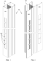
- Fig. 1 provides a perspective view of an exemplary dual-sided, multi-piece hydroponic tower 100 in which each front face plate 101 is hingeably coupled to the tower body 103.
- each front face plate 101 is in the closed position.
- Fig. 2 provides a perspective view of the same hydroponic tower 100 with both face plates 101 shown in the open position.
- the invention may also be utilized in a single-sided configuration as illustrated by tower 300 shown in Figs. 3 and 4 .
- Tower 300 is similar in design to that of tower 100 except that the tower body 301 only includes a single tower cavity.
- towers 100 and 300 each include a plurality of cut-outs 105 for use with a compatible plant container such as the plant container disclosed in co-assigned and co-pending U.S. Patent Application Serial No. 15/910,445, filed 2 March 2018 .
- a compatible plant container such as the plant container disclosed in co-assigned and co-pending U.S. Patent Application Serial No. 15/910,445, filed 2 March 2018 .
- the multi-piece tower design disclosed in the present application is not limited to use with this particular plant container, rather the multi-piece hydroponic tower designs disclosed herein may be used with any suitably sized hydroponic plant container.
- cut-outs 105 are only meant to illustrate, not limit, the present tower design and it should be understood that the present invention is equally applicable to other cut-out designs.
- the plant containers may be ultrasonically welded, bonded, or otherwise attached to tower face 101.
- the tower In a traditional hydroponic tower, the tower is extruded as a single piece. Due to the inclusion of the tower cavity, the extrusion process must operate at a relatively low rate in order to allow sufficient time for the heat contained within the tower cavity to be released.
- the body portion e.g., dual-sided body portion 103 and single-sided body portion 301
- the heat generated during the extrusion process is no longer trapped within the tower body, thereby allowing the extrusion process to operate much more quickly, thereby lowering manufacturing costs.
- the same body portion can be used with a variety of different face plates, face plates that may be configured for different plant containers, different cut-out designs, and/or different spacing between plants. This flexibility yields decreased manufacturing cost while providing additional value to the end customer (i.e., the grower).
- separating the tower into a body portion and a face portion allows features such as the plant container cut-outs 105 to be punched out during the extrusion process. This is in marked contrast, both in terms of time and cost, to the prior approach of utilizing a computer numerical control (CNC) machine to fabricate the cut-outs/features after the tower extrusion has been completed.
- CNC computer numerical control
- the physical requirements placed on the hydroponic tower depend on the exact nature of its intended use. Some of the use characteristics that impact design requirements include (i) desired tower height, (ii) number of plants per unit length, (iii) expected plant size at maturity and prior to harvesting, (iv) expected weight per plant and corresponding container, (v) intended means used to transfer plants/containers into and out of the tower, (vi) water/nutrient delivery system, etc.
- the towers disclosed herein are designed to hold a minimum distributed load of 11, 3kg (25 pounds) over 508cm (200 inches) for a single-sided tower, and a minimum distributed load of 22,7kg (50 pounds) over 508cm (200 inches) for a dual-sided tower.
- the hinge and fastener assemblies described below are designed to withstand a 11,3kg (25 pounds) shear load over a 508cm (200 inches) length parallel to the front face, and a 20,4kg (45 pounds) point force perpendicular to the front face.
- the cross-section of the tower cavities disclosed herein are selected to be in the range of 3,81cm (1,5 inches) by 3,81cm (1,5 inches) to 7,62cm (3 inches) to 7,62cm (3 inches), where the term “tower cavity” refers to the region within the body of the tower and behind the tower face plate.
- wall thickness is within the range of 0,17cm (0,65 inch) to 0,19cm (0,075 inch) .
- a dual-sided hydroponic tower such as that shown in Figs. 1 and 2 , has two back-to-back cavities, each preferably within the noted size range. It should be understood, however, that the invention is not limited to tower cavities with a particular cross-section or size, and the descriptions provided herein are based on preferred embodiments of the invention and are not meant to limit the scope of the invention.
- the strength of the tower depends on the specific tower design which, in large part, depends on the intended crop, the means used to plant and harvest, the intended water/nutrient delivery system, the desired tower-to-tower packing density, etc.
- the dual-sided tower has the added benefit of dramatically increasing tower stiffness.
- fins can be added to the back surface of the tower as described and illustrated in co-pending U.S. Patent Application Serial No. 15/910,601, filed 2 March 2018
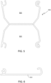
- Fig. 5 provides a cross-sectional view of tower body 103 while Fig. 6 provides a cross-sectional view of face plate 101.
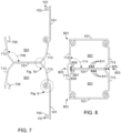
- Figs. 7 and 8 provide cross-sectional views of tower 100 with the face plates in the open and closed positions, respectively.
- both the body portion and the face plates are extruded, and features such as cut-outs 105 are punched during the process.
- both components are fabricated from plastic (e.g., polyethylene, polypropylene, polyvinyl chloride, polytetrafluoroethylene, acrylonitrile butadiene styrene (ABS), etc.), and more preferably from an opaque ABS plastic that is colored white.
- plastic e.g., polyethylene, polypropylene, polyvinyl chloride, polytetrafluoroethylene, acrylonitrile butadiene styrene (ABS), etc.
- ABS plastic e.g., polyethylene, polypropylene, polyvinyl chloride, poly
- a hinged front face plate has been found by the inventors to simplify tower maintenance in general, and tower cleaning in particular.
- the face plates are unhinged (i.e., opened) from the body to allow easy access to the body cavity 501. After cleaning, the face plates are closed. Since the face plates remain attached to the tower body throughout the cleaning process, it is easier to maintain part alignment and to insure that each face plate is properly associated with the appropriate tower body and, assuming a double-sided tower body, that each face plate is properly associated with the appropriate side of a specific tower body.
- both face plates can be opened and simultaneously planted and/or harvested, thus eliminating the step of planting and/or harvesting one side and then rotating the tower and planting and/or harvesting the other side.
- Fig. 9 provides a detailed cross-sectional view of the preferred embodiment of the hinge.
- the end portion 901 of face plate 903 is curved and sized to fit within, and rotate about, the curved end portion of body side wall 907.
- the end portion of the side wall is shaped to form two concentric surfaces 905A and 905B.
- Face plate end portion 901 rotates about and within the space formed by surfaces 905A and 905B.
- the end portions of both the tower body and the face plate must be elastically deformed during assembly. Once assembled, the face plate cannot be removed from the body without applying excessive force, thus minimizing the risk of accidental disassembly during planting, harvesting and/or tower maintenance.
- the limitation placed on the maximum opening of the hinged face plate is determined by the specific design of the hinged pieces, i.e., face plate end portion 901 and the curved end portion 905A/905B of the tower body.
- the end portion of the face plate includes a second bend at position 909, resulting in face plate surface 911 contacting tower body surface 913 when the face plate is in the fully open position.
- this contact point limits hinge movement such that the plane of face plate 101 is approximately perpendicular to rear cavity surface 701 when the face plate is in the fully open position, and more preferably limits hinge movement such that there is an angle of approximately 86 degrees between the plane of the face plate and that of the rear cavity surface 701 when the hinge is fully open.
- fasteners 801 are comprised of snap-fit fasteners.
- Each snap-fit fastener 801 is comprised of a first portion 703 formed on the face plate at a location distal from face plate end portion 901, and a second portion 705 formed on the edge of the tower body at a location opposite that of hinge end portions 905A/905B.
- snap-fit fasteners can utilize a variety of shapes, in the preferred embodiment snap-fit fastener portion 703 is generally cylindrically with body portion 705 having a complimentary shape. Slot 707 in snap-fit portion 703 allows portion 703 to compress more readily during fastening.
- the side walls of each tower cavity are tapered, thus ensuring that the tower face plates can open without the plant plug holders clipping the side walls.
- the flare out of each side wall is approximately 10 degrees, resulting in an angle 709 of approximately 100 degrees.
- angle 711 is approximately 90 degrees (i.e., 90 degrees plus/minus 5 degrees).
- the tower cavity 501 has an approximately square or rectangular shape as shown.
- the junction 1001 between the rear cavity wall 701 and each side wall has a strain relief feature with a 0,03cm (0,012 inch) radius.
- the dual-sided tower includes a large "V" shaped groove 803 that runs along the length of the tower, and on either side of the tower as shown.
- Groove 803 is centered on the side of tower, evenly splitting the two tower cavities. Note that in the single-sided configuration (e.g., Figs. 3 and 4 ), only half of the groove (e.g., groove 303) is required.
- groove 803 has a depth 805 of approximately 0,89cm ( ⁇ 0,25cm) (0,35 inch ( ⁇ 0,1 inch)).
- the angle 807 between side wall portions 809 is preferably within the range of 90 to 110 degrees, and more preferably 102 degrees.
- Groove 803, or groove 303 in the single-sided configuration provides an alignment feature that can be used when coupling planters, harvesters, or other equipment to the tower. This is an especially useful feature in an automated system.
- An additional benefit of groove 803, or groove 303 in the single-sided configuration is that it reduces the width of rear cavity surface 701. Since water and nutrients are preferably supplied to the plants within the hydroponic tower by directing the water/nutrient flow along surface 701, reducing the width of this surface increases the likelihood that the water and nutrients flowing down the surface reach the plants contained within the tower.
- the hydroponic towers of the present invention are not limited to a specific water/nutrient delivery system.
- a wicking system may be implemented within the disclosed towers.
- the water/nutrient mix is directed towards the cavity rear surface 701 where it can then flow downward, feeding the plants contained in the individual plant containers that are fit into each tower cut-out.
- a series of vertical ridges 811 are fabricated onto the rear cavity wall 701 of each cavity 501.
- each ridge 811 is 0,16cm (0,0625 inches) will and extends from the wall surface by 0,03cm (0,012 inch). It will be appreciated that other ridge dimensions can be used, and that the ridges do not have to be uniform across the entire surface, i.e., the ridges in the center could be wider and/or deeper than those to either side of the wall center.
Landscapes
- Life Sciences & Earth Sciences (AREA)
- Environmental Sciences (AREA)
- Engineering & Computer Science (AREA)
- Mechanical Engineering (AREA)
- General Engineering & Computer Science (AREA)
- Hydroponics (AREA)
- Water Supply & Treatment (AREA)
Description
- The present invention relates generally to hydroponic growing systems and, more particularly, to a hydroponic tower that provides increased planting consistency, decreased manufacturing time and cost, and improved tower characteristics (e.g., strength, ease of cleaning, efficiency of use, etc.).
- Given the continued growth of the world's population, and given that the regions allocated for agricultural pursuits have decreased or simply become less favorable to such activities, the ability of conventional farms to feed the world's growing population has become increasingly taxed. Additionally, since population centers and agricultural centers are frequently not co-located, and due to the time and expense associated with shipping agricultural goods, in many regions of the world only the wealthy are able to obtain adequate supplies of non-processed food, i.e., raw fruits and vegetables. Furthermore, the fruits and vegetables that do reach population centers are likely to be of decreased nutritional content and flavor, both due to the distance that they have traveled and the fact that much of today's produce is bred for durability and fertility rather than flavor & nutrition. As a result, there has been a renewed interest in soilless growing techniques that do not require the use of pesticides, drastically reduce the use of water, and allow for growing varietals that are bred for nutrition and flavor instead of durability.
- Hydroponics is a soilless growing technique in which plants are grown using a liquid solution of water and nutrients. The roots of the plants are typically maintained in a fibrous or granular material, often comprised of plastic, and fed via a wick, drip, nutrient film, or other nutrient delivery system. Hydroponic growing systems are often established within indoor facilities, thus allowing them to be located in or near population centers. This approach also provides exceptional climate control (i.e., temperature, humidity, air flow, CO2 concentration, light wavelength, intensity and duration, etc.) as well as improved pest and disease control, thus allowing an indoor hydroponic farm to succeed in a region in which the outside environment and/or the soil conditions are inhospitable to the use of conventional farming techniques. Furthermore, hydroponic and other soilless growing techniques can yield extremely high plant densities, especially in those instances in which either horizontal stacking systems or vertical growth towers are used.
- While hydroponic farming techniques offer a number of advantages over conventional farming techniques, in order to achieve large-scale adoption of these techniques it is vital that the cost per plant be competitive with the costs associated with conventional farming techniques. Accordingly, the present invention provides a hydroponic tower that achieves increased planting consistency, increased tower strength, decreased manufacturing time and cost, and simplified maintenance between use cycles.
WO2017109279 (A1 ) relates to a plant cultivation apparatus comprising a cultivation unit that has at least a vertical cultivation device for holding plants to be cultivated and a plant growth arrangement for treating the plants. An elongated framework of the cultivation device is a module structured composition consisting at least of a bottom element, a top element and/or an intermediate element and elongated wall elements with holes and/or sockets, the elements comprising fastening means for coupling of the elements removably with each other on a quick release principal.CN204616518U relates to a vertical type cultivation ware containing a hollow tube and a locating part. - According to a first aspect of the present invention there is provided the mutli-piece hydroponic tower of
claim 1. Also disclosed is a multi-piece hydroponic tower comprised of (i) a tower body that defines a first tower cavity, where the first tower cavity is configured to provide a passageway for a water/nutrient mix, and where a first edge portion of the tower body includes a first tower body hinge member; (ii) a first tower face plate, where an edge portion of the first tower face plate includes a first face plate hinge member, where the first tower face plate is hingeably coupled to the tower body via the first tower body hinge member and the first face plate hinge member, where the first tower face plate is positionable relative to the tower body in at least a first tower cavity closed position and a first tower cavity open position, and where the first tower face plate includes a first plurality of plant container cut-outs configured to accept a first plurality of plant containers; and (iii) a first fastener configured to temporarily latch the first tower face plate to the tower body when the first tower face plate is in the first tower cavity closed position. The first fastener may be comprised of a first plurality of fasteners. The first fastener may be comprised of a first snap-fit fastener. The tower body and the first tower face plate may be fabricated from plastic (e.g., polyethylene, polypropylene, polyvinyl chloride, polytetrafluoroethylene, and acrylonitrile butadiene styrene, etc.) and may be white. - The multi-piece hydroponic tower may be a dual-sided hydroponic tower, where the tower body defines a first tower cavity and a second tower cavity, where the first body hinge member of the first edge portion of the tower body corresponds to the first tower cavity, and where the tower body is further comprised of a second tower body hinge member corresponding to a second edge portion, the second tower body hinge member of the second edge portion of the tower body corresponding to the second tower cavity. The dual-sided hydroponic tower includes (i) a second tower face plate, where an edge portion of the second tower face plate includes a second face plate hinge member, where the second tower face plate is hingeably coupled to the tower body via the second tower body hinge member and the second face plate hinge member, where the second tower face plate is positionable relative to the tower body in at least a second tower cavity closed position and a second tower cavity open position, and where the second tower face plate includes a second plurality of plant container cut-outs configured to accept a second plurality of plant containers; and (ii) a second fastener configured to temporarily latch the second tower face plate to the tower body when the second tower face plate is in the second tower cavity closed position. The second fastener may be comprised of a second plurality of fasteners. The second fastener may be comprised of a second snap-fit fastener.
- In a configuration in which the multi-piece hydroponic tower is a dual-sided hydroponic tower: (i) the first tower cavity may be comprised of a first side wall, a second side wall and a first rear cavity wall, where the first side wall flares out relative to the first rear cavity wall when the first tower face plate is positioned in the first tower cavity open position, and where the second side wall flares out relative to the first rear cavity wall when the first tower face plate is positioned in the first tower cavity open position; and (ii) the second tower cavity may be comprised of a third side wall, a fourth side wall and a second rear cavity wall, where the third side wall flares out relative to the second rear cavity wall when the second tower face plate is positioned in the second tower cavity open position, and where the fourth side wall flares out relative to the second rear cavity wall when the second tower face plate is positioned in the second tower cavity open position. In this configuration the first side wall is at an angle of approximately 100 degrees relative to the first rear cavity wall when the first tower face plate is positioned in the first tower cavity open position; the second side wall is at an angle of approximately 100 degrees relative to the first rear cavity wall when the first tower face plate is positioned in the first tower cavity open position; the third side wall is at an angle of approximately 100 degrees relative to the second rear cavity wall when the second tower face plate is positioned in the second tower cavity open position; and the fourth side wall is at an angle of approximately 100 degrees relative to the second rear cavity wall when the second tower face plate is positioned in the second tower cavity open position. In this configuration the first side wall is approximately perpendicular to the first rear cavity wall when the first tower face plate is positioned in the first tower cavity closed position; the second side wall is approximately perpendicular to the first rear cavity wall when the first tower face plate is positioned in the first tower cavity closed position; the third side wall is approximately perpendicular to the second rear cavity wall when the second tower face plate is positioned in the second tower cavity closed position; and the fourth side wall is approximately perpendicular to the second rear cavity wall when the second tower face plate is positioned in the second tower cavity closed position. In this configuration a first strain relief feature may be positioned at a first junction, where the first junction is formed between the first side wall and the first rear cavity wall; a second strain relief feature may be positioned at a second junction, where the second junction is formed between the second side wall and the first rear cavity wall; a third strain relief feature may be positioned at a third junction, where the third junction is formed between the first side wall and the second side wall; a fourth strain relief feature may be positioned at a fourth junction, where the fourth junction is formed between the third side wall and the second rear cavity wall; a fifth strain relief feature may be positioned at a fifth junction, where the fifth junction is formed between the fourth side wall and the second rear cavity wall; and a sixth strain relief feature may be positioned at a sixth junction, where the sixth junction is formed between the third side wall and the fourth side wall.
- In a configuration in which the multi-piece hydroponic tower is a dual-sided hydroponic tower, the hydroponic tower may include (i) a first V-shaped groove running along the length of a first side of the tower body, where the first V-shaped groove is centered between the first tower cavity and the second tower cavity; and (ii) a second V-shaped groove running along the length of a second side of the tower body, where the second V-shaped groove is centered between the first tower cavity and the second tower cavity. In this configuration the first V-shaped groove may be formed from a first side wall portion corresponding to the first tower cavity and a second side wall portion corresponding to the second tower cavity, and the second V-shaped groove may be formed from a third side wall portion corresponding to the first tower cavity and a fourth side wall portion corresponding to the second tower cavity. In this configuration a first strain relief feature may be positioned at a first junction, where the first junction is formed between the first side wall portion and the first rear cavity wall; a second strain relief feature may be positioned at a second junction, where the second junction is formed between the second side wall portion and the first rear cavity wall; a third strain relief feature may be positioned at a third junction, where the third junction is formed between the first side wall portion and the second side wall portion; a fourth strain relief feature may be positioned at a fourth junction, where the fourth junction is formed between the third side wall portion and the second rear cavity wall; a fifth strain relief feature may be positioned at a fifth junction, where the fifth junction is formed between the fourth side wall portion and the second rear cavity wall; and a sixth strain relief feature may be positioned at a sixth junction, where the sixth junction is formed between the third side wall portion and the fourth side wall portion. In this configuration the first side wall portion is at an angle of between 90 and 110 degrees, and preferably at an angle of approximately 102 degrees, relative to the second side wall portion when the first tower face plate is in the first tower cavity closed position and the second tower face plate is in the second tower cavity closed position; and the third side wall portion is at an angle of between 90 and 110 degrees, and preferably at an angle of approximately 102 degrees, relative to the fourth side wall portion when the first tower face plate is in the first tower cavity closed position and the second tower face plate is in the second tower cavity closed position.
- In a configuration in which the multi-piece hydroponic tower is a dual-sided hydroponic tower, the first rear cavity wall and the second rear cavity wall may each include a plurality of vertical ridges. The vertical ridges may be of uniform width.
- A further understanding of the nature and advantages of the present invention may be realized by reference to the remaining portions of the specification and the drawings.
- It should be understood that the accompanying figures are only meant to illustrate, not limit, the scope of the invention and should not be considered to be to scale. Additionally, the same reference label on different figures should be understood to refer to the same component or a component of similar functionality.
-
Fig. 1 provides a perspective view of an exemplary dual-sided, multi-piece hydroponic tower with hingeably coupled front face plates, this view showing the face plates in the closed position; -
Fig. 2 provides a perspective view of the dual-sided, multi-piece hydroponic tower shown inFig. 1 , this view showing the face plates in the open position; -
Fig. 3 provides a perspective view of an exemplary single-sided, multi-piece hydroponic tower with a hingeably coupled front face plate, this view showing the face plate in the closed position; -
Fig. 4 provides a perspective view of the single-sided, multi-piece hydroponic tower shown inFig. 3 , this view showing the face plate in the open position; -
Fig. 5 provides a cross-sectional view of the dual cavity tower body utilized in the tower shown inFigs. 1 and 2 ; -
Fig. 6 provides a cross-sectional view of the face plate member utilized in the towers shown inFigs. 1-4 ; -
Fig. 7 provides a cross-sectional view of the multi-piece tower assembly shown inFigs. 1 and 2 , this view showing both face plates in the open position; -
Fig. 8 provides a cross-sectional view of the multi-piece tower assembly shown inFigs. 1 and 2 , this view showing both face plates in the closed position; -
Fig. 9 provides a detailed cross-sectional view of the hinge region of the multi-piece hydroponic tower of the invention; and -
Fig. 10 provides a detailed cross-sectional view of a portion of the dual-sided, multi-piece tower body corresponding to the hydroponic tower illustrated inFigs. 1 and 2 , this view showing the intersection of the cavity rear wall with the cavity side walls. - As used herein, the singular forms "a", "an" and "the" are intended to include the plural forms as well, unless the context clearly indicates otherwise. The terms "comprises", "comprising", "includes", and/or "including", as used herein, specify the presence of stated features, process steps, operations, elements, and/or components, but do not preclude the presence or addition of one or more other features, process steps, operations, elements, components, and/or groups thereof. As used herein, the term "and/or" and the symbol "/" are meant to include any and all combinations of one or more of the associated listed items. Additionally, while the terms first, second, etc. may be used herein to describe various steps, calculations, or components, these steps, calculations, or components should not be limited by these terms, rather these terms are only used to distinguish one step, calculation, or component from another. For example, a first calculation could be termed a second calculation, and, similarly, a first step could be termed a second step, and, similarly, a first component could be termed a second component, without departing from the scope of this disclosure.
-
Fig. 1 provides a perspective view of an exemplary dual-sided, multi-piecehydroponic tower 100 in which eachfront face plate 101 is hingeably coupled to thetower body 103. InFig. 1 eachfront face plate 101 is in the closed position.Fig. 2 provides a perspective view of the samehydroponic tower 100 with bothface plates 101 shown in the open position. Although the dual-sided configuration is preferred, the invention may also be utilized in a single-sided configuration as illustrated bytower 300 shown inFigs. 3 and 4 . Tower 300 is similar in design to that oftower 100 except that thetower body 301 only includes a single tower cavity. - In order to illustrate the tower design,
towers outs 105 for use with a compatible plant container such as the plant container disclosed in co-assigned and co-pendingU.S. Patent Application Serial No. 15/910,445, filed 2 March 2018 outs 105 are only meant to illustrate, not limit, the present tower design and it should be understood that the present invention is equally applicable to other cut-out designs. It will be understood that the plant containers may be ultrasonically welded, bonded, or otherwise attached to towerface 101. - In a traditional hydroponic tower, the tower is extruded as a single piece. Due to the inclusion of the tower cavity, the extrusion process must operate at a relatively low rate in order to allow sufficient time for the heat contained within the tower cavity to be released. By separately manufacturing the body portion (e.g., dual-
sided body portion 103 and single-sided body portion 301) of the hydroponic tower from the face plates, the heat generated during the extrusion process is no longer trapped within the tower body, thereby allowing the extrusion process to operate much more quickly, thereby lowering manufacturing costs. Additionally, by separating the tower body from the face plate, or face plates, the same body portion can be used with a variety of different face plates, face plates that may be configured for different plant containers, different cut-out designs, and/or different spacing between plants. This flexibility yields decreased manufacturing cost while providing additional value to the end customer (i.e., the grower). Lastly, separating the tower into a body portion and a face portion allows features such as the plant container cut-outs 105 to be punched out during the extrusion process. This is in marked contrast, both in terms of time and cost, to the prior approach of utilizing a computer numerical control (CNC) machine to fabricate the cut-outs/features after the tower extrusion has been completed. - It will be appreciated that the physical requirements placed on the hydroponic tower depend on the exact nature of its intended use. Some of the use characteristics that impact design requirements include (i) desired tower height, (ii) number of plants per unit length, (iii) expected plant size at maturity and prior to harvesting, (iv) expected weight per plant and corresponding container, (v) intended means used to transfer plants/containers into and out of the tower, (vi) water/nutrient delivery system, etc. The towers disclosed herein are designed to hold a minimum distributed load of 11, 3kg (25 pounds) over 508cm (200 inches) for a single-sided tower, and a minimum distributed load of 22,7kg (50 pounds) over 508cm (200 inches) for a dual-sided tower. The hinge and fastener assemblies described below are designed to withstand a 11,3kg (25 pounds) shear load over a 508cm (200 inches) length parallel to the front face, and a 20,4kg (45 pounds) point force perpendicular to the front face.
- In general, the cross-section of the tower cavities disclosed herein are selected to be in the range of 3,81cm (1,5 inches) by 3,81cm (1,5 inches) to 7,62cm (3 inches) to 7,62cm (3 inches), where the term "tower cavity" refers to the region within the body of the tower and behind the tower face plate. Preferably wall thickness is within the range of 0,17cm (0,65 inch) to 0,19cm (0,075 inch) . A dual-sided hydroponic tower, such as that shown in
Figs. 1 and 2 , has two back-to-back cavities, each preferably within the noted size range. It should be understood, however, that the invention is not limited to tower cavities with a particular cross-section or size, and the descriptions provided herein are based on preferred embodiments of the invention and are not meant to limit the scope of the invention. - The strength of the tower depends on the specific tower design which, in large part, depends on the intended crop, the means used to plant and harvest, the intended water/nutrient delivery system, the desired tower-to-tower packing density, etc. As a general guideline, however, the inventors have found that in addition to providing increased packing density and a lower overall tower cost (based on cost per plant), the dual-sided tower has the added benefit of dramatically increasing tower stiffness. To achieve the same stiffness in a single-sided tower without altering wall thickness or cavity size, fins can be added to the back surface of the tower as described and illustrated in co-pending
U.S. Patent Application Serial No. 15/910,601, filed 2 March 2018 -
Fig. 5 provides a cross-sectional view oftower body 103 whileFig. 6 provides a cross-sectional view offace plate 101.Figs. 7 and 8 provide cross-sectional views oftower 100 with the face plates in the open and closed positions, respectively. Preferably both the body portion and the face plates are extruded, and features such as cut-outs 105 are punched during the process. Although any of a variety of materials can be used in the manufacture of the tower, preferably both components are fabricated from plastic (e.g., polyethylene, polypropylene, polyvinyl chloride, polytetrafluoroethylene, acrylonitrile butadiene styrene (ABS), etc.), and more preferably from an opaque ABS plastic that is colored white. Using an opaque PVC material that prevents light from entering the tower helps to minimize algae blooms while the white coloring increases the amount of light reflected back onto the plants. - The use of a hinged front face plate has been found by the inventors to simplify tower maintenance in general, and tower cleaning in particular. For example, to clean the tower the face plates are unhinged (i.e., opened) from the body to allow easy access to the
body cavity 501. After cleaning, the face plates are closed. Since the face plates remain attached to the tower body throughout the cleaning process, it is easier to maintain part alignment and to insure that each face plate is properly associated with the appropriate tower body and, assuming a double-sided tower body, that each face plate is properly associated with the appropriate side of a specific tower body. Additionally, if the planting and/or harvesting operations are performed with the face plate in the open position, for the dual-sided configuration both face plates can be opened and simultaneously planted and/or harvested, thus eliminating the step of planting and/or harvesting one side and then rotating the tower and planting and/or harvesting the other side. -
Fig. 9 provides a detailed cross-sectional view of the preferred embodiment of the hinge. In this embodiment, theend portion 901 offace plate 903 is curved and sized to fit within, and rotate about, the curved end portion ofbody side wall 907. As shown, the end portion of the side wall is shaped to form twoconcentric surfaces plate end portion 901 rotates about and within the space formed bysurfaces - It will be appreciated that the limitation placed on the maximum opening of the hinged face plate is determined by the specific design of the hinged pieces, i.e., face
plate end portion 901 and thecurved end portion 905A/905B of the tower body. In the illustrated embodiment, the end portion of the face plate includes a second bend atposition 909, resulting inface plate surface 911 contactingtower body surface 913 when the face plate is in the fully open position. In the preferred embodiment, this contact point limits hinge movement such that the plane offace plate 101 is approximately perpendicular torear cavity surface 701 when the face plate is in the fully open position, and more preferably limits hinge movement such that there is an angle of approximately 86 degrees between the plane of the face plate and that of therear cavity surface 701 when the hinge is fully open. - Any of a variety of different fastener types can be used to latch
face plate 101 to the tower body when the hinge is closed. In the preferred embodiment and as illustrated,fasteners 801 are comprised of snap-fit fasteners. Each snap-fit fastener 801 is comprised of afirst portion 703 formed on the face plate at a location distal from faceplate end portion 901, and asecond portion 705 formed on the edge of the tower body at a location opposite that ofhinge end portions 905A/905B. While snap-fit fasteners can utilize a variety of shapes, in the preferred embodiment snap-fit fastener portion 703 is generally cylindrically withbody portion 705 having a complimentary shape.Slot 707 in snap-fit portion 703 allowsportion 703 to compress more readily during fastening. - In at least one preferred embodiment, the side walls of each tower cavity are tapered, thus ensuring that the tower face plates can open without the plant plug holders clipping the side walls. Preferably the flare out of each side wall is approximately 10 degrees, resulting in an
angle 709 of approximately 100 degrees. Note that when the face plate is closed, the side walls are pulled inward such that the angle between the side walls and the rear cavity surface, i.e.,angle 711, is approximately 90 degrees (i.e., 90 degrees plus/minus 5 degrees). As a result, when the face plate is closed, thetower cavity 501 has an approximately square or rectangular shape as shown. - Due to the difference in cross-section between the open (i.e.,
Fig. 7 ) and closed (i.e.,Fig. 8 ) configurations, preferably steps are taken to ensure that cavity side walls do not bow out when the face plates are closed. Preferably and as shown inFig. 10 , thejunction 1001 between therear cavity wall 701 and each side wall has a strain relief feature with a 0,03cm (0,012 inch) radius. - As shown in the figures, preferably the dual-sided tower includes a large "V" shaped
groove 803 that runs along the length of the tower, and on either side of the tower as shown.Groove 803 is centered on the side of tower, evenly splitting the two tower cavities. Note that in the single-sided configuration (e.g.,Figs. 3 and 4 ), only half of the groove (e.g., groove 303) is required. In at least one embodiment of the invention utilizing a double-sided configuration (e.g.,Figs. 1 and 2 ),groove 803 has adepth 805 of approximately 0,89cm (±0,25cm) (0,35 inch (±0,1 inch)). In this embodiment theangle 807 betweenside wall portions 809 is preferably within the range of 90 to 110 degrees, and more preferably 102 degrees. -
Groove 803, or groove 303 in the single-sided configuration, provides an alignment feature that can be used when coupling planters, harvesters, or other equipment to the tower. This is an especially useful feature in an automated system. An additional benefit ofgroove 803, or groove 303 in the single-sided configuration, is that it reduces the width ofrear cavity surface 701. Since water and nutrients are preferably supplied to the plants within the hydroponic tower by directing the water/nutrient flow alongsurface 701, reducing the width of this surface increases the likelihood that the water and nutrients flowing down the surface reach the plants contained within the tower. - The hydroponic towers of the present invention are not limited to a specific water/nutrient delivery system. Thus, for example, a wicking system may be implemented within the disclosed towers. As noted above, however, in the preferred embodiment the water/nutrient mix is directed towards the cavity
rear surface 701 where it can then flow downward, feeding the plants contained in the individual plant containers that are fit into each tower cut-out. In order to help control water/nutrient flow along the back wall of the tower cavity, preferably a series ofvertical ridges 811 are fabricated onto therear cavity wall 701 of eachcavity 501. In this embodiment, eachridge 811 is 0,16cm (0,0625 inches) will and extends from the wall surface by 0,03cm (0,012 inch). It will be appreciated that other ridge dimensions can be used, and that the ridges do not have to be uniform across the entire surface, i.e., the ridges in the center could be wider and/or deeper than those to either side of the wall center. - Systems and methods have been described in general terms as an aid to understanding details of the invention. In some instances, well-known structures, materials, and/or operations have not been specifically shown or described in detail to avoid obscuring aspects of the invention. In other instances, specific details have been given in order to provide a thorough understanding of the invention. Therefore the disclosures and descriptions herein are intended to be illustrative, but not limiting, of the scope of the invention, which is defined by the appended claims.
Claims (13)
- A multi-piece hydroponic tower (100), comprising:a tower body (103), said tower body comprising a rear cavity wall, and first and second side walls extending from opposing edges of the rear cavity wall, thereby defining a first tower cavity (501), said first tower cavity configured to provide a passageway (811) for a water/nutrient mix;a first tower face plate (101), wherein an edge portion of said first tower face plate is hingeably coupled to said first side wall of said tower body (103), wherein said first tower face plate (101) is configured to be positioned relative to said tower body in at least a first tower cavity closed position and a first tower cavity open position via said hingeably coupled edge portion, said first tower face plate comprising a first plurality of plant container cut-outs (105), said first plurality of plant container cut-outs configured to accept a first plurality of plant containers; anda first fastener (801) configured to temporarily latch said first tower face plate (101) to said second side wall of said tower body (103) when said first tower face plate is in said first tower cavity closed position.
- The multi-piece hydroponic tower of claim 1, wherein said multi piece hydroponic tower is a dual-sided hydroponic tower, wherein said tower body comprises third and fourth side walls extending from the opposing edges of the rear cavity wall to define a second tower cavity (501), said multi-piece hydroponic tower further comprising:a second tower face plate (101), wherein an edge portion of said second tower face plate is hingeably coupled to said third side wall of said tower body (103), wherein said second tower face plate (101) is configured to be positioned relative to said tower body in at least a second tower cavity closed position and a second tower cavity open position via said hingeably coupled edge portion, said second tower face plate comprising a second plurality of plant container cut-outs (105), said second plurality of plant container cut outs configured to accept a second plurality of plant containers; anda second fastener (801) configured to temporarily latch said second tower face plate (101) to said fourth side wall of said tower body (103) when said second tower face plate is in said second tower cavity closed position.
- The multi-piece hydroponic tower of claim 1 or claim 2, said first fastener (801) comprising a first snap-fit fastener.
- The multi-piece hydroponic tower of claim 2 or claim 3, said second fastener (801) comprising a second snap-fit fastener.
- The multi-piece hydroponic tower of claim 2, further comprising:a first plurality of vertical ridges (811) formed on the first rear cavity wall (701); anda second plurality of vertical ridges (811) formed on the second rear cavity wall (701).
- The multi-piece hydroponic tower of claim 5, said first plurality of vertical ridges (811) of uniform width, and said second plurality of vertical ridges (811) of uniform width.
- The multi-piece hydroponic tower of claim 2, further comprising:a first V-shaped groove (803) running along the length of a first side of said tower body, said first V-shaped groove centered between said first tower cavity (501) and said second tower cavity (501); anda second V-shaped groove (803) running along the length of a second side of said tower body, said second V-shaped groove centered between said first tower cavity and said second tower cavity.
- The multi-piece hydroponic tower of claim 7, said first V-shaped groove (803) formed from a first side wall portion (809) corresponding to said first tower cavity (501) and a second side wall portion (809) corresponding to said second tower cavity (501); and
said second V-shaped groove formed from a third side wall portion corresponding to said first tower cavity and a fourth side wall portion corresponding to said second tower cavity. - The multi-piece hydroponic tower of claim 2, wherein:said first side wall flares out relative to said first rear cavity wall when said first tower face plate (101) is positioned in said first tower cavity open position, and wherein said second side wall flares out relative to said first rear cavity wall when said first tower face plate is positioned in said first tower cavity open position; andsaid third side wall flares out relative to said second rear cavity wall when said second tower face plate (101) is positioned in said second tower cavity open position, and wherein said fourth side wall flares out relative to said second rear cavity wall when said second tower face plate is positioned in said second tower cavity open position.
- The multi-piece hydroponic tower of claim 9, wherein said first side wall (713) is at an angle of approximately 100 degrees relative to said first rear cavity wall (701) when said first tower face plate (101) is positioned in said first tower cavity open position, wherein said second side wall (713) is at an angle of approximately 100 degrees relative to said first rear cavity wall (701) when said first tower face plate is positioned in said first tower cavity open position, wherein said third side wall (713) is at an angle of approximately 100 degrees relative to said second rear cavity wall (701) when said second tower face plate (101) is positioned in said second tower cavity open position, and wherein said fourth side wall (713) is at an angle of approximately 100 degrees relative to said second rear cavity wall (701) when said second tower face plate is positioned in said second tower cavity open position.
- The multi-piece hydroponic tower of claim 9, wherein said first side wall (713) is approximately perpendicular to said first rear cavity wall (701) when said first tower face plate (101) is positioned in said first tower cavity closed position, wherein said second side wall (713) is approximately perpendicular to said first rear cavity wall (701) when said first tower face plate is positioned in said first tower cavity closed position, wherein said third side wall (713) is approximately perpendicular to said second rear cavity wall (701) when said second tower face plate (101) is positioned in said second tower cavity closed position, and wherein said fourth side wall (713) is approximately perpendicular to said second rear cavity wall when said second tower face plate is positioned in said second tower cavity closed position.
- The multi-piece hydroponic tower of claim 1 whereina first edge portion of said tower body includes a first tower body hinge member andan edge portion of said first tower face plate includes a first face plate hinge member, wherein said first tower face plate is hingeably coupled to said tower body via said first tower body hinge member.
- The multi-piece hydroponic tower of claim 2 wherein:said first body hinge member of said first edge portion of said tower body corresponds to said first tower cavity, said tower body further comprising a second tower body hinge member corresponding to a second edge portion of said tower body, said second tower body hinge member of said second edge portion of said tower body corresponding to said second tower cavity, andsaid second tower face plate is hingeably coupled to said tower body via said second tower body hinge member and said second face plate hinge member.
Applications Claiming Priority (3)
| Application Number | Priority Date | Filing Date | Title |
|---|---|---|---|
| US15/910,601 US10694689B2 (en) | 2018-03-02 | 2018-03-02 | Multi-piece hydroponic tower |
| US15/968,425 US10701875B2 (en) | 2018-03-02 | 2018-05-01 | Multi-piece hydroponic tower with hinged tower face |
| PCT/US2019/017719 WO2019168668A1 (en) | 2018-03-02 | 2019-02-12 | Multi-piece hydroponic tower with hinged tower face |
Publications (4)
| Publication Number | Publication Date |
|---|---|
| EP3758470A1 EP3758470A1 (en) | 2021-01-06 |
| EP3758470A4 EP3758470A4 (en) | 2021-04-07 |
| EP3758470B1 true EP3758470B1 (en) | 2024-06-19 |
| EP3758470C0 EP3758470C0 (en) | 2024-06-19 |
Family
ID=67767303
Family Applications (1)
| Application Number | Title | Priority Date | Filing Date |
|---|---|---|---|
| EP19760378.0A Active EP3758470B1 (en) | 2018-03-02 | 2019-02-12 | Multi-piece hydroponic tower with hinged tower face |
Country Status (8)
| Country | Link |
|---|---|
| US (2) | US10701875B2 (en) |
| EP (1) | EP3758470B1 (en) |
| JP (1) | JP7273857B2 (en) |
| KR (1) | KR102674093B1 (en) |
| CN (2) | CN112118730B (en) |
| AU (1) | AU2019227444B2 (en) |
| SG (1) | SG11202007970YA (en) |
| WO (1) | WO2019168668A1 (en) |
Families Citing this family (20)
| Publication number | Priority date | Publication date | Assignee | Title |
|---|---|---|---|---|
| US10694689B2 (en) * | 2018-03-02 | 2020-06-30 | Mjnn, Llc | Multi-piece hydroponic tower |
| US10729081B2 (en) * | 2018-03-02 | 2020-08-04 | Mjnn, Llc | Hydroponic tower with hinged tower face |
| US10986791B2 (en) * | 2018-03-02 | 2021-04-27 | Mjnn Llc | Hydroponic tower compatible plant plug holder |
| US10701875B2 (en) * | 2018-03-02 | 2020-07-07 | Mjnn, Llc | Multi-piece hydroponic tower with hinged tower face |
| CN112105256B (en) | 2018-03-21 | 2023-04-14 | Mjnn有限责任公司 | Vertical Grow Tower Conveyor System for Controlled Environment Agriculture |
| US11951610B2 (en) | 2018-07-31 | 2024-04-09 | Mjnn Llc | Opening apparatus for use with a multi-piece, hinged, hydroponic tower |
| USD895479S1 (en) * | 2018-08-09 | 2020-09-08 | Hyperponic, LLC | Vertical horticultural grow system |
| WO2020051271A1 (en) | 2018-09-07 | 2020-03-12 | Urban Geoponic Llc | Hydroponic tower assemblies and methods |
| US11723328B2 (en) | 2019-05-08 | 2023-08-15 | Mjnn Llc | Cleaning apparatus for use with a plant support tower |
| USD964787S1 (en) * | 2019-06-04 | 2022-09-27 | Urban Geoponic Llc | Hydroponic tower |
| US12016278B2 (en) * | 2019-06-06 | 2024-06-25 | Mjnn Llc | Irrigation system for vertical grow tower crop production facility |
| WO2021055001A1 (en) * | 2019-09-20 | 2021-03-25 | Mjnn Llc | Grow tower drive mechanism for agriculture production systems |
| WO2021202827A1 (en) | 2020-04-01 | 2021-10-07 | Shamrock Greens, Inc. | Multi-plane configurable grow system for controlled environment agriculture |
| US11609109B2 (en) | 2020-08-05 | 2023-03-21 | Mjnn Llc | Flow sensor for sensor network in controlled environment agriculture |
| WO2022061467A1 (en) | 2020-09-24 | 2022-03-31 | Cyclofields Indoor Farming Technology Inc. | Closed loop vertical disengageable aeroponic growing system |
| US20240324520A1 (en) * | 2021-07-21 | 2024-10-03 | Mjnn Llc | Vertical indexing of grow tower segments |
| USD1014206S1 (en) * | 2022-03-29 | 2024-02-13 | Grey & Co Pte. Ltd | Plant support structure |
| US20240260514A1 (en) * | 2023-02-02 | 2024-08-08 | Fernando Ortiz Monasterio Garza | Mounting panel for a vertical garden, vertical garden system with foldable panels, and mounting and dismounting methods thereof |
| USD1020413S1 (en) * | 2023-11-14 | 2024-04-02 | Huiya Huang | Moss pole |
| USD1034115S1 (en) * | 2024-01-29 | 2024-07-09 | Fanyu Guo | Plants-and-flowers planter and growth support |
Family Cites Families (84)
| Publication number | Priority date | Publication date | Assignee | Title |
|---|---|---|---|---|
| US1709860A (en) * | 1928-01-27 | 1929-04-23 | Jr John Thompson Lovett | Plant-ball package |
| US3896587A (en) * | 1973-06-25 | 1975-07-29 | Charles J Insalaco | Nursery pot having improved drainage |
| US4033072A (en) * | 1974-12-28 | 1977-07-05 | Hitoshi Kobayashi | Hydroponic cultivation apparatus |
| US4216622A (en) | 1978-09-19 | 1980-08-12 | Hackney Howard U Jr | Plant container |
| US4454684A (en) * | 1983-03-16 | 1984-06-19 | Hare Louis R O | Root augmentor for vertical horticulture |
| US5031359A (en) | 1983-11-09 | 1991-07-16 | Moffett Jr F Wesley | Garden structure and method of producing same |
| JPS6216262U (en) * | 1985-07-16 | 1987-01-30 | ||
| US4683674A (en) * | 1985-11-15 | 1987-08-04 | Barclay Horticulture Mfg. Ltd. | Compost bin |
| US5363594A (en) * | 1991-11-07 | 1994-11-15 | A.C.T. Inc. | Vertical gardens |
| US5251399A (en) * | 1992-10-23 | 1993-10-12 | Rasmussen Von O | Vertical plant stand |
| US5555676A (en) * | 1994-11-03 | 1996-09-17 | A.C.T., Inc. | Vertical planter apparatus and method |
| US5724768A (en) * | 1996-04-29 | 1998-03-10 | Ammann, Jr.; Paul R. | Aeroponic plant growth apparatus and method |
| US6357172B1 (en) | 1997-06-10 | 2002-03-19 | Teel Plastics, Inc. | Plant protector |
| US5913477A (en) * | 1998-07-07 | 1999-06-22 | Anthony A. Dean | Modular plant support and irrigation system |
| US6000173A (en) * | 1998-08-05 | 1999-12-14 | Schow; Matthew Alan | Hydroponic growing station with intermittent nutrient supply |
| US6612069B2 (en) | 1999-07-02 | 2003-09-02 | Randal D. A. Locke | Retrofitting aerating root pruner |
| CA2335311A1 (en) * | 2001-02-09 | 2002-08-09 | Claude Lapointe | Molded container for hydroponic culture and hydroponic system using same |
| US6477805B2 (en) * | 2001-03-08 | 2002-11-12 | Larry Austin Ware | Plant growth unit |
| US7373753B1 (en) * | 2001-10-04 | 2008-05-20 | Caruso Steven J | Gardening components |
| US6615542B2 (en) * | 2001-11-14 | 2003-09-09 | Larry Austen Ware | Plant growth unit |
| US7143544B2 (en) * | 2003-08-22 | 2006-12-05 | Rejean Roy | Hydroponic growing unit |
| US20080078118A1 (en) * | 2003-11-17 | 2008-04-03 | Aerogrow International, Inc. | Master gardener baskets and methods for growing plants |
| DE20320837U1 (en) | 2003-11-21 | 2005-03-24 | Sailer Reinhard | Plant holder has cylindrical wall with openings along it for plants arranged in groups |
| US7171782B2 (en) * | 2004-02-02 | 2007-02-06 | Felknor Ventures, Llc | Planter for growing plants |
| NL1027534C2 (en) * | 2004-11-17 | 2005-10-18 | W D Products Metaal B V | Cultivation gutter for supporting substrate material with a growing crop therein in a department store. |
| US7877927B2 (en) * | 2004-12-16 | 2011-02-01 | Mario Roy | Modular aeroponic/hydroponic container mountable to a surface |
| JP2009528827A (en) * | 2006-03-06 | 2009-08-13 | エレベイテッド ランドスケープ テクノロジーズ インク. | Vertical planting system |
| US20100236144A1 (en) * | 2007-06-14 | 2010-09-23 | Trentcom Aps Pty. Ltd. | Container for Growing Plants and Carrier Therefor |
| TWM367678U (en) * | 2008-12-16 | 2009-11-01 | Ke-Dan Ma | Structure of flower wall |
| US7980026B2 (en) | 2009-10-09 | 2011-07-19 | Paul H. Rosenberg | Calyx support for stemmed flowers |
| GB2475101B (en) * | 2009-11-09 | 2014-01-08 | Mark Laurence | Wall for growing plants |
| JP5319498B2 (en) * | 2009-11-10 | 2013-10-16 | サントリーホールディングス株式会社 | Planting container |
| US8250804B2 (en) * | 2009-11-16 | 2012-08-28 | Cheng Chung Chang | Plant pot holding device |
| US8418403B1 (en) * | 2010-04-09 | 2013-04-16 | Thomas L. Nuttman | Hanging stacked plant holders and watering systems |
| US10617075B2 (en) * | 2010-04-22 | 2020-04-14 | University Of Wyoming | Hydroponic produce display apparatus |
| US8365466B1 (en) * | 2010-04-22 | 2013-02-05 | Nathaniel Storey | Hydroponic produce display apparatus |
| US20120117871A1 (en) | 2010-11-15 | 2012-05-17 | Kelly William Luckett | Interlocking planter and planter system |
| TWI478663B (en) * | 2011-12-14 | 2015-04-01 | Ind Tech Res Inst | Planting container and planting tower |
| US8919041B2 (en) * | 2012-02-09 | 2014-12-30 | Vegherb, Llc | Lighting system for use in raised bed gardening or landscaping |
| US20140053463A1 (en) * | 2012-08-22 | 2014-02-27 | Abdessamad Khaled | Systems, methods, and devices for insulated grain germination |
| NL2009794C2 (en) * | 2012-11-13 | 2014-05-14 | Hevorma B V | GROWTH DEVICE FOR CROPS, USE OF SUCH DEVICE, AND A SERIES OF GROWTH DEVICES. |
| MX357232B (en) * | 2012-11-30 | 2018-06-13 | Eleven Solutions Rfe S A De C V | Ecological construction system for buildings with green walls. |
| KR101410898B1 (en) * | 2013-02-22 | 2014-06-24 | 박상숙 | Apparatus for cultivating at high position |
| US9101099B2 (en) * | 2013-03-28 | 2015-08-11 | Bryce D. Nagels | Hydroponic growing system |
| US8966819B1 (en) * | 2013-04-16 | 2015-03-03 | Neila Cosmann | Suspendable and stackable vertical planter |
| CN203563480U (en) * | 2013-11-22 | 2014-04-30 | 张晓辉 | Aquatic-plant cultivation and landscaping product |
| JP6375627B2 (en) * | 2014-01-24 | 2018-08-22 | 富士通株式会社 | Plant cultivation equipment |
| US9357715B2 (en) * | 2014-05-01 | 2016-06-07 | Brian Cottrell | Vertical planter |
| TWM494487U (en) | 2014-07-18 | 2015-02-01 | Huang Maggie | Vertical cultivator and vertical cultivation device |
| US9374953B2 (en) * | 2014-07-30 | 2016-06-28 | Indoor Farms Of America, Llc | Vertical aeroponic plant growing enclosure with support structure |
| US11464180B2 (en) * | 2014-07-30 | 2022-10-11 | Innovation Agri-Tech Group Ltd. | Vertical aeroponic plant growing enclosure |
| WO2016019330A1 (en) * | 2014-07-31 | 2016-02-04 | Living Greens Farm, Inc. | Growing system |
| US20160066525A1 (en) * | 2014-09-05 | 2016-03-10 | Group Rate Deals, LLC d/b/a Earth Prime Inc. | Hydroponic garden system |
| US20160120141A1 (en) * | 2014-10-29 | 2016-05-05 | Aero Development Corp | Aeroponic Growing Column and System |
| EP3220735B1 (en) | 2014-11-19 | 2020-07-22 | University of Wyoming | Vertical hydroponic tower array fixture system |
| US20180007849A1 (en) * | 2015-01-11 | 2018-01-11 | Living Box Ltd. | Hydroculture system |
| JP2018512888A (en) * | 2015-03-19 | 2018-05-24 | ロケハ リミテッド | System for indoor cultivation of plants under simulated natural lighting conditions |
| JP6842623B2 (en) * | 2015-04-10 | 2021-03-17 | エデン グリーン グローバル テクノロジーズ リミテッド | Hydroponics |
| CN105145325B (en) * | 2015-07-10 | 2017-06-16 | 哈尔滨工业大学 | A kind of special mobile plant wall system of external wall |
| US10736284B2 (en) * | 2015-09-01 | 2020-08-11 | Keith Baker | Vertical hydroponic system |
| MA40728A (en) * | 2015-10-20 | 2017-06-13 | Tower Garden Llc | IMPROVED HYDROPONIC PLANT CULTURE APPARATUS |
| WO2017109279A1 (en) | 2015-12-22 | 2017-06-29 | Amirlatifi Ali | Plant cultivation apparatus |
| JP6617369B2 (en) * | 2015-12-28 | 2019-12-11 | タキロンシーアイ株式会社 | Hydroponic cultivation equipment and joints used for it |
| US10448587B2 (en) * | 2016-01-20 | 2019-10-22 | Stephen A. Dufresne | Multilevel aeroponic terrace growing system for growing indoor vegetation |
| US20170238486A1 (en) * | 2016-02-19 | 2017-08-24 | Eric De Feo | Biodegradable net pots for hydroponic applications |
| CN205567360U (en) | 2016-04-29 | 2016-09-14 | 北京京鹏环球科技股份有限公司 | Energy -saving container plant factory |
| US20170339841A1 (en) * | 2016-05-31 | 2017-11-30 | Fernando Ortiz Monasterio | System and method for modular garden |
| CN205962183U (en) | 2016-07-27 | 2017-02-22 | 北京亿久天农业科技有限公司 | Vertical wall body cultivation device |
| CA2956654A1 (en) * | 2016-10-03 | 2018-04-03 | Green Thumb Technology Inc. | Vertical hydroponics systems |
| US10477786B1 (en) * | 2016-11-14 | 2019-11-19 | Eric John Wilson | Two-stage aeroponic growing system and method |
| US10736285B2 (en) * | 2017-01-27 | 2020-08-11 | Mjnn, Llc | Hydroponic plant display system |
| CN206517934U (en) | 2017-02-28 | 2017-09-26 | 厦门鹰君药业有限公司 | A kind of new radix tetrastigme cultivated box without soil |
| US20180295800A1 (en) * | 2017-04-18 | 2018-10-18 | Phidro Llc | Vertically oriented modular aerohydroponic systems and methods of planting and horticulture |
| FR3066069B1 (en) * | 2017-05-09 | 2019-05-03 | Agricool | AEROPONIC INSTALLATION, SYSTEM AND FREIGHT CONTAINER |
| US20190082617A1 (en) * | 2017-09-18 | 2019-03-21 | Stem Cultivation, Inc. | Cultivation System and Methods |
| US10856480B2 (en) * | 2017-09-18 | 2020-12-08 | Stem Cultivation, Inc. | Cultivation system and methods |
| US10470383B2 (en) | 2017-10-31 | 2019-11-12 | Scott Maxwell | Hydroponic growing system and methods of making and using the same |
| US10791688B2 (en) * | 2018-01-02 | 2020-10-06 | Kim J. Walters | Net cup holder for use with hydroponic vertical towers |
| MX2020007536A (en) | 2018-01-18 | 2020-09-09 | Isaac Wilcox | Modular aeroponic garden system. |
| US10701875B2 (en) * | 2018-03-02 | 2020-07-07 | Mjnn, Llc | Multi-piece hydroponic tower with hinged tower face |
| US10729081B2 (en) | 2018-03-02 | 2020-08-04 | Mjnn, Llc | Hydroponic tower with hinged tower face |
| US10986791B2 (en) * | 2018-03-02 | 2021-04-27 | Mjnn Llc | Hydroponic tower compatible plant plug holder |
| US10694689B2 (en) | 2018-03-02 | 2020-06-30 | Mjnn, Llc | Multi-piece hydroponic tower |
| US10681875B2 (en) * | 2018-04-02 | 2020-06-16 | Mjnn, Llc | Hydroponic tower compatible gutter assembly |
-
2018
- 2018-05-01 US US15/968,425 patent/US10701875B2/en active Active
-
2019
- 2019-02-12 CN CN201980016254.3A patent/CN112118730B/en active Active
- 2019-02-12 EP EP19760378.0A patent/EP3758470B1/en active Active
- 2019-02-12 SG SG11202007970YA patent/SG11202007970YA/en unknown
- 2019-02-12 AU AU2019227444A patent/AU2019227444B2/en active Active
- 2019-02-12 WO PCT/US2019/017719 patent/WO2019168668A1/en not_active Ceased
- 2019-02-12 CN CN202311188534.7A patent/CN117016370A/en active Pending
- 2019-02-12 KR KR1020207027178A patent/KR102674093B1/en active Active
- 2019-02-12 US US16/976,746 patent/US11744197B2/en active Active
- 2019-02-12 JP JP2020568661A patent/JP7273857B2/en active Active
Also Published As
| Publication number | Publication date |
|---|---|
| SG11202007970YA (en) | 2020-09-29 |
| KR20200130325A (en) | 2020-11-18 |
| CN112118730A (en) | 2020-12-22 |
| WO2019168668A1 (en) | 2019-09-06 |
| CN117016370A (en) | 2023-11-10 |
| US20190269079A1 (en) | 2019-09-05 |
| AU2019227444A1 (en) | 2020-10-22 |
| CN112118730B (en) | 2023-10-03 |
| JP2021514675A (en) | 2021-06-17 |
| EP3758470A1 (en) | 2021-01-06 |
| US10701875B2 (en) | 2020-07-07 |
| US20210000027A1 (en) | 2021-01-07 |
| KR102674093B1 (en) | 2024-06-11 |
| AU2019227444B2 (en) | 2024-01-11 |
| EP3758470A4 (en) | 2021-04-07 |
| JP7273857B2 (en) | 2023-05-15 |
| EP3758470C0 (en) | 2024-06-19 |
| US11744197B2 (en) | 2023-09-05 |
Similar Documents
| Publication | Publication Date | Title |
|---|---|---|
| US11744197B2 (en) | Multi-piece hydroponic tower with hinged tower face | |
| US10694689B2 (en) | Multi-piece hydroponic tower | |
| US10729081B2 (en) | Hydroponic tower with hinged tower face | |
| US12004457B2 (en) | Hydroponic tower compatible plant plug holder | |
| US12004458B2 (en) | Hydroponic tower compatible plant plug holder | |
| US20190269081A1 (en) | Hydroponic Tower Compatible Plant Container | |
| US10681875B2 (en) | Hydroponic tower compatible gutter assembly | |
| KR101232644B1 (en) | Bed for growing hydroponic vegetables | |
| HK40101671A (en) | Multi-piece hydroponic tower with hinged tower face | |
| HK40035524A (en) | Multi-piece hydroponic tower with hinged tower face | |
| KR20190073905A (en) | Management Work Apparatus for Rearing Imago of Industrial Insects | |
| HK40035524B (en) | Multi-piece hydroponic tower with hinged tower face | |
| KR102282611B1 (en) | The Apparatus for Cutting and Transplanting of Biodegradation Seeding Pot for Vegetable Seeding | |
| KR102942653B1 (en) | Tray for plant cultivation | |
| US10034440B2 (en) | Facility for hydroponic cultivation | |
| CN2350961Y (en) | Stepped dish for plant growth | |
| CN209120900U (en) | A kind of vegetables matrix culture device | |
| KR101824694B1 (en) | Plant cultivation pot for nutriculture | |
| KR20180020568A (en) | An Improved Apparatus for Cultivating Edible Plants | |
| BR102020019862A2 (en) | Arrangement of mounting crop profiles in urban farm indoors | |
| JP2020184927A (en) | Culture system and providing method of cultured object | |
| KR20200102304A (en) | Reproduction |
Legal Events
| Date | Code | Title | Description |
|---|---|---|---|
| STAA | Information on the status of an ep patent application or granted ep patent |
Free format text: STATUS: THE INTERNATIONAL PUBLICATION HAS BEEN MADE |
|
| PUAI | Public reference made under article 153(3) epc to a published international application that has entered the european phase |
Free format text: ORIGINAL CODE: 0009012 |
|
| STAA | Information on the status of an ep patent application or granted ep patent |
Free format text: STATUS: REQUEST FOR EXAMINATION WAS MADE |
|
| 17P | Request for examination filed |
Effective date: 20200903 |
|
| AK | Designated contracting states |
Kind code of ref document: A1 Designated state(s): AL AT BE BG CH CY CZ DE DK EE ES FI FR GB GR HR HU IE IS IT LI LT LU LV MC MK MT NL NO PL PT RO RS SE SI SK SM TR |
|
| AX | Request for extension of the european patent |
Extension state: BA ME |
|
| A4 | Supplementary search report drawn up and despatched |
Effective date: 20210310 |
|
| RIC1 | Information provided on ipc code assigned before grant |
Ipc: A01G 31/06 20060101AFI20210303BHEP Ipc: A01G 31/04 20060101ALN20210303BHEP Ipc: A01G 31/02 20060101ALI20210303BHEP Ipc: F16B 7/04 20060101ALI20210303BHEP |
|
| DAV | Request for validation of the european patent (deleted) | ||
| DAX | Request for extension of the european patent (deleted) | ||
| STAA | Information on the status of an ep patent application or granted ep patent |
Free format text: STATUS: EXAMINATION IS IN PROGRESS |
|
| 17Q | First examination report despatched |
Effective date: 20220506 |
|
| GRAP | Despatch of communication of intention to grant a patent |
Free format text: ORIGINAL CODE: EPIDOSNIGR1 |
|
| STAA | Information on the status of an ep patent application or granted ep patent |
Free format text: STATUS: GRANT OF PATENT IS INTENDED |
|
| RIC1 | Information provided on ipc code assigned before grant |
Ipc: A01G 31/04 20060101ALN20231218BHEP Ipc: F16B 7/04 20060101ALI20231218BHEP Ipc: A01G 31/02 20060101ALI20231218BHEP Ipc: A01G 31/06 20060101AFI20231218BHEP |
|
| INTG | Intention to grant announced |
Effective date: 20240115 |
|
| GRAS | Grant fee paid |
Free format text: ORIGINAL CODE: EPIDOSNIGR3 |
|
| GRAA | (expected) grant |
Free format text: ORIGINAL CODE: 0009210 |
|
| STAA | Information on the status of an ep patent application or granted ep patent |
Free format text: STATUS: THE PATENT HAS BEEN GRANTED |
|
| AK | Designated contracting states |
Kind code of ref document: B1 Designated state(s): AL AT BE BG CH CY CZ DE DK EE ES FI FR GB GR HR HU IE IS IT LI LT LU LV MC MK MT NL NO PL PT RO RS SE SI SK SM TR |
|
| REG | Reference to a national code |
Ref country code: GB Ref legal event code: FG4D |
|
| REG | Reference to a national code |
Ref country code: CH Ref legal event code: EP |
|
| REG | Reference to a national code |
Ref country code: DE Ref legal event code: R096 Ref document number: 602019053904 Country of ref document: DE |
|
| U01 | Request for unitary effect filed |
Effective date: 20240703 |
|
| U07 | Unitary effect registered |
Designated state(s): AT BE BG DE DK EE FI FR IT LT LU LV MT NL PT SE SI Effective date: 20240715 |
|
| PG25 | Lapsed in a contracting state [announced via postgrant information from national office to epo] |
Ref country code: HR Free format text: LAPSE BECAUSE OF FAILURE TO SUBMIT A TRANSLATION OF THE DESCRIPTION OR TO PAY THE FEE WITHIN THE PRESCRIBED TIME-LIMIT Effective date: 20240619 |
|
| PG25 | Lapsed in a contracting state [announced via postgrant information from national office to epo] |
Ref country code: GR Free format text: LAPSE BECAUSE OF FAILURE TO SUBMIT A TRANSLATION OF THE DESCRIPTION OR TO PAY THE FEE WITHIN THE PRESCRIBED TIME-LIMIT Effective date: 20240920 |
|
| PG25 | Lapsed in a contracting state [announced via postgrant information from national office to epo] |
Ref country code: HR Free format text: LAPSE BECAUSE OF FAILURE TO SUBMIT A TRANSLATION OF THE DESCRIPTION OR TO PAY THE FEE WITHIN THE PRESCRIBED TIME-LIMIT Effective date: 20240619 Ref country code: GR Free format text: LAPSE BECAUSE OF FAILURE TO SUBMIT A TRANSLATION OF THE DESCRIPTION OR TO PAY THE FEE WITHIN THE PRESCRIBED TIME-LIMIT Effective date: 20240920 Ref country code: RS Free format text: LAPSE BECAUSE OF FAILURE TO SUBMIT A TRANSLATION OF THE DESCRIPTION OR TO PAY THE FEE WITHIN THE PRESCRIBED TIME-LIMIT Effective date: 20240919 |
|
| PG25 | Lapsed in a contracting state [announced via postgrant information from national office to epo] |
Ref country code: PL Free format text: LAPSE BECAUSE OF FAILURE TO SUBMIT A TRANSLATION OF THE DESCRIPTION OR TO PAY THE FEE WITHIN THE PRESCRIBED TIME-LIMIT Effective date: 20240619 |
|
| PG25 | Lapsed in a contracting state [announced via postgrant information from national office to epo] |
Ref country code: IS Free format text: LAPSE BECAUSE OF FAILURE TO SUBMIT A TRANSLATION OF THE DESCRIPTION OR TO PAY THE FEE WITHIN THE PRESCRIBED TIME-LIMIT Effective date: 20241019 |
|
| PG25 | Lapsed in a contracting state [announced via postgrant information from national office to epo] |
Ref country code: CZ Free format text: LAPSE BECAUSE OF FAILURE TO SUBMIT A TRANSLATION OF THE DESCRIPTION OR TO PAY THE FEE WITHIN THE PRESCRIBED TIME-LIMIT Effective date: 20240619 |
|
| PG25 | Lapsed in a contracting state [announced via postgrant information from national office to epo] |
Ref country code: RO Free format text: LAPSE BECAUSE OF FAILURE TO SUBMIT A TRANSLATION OF THE DESCRIPTION OR TO PAY THE FEE WITHIN THE PRESCRIBED TIME-LIMIT Effective date: 20240619 Ref country code: SK Free format text: LAPSE BECAUSE OF FAILURE TO SUBMIT A TRANSLATION OF THE DESCRIPTION OR TO PAY THE FEE WITHIN THE PRESCRIBED TIME-LIMIT Effective date: 20240619 |
|
| PG25 | Lapsed in a contracting state [announced via postgrant information from national office to epo] |
Ref country code: SM Free format text: LAPSE BECAUSE OF FAILURE TO SUBMIT A TRANSLATION OF THE DESCRIPTION OR TO PAY THE FEE WITHIN THE PRESCRIBED TIME-LIMIT Effective date: 20240619 Ref country code: ES Free format text: LAPSE BECAUSE OF FAILURE TO SUBMIT A TRANSLATION OF THE DESCRIPTION OR TO PAY THE FEE WITHIN THE PRESCRIBED TIME-LIMIT Effective date: 20240619 |
|
| PG25 | Lapsed in a contracting state [announced via postgrant information from national office to epo] |
Ref country code: SM Free format text: LAPSE BECAUSE OF FAILURE TO SUBMIT A TRANSLATION OF THE DESCRIPTION OR TO PAY THE FEE WITHIN THE PRESCRIBED TIME-LIMIT Effective date: 20240619 Ref country code: SK Free format text: LAPSE BECAUSE OF FAILURE TO SUBMIT A TRANSLATION OF THE DESCRIPTION OR TO PAY THE FEE WITHIN THE PRESCRIBED TIME-LIMIT Effective date: 20240619 Ref country code: RO Free format text: LAPSE BECAUSE OF FAILURE TO SUBMIT A TRANSLATION OF THE DESCRIPTION OR TO PAY THE FEE WITHIN THE PRESCRIBED TIME-LIMIT Effective date: 20240619 Ref country code: PL Free format text: LAPSE BECAUSE OF FAILURE TO SUBMIT A TRANSLATION OF THE DESCRIPTION OR TO PAY THE FEE WITHIN THE PRESCRIBED TIME-LIMIT Effective date: 20240619 Ref country code: IS Free format text: LAPSE BECAUSE OF FAILURE TO SUBMIT A TRANSLATION OF THE DESCRIPTION OR TO PAY THE FEE WITHIN THE PRESCRIBED TIME-LIMIT Effective date: 20241019 Ref country code: ES Free format text: LAPSE BECAUSE OF FAILURE TO SUBMIT A TRANSLATION OF THE DESCRIPTION OR TO PAY THE FEE WITHIN THE PRESCRIBED TIME-LIMIT Effective date: 20240619 Ref country code: CZ Free format text: LAPSE BECAUSE OF FAILURE TO SUBMIT A TRANSLATION OF THE DESCRIPTION OR TO PAY THE FEE WITHIN THE PRESCRIBED TIME-LIMIT Effective date: 20240619 |
|
| U20 | Renewal fee for the european patent with unitary effect paid |
Year of fee payment: 7 Effective date: 20250217 |
|
| PGFP | Annual fee paid to national office [announced via postgrant information from national office to epo] |
Ref country code: NO Payment date: 20250213 Year of fee payment: 7 |
|
| PLBE | No opposition filed within time limit |
Free format text: ORIGINAL CODE: 0009261 |
|
| STAA | Information on the status of an ep patent application or granted ep patent |
Free format text: STATUS: NO OPPOSITION FILED WITHIN TIME LIMIT |
|
| 26N | No opposition filed |
Effective date: 20250320 |
|
| PG25 | Lapsed in a contracting state [announced via postgrant information from national office to epo] |
Ref country code: MC Free format text: LAPSE BECAUSE OF FAILURE TO SUBMIT A TRANSLATION OF THE DESCRIPTION OR TO PAY THE FEE WITHIN THE PRESCRIBED TIME-LIMIT Effective date: 20240619 |
|
| REG | Reference to a national code |
Ref country code: CH Ref legal event code: PL |
|
| PG25 | Lapsed in a contracting state [announced via postgrant information from national office to epo] |
Ref country code: CH Free format text: LAPSE BECAUSE OF NON-PAYMENT OF DUE FEES Effective date: 20250228 |
|
| PG25 | Lapsed in a contracting state [announced via postgrant information from national office to epo] |
Ref country code: CY Free format text: LAPSE BECAUSE OF FAILURE TO SUBMIT A TRANSLATION OF THE DESCRIPTION OR TO PAY THE FEE WITHIN THE PRESCRIBED TIME-LIMIT Effective date: 20240619 |
|
| PG25 | Lapsed in a contracting state [announced via postgrant information from national office to epo] |
Ref country code: TR Free format text: LAPSE BECAUSE OF FAILURE TO SUBMIT A TRANSLATION OF THE DESCRIPTION OR TO PAY THE FEE WITHIN THE PRESCRIBED TIME-LIMIT Effective date: 20240619 |
|
| PGFP | Annual fee paid to national office [announced via postgrant information from national office to epo] |
Ref country code: GB Payment date: 20260630 Year of fee payment: 8 |
|
| PGFP | Annual fee paid to national office [announced via postgrant information from national office to epo] |
Ref country code: IE Payment date: 20260630 Year of fee payment: 8 |
|
| U21 | Renewal fee for the european patent with unitary effect paid with additional fee |
Year of fee payment: 8 Effective date: 20260630 |