EP3758437B1 - Verfahren und vorrichtung zur reduzierung des leistungsverbrauchs durch ein endgerät in einem drahtloskommunikationssystem - Google Patents
Verfahren und vorrichtung zur reduzierung des leistungsverbrauchs durch ein endgerät in einem drahtloskommunikationssystem Download PDFInfo
- Publication number
- EP3758437B1 EP3758437B1 EP19806692.0A EP19806692A EP3758437B1 EP 3758437 B1 EP3758437 B1 EP 3758437B1 EP 19806692 A EP19806692 A EP 19806692A EP 3758437 B1 EP3758437 B1 EP 3758437B1
- Authority
- EP
- European Patent Office
- Prior art keywords
- terminal
- inactivity timer
- node
- base station
- rrc
- Prior art date
- Legal status (The legal status is an assumption and is not a legal conclusion. Google has not performed a legal analysis and makes no representation as to the accuracy of the status listed.)
- Active
Links
Images


Classifications
-
- H—ELECTRICITY
- H04—ELECTRIC COMMUNICATION TECHNIQUE
- H04W—WIRELESS COMMUNICATION NETWORKS
- H04W76/00—Connection management
- H04W76/30—Connection release
-
- H—ELECTRICITY
- H04—ELECTRIC COMMUNICATION TECHNIQUE
- H04W—WIRELESS COMMUNICATION NETWORKS
- H04W52/00—Power management, e.g. Transmission Power Control [TPC] or power classes
- H04W52/02—Power saving arrangements
-
- H—ELECTRICITY
- H04—ELECTRIC COMMUNICATION TECHNIQUE
- H04W—WIRELESS COMMUNICATION NETWORKS
- H04W52/00—Power management, e.g. Transmission Power Control [TPC] or power classes
- H04W52/02—Power saving arrangements
- H04W52/0209—Power saving arrangements in terminal devices
-
- H—ELECTRICITY
- H04—ELECTRIC COMMUNICATION TECHNIQUE
- H04W—WIRELESS COMMUNICATION NETWORKS
- H04W72/00—Local resource management
- H04W72/12—Wireless traffic scheduling
- H04W72/1263—Mapping of traffic onto schedule, e.g. scheduled allocation or multiplexing of flows
- H04W72/1273—Mapping of traffic onto schedule, e.g. scheduled allocation or multiplexing of flows of downlink data flows
-
- H—ELECTRICITY
- H04—ELECTRIC COMMUNICATION TECHNIQUE
- H04W—WIRELESS COMMUNICATION NETWORKS
- H04W76/00—Connection management
- H04W76/10—Connection setup
- H04W76/15—Setup of multiple wireless link connections
-
- H—ELECTRICITY
- H04—ELECTRIC COMMUNICATION TECHNIQUE
- H04W—WIRELESS COMMUNICATION NETWORKS
- H04W76/00—Connection management
- H04W76/20—Manipulation of established connections
- H04W76/27—Transitions between radio resource control [RRC] states
-
- H—ELECTRICITY
- H04—ELECTRIC COMMUNICATION TECHNIQUE
- H04W—WIRELESS COMMUNICATION NETWORKS
- H04W76/00—Connection management
- H04W76/20—Manipulation of established connections
- H04W76/28—Discontinuous transmission [DTX]; Discontinuous reception [DRX]
-
- H—ELECTRICITY
- H04—ELECTRIC COMMUNICATION TECHNIQUE
- H04W—WIRELESS COMMUNICATION NETWORKS
- H04W76/00—Connection management
- H04W76/30—Connection release
- H04W76/38—Connection release triggered by timers
-
- H—ELECTRICITY
- H04—ELECTRIC COMMUNICATION TECHNIQUE
- H04W—WIRELESS COMMUNICATION NETWORKS
- H04W88/00—Devices specially adapted for wireless communication networks, e.g. terminals, base stations or access point devices
- H04W88/08—Access point devices
-
- Y—GENERAL TAGGING OF NEW TECHNOLOGICAL DEVELOPMENTS; GENERAL TAGGING OF CROSS-SECTIONAL TECHNOLOGIES SPANNING OVER SEVERAL SECTIONS OF THE IPC; TECHNICAL SUBJECTS COVERED BY FORMER USPC CROSS-REFERENCE ART COLLECTIONS [XRACs] AND DIGESTS
- Y02—TECHNOLOGIES OR APPLICATIONS FOR MITIGATION OR ADAPTATION AGAINST CLIMATE CHANGE
- Y02D—CLIMATE CHANGE MITIGATION TECHNOLOGIES IN INFORMATION AND COMMUNICATION TECHNOLOGIES [ICT], I.E. INFORMATION AND COMMUNICATION TECHNOLOGIES AIMING AT THE REDUCTION OF THEIR OWN ENERGY USE
- Y02D30/00—Reducing energy consumption in communication networks
- Y02D30/70—Reducing energy consumption in communication networks in wireless communication networks
Definitions
- the disclosure relates to methods and apparatuses for reducing power consumption by a terminal in a wireless communication system.
- the 5G or pre-5G communication system is also called a "Beyond 4G Network" or a "Post LTE System”.
- the 5G communication system is considered to be implemented in higher frequency (mmWave) bands, e.g., 60GHz bands, so as to accomplish higher data rates.
- mmWave e.g., 60GHz bands
- MIMO massive multiple-input multiple-output
- FD-MIMO full dimensional MIMO
- array antenna an analog beam forming, large scale antenna techniques are discussed in 5G communication systems.
- RANs cloud radio access networks
- D2D device-to-device
- SWSC sliding window superposition coding
- ACM advanced coding modulation
- FBMC filter bank multi carrier
- NOMA non-orthogonal multiple access
- SCMA sparse code multiple access
- the Internet which is a human centered connectivity network where humans generate and consume information
- IoT Internet of things
- IoE Internet of everything
- sensing technology “wired/wireless communication and network infrastructure”, “service interface technology”, and “security technology”
- M2M machine-to-machine
- MTC machine type communication
- IoT Internet technology services
- IoT may be applied to a variety of fields including smart home, smart building, smart city, smart car or connected cars, smart grid, health care, smart appliances and advanced medical services through convergence and combination between existing information technology (IT) and various industrial applications.
- IT information technology
- 5G communication systems to IoT networks.
- technologies such as a sensor network, machine type communication (MTC), and machine-to-machine (M2M) communication may be implemented by beamforming, MIMO, and array antennas.
- Application of a cloud radio access network (RAN) as the above-described big data processing technology may also be considered an example of convergence of the 5G technology with the IoT technology.
- RAN cloud radio access network
- the 3GPP standard defines methods for providing a high-speed service to one terminal using a plurality of carriers.
- Carrier aggregation may be used when two cells are connected by ideal backhaul.
- Another approach is to use dual connectivity (DC) when non-ideal backhaul connects two cells.
- CA or DC systems configured by the LTE-NR combination or NR-NR combination.
- a DC system in which an LTE cell is a master node and an NR cell is a secondary node, is considered first.
- the disclosure has been proposed to solve the above problems, and an objective of the disclosure is to propose methods and apparatuses for reducing power consumption by a terminal which is in a dual-connectivity state.
- a terminal may operate in RRC_CONNECTED and RRC_IDLE states.
- RRC_CONNECTED In the case of new radio (NR), an RRC_INACTIVE state was added in addition to the two states. State transitions therebetween are in charge of the RRC of each RAT. In addition, in the DC system, state transition occurs only in the RRC of the master node.
- NR new radio
- a 10ms radio frame unit is used for transmission between a base station and a terminal.
- One radio frame includes 10 subframes of 1ms.
- Control information relating to data to be received by the terminal may be transmitted through a physical downlink control channel (PDCCH) included in every subframe.
- PDCH physical downlink control channel
- the terminal In order to know whether there is data to be received, the terminal needs to monitor the PDCCH every subframe. Since the terminal does not always receive data every subframe, monitoring the PDCCH every subframe consumes a lot of battery power.
- DRX is an operation for reducing battery consumption. If there is no traffic, the terminal enters a sleep mode (RF transceiver off) for a predetermined period of time and wakes up, and if there is traffic, the terminal enters an active mode (RF transceiver on) and transmits or receives data.
- the network transmits configuration information for determining when and for how long the terminal sleeps and wakes up to the terminal through a higher-layer control message or a system information block type 2 (SIB2) message broadcasted by the base station.
- SIB2 system information block type 2
- DRX may be used in both an idle state (RRC_IDLE state) and a connected state (RRC_CONNECTED state).
- DRX applied in the idle state is called Idle-mode DRX and DRX applied in the connected state is called Connected-mode DRX (C-DRX).
- Idle-mode DRX may operate in conjunction with a paging monitoring cycle.
- the RRC_Idle state may denote a state in which a radio connection (RRC connection) is not established between a base station and a terminal
- the RRC_Connected state may denote a state in which a radio connection (RRC connection) is established between the base station and the terminal.
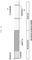
- FIGS. 1A and 1B illustrate a DRX operation.
- a terminal monitors the PDCCH in every subframe regardless of whether data is received in the connected state (indicated by reference numeral 110).
- C-DRX is configured as shown in FIG. 1B
- the terminal reduces battery consumption by turning off a RF transceiver if there is no data actually transmitted or received even in the connected state (indicated by reference numeral 130). Therefore, battery consumption can be reduced during an inactive time when the terminal enters the sleep mode.
- the Idle-mode DRX will be described with reference to FIG. 1A .
- paging occurs in the corresponding terminal.
- the terminal periodically wakes up, i.e., every paging DRX cycle 120, to monitor the PDCCH. If paging occurs, the terminal transitions to the connected state and receives data. If not, the terminal enters the sleep mode again.
- a DRX cycle having a long period may exist even in the RRC_Idle state.
- the terminal may operate in a DRX cycle having a long period.
- the length of a DRX cycle having long period may be an integer multiple of that of a short DRX cycle.
- the terminal obtains Idle-mode DRX configuration information from a higher-layer control message or an SIB2 message broadcasted by a base station.
- the terminal calculates a subframe for monitoring the PDCCH.
- the terminal in an idle state monitors only one subframe (PO) per paging DRX cycle.
- the connected-mode DRX will be described with reference to FIG. 1B .
- a DRX inactivity timer 140 and an RRC inactivity timer 150 are started.
- a DRX mode is started, and the terminal wakes up every DRX cycle and monitors the PDCCH for a predetermined duration (on-duration timer).
- the short DRX cycle 160 may be optionally configured. If short DRX is configured, the terminal starts with a short DRX cycle 160 and then transitions to a long DRX cycle 170 when the DRX mode is started.
- the length of the long DRX cycle may be configured as a multiple of that of the short DRX cycle, and the terminal wakes up more frequently in the short DRX cycle.
- the terminal transitions to the idle state and a paging DRX cycle starts.
- an RRC_Inactive state has been introduced in addition to the RRC_Idle and RRC_Connected states.
- a core network recognizes that the terminal is in a connected state and transmits a paging message to at least one base station with which the terminal is registered.
- at least one base station having received the paging message, generates a message related to the paging and transmits the message to the RAN-based area.
- the base station transmits a resume message, and the resume message may include information related to a UE AS context, for example, a UE AS context ID.
- the base station and the terminal may store UE AS context information.
- NR considers interworking with LTE.
- the most representative LTE/NR interworking is multi-RAT dual connectivity (MR-DC).
- MR-DC may be classified into the case in which LTE is a master node (MN) and the case in which NR is a MN.
- MN master node
- NR a MN
- a different network configuration is possible depending on the type of the core network. This is summarized in ⁇ Table 1> below.
- MN EPC 5GC Core eNB EN-DC(option 3) NGEN-DC(option 7) NR X NE-DC(option 4)
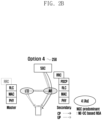
- FIGS. 2A and 2B The configuration of the system is shown in FIGS. 2A and 2B .
- FIGS. 2A and 2B illustrate the configuration of a multi-RAT dual connectivity according to the disclosure.
- FIG. 2C illustrates a radio protocol structure in LTE and 5G systems according to an embodiment of the disclosure.
- a wireless protocol in an LTE or 5G system includes packet data convergence protocols (hereinafter, PDCPs) 265 and 297, radio link controls (hereinafter, RLCs) 270 and 295, medium access controls (MACs) 275 and 290, and physical layers (PHYs) 280 and 285 in a terminal (eNB) and a base station (gNB), respectively.
- PDCPs packet data convergence protocols
- RLCs radio link controls
- MACs medium access controls
- PHYs physical layers
- intra-base station frequency aggregation technology for example, CA or DC
- LTE system LTE system
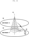
- FIG. 3A schematically illustrates an intra-base station frequency aggregation technology in an LTE/5G system according to an embodiment of the disclosure.
- one base station may generally transmit or receive signals through multiple carriers over several frequency bands. For example, when data is transmitted from a base station 301 through a carrier 303 having a forward center frequency of f1 and a carrier 302 having a forward center frequency of f3, one terminal conventionally transmits or receives data by using one of the two carriers.
- a terminal having frequency aggregation technology capability may concurrently transmit or receive data through multiple carriers.
- the base station 301 may increase the transmission rate of data for the terminal 304 by allocating more carriers according to the situation to the terminal 304 having the frequency aggregation technology capability.
- intra-eNB CA the aggregation of downlink carriers or aggregation of uplink carriers, through which one base station transmits or receives signals.
- aggregation of downlink carriers or aggregation of uplink carriers of different base stations may be required.
- FIG. 3A the intra-base station carrier aggregation operation in the LTE/5G system according to an embodiment of the disclosure has been described.
- inter-base station carrier aggregation technology in the LTE/5G system according to an embodiment of the disclosure will be described with reference to FIG. 3B .
- FIG. 3B schematically illustrates an inter-base station carrier aggregation operation according to an embodiment of the disclosure.
- base station 1 315 transmits or receives a signal through a carrier having a center frequency of f1 and base station 2 319 transmits or receives a signal through a carrier having a center frequency of f2
- base station 2 319 transmits or receives a signal through a carrier having a center frequency of f2
- a terminal 317 aggregates (combines) a carrier having a forward center frequency of f1 and a carrier having a forward center frequency of f2
- aggregation of carriers of two or more base stations by one terminal results.
- this is referred to as "inter-ENB/GNB carrier aggregation (or inter-base station CA)".
- inter-base station carrier aggregation is referred to as dual connectivity or multiple connectivity (hereinafter referred to as "DC").
- establishment of multiple connectivity or dual connectivity denotes that inter-base station carrier aggregation has been established, that one or more cell groups have been established, that a secondary cell group (SCG) has been established, that at least one secondary cell controlled by a base station rather than a serving base station has been established, that a primary SCell (PSCell) has been established, that a MAC entity for a secondary base station (secondary eNB, hereinafter referred to as "SeNB”, or secondary gNB, hereinafter referred to as "SgNB”) has been established, that two MAC entities have been established for a terminal, and the like.
- SCG secondary cell group
- PSCell primary SCell
- SgNB secondary gNB
- carrier aggregation may be understood as a terminal concurrently transmitting or receiving data through multiple cells.
- the maximum transmission rate and the number of aggregated carriers have a positive correlation.
- the feature whereby the terminal receives data through an arbitrary downlink carrier or transmits data through an arbitrary uplink carrier has the same meaning as the feature of transmitting or receiving data using a control channel and a data channel provided by a cell corresponding to a frequency band and a center frequency that characterize the carrier.
- carrier aggregation will be expressed as "a plurality of serving cells are configured", and terms such as "primary serving cell” (hereinafter referred to as PCell), a secondary serving cell (hereinafter referred to as an SCell), or "an activated serving cell” will be used.
- PCell primary serving cell
- SCell secondary serving cell
- an activated serving cell an activated serving cell
- a set of serving cells controlled by the same base station or a base station that is synchronized is defined as a cell group or a carrier group (hereinafter referred to as a "CG").
- the cell group is further divided into a master cell group (hereinafter referred to as an "MCG”) and a secondary cell group (SCG).
- MCG master cell group
- SCG secondary cell group
- the MCG denotes a set of serving cells controlled by a base station controlling a PCell (hereinafter, referred to as a master base station, MeNB, or MgNB), and the SCG denotes a set of serving cells, controlled by a base station other than the base station that controls the PCells, that is, a base station that controls only the SCells (hereinafter, a slave base station, SeNB, or SgNB).
- the base station notifies the terminal whether a specific serving cell belongs to the MCG or the SCG in the process of configuring the corresponding serving cell.
- PCell and SCell are terms indicating the type of serving cell configured in the terminal. There are some differences between the PCell and the SCell. For example, the PCell always remains in an active state, but in the case of the SCell, an active state and an inactive state are selectively operated according to an indication from the base station. The mobility of the terminal is controlled around the PCell, and the SCell may be understood as an additional serving cell for data transmission or reception.
- the PCell and SCell in the embodiments of the disclosure may be the PCell and SCell defined in the LTE standard 36.331 or 36.321.
- the PCell and SCell in the embodiments of the disclosure may be a PCell and an SCell defined in 5G standard 38.331 or 38.321.
- the situation in which a macro cell and a pico cell are mixed may be considered.
- the macro cell is a cell controlled by a macro base station and provides service in a relatively large area.
- the pico cell is a cell controlled by a SeNB, and typically provides service in a significantly narrower area than the macro cell.
- the area of the macro cell may be assumed to correspond to a radius of about 500 m, and the area of the pico cell may correspond to a radius on the order of tens of meters.
- the terms "pico cell” and "small cell” are interchangeably used.
- the macro cell may be an LTE or 5G base station (MeNB or MgNB)
- the pico cell may be a 5G or LTE base station (SeNB or SgNB).
- the 5G base station supporting the pico cell may use a frequency band of 6GHz or more.
- the situation in which a macro cell and a macro cell are mixed may be considered.
- the macro cell is a cell controlled by the macro base station, and provides service in a relatively large area.
- the macro cell may include an LTE base station (MeNB) and an LTE base station (SeNB).
- the macro cell may include an LTE (MeNB) base station and an NR base station (SgNB).
- the macro cell may include an NR (MgNB) base station and an LTE base station (SeNB).
- the macro cell may include an NR (MgNB) base station and an NR base station (SgNB).
- a serving cell 310 having a center frequency f1 is a serving cell belonging to MCG and a serving cell 320 having a center frequency f2 is a serving cell belonging to the SCG.
- MCG and SCG may be used instead of MCG and SCG for ease of understanding.
- terms such as “primary set” and “secondary set” or “primary carrier group” and “secondary carrier group” may be used. Even if different terms are used, it should be noted that only the terms used are different, and the meanings thereof are the same. The main purpose of use of these terms is to distinguish which cell is under the control of the base station controlling the PCell of a specific terminal, and the operation of the corresponding cell may differ depending on whether or not the cell is under the control of the base station controlling the PCell of a specific terminal.
- One or more SCGs may be configured in the terminal.
- the SCG may include multiple SCells, one of which has special properties.
- a terminal transmits not only a hybrid automatic repeat request (HARQ) for a PCell and channel state information (CSI) (hereinafter referred to as "CSI") through a physical uplink control channel (PUCCH) (hereinafter, referred to as "PUCCH”) of the PCell, but also HARQ feedback and CSI for an SCell.
- HARQ hybrid automatic repeat request
- PUCCH physical uplink control channel
- HARQ feedback should be delivered within a HARQ round trip time (RTT: hereinafter referred to as "RTT") (usually 8 ms), but the transmission delay between MeNB and SeNB may be longer than the HARQ RTT.
- RTT HARQ round trip time
- a PUCCH transmission resource is configured in one cell among SCells belonging to an SCG, and HARQ feedback and CSI for SCG SCells are transmitted through the PUCCH.
- the SCell above is called a PSCell.
- the inter-base station CA is interchangeably used with multiple connections.
- FIG. 3C schematically illustrates the connection structure of a PDCP entity according to an embodiment of the disclosure.
- a terminal may configure two RLC entities, as shown in reference numeral 340, to transmit or receive data to or from both a MeNB and a SeNB.
- QoS quality of service
- the terminal may establish an RLC entity only in the MeNB, as shown in reference numeral 335, to transmit or receive data using only the serving cell of the MeNB.
- the terminal may configure a bearer such that data is transmitted or received only to or from serving cells of the SeNB, as shown in reference numeral 365.
- a bearer through which data is transmitted or received only to or from the serving cell of the MeNB, as shown in reference numeral 335, is referred to as an MCG bearer
- a bearer through which data is transmitted or received only to or from the serving cell of the SeNB, as shown in reference numeral 365, is referred to as an SCG bearer.
- the PDCP entities of the MCG and SCG bearers are connected to one RLC entity, and PDCP entities of multi-bearer are connected to two RLC entities.
- RLC entities in which data is transmitted or received through the MCG are referred to as MCG RLCs 337 and 345
- RLC entities in which data is transmitted or received through the SCG are referred to as SCG RLCs 350 and 370.
- MACs 339 and 355 related to data transmission or reception through the MCG are referred to as MCG-MAC
- the MACs 360 and 375 related to data transmission and reception through the SCG are referred to as SCG-MAC.
- the MAC and RLC entities are connected using a logical channel, and a logical channel between MCG RLC and MCG-MAC is called an MCG logical channel, and a logical channel between an SCG RLC and an SCG-MAC is called an SCG logical channel.
- MCG logical channel a logical channel between MCG RLC and MCG-MAC
- SCG logical channel a logical channel between an SCG RLC and an SCG-MAC
- a macro cell area denotes an area in which only a macro cell signal is received without receiving a small cell signal
- a small cell area denotes an area in which both the macro cell signal and the small cell signal are received together.
- a bearer having a large amount of downlink data such as a file transfer protocol (FTP), among some bearers of the terminal, may be reconfigured as multiple bearers or SCG bearers from MCG bearers.
- FTP file transfer protocol
- the protocol layer may be applied to CA or DC in LTE communication system or a 5G communication system. That is, the protocol layer may be applied to CA or DC of LTE-LTE combination, LTE-NR combination, or NR-NR combination.
- a PDCP entity may be established in MeNB (or MgNB), and an RLC entity may be established in each of MeNB (or MgNB) and SeNB (or SgNB), and may be connected to the PDCP entity.
- the terminal may transmit or receive data to or from the MeNB (or MgNB) and the SeNB (or SgNB) (multi-bearer).
- each of the MeNB (or MgNB) and the SeNB (or SgNB) may establish a PDCP entity and an RLC entity to transmit or receive data to or from the terminal (MCG and SCG).
- a PDCP entity may be established in MgNB, and an RLC entity may be established in each of MgNB and SeNB, and may be connected to the PDCP entity. Accordingly, the terminal may transmit or receive data to or from the MgNB and the SeNB (multi bearer).
- each of the MgNB and SeNB may establish a PDCP entity and an RLC entity to transmit or receive data to or from the terminal (MCG and SCG). The same may be applied when the master node is a 5G base station.
- reference numerals 210, 220, and 230 illustrate the DC configuration of option 3 when the core network is an EPC (LTE network) and the master node is an LTE base station.
- EPC LTE network
- information of a control plane may be transmitted to a terminal through the LTE base station, which is the master node, while information of the user plane (UP) may be transmitted to the terminal through various paths.
- reference numeral 240 illustrates the DC configuration of option 7 when the core network is 5GC and the master node is an LTE base station.
- the CP signal may be transmitted to the terminal through the LTE base station, which is a master node, and the UP signal may be transmitted to the terminal through various paths.
- reference numeral 250 illustrates the DC configuration of option 4 when the core network is 5GC and the master node is a 5G base station.
- the CP signal may be transmitted to the terminal through the 5G base station, which is a master node, and the UP signal may be transmitted to the terminal through various paths.
- the DRX configuration is associated with the MAC, and MN and SN of the EN-DC may be configured independently, or the MN and SN may exchange the DRX configuration information with each other.
- EN-DC has one RRC state, which is based on MN RRC.
- a bandwidth below 6GHz and a bandwidth equal to or above 6GHz are connected via DC.
- the bandwidth below 6GHz and the bandwidth above 6GHz are in an RRC state and a MAC for each exists.
- both the definition and the operation of the MAC and RRC, defined in the MR-DC, may be equally applied.
- the secondary cell in the MR-DC may operate by distinguishing only the RRC connected state and the release state.
- SCells other than the PSCell may be activated and/or deactivated by the MAC CE.
- the PSCell enters an activated state at the time of configuration, and this state is maintained even when there is no data to be transmitted from the PSCell. Accordingly, the activated state of the PSCell is maintained until the base station transmits a secondary node release message. Since the terminal supplies full power (starting operation of an RF device such as a power amp) in the activated state of the PSCell, the terminal consumes more current than in the idle state. However, even when there is no data to be received through the PSCell, the activated state is maintained, and thus the terminal unnecessarily consumes electricity. Accordingly, a solution to the problem is required.
- the master node and the secondary node operate in one RRC state. That is, the secondary node operates in the same RRC state as the RRC state of the master node. Therefore, after the secondary node is activated once, even if no data is transmitted or received to or from the secondary node, the secondary node may be activated according to the state of the master node, and the power consumption of the terminal may be unnecessarily increased.
- the disclosure can also be applied in the dual-connectivity situation of LTE.
- the PSCell is described as an example, but the same description applies to an SCell.
- BWP bandwidth part
- the default BWP may be the same as the initial BWP, or an arbitrary resource may be configured in the base station.
- the default BWP may have the same frequency bandwidth as that of the initial BWP, or may be larger than the initial BWP.
- the default BWP may be a resource including at least one of a synchronization block (SS block) and remaining minimum system information (RSMI).
- SS block synchronization block
- RSMI remaining minimum system information
- the standard defines that, if the terminal does not receive scheduling before the BWP-inactivity timer (hereinafter referred to as BWP-InactivityTimer) expires in the state where the terminal is operating in a BWP other than the default BWP, the terminal deactivates the running BWP and activates the default BWP.
- BWP-InactivityTimer the BWP-inactivity timer
- the BWP-InactivityTimer is reset when a new BWP is activated or data is scheduled in the downlink. Resetting the timer may denote restarting the timer by returning the timer value to zero. If the default BWP is not explicitly set, the initial BWP may replace the default BWP.
- the terminal does not receive resources for at least one of a downlink and an uplink from the PSCell before the BWP-InactivityTimer expires, the terminal operates as the default BWP.
- the terminal in order to reduce energy consumption of a terminal in the state where a PSCell is in an activated state, it is possible to apply a DRX operation that has been applied in LTE.
- the terminal may enter a sleep state.
- the terminal that has entered the sleep state can periodically decode the PDCCH.
- the terminal since the terminal configures separate DRX configurations for the MN and the SN, the terminal may perform the DRX for the PSCell.
- the terminal may not apply power to at least a part of an RF module in the sleep state. In one embodiment, the terminal may not apply power to the power amp. In another embodiment, power may not be applied to the base band of the terminal. In another embodiment, the terminal may apply the power of at least a part of the RF module in accordance with the time at which the PDCCH is received, based on the C-DRX information received from the base station.
- the terminal If at least one resource allocation information of at least one of downlink and uplink for the terminal is transmitted through the PDCCH, the terminal remains in an active state, and if the resource allocation information for the terminal is not transmitted through the PDCCH, the terminal is changed back into a sleep state.
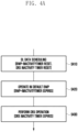
- FIG. 4A illustrates an operation sequence of a terminal according to an embodiment of the disclosure.
- the terminal may receive DL data scheduling in operation S410. Accordingly, the terminal that has received the DL data scheduling may reset the BWP-Inactivity Timer and the DRX inactivity Timer at the time of receiving scheduling. Resetting the timer may denote restarting the timer by returning the timer value to zero.
- the terminal operates as a default BWP in operation S420.
- the terminal After that, when the DRX inactivity timer expires, the terminal performs a DRX operation in operation S430.
- This embodiment describes the operation for the case where the BWP-InactivityTimer is configured to be shorter than the DRX inactivity timer. The details thereof will be described below with reference to FIG. 4 .
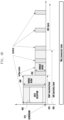
- FIG. 4B illustrates a DRX operation and a BWP change operation of a terminal according to an embodiment of the disclosure.
- the terminal may reset a BWP-Inactivity timer 420 and a DRX inactivity timer 430 at a time point 410 where the scheduling is received.
- the terminal may start a timer that is not running, or may restart the timer by returning the value of the timer that is running to zero.
- the case where the BWP-Inactivity timer 420 is configured to be longer than the DRX inactivity timer 430 will be described as an example.
- the terminal may operate in BW1 (indicated by reference numeral 440), and may be in an active state.
- the terminal receives data 460 according to the scheduling information. If the scheduling information is not received before the BWP-Inactivity timer 420 expires, the terminal may operate in a default BWP (BW2) (indicated by reference numeral 450).
- BW2 may denote a bandwidth smaller than BW1.
- the case where BW2 is the bandwidth of the default BWP is described as an example. However, the scope of the disclosure is not limited thereto, and as described above, it may include all cases where BW2 is configured to be smaller than BW1.
- the BW1 may include the case in which a default BWP operates in another bandwidth configured by the base station.
- the default BWP may include the case of the initial BWP.
- the default BWP may include the case including the SSB.
- the default BWP may not include the case including the SSB.
- the terminal may perform a DRX operation. That is, the terminal may wake up from the sleep mode according to the configured DRX cycle, and may monitor the PDCCH.
- FIG. 5 illustrates another operation sequence of a terminal according to an embodiment of the disclosure.
- the terminal may receive DL data scheduling in operation S510. Accordingly, the terminal that has received the DL data scheduling may reset the BWP-Inactivity Timer and the DRX inactivity timer at the time point at which the scheduling is received.
- the terminal After that, when the DRX inactivity timer expires, the terminal performs a DRX operation in operation S520.
- the terminal operates as a default BWP in operation S530.
- This embodiment describes the operation for the case where the BWP-InactivityTimer is configured to be longer than the DRX inactivity timer. The details thereof will be described below with reference to FIG. 6 .
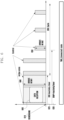
- FIG. 6 illustrates another DRX operation and a BWP change operation of a terminal according to an embodiment of the disclosure.
- the terminal may start a DRX inactivity timer 620 and a BWP-Inactivity timer 630 at the time point 610 of receiving the scheduling.
- the case where the BWP-Inactivity timer 630 is configured to be shorter than the DRX inactivity timer 620 will be described as an example.
- the terminal may operate in BW 1 (indicated by reference numeral 640) and may be in an activated state.
- the terminal receives data according to the scheduling information (indicated by reference numeral 660).
- the terminal may start the DRX operation. That is, the terminal wakes up according to the configured DRX cycle to monitor the PDCCH.
- the terminal may operate in a default BWP (BW2) (indicated by reference numeral 650).
- BW2 may denote a BW smaller than BW1.
- BW1 may include the case where the BW of the default BWP operates as another BW configured by a base station.
- the default BWP may include the case of an initial BWP.
- the default BWP may include the case including the SSB.
- the default BWP may not include the case including the SSB.
- the terminal may receive a secondary release message from the base station to release the terminal configuration for the secondary node (SN). Therefore, the disclosure further proposes a method for transmitting a release request message to the base station by the terminal.
- the above method should be used when it is determined that data will not be transmitted for a predetermined period of time. Therefore, a method for calculating the time point at which to transmit a release request message is proposed.
- FIGS. 7A and 7B illustrate a method for requesting release of a secondary node by a terminal according to an embodiment of the disclosure.
- the terminal may transmit a secondary node release request message to a master node in operation S710. That is, when it is determined that there is no data to be transmitted or received through the PSCell or the SCell, the terminal may request the release of the secondary node by transmitting the above message in order to reduce power consumption by the terminal.
- the terminal may use at least one of messages of a physical (PHY) layer, a media access control (MAC) layer, or a radio resource control (RRC) layer through a resource allocated by the master node. Details thereof will be described later.
- PHY physical
- MAC media access control
- RRC radio resource control
- the master node may perform the release procedure of the secondary cell in operation S720, and may transmit an RRCConnectionReconfiguration message to the terminal in operation S730.
- the terminal may transmit a secondary node release request message to the secondary node in operation S740. That is, unlike FIG. 7A , the terminal may directly transmit the secondary node release request to the secondary node using at least one of messages of the PHY, MAC, and RRC layers through the resources allocated by the secondary node.
- the secondary node may transmit the request to the master node, and the master node may perform the secondary node release procedure in operation S750.
- the master node may transmit an RRCConnectionReconfiguration message to the UE.
- the terminal may transmit a "Secondary Node Release Request” by transmitting at least one of RRC signals already defined in RRC to the base station.
- a method for "Secondary Node Release Request” is possible through an RRCConnectionReestablishmentRequest message.
- a method of adding a new RRC message for "Secondary Node Release Request” is also possible.
- the terminal when there is no allocated uplink (UL) resource, the terminal requests UL resources from the base station in order to perform RRC transmission and transmits an RRC message (a secondary node release message) using the allocated resource.
- the operation of the DRX inactivity timer, the BWP inactivity timer, or the data inactivity timer may not be affected.
- the terminal may perform the RRC message (secondary node release message) transmission using the corresponding resource.
- the allocated UL resource may be one of a granted resource, a grant-free type 1 resource, and a grant-free type 2 resource.
- the terminal may transmit a "Secondary Node Release Request" by transmitting at least one of MAC signals already defined in MAC to the base station.
- a method for "Secondary Node Release request" is possible through the MAC CE. For example, it is possible to add an ID for "Secondary Node Release Request" to an LCG ID list included in the MAC CE.
- the terminal requests UL resources from the base station in order to perform MAC CE transmission and performs MAC CE transmission using the allocated resources.
- the operation of the DRX inactivity timer, the BWP inactivity timer, or the data inactivity timer may not be affected.
- the terminal may perform MAC CE transmission using the corresponding resource.
- the allocated UL resource may be one of a granted resource, a grant-free type 1 resource, and a grant-free type 2 resource.
- the terminal may transmit a "Secondary Node Release Request" by transmitting at least one of PHY signals defined by the PHY to the base station.
- a method of using the SR defined in the PHY of the NR is possible.
- a method of newly defining a logical ID for a "Secondary Node Release Request" and including the logical ID in an SR configuration is possible.
- the terminal transmits an SR signal to the SR resource associated with the designated logical ID and transmits a "Secondary Node Release Request" message.
- a method in which when there is a UL-SCH resource allocated to the terminal in the RRC_CONNECTED state, in the case of receiving the SR from the terminal through the logical ID associated with the UL-SCH resource, the base station interprets the SR as "Secondary Node Release Request" is possible. That is, when there is an UL-SCH resource allocated in the RRC_CONNECTED state, the terminal transmits an SR signal through a logical ID associated with the UL-SCH resource and transmits a "Secondary Node Release Request" message.
- a method of transmitting a "Secondary Node Release Request" message in addition to the SR resource configured in the SR configuration is possible.
- the terminal may add 1 bit for transmission of the "Secondary Node Release Request” message to the SR configuration to indicate whether the request is possible using the corresponding SR resource.
- the terminal when it is indicated that the request is possible using an SR resource, when there is an UL-SCH resource allocated in the RRC_CONNECTED state, the terminal transmits an SR signal through a logical ID associated with the UL-SCH resource to transmit a "Secondary Node Release Request" message.
- the terminal when it is indicated that the request is possible through the SR resource, the terminal transmits a signal (phase change, bit information change, etc.) which differs from the SR signal through the logical ID associated with the UL-SCH resource, and transmits a "Secondary Node Release request" message.
- the terminal needs to be able to calculate the time point at which to transmit the message "Secondary Node Release Request". Accordingly, a process of determining, by the terminal, that the connection with the SN is no longer needed is required.
- the terminal may make a determination based on whether an APP requiring data transmission through the SN is running. More specifically, for example, when an AR APP is terminated in the situation in which data is received through the SN (e.g., a 5G network) for the AR APP, the terminal may determine that the connection with the SN is not necessary.
- the terminal may also perform the determination in a module included in the AP.
- the terminal may perform the determination in a module included in the CP. More specifically, it is possible to perform the determination in the PDCP layer or the RRC layer.
- the terminal may determine the time point at which to release SN based on information received from the MN.
- timer information for example, information related to datainactivitytimer
- the terminal starts the datainactivitytimer for the SN at the time point at which the SN receives scheduling. Further, if the SN does not receive resource scheduling for the downlink or uplink before the timer becomes to have a value equal to the expiration value of the datainactivitytimer received from the MN (that is, before the datainactivitytimer of the SN expires), the terminal may determine that it is no longer necessary to hold the SN, and may transmit a "Secondary Node Release Request" message. To this end, the terminal needs to include datainactivitytimer for SN release separately from datainactivitytimer for the MN.
- a method of directly indicating, by the MN or the SN, the time point at which to release the SN is possible.
- the information (information relating to the time point at which to release the SN) may be included in a message (for example, RRCConnectionReconfiguration) transmitted for SN addition or SN Modification.
- a method in which the above information is included in system information transmitted from the SN or the MN is possible.
- a method of transmitting information related to a datainactivitytimer for transmission of SN release to the terminal is possible.
- the terminal starts (or resets) the datainactivitytimer for the SN release at the time point at which the SN receives scheduling. Further, if the SN does not receive resource scheduling for the downlink or uplink before the timer becomes to have a value equal to the expiration value of the datainactivitytimer received from the MN (that is, before the datainactivitytimer of the SN expires), the terminal determines that it is no longer necessary to hold the SN, and transmits a "Secondary Node Release Request" message. To this end, the terminal needs to include a separate timer for SN.
- the method of transmitting a "Secondary Node Release Request" message may be performed in combination with methods described above. Details thereof will be described with reference to FIGS. 8 to 9 . However, although not shown in the drawings, a process of operating in a default BWP or a process of operating in a DRX cycle may not be included.
- FIGS. 8 illustrate an operation sequence in which a terminal transmits a secondary node release request message according to an embodiment of the disclosure.
- Operations S810 to S830 of FIG. 8A are the same as operations S310 to S330 of FIG. 3
- operations S850 to S870 of FIG. 8B are the same as operations S340 to S360 of FIG. 3 .
- the terminal may transmit a secondary node release request to the base station in operation S840 or operation S880.
- the terminal may transmit the secondary node release request to the base station when the longer timer among the BWP-InactivityTimer and the DRX inactivity timer expires.
- the terminal defined above may transmit the secondary node release request to the base station when a timer for SN Release (at least one of a datainactivitytimer received from MN, a separate timer for SN release, and a datainactivitytimer received from SN) expires.
- the terminal may transmit the secondary node release request to the base station when one of the BWP-InactivityTimer and the DRX inactivity timer expires.
- a process of operating in a default BWP or a process of operating in a DRX cycle may not be included.
- a timer for switching from the RRC_CONNECTED state to the RRC_IDLE state may be configured.
- the terminal may transmit the secondary node release request to the base station.
- FIGS. 9A and 9B illustrate a method for transmitting a secondary node release request message by a terminal according to an embodiment of the disclosure.
- FIGS. 9A and 9B may be seen to operate similarly to FIGS. 3 and 5 , respectively.
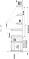
- FIGS. 9A and 9B illustrate the case where a data inactivity timer is further configured. Accordingly, referring to FIGS. 9A and 9B , when data inactivity timers 910 and 930 expire, the terminal may transmit a release request message (indicated by reference numerals 920 and 940).
- the terminal does not transmit the release request even when the datainactivity timer expires.
- the terminal may transmit the release request when at least one timer among the BWP-inactivityTimer and the DRX inactivityTimer expires or when the timer configured to be longer among the BWP-inactivityTimer and the DRX inactivityTimer expires.
- the terminal may request the base station to change the terminal into the RRC_IDLE state. That is, the disclosure proposes a method for transmitting an RRC Connection Release request message by a terminal to a base station. In order to reconnect the released MN and the SN, connection through RRC signaling needs to be performed. Therefore, the method should be used when it is determined that there is no data transmission for a predetermined period of time. Therefore, the disclosure proposes a method for calculating a time point at which to transmit a release request message.
- FIG. 10 illustrates a method for requesting an RRC connection release by a terminal according to an embodiment of the disclosure.
- the terminal may transmit an RRC connection release request message to the MN in operation S1010. That is, when it is determined that there is no data to be transmitted or received through the MN and the SN, the terminal may request the release of the secondary node by transmitting the above message to reduce the power consumption by the terminal.
- the terminal may use at least one of messages of the PHY, MAC, and RRC layer through resources allocated by a master node, since the details are the same as those set forth above, and will be omitted below.
- the terminal needs to be able to calculate the time point at which the "RRC connection release request" message is transmitted. Accordingly, the terminal requires a process of determining that the connection between the MN and the SN is no longer needed. That is, the terminal may make a determination based on whether or not an APP requiring data transmission is executed. The details are the same as those set forth above.
- the terminal may determine the time point at which the RRC connection is to be released based on the information received from the MN.
- timer information for example, information related to datainactivitytimer
- the terminal starts a timer at the time point at which the MN and SN receive final scheduling.
- the terminal may determine that it is no longer necessary to hold the MN and SN, and may transmit a "Secondary Node Release Request" message.
- the terminal may transmit the RRC connection release request message by combining the above descriptions, and may not include a process of operating in a default BWP or a process of operating in a DRX cycle.
- the secondary node release request of FIGS. 8 to 9 may be replaced with the RRC connection release request.
- FIGS. 11A and 11B illustrate an operation sequence in which a terminal transmits an RRC connection release request message according to an embodiment of the disclosure.
- operations S1110 to S1130 are the same as operations S810 to S830
- operations S1150 to S170 in FIG. 11B are the same as operations S850 to S870 in FIG. 8B .
- the terminal may transmit an RRC connection release request to the base station in operation S1140 or operation S1180.
- the details are the same as those set forth above, and will be omitted below.
- FIGS. 12A and 12B illustrate a method for transmitting an RRC connection release request message by a terminal according to an embodiment of the disclosure.
- FIGS. 12A and 12B can be seen to operate similarly to FIGS. 9A and 9B .
- the terminal may transmit an RRC connection release request message (indicated by reference numerals 1220 and 1240).
- RRC connection release request message indicated by reference numerals 1220 and 1240.
- an "RRC connection release request" message and a “secondary node release request” message may be signals having the same contents.
- an MN when an MN receives one signal, it may be interpreted as an "RRC connection release request", and when an SN receives one signal, it may be interpreted as a "secondary node release request".
- the two messages may be defined independently of each other, and may include different contents.
- a method in which one signal includes both messages but is separated by bit, bit map, or ID values is possible.
- the terminal even when there is data transmitted or received through the SN in the MR-DC, if the terminal is changed to the RRC_IDLE state, since the communication between the terminal and the SN may be stopped, the RRC _CONNECTED state of the terminal needs to be maintained.
- the RRC state of the terminal operates based on the RRC state of the MN
- the case where the RRC state of the MN transitions to RRC_IDLE may occur.
- a method for preventing this is proposed.
- the RRC of the MN transitions to RRC_IDLE.
- the connected DRX operates, power supply to modules that are not associated with the SN among modules associated with the MN may be stopped.
- the datainactivitytimer expires because there is no downlink data, the terminal and the base station transition to RRC IDLE.
- the datainactivitytimer may be reset or restarted.
- the disclosure proposes a method by a terminal for preventing the datainactivitytimer of the base station from expiring. According to at least one of the methods described below, the terminal intends to prevent the MN from transitioning to RRC_IDLE.
- the terminal may transmit at least one of RRC signals defined in RRC to the base station to maintain the MN in the RRC_CONNECTED state. According to an embodiment, the terminal may transmit an RRCConnectionReestablishmentRequest message.
- the base station When the RRCConnectionReestablishmentRequest is received in the RRC_CONNECTED state, the base station transmits an RRC ConnectionReestablishment message in response thereto, and thus has the effect of resetting the datainactivitytimer.
- the request message may include information indicating that the MN is a request message for maintaining the RRC_CONNECTED state due to the SN. Therefore, when the base station identifies that the request message is for maintaining the RRC_CONNECTED state, only the datainactivitytimer may be reset without transmitting a separate response message for the request.
- the terminal may request a UL resource from the base station in order to transmit the RRC message, and may transmit the RRC message using the allocated resource.
- the operation of the DRX inactivity timer, the BWP inactivity timer, or the data inactivity timer may not be affected.
- the terminal may transmit an RRC message using the corresponding resource.
- the allocated UL resource may be one of a granted resource, a grant-free type 1 resource, and a grant-free type 2 resource.
- a terminal can determine that it is connected through EN-DC, a method of transmitting an arbitrary message to LTE in a higher layer of the terminal is possible. It is also possible to generate a message in a TCP layer of the terminal. Alternatively, it is also possible to generate a message in an application layer of the terminal. For example, it is also possible to transmit a ping message to LTE through a well-known external server (e.g., a www.google.com server).
- a well-known external server e.g., a www.google.com server
- the terminal when there is no allocated UL resource, the terminal requests the UL resource from the base station in order to transmit higher-layer messages, and transmits the higher-layer messages by using the allocated resource.
- the operation of the DRX inactivity timer, the BWP inactivity timer, or the data inactivity timer may not be affected.
- the terminal may transmit a higher-layer message using the corresponding resource.
- the allocated UL resource may be one of a granted resource, a grant-free type 1 resource, and a grant-free type 2 resource.
- the terminal may transmit the MAC CE message to the base station to allow the MN to be maintained in an RRC_CONNECTED state.
- the terminal may transmit one of predefined MAC CE messages.
- the base station transmits a response message corresponding to each MAC CE transmitted by the terminal in response thereto, and thus has the effect of resetting the datainactivitytimer.
- the request message may include information indicating that the MN needs to be maintained in the RRC_CONNECTED state due to the SN. Therefore, even when the base station does not transmit a separate response message for the request, the datainactivitytimer may be reset.
- the terminal may request the UL resource from the base station in order to transmit the MAC CE message, and may transmit the MAC CE message using the allocated resource.
- the operation of the DRX inactivity timer, the BWP inactivity timer, or the data inactivity timer may not be affected.
- the terminal may perform the MAC CE message transmission using the corresponding resource.
- the allocated UL resource may be one of a granted resource, a grant-free type 1 resource, and a grant-free type 2 resource.
- the MAC CE when received in the MAC layer, it can be defined in the standard as shown in ⁇ Table 2> below so that at least one of start and restart of the data inactivity timer can be performed.
- the above method does not need to operate in every network.
- the terminal since there may also be a base station in which the problem raised above occurs, the terminal needs to distinguish the same in order to determine whether to perform the operation described above. Therefore, a method of distinguishing this is proposed below.
- a determination method based on information of a base station camped on by a terminal is possible.
- the terminal may identify the operation state of the corresponding network or the base station based on a global cell ID included in the system information transmitted from the base station or the MCC/MNC.
- the network information having a problem described above may be stored in the terminal in advance, and the terminal may change operations according to the identified system information.
- the terminal when the terminal is switched to RRC_IDLE during data transmission through the SN, it is also possible to store the system information of the base station in the DB to update the information.
- the DB may be stored in a separate server inside the terminal or outside the terminal.
- a bandwidth below 6GHz and a bandwidth above 6GHz are connected to DC.
- the bandwidth below 6GHz and the bandwidth above 6GHz are in an RRC state and a MAC for each exists.
- both the definition and the operation of the MAC and RRC defined in MR-DC may be equally applied.
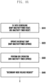
- FIG. 13 illustrates an operation sequence of a terminal according to an embodiment of the disclosure.
- a terminal may determine to release a connection with a base station or node.
- the release may include release of a connection with a secondary node or release of connections both with a master node and with the secondary node.
- the terminal may determine whether to perform connection release using the above-described method, and a detailed description thereof will thus be omitted.
- the terminal may generate a connection release request message.
- the terminal may generate an RRC message to release a connection with the secondary node or a connection with both the master node and the secondary node.
- the RRC message may be a type obtained by including a predetermined number of bits (for example, 1 bit) in a previously defined message (for example, an RRCconnectionReestablishment request) or a separate message for the request may be defined.
- the terminal may generate a message that can be transmitted in the MAC layer or a message that can be transmitted in the PHY layer.
- the terminal may transmit the message to the base station and request release of a connection with the base station.
- FIG. 14 illustrates an operation sequence of a base station according to an embodiment of the disclosure.
- the base station may transmit configuration information to a terminal in operation S1410.
- the configuration information may include the timer information described above, and the configuration information may be transmitted to the terminal through system information or RRC signaling.
- the base station may transmit scheduling information. If there is data to be transmitted to the terminal, the base station may transmit the scheduling information, and may transmit data according to the scheduling information.
- the base station may receive a connection release request message from the terminal.
- the base station may receive a connection release request message from the terminal based on the time point at which the scheduling information is transmitted and a timer value configured by the base station.
- the connection release request message may be received according to an application executed in the terminal. The time point at which to receive the connection release request message is the same as that described above, and will be omitted below.
- the base station may receive the connection release request message through at least one of the RRC, MAC, and PHY messages.
- the details of the connection release request message are the same as described above.
- the base station may release the connection with the terminal in operation S1440.
- the base station may release a connection between the secondary node and the terminal, or may release the connection both between the master node and the terminal and between the secondary node and the terminal according to the connection release request message of the terminal.
- FIG. 15 illustrates the structure of a terminal according to an embodiment of the disclosure.
- the terminal may include a transceiver 1510, a controller 1520, and a storage 1530.
- the controller may be defined as a circuit, an application-specific integrated circuit, or at least one processor.
- the transceiver 1510 may transmit a signal to or from another network entity.
- the transceiver 1510 may transmit, for example, a connection release request message to the base station.
- the controller 1520 may control the overall operation of the terminal according to the embodiment proposed by the disclosure.
- the controller 1520 may control signal flow between blocks in order to perform operations according to the flowchart described above.
- the storage 1530 may store at least one of information transmitted or received through the transceiver 1510 and information generated through the controller 1520.
- FIG. 16 illustrates the structure of a base station according to an embodiment of the disclosure.
- the base station may include a transceiver 1610, a controller 1620, and a storage 1630.
- the controller may be defined as a circuit, an application-specific integrated circuit, or at least one processor.
- the transceiver 1610 may transmit or receive a signal to or from another network entity.
- the transceiver 1610 may receive, for example, a connection release request message from the terminal.
- the controller 1620 may control the overall operation of the base station according to the embodiment proposed by the disclosure.
- the controller 1620 may control signal flow between blocks in order to perform operations according to the flowchart described above.
- the storage 1630 may store at least one of information transmitted or received through the transceiver 1610 and information generated through the controller 1620.
Landscapes
- Engineering & Computer Science (AREA)
- Computer Networks & Wireless Communication (AREA)
- Signal Processing (AREA)
- Mobile Radio Communication Systems (AREA)
Claims (8)
- Verfahren durch ein Endgerät, das gleichzeitig mit einem Masterknoten und einem Sekundärknoten in einem Drahtloskommunikationssystem verbunden ist, wobei das Verfahren Folgendes umfasst:Einstellen eines ersten Dateninaktivitäts-Timers für den Sekundärknoten;Zurücksetzen des ersten Dateninaktivitäts-Timers basierend darauf, dass der Sekundärknoten eine Planung empfängt; undÜbertragen eines Signals zum Zurücksetzen eines sekundären Dateninaktivitäts-Timers für den Masterknoten an den Masterknoten,wobei, falls das Endgerät feststellt, dass der erste Dateninaktivitäts-Timer abgelaufen ist, das Verfahren ferner Folgendes umfasst:Übertragen einer Sekundärknoten-Freigabenachricht an mindestens einen von dem Masterknoten und dem Sekundärknoten,und wobei, falls der Masterknoten feststellt, dass der sekundäre Dateninaktivitäts-Timer abgelaufen ist, das Endgerät und der Masterknoten in einen RRC-Ruhezustand übergehen.
- Verfahren nach Anspruch 1, wobei die Sekundärknoten-Freigabenachricht eine Radio-Resource-Control(RRC)-Nachricht enthält, die Bitinformationen enthält, die eine Freigabe einer Verbindung mit dem Sekundärknoten angeben.
- Verfahren durch eine Basisstation in einem Drahtloskommunikationssystem, wobei das Verfahren Folgendes umfasst:Übertragen von Konfigurationsinformationen, die Timer-Informationen zu einem ersten Dateninaktivitäts-Timer enthalten, an ein Endgerät, das gleichzeitig mit einem Masterknoten und einem Sekundärknoten verbunden ist;Einstellen eines sekundären Dateninaktivitäts-Timers für den Masterknoten;Übertragen von Planungsinformationen an das Endgerät;Zurücksetzen des sekundären Dateninaktivitäts-Timers als Reaktion auf ein Empfangen eines Signals zum Zurücksetzen des sekundären Dateninaktivitäts-Timers von dem Endgerät;Empfangen einer Sekundärknoten-Freigabeanforderungsnachricht zum Anfordern einer Freigabe einer Verbindung mit dem Sekundärknoten gemäß einem Ablauf des ersten Dateninaktivitäts-Timers; undFreigeben einer Verbindung zwischen dem Endgerät und dem Sekundärknoten,wobei, falls der sekundäre Dateninaktivitäts-Timer abläuft, das Endgerät und der Masterknoten in einen RRC-Ruhezustand übergehen.
- Verfahren nach Anspruch 3, wobei die Sekundärknoten-Freigabenachricht eine Radio-Resource-Control(RRC)-Nachricht enthält, die Bitinformationen enthält, die eine Freigabe einer Verbindung mit dem Sekundärknoten angeben.
- Endgerät, das gleichzeitig mit einem Masterknoten und einem Sekundärknoten in einem Drahtloskommunikationssystem verbunden ist, wobei das Endgerät Folgendes umfasst:einen Sendeempfänger; undeine Steuerung, die zu Folgendem konfiguriert ist:Einstellen eines ersten Dateninaktivitäts-Timers für den Sekundärknoten;Zurücksetzen des ersten Dateninaktivitäts-Timers basierend darauf, dass der Sekundärknoten eine Planung empfängt; undÜbertragen eines Signals zum Zurücksetzen eines sekundären Dateninaktivitäts-Timers für den Masterknoten an den Masterknoten;wobei, wenn das Endgerät feststellt, dass der erste Dateninaktivitäts-Timer abgelaufen ist, die Steuerung ferner zu Folgendem konfiguriert ist:Übertragen einer Sekundärknoten-Freigabeanforderungsnachricht an mindestens einen von dem Masterknoten und dem Sekundärknoten,und wobei, falls der Masterknoten feststellt, dass der sekundäre Dateninaktivitäts-Timer abgelaufen ist, das Endgerät und der Masterknoten in einen RRC-Ruhezustand übergehen.
- Endgerät nach Anspruch 5, wobei die Sekundärknoten-Freigabenachricht eine Radio-Resource-Control(RRC)-Nachricht enthält, die Bitinformationen enthält, die eine Freigabe einer Verbindung mit dem Sekundärknoten angeben.
- Basisstation in einem Drahtloskommunikationssystem, wobei die Basisstation Folgendes umfasst:einen Sendeempfänger; undeine Steuerung, die zu Folgendem konfiguriert ist:Übertragen von Konfigurationsinformationen, die Timer-Informationen zu einem ersten Dateninaktivitäts-Timer enthalten, an ein Endgerät, das gleichzeitig mit einem Masterknoten und einem Sekundärknoten verbunden ist,Einstellen eines sekundären Dateninaktivitäts-Timers,Übertragen von Planungsinformationen an das Endgerät,Zurücksetzen des sekundären Dateninaktivitäts-Timers als Reaktion auf ein Empfangen eines Signals zum Zurücksetzen des sekundären Dateninaktivitäts-Timers von dem Endgerät,Empfangen einer Sekundärknoten-Freigabeanforderungsnachricht zum Anfordern einer Freigabe einer Verbindung mit dem Sekundärknoten gemäß einem Ablauf des ersten Dateninaktivitäts-Timers, undFreigeben einer Verbindung zwischen dem Endgerät und dem Sekundärknoten, wobei, falls der sekundäre Dateninaktivitäts-Timer abläuft, das Endgerät und der Masterknoten in einen RRC-Ruhezustand übergehen.
- Basisstation nach Anspruch 7, wobei die Sekundärknoten-Freigabenachricht eine Radio-Resource-Control(RRC)-Nachricht enthält, die Bitinformationen enthält, die eine Freigabe einer Verbindung mit dem Sekundärknoten angeben.
Applications Claiming Priority (2)
| Application Number | Priority Date | Filing Date | Title |
|---|---|---|---|
| KR1020180059233A KR102544861B1 (ko) | 2018-05-24 | 2018-05-24 | 무선 통신 시스템에서 단말의 전력 소모 감소 방법 및 장치 |
| PCT/KR2019/005866 WO2019225900A1 (ko) | 2018-05-24 | 2019-05-16 | 무선 통신 시스템에서 단말의 전력 소모 감소 방법 및 장치 |
Publications (3)
| Publication Number | Publication Date |
|---|---|
| EP3758437A1 EP3758437A1 (de) | 2020-12-30 |
| EP3758437A4 EP3758437A4 (de) | 2021-05-12 |
| EP3758437B1 true EP3758437B1 (de) | 2024-08-28 |
Family
ID=68616432
Family Applications (1)
| Application Number | Title | Priority Date | Filing Date |
|---|---|---|---|
| EP19806692.0A Active EP3758437B1 (de) | 2018-05-24 | 2019-05-16 | Verfahren und vorrichtung zur reduzierung des leistungsverbrauchs durch ein endgerät in einem drahtloskommunikationssystem |
Country Status (5)
| Country | Link |
|---|---|
| US (1) | US11589416B2 (de) |
| EP (1) | EP3758437B1 (de) |
| KR (1) | KR102544861B1 (de) |
| CN (1) | CN112166646B (de) |
| WO (1) | WO2019225900A1 (de) |
Families Citing this family (11)
| Publication number | Priority date | Publication date | Assignee | Title |
|---|---|---|---|---|
| CN110830200B (zh) * | 2018-08-09 | 2021-09-07 | 华为技术有限公司 | 一种带宽部分处理方法及装置 |
| WO2020194192A1 (en) * | 2019-03-28 | 2020-10-01 | Nokia Technologies Oy | Bandwith part inactivity timer for unlicensed spectrum operations |
| US11601880B2 (en) * | 2019-05-01 | 2023-03-07 | Qualcomm Incorporated | Power management for a user equipment in a multi-radio connectivity mode or carrier aggregation mode |
| BR112022026947A2 (pt) * | 2020-06-30 | 2023-01-24 | Lenovo Singapore Pte Ltd | Configurar medições de posicionamento energeticamente eficientes |
| EP4183222A1 (de) * | 2020-08-17 | 2023-05-24 | Nokia Technologies Oy | Duales konnektivitätsszenario für koordiniertes leave |
| EP4233479A4 (de) * | 2020-10-23 | 2024-04-10 | LG Electronics Inc. | Verfahren und vorrichtung zur energieeinsparung in einem drahtlosen kommunikationssystem |
| KR102645665B1 (ko) * | 2020-11-30 | 2024-03-11 | 엘지전자 주식회사 | 무선 통신 시스템에서 mbs 세션을 위한 데이터 비활성 타이머 처리를 위한 방법 및 장치 |
| CN114697946A (zh) * | 2020-12-25 | 2022-07-01 | 维沃移动通信有限公司 | 辅小区组状态信息的通知方法、装置及网络侧设备 |
| KR20220129895A (ko) | 2021-03-17 | 2022-09-26 | 삼성전자주식회사 | 무선 통신 시스템에서 자원 할당을 위한 장치 및 방법 |
| CN115707052A (zh) * | 2021-08-10 | 2023-02-17 | 中国电信股份有限公司 | 基于双连接配置的通信方法及相关设备 |
| KR20240056653A (ko) * | 2021-09-22 | 2024-04-30 | 베이징 시아오미 모바일 소프트웨어 컴퍼니 리미티드 | Bwp 전환 방법, 장치 및 저장 매체(bwp switching method and apparatus, and storage medium) |
Citations (1)
| Publication number | Priority date | Publication date | Assignee | Title |
|---|---|---|---|---|
| US20170127473A1 (en) * | 2014-06-24 | 2017-05-04 | Nokia Technologies Oy | Dual connectivity management |
Family Cites Families (35)
| Publication number | Priority date | Publication date | Assignee | Title |
|---|---|---|---|---|
| US7493391B2 (en) * | 2001-02-12 | 2009-02-17 | International Business Machines Corporation | System for automated session resource clean-up by determining whether server resources have been held by client longer than preset thresholds |
| EP1798998B1 (de) * | 2005-12-14 | 2011-06-15 | Research In Motion Limited | Verfahren und Gerät für Endgerätebasierte Funkmittelsteuerung in einem UMTS Netz |
| US8265034B2 (en) * | 2006-05-17 | 2012-09-11 | Research In Motion Limited | Method and system for a signaling connection release indication |
| CN106160992B (zh) * | 2010-02-12 | 2020-07-03 | 交互数字专利控股公司 | 增强无线发射/接收单元的小区边缘性能的方法及网络 |
| CN102202422B (zh) * | 2010-03-22 | 2014-01-01 | 华为技术有限公司 | 状态迁移方法和网络设备 |
| US8942151B2 (en) * | 2011-04-29 | 2015-01-27 | Blackberry Limited | Receiving messages in connection with LTE wakeup |
| EP2844023A4 (de) * | 2012-04-27 | 2015-12-02 | Mitsubishi Electric Corp | Kommunikationssystem |
| US9467941B2 (en) | 2012-06-07 | 2016-10-11 | Qualcomm Incorporated | Power based fast dormancy |
| US8995394B2 (en) * | 2012-06-15 | 2015-03-31 | Amazon Technologies, Inc. | System for fast dormancy on wireless networks |
| WO2014085980A1 (en) * | 2012-12-04 | 2014-06-12 | Qualcomm Incorporated | Apparatus and method for enhanced mobile power management |
| CN103906049B (zh) | 2012-12-28 | 2019-09-24 | 北京三星通信技术研究有限公司 | 一种同步辅小区和ue之间加密信息的方法 |
| KR101774134B1 (ko) * | 2013-04-04 | 2017-09-01 | 인터디지탈 패튼 홀딩스, 인크 | 오프로드를 통한 개선된 wlan 이용을 위한 3gpp wlan 상호작용을 위한 방법들 |
| JP6137405B2 (ja) * | 2013-04-11 | 2017-05-31 | 富士通株式会社 | Mac層エンティティの処理方法、ユーザ装置及び通信システム |
| EP2987385A2 (de) * | 2013-04-15 | 2016-02-24 | Interdigital Patent Holdings, Inc. | Schemata für diskontinuierlichen empfang für duale millimeterwellenlängen-konnektivität |
| JP6018300B2 (ja) * | 2013-05-10 | 2016-11-02 | 京セラ株式会社 | 通信制御方法、ユーザ端末及びプロセッサ |
| US9713142B2 (en) * | 2013-07-14 | 2017-07-18 | Lg Electronics Inc. | Method and apparatus for managing data radio bearers for dual connectivity in wireless communication system |
| US10194311B2 (en) * | 2013-09-13 | 2019-01-29 | Lg Electronics Inc. | Method for setting and updating tracking area in C-RAN and apparatus therefor |
| KR101802157B1 (ko) * | 2013-10-28 | 2017-12-28 | 엘지전자 주식회사 | 이종 네트워크에서 이중 연결 동작을 수행하기 위한 방법 및 장치 |
| US9661657B2 (en) * | 2013-11-27 | 2017-05-23 | Intel Corporation | TCP traffic adaptation in wireless systems |
| JP2017514367A (ja) * | 2014-03-28 | 2017-06-01 | 富士通株式会社 | ベアラ管理装置、方法及び通信システム |
| US20150282080A1 (en) * | 2014-03-28 | 2015-10-01 | Broadcom Corporation | System, device, and method for configuring dual drx cycles |
| CN106233805B (zh) * | 2014-04-28 | 2020-01-10 | 夏普株式会社 | 终端装置、基站装置、通信方法以及集成电路 |
| US10057937B2 (en) * | 2014-05-02 | 2018-08-21 | Nokia Solutions And Networks Oy | Communications via multiple access points |
| US20150334767A1 (en) * | 2014-05-13 | 2015-11-19 | Htc Corporation | Device of Handling Measurement Configuration |
| CN106576381B (zh) * | 2014-08-08 | 2020-10-02 | Lg电子株式会社 | 在无线通信系统中通知针对双连接的服务释放的方法和设备 |
| US10219317B2 (en) * | 2014-09-25 | 2019-02-26 | Lg Electronics Inc. | Method for handling of data transmission and reception for SeNB related bearer release at a user equipment in a dual connectivity system and device therefor |
| US10342066B2 (en) * | 2014-11-07 | 2019-07-02 | Nokia Solutions And Networks Oy | Method and apparatus for dual connectivity management |
| US10638377B2 (en) * | 2015-07-31 | 2020-04-28 | Nec Corporation | Base station apparatus for dual connectivity and method thereof |
| US10542469B2 (en) | 2015-08-21 | 2020-01-21 | Samsung Electronics Co., Ltd. | Apparatus and method for supporting handover with multi-connectivity in wireless communication system |
| KR102691637B1 (ko) * | 2015-08-21 | 2024-08-06 | 삼성전자 주식회사 | 무선 통신 시스템 내 단말의 통신 방법 및 장치 |
| WO2017052206A1 (ko) * | 2015-09-23 | 2017-03-30 | 주식회사 케이티 | 단말의 이동성 제어 방법 및 그 장치 |
| WO2017061317A1 (ja) * | 2015-10-06 | 2017-04-13 | 日本電気株式会社 | デュアルコネクティビティに関連する装置 |
| KR102358095B1 (ko) * | 2016-08-11 | 2022-02-04 | 삼성전자 주식회사 | 저전력 rrc 운용 방법 및 장치 |
| EP3322254A1 (de) * | 2016-11-11 | 2018-05-16 | Nokia Technologies Oy | Verbindungssteuerung zur dualen konnektivität und zusammenarbeit in drahtlosen netzwerken |
| EP3568946B1 (de) * | 2017-10-26 | 2025-03-19 | Ofinno, LLC | Inaktivitätstimer für bandbreitenteil |
-
2018
- 2018-05-24 KR KR1020180059233A patent/KR102544861B1/ko active Active
-
2019
- 2019-05-16 US US17/057,213 patent/US11589416B2/en active Active
- 2019-05-16 EP EP19806692.0A patent/EP3758437B1/de active Active
- 2019-05-16 WO PCT/KR2019/005866 patent/WO2019225900A1/ko not_active Ceased
- 2019-05-16 CN CN201980034702.2A patent/CN112166646B/zh active Active
Patent Citations (1)
| Publication number | Priority date | Publication date | Assignee | Title |
|---|---|---|---|---|
| US20170127473A1 (en) * | 2014-06-24 | 2017-05-04 | Nokia Technologies Oy | Dual connectivity management |
Also Published As
| Publication number | Publication date |
|---|---|
| KR20190134063A (ko) | 2019-12-04 |
| EP3758437A4 (de) | 2021-05-12 |
| KR102544861B1 (ko) | 2023-06-19 |
| US20210227623A1 (en) | 2021-07-22 |
| EP3758437A1 (de) | 2020-12-30 |
| US11589416B2 (en) | 2023-02-21 |
| CN112166646A (zh) | 2021-01-01 |
| CN112166646B (zh) | 2024-09-13 |
| WO2019225900A1 (ko) | 2019-11-28 |
Similar Documents
| Publication | Publication Date | Title |
|---|---|---|
| EP3758437B1 (de) | Verfahren und vorrichtung zur reduzierung des leistungsverbrauchs durch ein endgerät in einem drahtloskommunikationssystem | |
| US11109274B2 (en) | Method and apparatus for transmitting or receiving paging in wireless communication system | |
| JP7681758B2 (ja) | ダウンリンク制御チャネルのモニタリングに関するユーザ装置 | |
| EP3358879B1 (de) | Kommunikationsendgerät und verfahren zur kommunikation | |
| US20170366236A1 (en) | Method and apparatus for paging using beamforming in wireless communication system | |
| US10251084B2 (en) | Method for multi-rat scheduling and apparatus therefor in system in which heterogeneous wireless communication technologies are utilized | |
| EP3378249B1 (de) | Verfahren und vorrichtung zur verringerung eines signalisierungs-overhead und zur verringerung der batterie eines endgeräts | |
| US20200137685A1 (en) | Method and apparatus for transmitting and receiving a wake-up signal in a wireless communication system | |
| US10728951B2 (en) | Communications terminal, infrastructure equipment and methods for discontinuous reception, DRX | |
| KR102918486B1 (ko) | 동적 전력 공유 지원을 위한 파워 헤드룸 보고를 트리거링하는 방법 및 장치 | |
| US20250212114A1 (en) | Method, device, and system for power saving in wireless networks | |
| CN107889216B (zh) | 数据发送、接收方法及装置、基站、终端 | |
| US20260032589A1 (en) | Method and apparatus for wireless communication | |
| EP4018773B1 (de) | Verfahren zur planung mit inaktivität in sidelink-unicast | |
| KR20170017757A (ko) | 셀룰러 사물 인터넷 장치의 전력 절감을 위한 장치 및 방법 | |
| WO2025209765A1 (en) | Dynamic handling of on-demand sib1 transmission modes | |
| US20250338308A1 (en) | Method of wireless communication, user equipment and base-station for small data transmission, sdt | |
| KR20200071736A (ko) | 네트워크 액세스 우선 순위화 | |
| EP4516000A1 (de) | Handhabung kleiner datenübertragung | |
| EP4515999A1 (de) | Verfahren zur drahtlosen kommunikation, benutzergerät und basisstation | |
| US20250048264A1 (en) | Signal transmission method and communication apparatus | |
| US20240080773A1 (en) | Prioritizing cell selection in a user equipment | |
| WO2024171106A1 (en) | Main radio configuration indicator through low power wake up radio | |
| WO2025112678A1 (zh) | 通信方法及通信装置 | |
| KR20250025639A (ko) | 무선 네트워크의 불연속 데이터 송수신을 위한 방법, 디바이스, 및 시스템 |
Legal Events
| Date | Code | Title | Description |
|---|---|---|---|
| STAA | Information on the status of an ep patent application or granted ep patent |
Free format text: STATUS: THE INTERNATIONAL PUBLICATION HAS BEEN MADE |
|
| PUAI | Public reference made under article 153(3) epc to a published international application that has entered the european phase |
Free format text: ORIGINAL CODE: 0009012 |
|
| STAA | Information on the status of an ep patent application or granted ep patent |
Free format text: STATUS: REQUEST FOR EXAMINATION WAS MADE |
|
| 17P | Request for examination filed |
Effective date: 20200924 |
|
| AK | Designated contracting states |
Kind code of ref document: A1 Designated state(s): AL AT BE BG CH CY CZ DE DK EE ES FI FR GB GR HR HU IE IS IT LI LT LU LV MC MK MT NL NO PL PT RO RS SE SI SK SM TR |
|
| AX | Request for extension of the european patent |
Extension state: BA ME |
|
| A4 | Supplementary search report drawn up and despatched |
Effective date: 20210414 |
|
| RIC1 | Information provided on ipc code assigned before grant |
Ipc: H04W 76/38 20180101AFI20210408BHEP Ipc: H04W 52/02 20090101ALI20210408BHEP Ipc: H04W 88/08 20090101ALI20210408BHEP Ipc: H04W 76/15 20180101ALI20210408BHEP Ipc: H04W 76/28 20180101ALI20210408BHEP Ipc: H04W 76/30 20180101ALI20210408BHEP |
|
| DAV | Request for validation of the european patent (deleted) | ||
| DAX | Request for extension of the european patent (deleted) | ||
| STAA | Information on the status of an ep patent application or granted ep patent |
Free format text: STATUS: EXAMINATION IS IN PROGRESS |
|
| 17Q | First examination report despatched |
Effective date: 20230411 |
|
| GRAP | Despatch of communication of intention to grant a patent |
Free format text: ORIGINAL CODE: EPIDOSNIGR1 |
|
| STAA | Information on the status of an ep patent application or granted ep patent |
Free format text: STATUS: GRANT OF PATENT IS INTENDED |
|
| GRAS | Grant fee paid |
Free format text: ORIGINAL CODE: EPIDOSNIGR3 |
|
| INTG | Intention to grant announced |
Effective date: 20240618 |
|
| RIN1 | Information on inventor provided before grant (corrected) |
Inventor name: LEE, JANGBOK Inventor name: LEE, SOOMIN Inventor name: SHIN, SUNGHYUK Inventor name: PARK, HONGJU Inventor name: JUNG, EUICHANG Inventor name: YOON, SUHA Inventor name: PARK, SUYOUNG |
|
| GRAA | (expected) grant |
Free format text: ORIGINAL CODE: 0009210 |
|
| STAA | Information on the status of an ep patent application or granted ep patent |
Free format text: STATUS: THE PATENT HAS BEEN GRANTED |
|
| AK | Designated contracting states |
Kind code of ref document: B1 Designated state(s): AL AT BE BG CH CY CZ DE DK EE ES FI FR GB GR HR HU IE IS IT LI LT LU LV MC MK MT NL NO PL PT RO RS SE SI SK SM TR |
|
| REG | Reference to a national code |
Ref country code: GB Ref legal event code: FG4D |
|
| REG | Reference to a national code |
Ref country code: CH Ref legal event code: EP |
|
| REG | Reference to a national code |
Ref country code: DE Ref legal event code: R096 Ref document number: 602019057972 Country of ref document: DE |
|
| REG | Reference to a national code |
Ref country code: IE Ref legal event code: FG4D |
|
| REG | Reference to a national code |
Ref country code: LT Ref legal event code: MG9D |
|
| PG25 | Lapsed in a contracting state [announced via postgrant information from national office to epo] |
Ref country code: NO Free format text: LAPSE BECAUSE OF FAILURE TO SUBMIT A TRANSLATION OF THE DESCRIPTION OR TO PAY THE FEE WITHIN THE PRESCRIBED TIME-LIMIT Effective date: 20241128 |
|
| REG | Reference to a national code |
Ref country code: AT Ref legal event code: MK05 Ref document number: 1719299 Country of ref document: AT Kind code of ref document: T Effective date: 20240828 |
|
| PG25 | Lapsed in a contracting state [announced via postgrant information from national office to epo] |
Ref country code: NL Free format text: LAPSE BECAUSE OF FAILURE TO SUBMIT A TRANSLATION OF THE DESCRIPTION OR TO PAY THE FEE WITHIN THE PRESCRIBED TIME-LIMIT Effective date: 20240828 Ref country code: FI Free format text: LAPSE BECAUSE OF FAILURE TO SUBMIT A TRANSLATION OF THE DESCRIPTION OR TO PAY THE FEE WITHIN THE PRESCRIBED TIME-LIMIT Effective date: 20240828 Ref country code: PT Free format text: LAPSE BECAUSE OF FAILURE TO SUBMIT A TRANSLATION OF THE DESCRIPTION OR TO PAY THE FEE WITHIN THE PRESCRIBED TIME-LIMIT Effective date: 20241230 Ref country code: GR Free format text: LAPSE BECAUSE OF FAILURE TO SUBMIT A TRANSLATION OF THE DESCRIPTION OR TO PAY THE FEE WITHIN THE PRESCRIBED TIME-LIMIT Effective date: 20241129 Ref country code: PL Free format text: LAPSE BECAUSE OF FAILURE TO SUBMIT A TRANSLATION OF THE DESCRIPTION OR TO PAY THE FEE WITHIN THE PRESCRIBED TIME-LIMIT Effective date: 20240828 |
|
| PG25 | Lapsed in a contracting state [announced via postgrant information from national office to epo] |
Ref country code: BG Free format text: LAPSE BECAUSE OF FAILURE TO SUBMIT A TRANSLATION OF THE DESCRIPTION OR TO PAY THE FEE WITHIN THE PRESCRIBED TIME-LIMIT Effective date: 20240828 |
|
| PG25 | Lapsed in a contracting state [announced via postgrant information from national office to epo] |
Ref country code: LV Free format text: LAPSE BECAUSE OF FAILURE TO SUBMIT A TRANSLATION OF THE DESCRIPTION OR TO PAY THE FEE WITHIN THE PRESCRIBED TIME-LIMIT Effective date: 20240828 |
|
| REG | Reference to a national code |
Ref country code: NL Ref legal event code: MP Effective date: 20240828 |
|
| PG25 | Lapsed in a contracting state [announced via postgrant information from national office to epo] |
Ref country code: AT Free format text: LAPSE BECAUSE OF FAILURE TO SUBMIT A TRANSLATION OF THE DESCRIPTION OR TO PAY THE FEE WITHIN THE PRESCRIBED TIME-LIMIT Effective date: 20240828 Ref country code: IS Free format text: LAPSE BECAUSE OF FAILURE TO SUBMIT A TRANSLATION OF THE DESCRIPTION OR TO PAY THE FEE WITHIN THE PRESCRIBED TIME-LIMIT Effective date: 20241228 |
|
| PG25 | Lapsed in a contracting state [announced via postgrant information from national office to epo] |
Ref country code: HR Free format text: LAPSE BECAUSE OF FAILURE TO SUBMIT A TRANSLATION OF THE DESCRIPTION OR TO PAY THE FEE WITHIN THE PRESCRIBED TIME-LIMIT Effective date: 20240828 |
|
| PG25 | Lapsed in a contracting state [announced via postgrant information from national office to epo] |
Ref country code: ES Free format text: LAPSE BECAUSE OF FAILURE TO SUBMIT A TRANSLATION OF THE DESCRIPTION OR TO PAY THE FEE WITHIN THE PRESCRIBED TIME-LIMIT Effective date: 20240828 Ref country code: RS Free format text: LAPSE BECAUSE OF FAILURE TO SUBMIT A TRANSLATION OF THE DESCRIPTION OR TO PAY THE FEE WITHIN THE PRESCRIBED TIME-LIMIT Effective date: 20241128 |
|
| PG25 | Lapsed in a contracting state [announced via postgrant information from national office to epo] |
Ref country code: RS Free format text: LAPSE BECAUSE OF FAILURE TO SUBMIT A TRANSLATION OF THE DESCRIPTION OR TO PAY THE FEE WITHIN THE PRESCRIBED TIME-LIMIT Effective date: 20241128 Ref country code: PT Free format text: LAPSE BECAUSE OF FAILURE TO SUBMIT A TRANSLATION OF THE DESCRIPTION OR TO PAY THE FEE WITHIN THE PRESCRIBED TIME-LIMIT Effective date: 20241230 Ref country code: PL Free format text: LAPSE BECAUSE OF FAILURE TO SUBMIT A TRANSLATION OF THE DESCRIPTION OR TO PAY THE FEE WITHIN THE PRESCRIBED TIME-LIMIT Effective date: 20240828 Ref country code: NO Free format text: LAPSE BECAUSE OF FAILURE TO SUBMIT A TRANSLATION OF THE DESCRIPTION OR TO PAY THE FEE WITHIN THE PRESCRIBED TIME-LIMIT Effective date: 20241128 Ref country code: NL Free format text: LAPSE BECAUSE OF FAILURE TO SUBMIT A TRANSLATION OF THE DESCRIPTION OR TO PAY THE FEE WITHIN THE PRESCRIBED TIME-LIMIT Effective date: 20240828 Ref country code: LV Free format text: LAPSE BECAUSE OF FAILURE TO SUBMIT A TRANSLATION OF THE DESCRIPTION OR TO PAY THE FEE WITHIN THE PRESCRIBED TIME-LIMIT Effective date: 20240828 Ref country code: IS Free format text: LAPSE BECAUSE OF FAILURE TO SUBMIT A TRANSLATION OF THE DESCRIPTION OR TO PAY THE FEE WITHIN THE PRESCRIBED TIME-LIMIT Effective date: 20241228 Ref country code: HR Free format text: LAPSE BECAUSE OF FAILURE TO SUBMIT A TRANSLATION OF THE DESCRIPTION OR TO PAY THE FEE WITHIN THE PRESCRIBED TIME-LIMIT Effective date: 20240828 Ref country code: GR Free format text: LAPSE BECAUSE OF FAILURE TO SUBMIT A TRANSLATION OF THE DESCRIPTION OR TO PAY THE FEE WITHIN THE PRESCRIBED TIME-LIMIT Effective date: 20241129 Ref country code: FI Free format text: LAPSE BECAUSE OF FAILURE TO SUBMIT A TRANSLATION OF THE DESCRIPTION OR TO PAY THE FEE WITHIN THE PRESCRIBED TIME-LIMIT Effective date: 20240828 Ref country code: ES Free format text: LAPSE BECAUSE OF FAILURE TO SUBMIT A TRANSLATION OF THE DESCRIPTION OR TO PAY THE FEE WITHIN THE PRESCRIBED TIME-LIMIT Effective date: 20240828 Ref country code: BG Free format text: LAPSE BECAUSE OF FAILURE TO SUBMIT A TRANSLATION OF THE DESCRIPTION OR TO PAY THE FEE WITHIN THE PRESCRIBED TIME-LIMIT Effective date: 20240828 Ref country code: AT Free format text: LAPSE BECAUSE OF FAILURE TO SUBMIT A TRANSLATION OF THE DESCRIPTION OR TO PAY THE FEE WITHIN THE PRESCRIBED TIME-LIMIT Effective date: 20240828 |
|
| PG25 | Lapsed in a contracting state [announced via postgrant information from national office to epo] |
Ref country code: DK Free format text: LAPSE BECAUSE OF FAILURE TO SUBMIT A TRANSLATION OF THE DESCRIPTION OR TO PAY THE FEE WITHIN THE PRESCRIBED TIME-LIMIT Effective date: 20240828 Ref country code: SM Free format text: LAPSE BECAUSE OF FAILURE TO SUBMIT A TRANSLATION OF THE DESCRIPTION OR TO PAY THE FEE WITHIN THE PRESCRIBED TIME-LIMIT Effective date: 20240828 Ref country code: RO Free format text: LAPSE BECAUSE OF FAILURE TO SUBMIT A TRANSLATION OF THE DESCRIPTION OR TO PAY THE FEE WITHIN THE PRESCRIBED TIME-LIMIT Effective date: 20240828 |
|
| PG25 | Lapsed in a contracting state [announced via postgrant information from national office to epo] |
Ref country code: EE Free format text: LAPSE BECAUSE OF FAILURE TO SUBMIT A TRANSLATION OF THE DESCRIPTION OR TO PAY THE FEE WITHIN THE PRESCRIBED TIME-LIMIT Effective date: 20240828 |
|
| PG25 | Lapsed in a contracting state [announced via postgrant information from national office to epo] |
Ref country code: CZ Free format text: LAPSE BECAUSE OF FAILURE TO SUBMIT A TRANSLATION OF THE DESCRIPTION OR TO PAY THE FEE WITHIN THE PRESCRIBED TIME-LIMIT Effective date: 20240828 |
|
| PG25 | Lapsed in a contracting state [announced via postgrant information from national office to epo] |
Ref country code: SK Free format text: LAPSE BECAUSE OF FAILURE TO SUBMIT A TRANSLATION OF THE DESCRIPTION OR TO PAY THE FEE WITHIN THE PRESCRIBED TIME-LIMIT Effective date: 20240828 Ref country code: IT Free format text: LAPSE BECAUSE OF FAILURE TO SUBMIT A TRANSLATION OF THE DESCRIPTION OR TO PAY THE FEE WITHIN THE PRESCRIBED TIME-LIMIT Effective date: 20240828 |
|
| REG | Reference to a national code |
Ref country code: DE Ref legal event code: R097 Ref document number: 602019057972 Country of ref document: DE |
|
| PLBE | No opposition filed within time limit |
Free format text: ORIGINAL CODE: 0009261 |
|
| STAA | Information on the status of an ep patent application or granted ep patent |
Free format text: STATUS: NO OPPOSITION FILED WITHIN TIME LIMIT |
|
| PGFP | Annual fee paid to national office [announced via postgrant information from national office to epo] |
Ref country code: DE Payment date: 20250422 Year of fee payment: 7 |
|
| 26N | No opposition filed |
Effective date: 20250530 |
|
| PG25 | Lapsed in a contracting state [announced via postgrant information from national office to epo] |
Ref country code: SE Free format text: LAPSE BECAUSE OF FAILURE TO SUBMIT A TRANSLATION OF THE DESCRIPTION OR TO PAY THE FEE WITHIN THE PRESCRIBED TIME-LIMIT Effective date: 20240828 |
|
| REG | Reference to a national code |
Ref country code: CH Ref legal event code: H13 Free format text: ST27 STATUS EVENT CODE: U-0-0-H10-H13 (AS PROVIDED BY THE NATIONAL OFFICE) Effective date: 20251223 |
|
| PG25 | Lapsed in a contracting state [announced via postgrant information from national office to epo] |
Ref country code: LU Free format text: LAPSE BECAUSE OF NON-PAYMENT OF DUE FEES Effective date: 20250516 |
|
| PG25 | Lapsed in a contracting state [announced via postgrant information from national office to epo] |
Ref country code: CH Free format text: LAPSE BECAUSE OF NON-PAYMENT OF DUE FEES Effective date: 20250531 |
|
| GBPC | Gb: european patent ceased through non-payment of renewal fee |
Effective date: 20250516 |
|
| REG | Reference to a national code |
Ref country code: BE Ref legal event code: MM Effective date: 20250531 |
|
| PG25 | Lapsed in a contracting state [announced via postgrant information from national office to epo] |
Ref country code: MC Free format text: LAPSE BECAUSE OF FAILURE TO SUBMIT A TRANSLATION OF THE DESCRIPTION OR TO PAY THE FEE WITHIN THE PRESCRIBED TIME-LIMIT Effective date: 20240828 |
|
| PG25 | Lapsed in a contracting state [announced via postgrant information from national office to epo] |
Ref country code: GB Free format text: LAPSE BECAUSE OF NON-PAYMENT OF DUE FEES Effective date: 20250516 |
|
| PG25 | Lapsed in a contracting state [announced via postgrant information from national office to epo] |
Ref country code: IE Free format text: LAPSE BECAUSE OF NON-PAYMENT OF DUE FEES Effective date: 20250516 |
|
| PG25 | Lapsed in a contracting state [announced via postgrant information from national office to epo] |
Ref country code: BE Free format text: LAPSE BECAUSE OF NON-PAYMENT OF DUE FEES Effective date: 20250531 |
|
| PG25 | Lapsed in a contracting state [announced via postgrant information from national office to epo] |
Ref country code: FR Free format text: LAPSE BECAUSE OF NON-PAYMENT OF DUE FEES Effective date: 20250531 |