EP3758412A1 - Multichannel data transmission method and apparatus - Google Patents
Multichannel data transmission method and apparatus Download PDFInfo
- Publication number
- EP3758412A1 EP3758412A1 EP19850324.5A EP19850324A EP3758412A1 EP 3758412 A1 EP3758412 A1 EP 3758412A1 EP 19850324 A EP19850324 A EP 19850324A EP 3758412 A1 EP3758412 A1 EP 3758412A1
- Authority
- EP
- European Patent Office
- Prior art keywords
- packet
- data packets
- uplink
- target service
- sequence number
- Prior art date
- Legal status (The legal status is an assumption and is not a legal conclusion. Google has not performed a legal analysis and makes no representation as to the accuracy of the status listed.)
- Granted
Links
Images






Classifications
-
- H—ELECTRICITY
- H04—ELECTRIC COMMUNICATION TECHNIQUE
- H04W—WIRELESS COMMUNICATION NETWORKS
- H04W36/00—Hand-off or reselection arrangements
- H04W36/0005—Control or signalling for completing the hand-off
- H04W36/0011—Control or signalling for completing the hand-off for data sessions of end-to-end connection
- H04W36/0027—Control or signalling for completing the hand-off for data sessions of end-to-end connection for a plurality of data sessions of end-to-end connections, e.g. multi-call or multi-bearer end-to-end data connections
-
- H—ELECTRICITY
- H04—ELECTRIC COMMUNICATION TECHNIQUE
- H04W—WIRELESS COMMUNICATION NETWORKS
- H04W76/00—Connection management
- H04W76/10—Connection setup
- H04W76/15—Setup of multiple wireless link connections
- H04W76/16—Involving different core network technologies, e.g. a packet-switched [PS] bearer in combination with a circuit-switched [CS] bearer
-
- H—ELECTRICITY
- H04—ELECTRIC COMMUNICATION TECHNIQUE
- H04L—TRANSMISSION OF DIGITAL INFORMATION, e.g. TELEGRAPHIC COMMUNICATION
- H04L45/00—Routing or path finding of packets in data switching networks
- H04L45/24—Multipath
- H04L45/245—Link aggregation, e.g. trunking
-
- H—ELECTRICITY
- H04—ELECTRIC COMMUNICATION TECHNIQUE
- H04L—TRANSMISSION OF DIGITAL INFORMATION, e.g. TELEGRAPHIC COMMUNICATION
- H04L47/00—Traffic control in data switching networks
- H04L47/10—Flow control; Congestion control
- H04L47/34—Flow control; Congestion control ensuring sequence integrity, e.g. using sequence numbers
-
- H—ELECTRICITY
- H04—ELECTRIC COMMUNICATION TECHNIQUE
- H04L—TRANSMISSION OF DIGITAL INFORMATION, e.g. TELEGRAPHIC COMMUNICATION
- H04L67/00—Network arrangements or protocols for supporting network services or applications
- H04L67/50—Network services
- H04L67/56—Provisioning of proxy services
-
- H—ELECTRICITY
- H04—ELECTRIC COMMUNICATION TECHNIQUE
- H04L—TRANSMISSION OF DIGITAL INFORMATION, e.g. TELEGRAPHIC COMMUNICATION
- H04L67/00—Network arrangements or protocols for supporting network services or applications
- H04L67/50—Network services
- H04L67/56—Provisioning of proxy services
- H04L67/563—Data redirection of data network streams
-
- H—ELECTRICITY
- H04—ELECTRIC COMMUNICATION TECHNIQUE
- H04L—TRANSMISSION OF DIGITAL INFORMATION, e.g. TELEGRAPHIC COMMUNICATION
- H04L69/00—Network arrangements, protocols or services independent of the application payload and not provided for in the other groups of this subclass
- H04L69/14—Multichannel or multilink protocols
-
- H—ELECTRICITY
- H04—ELECTRIC COMMUNICATION TECHNIQUE
- H04L—TRANSMISSION OF DIGITAL INFORMATION, e.g. TELEGRAPHIC COMMUNICATION
- H04L69/00—Network arrangements, protocols or services independent of the application payload and not provided for in the other groups of this subclass
- H04L69/22—Parsing or analysis of headers
-
- H—ELECTRICITY
- H04—ELECTRIC COMMUNICATION TECHNIQUE
- H04W—WIRELESS COMMUNICATION NETWORKS
- H04W84/00—Network topologies
- H04W84/02—Hierarchically pre-organised networks, e.g. paging networks, cellular networks, WLAN [Wireless Local Area Network] or WLL [Wireless Local Loop]
- H04W84/10—Small scale networks; Flat hierarchical networks
- H04W84/12—WLAN [Wireless Local Area Networks]
-
- H—ELECTRICITY
- H04—ELECTRIC COMMUNICATION TECHNIQUE
- H04W—WIRELESS COMMUNICATION NETWORKS
- H04W88/00—Devices specially adapted for wireless communication networks, e.g. terminals, base stations or access point devices
- H04W88/02—Terminal devices
- H04W88/06—Terminal devices adapted for operation in multiple networks or having at least two operational modes, e.g. multi-mode terminals
Definitions
- This application relates to the field of computer technologies, and in particular, to a data transmission technology.
- the cellular network may include a global system for mobile communication (GSM) network, a code division multiple access (CDMA) network, a frequency division multiple access (FDMA) network, a time division multiple access (TDMA) network, and a 3G/4G/5G channel.
- GSM global system for mobile communication
- CDMA code division multiple access
- FDMA frequency division multiple access
- TDMA time division multiple access
- 3GPP 3rd generation partnership project
- the data transmission under a WiFi channel has an advantage of a low delay, but the WiFi channel is unstable, and phenomena such as channel interference, co-frequency interference, and worse signal strength are easily caused, resulting in a high delay from a terminal to a WiFi hotspot or a packet loss.
- the cellular network for example, 4G
- the cellular network has a higher delay than WiFi.
- CSMA/CA carrier sense multiple access/collision avoidance
- the single-channel packet sending solution that supports WiFi and 4G channels, that is, when a WiFi signal is worse, the 4G channel is used to send a packet.
- the single-channel packet sending solution has at least the following disadvantages:
- an operation of switching to 4G channel transmission is started only when a WiFi network has been worse, and the operation belongs to a post-remedial measure. In this case, user experience has been damaged.
- data can only be switched from a path of a relatively bad network to a path of a relatively good network. For example, when WiFi is worse, some data packets are sent through a 4G channel, and when WiFi or 4G network jitter occurs, a data packet loss and a high delay situation cannot be avoided.
- Embodiments of this application are intended to provide a multichannel data transmission method and apparatus, a computer-readable medium, and an electronic device, to resolve problems such as a stuck network, a packet loss, and a high delay in a data transmission process in the related art.
- a multichannel data transmission method is provided and applied to a proxy server, including: receiving a plurality of uplink data packets in parallel through a plurality of channels, parsing the plurality of uplink data packets to obtain a plurality of target service data packets and a plurality of uplink packet headers, performing deduplication processing on the plurality of target service data packets according to the plurality of uplink packet headers, and transmitting the target service data packets reserved after the deduplication processing to a target service server, each uplink packet header including a packet sequence number of each uplink data packet.
- the performing deduplication processing on the plurality of target service data packets according to the plurality of uplink packet headers includes: discarding a corresponding target service data packet in a case that (MaxSeqno-curSeqno)>recvThred, and discarding a corresponding target service data packet in a case that (MaxSeqno-curSeqno) ⁇ recvThred and curSeqno is not in an unreceived packet set; reserving a corresponding service data packet in a case that curSeqno>MaxSeqno, and reserving a corresponding target service data packet in a case that (MaxSeqno-curSeqno) ⁇ recvThred and curSeqno is in the unreceived packet set, curSeqno being a packet sequence number of the uplink data packet, MaxSeqno being a maximum received packet sequence number of a client
- the performing deduplication processing on the plurality of target service data packets according to the plurality of uplink packet headers includes: adding the packet sequence number of the uplink data packet to a sequence number queue in a case that the packet sequence number of the uplink data packet is different from all packet sequence numbers in the sequence number queue, and reserving a corresponding target service data packet; and discarding a corresponding target service data packet in a case that the packet sequence number of the uplink data packet is the same as any of packet sequence numbers in the sequence number queue.
- each uplink packet header further includes a channel identifier and channel information of each uplink data packet
- the method further includes: determining a channel type of the uplink data packet according to the channel identifier, and updating channel information of a corresponding channel type in a case that the packet sequence number of the uplink data packet is greater than a maximum received packet sequence number of a channel of the corresponding channel type and corresponding channel information is inconsistent with channel information stored in the corresponding channel type.
- the method further includes: receiving response data packets generated by the target service server in response to the target service data packets, separately encapsulating corresponding downlink packet headers for the response data packets according to latest channel information of channel types, to generate a plurality of downlink data packets, and transmitting the plurality of downlink data packets to a service client in parallel through the plurality of channels.
- a multichannel data transmission method is provided and applied to a service client, including: obtaining target service data packets, separately encapsulating uplink packet headers for the target service data packets, to form a plurality of uplink data packets, and transmitting the plurality of uplink data packets to a proxy server in parallel through a plurality of channels, each uplink packet header including a packet sequence number of each uplink data packet.
- the method further includes: receiving, in parallel through the plurality of channels, a plurality of downlink data packets generated in response to the target service data packets, parsing the plurality of downlink data packets to obtain a plurality of response data packets and a plurality of downlink packet headers, and performing deduplication processing on the plurality of response data packets according to the plurality of downlink packet headers.
- the obtaining target service data packets includes: controlling a server according to a service configuration request, to obtain target service server information, setting a filtering policy according to the target service server information, and intercepting the target service data packets according to the filtering policy.
- a multichannel data transmission apparatus including: an uplink data receiving module, configured to receive a plurality of uplink data packets in parallel through a plurality of channels, an uplink data parsing module, configured to parse the plurality of uplink data packets to obtain a plurality of target service data packets and a plurality of uplink packet headers, an uplink data deduplication module, configured to perform deduplication processing on the plurality of target service data packets according to the plurality of uplink packet headers, and an uplink data forwarding module, configured to transmit the target service data packets reserved after the deduplication processing to a target service server, each uplink packet header including a packet sequence number of each uplink data packet.
- a multichannel data transmission apparatus including: a target data obtaining module, configured to obtain target service data packets, an uplink packet header encapsulation module, configured to separately encapsulate uplink packet headers for the target service data packets, to form a plurality of uplink data packets, and an uplink data transmission module, configured to transmit the plurality of uplink data packets to a proxy server in parallel through a plurality of channels, each uplink packet header including a packet sequence number of each uplink data packet.
- a multichannel data transmission system including: a service client, configured to obtain target service data packets, separately encapsulate uplink packet headers for the target service data packets, to form a plurality of uplink data packets, and transmit the plurality of uplink data packets, and a proxy server, configured to receive the plurality of uplink data packets in parallel through a plurality of channels, parse the plurality of uplink data packets to obtain a plurality of target service data packets and a plurality of uplink packet headers, perform deduplication processing on the plurality of target service data packets according to the plurality of uplink packet headers, and transmit the target service data packets reserved after the deduplication processing to a target service server.
- the proxy server is further configured to receive response data packets generated by the target service server in response to the target service data packets, separately encapsulate corresponding downlink packet headers for the response data packets according to latest channel information of channel types, to generate a plurality of downlink data packets, and transmit the plurality of downlink data packets; and the service client is further configured to receive the plurality of downlink data packets in parallel through the plurality of channels, parse the plurality of downlink data packets to obtain a plurality of response data packets and a plurality of downlink packet headers, and perform deduplication processing on the plurality of response data packets according to the plurality of downlink packet headers.
- the apparatus further includes: a load balancing server, configured to receive the plurality of uplink data packets in parallel through the plurality of channels, determine a proxy server of the plurality of uplink data packets according to uplink packet headers, and transmit the plurality of uplink data packets to the proxy server in parallel through the plurality of channels.
- a load balancing server configured to receive the plurality of uplink data packets in parallel through the plurality of channels, determine a proxy server of the plurality of uplink data packets according to uplink packet headers, and transmit the plurality of uplink data packets to the proxy server in parallel through the plurality of channels.
- a computer-readable medium storing a computer program, the program, when executed by a processor, implementing the method according to any one of the foregoing embodiments.
- an electronic device including: one or more processors, and a storage apparatus, configured to store one or more computer programs, the one or more computer programs, when executed by the one or more processors, causing the one or more processors to implement the method according to any one of the foregoing embodiments.
- a plurality of uplink data packets are received in parallel through a plurality of channels, the plurality of uplink data packets are parsed to obtain a plurality of target service data packets and a plurality of uplink packet headers, then, deduplication processing is performed on the plurality of target service data packets according to the plurality of uplink packet headers, and next, the target service data packets reserved after the deduplication processing are transmitted to a target service server.
- Each uplink packet header includes a packet sequence number of each uplink data packet.
- packets are received simultaneously through a plurality of channels, so that transmission stability and effectiveness of the target service data packets can be ensured.
- uplink data packets received in parallel are aggregated and deduplicated and then forwarded to a target service server, and the target service server is shielded from network changes, thereby ensuring that the target service server is unaware of changes of different network environments, and running of the target service server is not affected.
- FIG. 1 is a schematic diagram of an exemplary system architecture 100 to which a multichannel data transmission method or a multichannel data transmission apparatus according to embodiments of this application may be applied.
- the system architecture 100 may include any one or more of terminal devices 101, 102, and 103, a network 104, and a server 105.
- the network 104 is configured to provide a medium of a communication link between the terminal devices 101, 102, and 103, and the server 105.
- the network 104 may include various connection types, for example, a wired communication link, a wireless communication link, or a fiber optic cable.
- the terminal devices, the networks, and the servers in FIG. 1 are merely exemplary. There may be any quantity of terminal devices, networks, and servers according to implementation requirements.
- the server 105 may be a server cluster formed by a plurality of servers.
- a user may interact with the server 105 by using the terminal devices 101, 102, and 103 through the network 104, to receive or send a message or the like.
- the terminal devices 101, 102, and 103 may be various electronic devices having a data transmission function and include but are not limited to a smartphone, a tablet computer, a portable computer, a desktop computer, an intelligent chatterbot, and the like.
- the server 105 may be a server that provides a related service. For example, a user sends, by using the terminal device 103 (or the terminal device 101 or 102), a request for obtaining game-related information and/or resource to the server 105, the server 105 may correspondingly obtain the game-related information and/or resource based on the received information request of the game-related information and/or resource and feed back the game-related information and/or resource to the terminal device 103, and the terminal device 103 may further display the received game-related information and/or resource.
- the user sends, by using the terminal device 103 (or the terminal device 101 or 102), a game operation instruction to the server 105 according to the game-related information and/or resource displayed on the terminal device 103, the server 105 may correspondingly return an execution result of the game operation instruction to the terminal device 103 based on the received game operation instruction, and the terminal device 103 correspondingly displays the received execution result of the game operation instruction.
- FIG. 2 is a schematic structural diagram of an electronic device adapted to implement embodiments of this application.
- a computer system 200 of the electronic device shown in FIG. 2 is merely an example, and does not constitute any limitation on functions and use ranges of embodiments of this application.
- the computer system 200 includes a central processing unit (CPU) 201, which may perform various proper actions and processing based on a program stored in a read-only memory (ROM) 202 or a program loaded from a storage part 208 into a random access memory (RAM) 203.
- the RAM 203 further stores various programs and data required for system operation.
- the CPU 201, the ROM 202, and the RAM 203 are connected to each other by using a bus 204.
- An input/output (I/O) interface 205 is also connected to the bus 204.
- the following components are connected to the I/O interface 205: an input part 206 including a keyboard, a mouse, or the like, an output part 207 including a cathode ray tube (CRT), a liquid crystal display (LCD), a speaker, or the like, a storage part 208 including a hard disk, or the like, and a communication part 209 including a network interface card such as a LAN card or a modem.
- the communication part 209 performs communication processing by using a network such as the Internet.
- a driver 210 is also connected to the I/O interface 205 as required.
- a removable medium 211 such as a magnetic disk, an optical disc, a magneto-optical disk, or a semiconductor memory is installed on the driver 210 as required, so that a computer program read from the removable medium 211 is installed into the storage part 208 as required.
- an embodiment of this application includes a computer program product, which includes a computer program stored in a computer-readable medium.
- the computer program includes program code used for performing the methods shown in the flowcharts.
- the computer program may be downloaded and installed from a network, and/or installed from the removable medium 211.
- the various functions defined in the method and/or apparatus of this application are executed.
- the computer-readable medium in this application may be a computer-readable signal medium or a computer-readable storage medium or any combination thereof.
- the computer-readable storage medium may be, but not limited to, an electric, magnetic, optical, electromagnetic, infrared, or semi-conductive system, apparatus, or device, or any combination thereof.
- a more specific example of the computer-readable storage medium may include but is not limited to: an electrical connection having one or more wires, a portable computer magnetic disk, a hard disk, a RAM, a ROM, an erasable programmable read-only memory (EPROM or flash memory), an optical fiber, a compact disk read-only memory (CD-ROM), an optical storage device, a magnetic storage device, or any appropriate combination thereof.
- the computer-readable storage medium may be any tangible medium including or storing a program, and the program may be used by or in combination with an instruction execution system, apparatus, or device.
- the computer-readable signal medium may include a data signal transmitted in a baseband or as part of a carrier, and stores computer-readable program code.
- the propagated data signal may be in a plurality of forms, including, but not limited to, an electromagnetic signal, an optical signal, or any appropriate combination thereof.
- the computer-readable signal medium may alternatively be any computer-readable medium other than the computer-readable storage medium.
- the computer-readable medium may be configured to send, propagate, or transmit a program configured to be used by or in combination with an instruction execution system, apparatus, or device.
- the program code included in the computer-readable medium may be transmitted by using any suitable medium, including but not limited to, wireless transmission, a wire, a cable, radio frequency (RF) or the like, or any suitable combination thereof.
- RF radio frequency
- each box in a flowchart or a block diagram may represent a module, a program segment, or a part of code.
- the module, the program segment, or the part of code includes one or more executable instructions used for implementing specified logic functions.
- functions annotated in boxes may occur in a sequence different from that annotated in the accompanying drawing. For example, actually two boxes shown in succession may be performed basically in parallel, and sometimes the two boxes may be performed in a reverse sequence. This is determined by a related function.
- Each box in a block diagram or a flowchart and a combination of boxes in the block diagram or the flowchart may be implemented by using a dedicated hardware-based system configured to perform a specified function or operation, or may be implemented by using a combination of dedicated hardware and a computer instruction.
- a related module and/or unit described in the embodiments of this application may be implemented in a software manner, or may be implemented in a hardware manner.
- the described module and/or unit may alternatively be disposed in a processor. Names of these modules and/or units do not constitute a limitation on the modules and/or units in some case.
- this application further provides a computer-readable medium.
- the computer-readable medium may be included in the electronic device described in the foregoing embodiments, or may exist alone and is not assembled in the electronic device.
- the computer-readable medium stores one or more programs.
- the one or more programs when executed by the electronic device, cause the electronic device to implement the methods according to the following embodiments.
- the electronic device may implement steps in any of the embodiments shown in FIG. 3 to FIG. 20 .
- FIG. 3 is a schematic flowchart of a multichannel data transmission method according to an embodiment of this application.
- the multichannel data transmission method provided in the implementation of this application may include the following steps.
- the method provided in the implementation of this application may be, for example, performed by a proxy server, but this application is not limited thereto.
- Step S310 Receive a plurality of uplink data packets in parallel through a plurality of channels.
- a quantity and a type of channels are not limited, the quantity of channels may be determined according to a quantity of communication channels that can be supported between a client and the proxy server, for example, may include at least two of a WiFi channel, a 3G/4G/5G channel, a wired channel, and the like.
- each uplink data packet may include an uplink packet header and a target service data packet.
- the uplink packet header may further include an uplink internal communication packet header and an uplink channel packet header, and the uplink internal communication packet header may include a service client address for sending the uplink data packet to the proxy server.
- Step S320 Parse the plurality of uplink data packets to obtain a plurality of target service data packets and a plurality of uplink packet headers.
- an uplink packet header in each uplink data packet is removed from the uplink data packet, to obtain a target service data packet.
- Step S330 Perform deduplication processing on the plurality of target service data packets according to the plurality of uplink packet headers.
- Each uplink packet header includes a packet sequence number of each uplink data packet.
- each uplink packet header may further include a channel identifier and channel information of each uplink data packet.
- the channel identifier is used for identifying a channel through which a current uplink data packet is sent.
- the channel information may include a channel address for sending the current uplink data packet, for example, an Internet Protocol (IP) address or a port of a WiFi channel.
- IP Internet Protocol
- the performing deduplication processing on the plurality of target service data packets according to the plurality of uplink packet headers may include: discarding a target service data packet in a case that (MaxSeqno-curSeqno)>recvThred, discarding a corresponding target service data packet in a case that (MaxSeqno-curSeqno) ⁇ recvThred and curSeqno is not in an unreceived packet set, reserving a target service data packet in a case that curSeqno>MaxSeqno, and reserving a corresponding target service data packet in a case that (MaxSeqno-curSeqno) ⁇ recvThred and the packet sequence number is in the unreceived packet set, curSeqno being a packet sequence number of the uplink data packet, MaxSeqno being a maximum received packet sequence number of a client, and recvThred being
- the unreceived packet set does not include the packet sequence number 15, and similarly the uplink data packet with the packet sequence number of 15 is discarded.
- the unreceived packet set includes the packet sequence number 15, and the uplink data packet with the packet sequence number of 15 is reserved, and the packet sequence number 15 is deleted from the unreceived packet set.
- the performing deduplication processing on the plurality of target service data packets according to the plurality of uplink packet headers may include: adding the packet sequence number of the uplink data packet to a sequence number queue in a case that the packet sequence number of the uplink data packet is different from packet sequence numbers in the sequence number queue, and reserving a corresponding target service data packet; and discarding a corresponding target service data packet in a case that the packet sequence number of the uplink data packet is the same as any packet sequence number in the sequence number queue.
- the method may further include: determining a channel type of the uplink data packet according to the channel identifier, and updating channel information of a corresponding channel type in a case that the packet sequence number of the uplink data packet is greater than a maximum received packet sequence number of a channel of the corresponding channel type and corresponding channel information is not consistent with channel information stored in the corresponding channel type.
- Step S340 Transmit the target service data packets reserved after the deduplication processing to a target service server.
- the method may further include: receiving response data packets generated by the target service server in response to the target service data packets, separately encapsulating corresponding downlink packet headers for the response data packets according to latest channel information of channel types, to generate a plurality of downlink data packets, and transmitting the plurality of downlink data packets to a service client in parallel through the plurality of channels.
- a plurality of uplink data packets are received in parallel through a plurality of channels, the plurality of uplink data packets are parsed to obtain a plurality of target service data packets and a plurality of uplink packet headers, then deduplication processing is performed on the plurality of target service data packets according to the plurality of uplink packet headers, and next, the target service data packets reserved after the deduplication processing are transmitted to a target service server, each uplink packet header including a packet sequence number of each uplink data packet.
- packets are received simultaneously through a plurality of channels, so that transmission stability and effectiveness of the target service data packets can be ensured.
- uplink data packets received in parallel are aggregated and deduplicated and then forwarded to a target service server, and the target service server is shielded from network changes, thereby the target service server is unaware of changes in different network environments, and running of the target service server is not affected.
- FIG. 4 is a schematic flowchart of a multichannel data transmission method according to another embodiment of this application.
- the method provided in the implementation of this application may be, for example, performed by a service client, but this application is not limited thereto.
- the multichannel data transmission method provided in the implementation of this application may include the following steps.
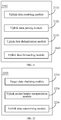
- Step S410 Obtain target service data packets.
- the obtaining target service data packets may include: controlling a server according to a service configuration request, to obtain target service server information, setting a filtering policy according to the target service server information, and intercepting the target service data packets according to the filtering policy.
- control server is a cloud control server
- target service server is a game server
- target service data packet is a game data packet
- Step S420 Separately encapsulate uplink packet headers for the target service data packets, to form a plurality of uplink data packets.
- Each uplink packet header may include a packet sequence number of each uplink data packet.
- Step S430 Transmit the plurality of uplink data packets to a proxy server in parallel through a plurality of channels.
- the method may further include: receiving, in parallel through the plurality of channels, a plurality of downlink data packets generated in response to the target service data packets, parsing the plurality of downlink data packets to obtain a plurality of response data packets and a plurality of downlink packet headers, and performing deduplication processing on the plurality of response data packets according to the plurality of downlink packet headers.
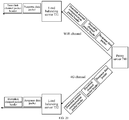
- FIG. 5 is a schematic diagram of a multichannel data transmission system according to an embodiment of this application.
- the multichannel data transmission system 500 may include a service client 510 and a proxy server 520.
- Parallel data transmission may be performed between the service client 510 and the proxy server 520 through a plurality of channels such as a channel 1, a channel 2, to a channel n (n is a positive integer greater than or equal to 2).
- the service client 510 may be configured to obtain target service data packets, separately encapsulate uplink packet headers for the target service data packets, to form a plurality of uplink data packets, and transmit the plurality of uplink data packets.
- the proxy server 520 may be configured to receive the plurality of uplink data packets in parallel through a plurality of channels, parse the plurality of uplink data packets to obtain a plurality of target service data packets and a plurality of uplink packet headers, perform deduplication processing on the plurality of target service data packets according to the plurality of uplink packet headers, and transmit the target service data packets reserved after the deduplication processing to a target service server 530.
- the proxy server 520 may be further configured to receive response data packets generated by the target service server 530 in response to the target service data packets, separately encapsulate corresponding downlink packet headers for the response data packets according to latest channel information of channel types, to generate a plurality of downlink data packets, and transmit the plurality of downlink data packets
- the service client 510 may be further configured to receive the plurality of downlink data packets in parallel through the plurality of channels, parse the plurality of downlink data packets to obtain a plurality of response data packets and a plurality of downlink packet headers, and perform deduplication processing on the plurality of response data packets according to the plurality of downlink packet headers.
- FIG. 6 is a schematic diagram of a multichannel data transmission system according to another embodiment of this application.
- the multichannel data transmission system 600 may include a service client 610, a load balancing server 620, and a proxy server 630.
- a service client 610 and the proxy server 630 reference may be made to the service client 510 and the proxy server 520 in the embodiment of FIG. 5 . Details are not described herein again.
- the multichannel data transmission system 600 provided in the implementation of this application may further include the load balancing server 620.
- the load balancing server 620 may be configured to receive the plurality of uplink data packets in parallel through the plurality of channels, determine a proxy server of the plurality of uplink data packets according to the uplink packet headers, and transmit the plurality of uplink data packets to the proxy server 630 in parallel through the plurality of channels.
- the method may further include that: after performing deduplication processing on the plurality of uplink data packets, the proxy server 630 sends deduplicated target service data packets to a target service server 640.
- the proxy server 630 may process response data packets returned by the target service server 640 in response to received target service data packets, to generate a plurality of downlink data packets and send the plurality of downlink data packets to the load balancing server 620 in parallel through the channel 1 to channel n, and the load balancing server 620 sends the plurality of downlink data packets to the service client 610 in parallel through the channel 1 to channel n.
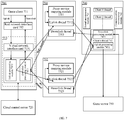
- FIG. 7 is a schematic overall architectural diagram of a multichannel data transmission method according to an embodiment of this application.
- a data transmission channel between a mobile phone client and a proxy server is established by using two channels of WiFi and 4G is used.
- three or more channels may be implemented.
- a dual-channel technology architecture provides a method for sending packets simultaneously based on two channels of a WiFi network and a 4G network.
- the method provided in this embodiment of this application may be applied to two access manners of a client software development kit (SDK) or a client application (APP).
- SDK software development kit
- APP client application
- a client APP 713 in FIG. 7 is used as an example for description, the same game data packet is sent to a proxy server 740 through two channels of WiFi and 4G for aggregation and deduplication, and then the deduplicated game data packet is sent to a game server 750.
- the proxy server 740 When receiving a response data packet of the game server 750, the proxy server 740 separately sends the response data packet through the WiFi channel and the 4G channel established with a client 710, thereby ensuring transmission stability of the game data packet and accessing a service for free cost.
- Logic of a dual-channel client may include the following steps.
- a game client 711 and the client APP 713 are started on the client 710 (for example, a mobile phone client, but is not limited thereto, which may be a terminal device of any type).
- the client APP 713 creates a virtual network interface card 7131 and establishes two threads for binding the WiFi channel and the 4G channel.
- the client APP 713 may send a request to a cloud control server 720 according to a corresponding game service configuration, and the cloud control server 720 delivers a game server IP to the client APP 713 according to the request.
- the client APP 713 sets a filtering policy iptables according to the game server IP, intercepts a game data packet of the game client 711 from a real network interface card 712, and forwards the game data packet to the virtual network interface card 7131.
- the mobile phone client may further have a plurality of other service data packets that are not game data packets
- only the configured game data packets may be sent through two channels, and other service data packets that are not the game data packets may be still received and sent by using a single channel, thereby reducing occupied network traffic.
- which game server or game data packets needs/need to be received and sent through two channels may be pre-configured and stored in the cloud control server 720, and the client APP 713 only intercepts a game data packet that needs to be sent through two channels and forwards the game data packet to the virtual network interface card 7131.
- the client APP 713 after receiving the game data packet from the virtual network interface card 7131, the client APP 713 encapsulates an uplink channel packet header by using an uplink processing module 7132, to form two uplink data packets, and separately sends the two uplink data packets to a load balancing server 731 and a load balancing server 732 through the WiFi channel and the 4G channel.
- the encapsulated uplink channel packet header may include the following information.
- the WiFi channel is a primary channel by default, and if a channel number of the WiFi channel is marked as 0, a primary channel identifier is 0.
- the channel identifier of 0 indicates that a channel type of a current uplink data packet is a WiFi channel
- the channel identifier of 1 indicates that a channel type of a current uplink data packet is a 4G channel.
- the unique identifier clientkey of the client may be obtained by using a hash32 algorithm.
- an operator ID mutisetID field of the primary channel is an operator identifier of the WiFi channel and may be used for determining a proxy server cluster.
- the client APP 713 may further receive, by using a downlink processing module 7133, a plurality of downlink data packets that are sent in parallel by the load balancing server 731 through the WiFi channel and the load balancing server 732 through the 4G channel, remove downlink packet headers in the downlink data packets by using the downlink processing module 7133, perform deduplication through deduplication logic, and send the downlink data packet after the deduplication to the game client 711 by using the virtual network interface card 7131 and the real network interface card 712 in sequence.
- the downlink packet header may include the following information.
- the load balancing server 731 may further include a proxy service mapping module 7311, an uplink thread 7312, and a downlink thread 7313
- the load balancing server 732 may further include a proxy service mapping module 7321, an uplink thread 7322, and a downlink thread 7323
- the proxy server 740 may further include a thread maintenance module 741, a communication maintenance module 742, a client 1 thread, a client 2 thread, to a client n thread. It is assumed that the client n thread 743 may further include a downlink processing module 7431 and an uplink processing module 7432.
- a downlink processing module 7431 For a specific implementation function, reference may be made to the following embodiments.
- the WiFi channel and the 4G channel are provided by different operators. Therefore, two load balancing server 731 and 732 are required. Similarly, if the method provided in this embodiment of this application is applied to three or more channels, the number of load balancing servers that are required is equal to the number of operators of the plurality of channels. Similarly, if the plurality of channels are provided by one operator, only one load balancing server may be required.
- proxy server cluster there may be a proxy server cluster.
- a plurality of uplink data packets that are sent by a client in parallel through a plurality of channels are sent to the same proxy server by using the load balancing server, and the load balancing server needs to determine the same proxy server (or referred to as a proxy serving node) in a proxy server cluster according to information in uplink packet headers in the uplink data packets.
- the proxy server cluster corresponding to a primary channel may be determined as a target cluster for determining the same proxy server according to the primary channel identifier in the uplink packet header.
- the same game data packet is sent simultaneously through two channels of WiFi and 4G, and as long as a game data packet on one of the network channels can arrive, user experience can still be normal, that is, disaster tolerance processing is performed on a client-server data receiving and sending network channel, to effectively prevent problems such as a packet loss and a high delay caused by WiFi or 4G network jitter.
- the proxy server may further shield a game client and a game server from a network change. The game client and the game server are unaware of a switching behavior among different network environments, and smooth switching can be achieved.
- real-time game stuck experience can be effectively improved.
- an optimization rate can be up to 90% for common WiFi interference.
- FIG. 8 is a schematic diagram of sending an uplink data packet by a client APP through a plurality of channels according to an embodiment of this application.
- the virtual network interface card 7131 in the client APP 713 sends a game data packet to the uplink processing module 7132, and the uplink processing module 7132 encapsulates an uplink packet header for the game data packet, to generate two uplink data packets, and separately sends the two uplink data packets through the WiFi channel and the 4G channel.
- FIG. 9 is a schematic diagram of receiving a downlink data packet by a client APP through a plurality of channels according to an embodiment of this application.
- the downlink processing module 7133 in the client APP 713 performs deduplication processing on a downlink data packet according to a downlink packet header, and then sends a game data packet obtained after the downlink packet header in the downlink data packet is removed and after the deduplication processing to the virtual network interface card 7131, and the virtual network interface card 7131 forwards the game data packet to the real network interface card 712.
- FIG. 10 is a schematic flowchart of a data packet deduplication method according to an embodiment of this application. It is to be noted that two data packet deduplication methods provided in FIG. 10 to FIG. 12 may be applied to both a client and a proxy server end.
- the data packet deduplication method provided in this embodiment of this application may include the following steps.
- Step S1001. Receive a new packet.
- a client receives a new downlink data packet
- a proxy server receives a new uplink data packet
- Step S1002 Determine whether a packet sequence number curSeqno of the new packet is greater than a maximum received packet sequence number of a channel of the new packet. If the packet sequence number curSeqno of the new packet is greater than the maximum received packet sequence number of the channel of the new packet, step S1003 is performed, and if the packet sequence number curSeqno of the new packet is less than or equal to the maximum received packet sequence number of the channel of the new packet, step S1006 is performed.
- a channel type of the new packet may be determined according to a channel identifier in a packet header (an uplink packet header or a downlink packet header) of the new packet. For example, if the channel identifier of the new packet is 0, it may be learned that the new packet is sent through a WiFi channel. In this case, a maximum received packet sequence number of the WiFi channel corresponding to the new packet may be learned. If the packet sequence number curSeqno of the new packet is greater than the maximum received packet sequence number of the WiFi channel, it indicates that this is a newly received packet for the WiFi channel. If the packet sequence number curSeqno of the new packet is less than or equal to the maximum received packet sequence number of the WiFi channel, it indicates that this is a previously received packet for the WiFi channel.
- a maximum received packet sequence number of a channel refers to a maximum packet sequence number previously received by the corresponding channel.
- the maximum received packet sequence number of the channel is not necessarily equal to a maximum received packet sequence number of a client provided below.
- Step S1003. Update the maximum received packet sequence number of the channel of the new packet.
- the new packet is from the WiFi channel
- a packet sequence number of the new packet is 2
- a maximum received packet sequence number of the WiFi channel is 1, the maximum received packet sequence number of the WiFi channel is updated to 2.
- Step S1004 Determine whether channel information of the new packet is consistent with previously stored channel information of the channel of the new packet. If the channel information of the new packet is inconsistent with the previously stored channel information of the channel of the new packet, step S1006 is performed, and if the channel information of the new packet is consistent with the previously stored channel information of the channel of the new packet, step S1005 is performed.
- the new packet is a new packet that is never received before for the WiFi channel
- whether the channel information such as a channel address of the new packet is consistent with a previously stored channel address of the WiFi channel may be determined. If the channel information such as a channel address of the new packet is inconsistent with the previously stored channel address of the WiFi channel, the channel address of the WiFi channel is updated. In this way, it may be ensured that a latest channel address is stored, thereby maintaining correct connection between the client and the proxy server.
- Step S1005. Update the channel information of the channel of the new packet.
- step S1003 and step S1004 may be performed in parallel.
- Step S1006 Determine whether the packet sequence number curSeqno of the new packet is greater than a maximum received packet sequence number MaxSeqno of the client. If the packet sequence number curSeqno of the new packet is greater than the maximum received packet sequence number MaxSeqno of the client, step S1007 is performed.
- the maximum received packet sequence number MaxSeqno of the client refers to a reserved and forwarded maximum packet sequence number that is previously received by the WiFi channel and the 4G channel.
- curSeqno>MaxSeqno it indicates that the new packet is a new packet that is never received before, and in this case, the new packet is reserved.
- Step S1007. Place packet sequence numbers across between the packet sequence number curSeqno of the new packet and the maximum received packet sequence number MaxSeqno of the client into an unreceived packet set.
- Step S1008 Determine whether a size of the unreceived packet set is greater than a first threshold recvThred. If size>recvThred, step S1009 is performed, and if size ⁇ recvThred, step S1011 is performed.
- the first threshold may be set to 10, but this application is not limited thereto.
- Step S1009 Delete several minimum unreceived packet sequence numbers from the unreceived packet set.
- the objective of the step is to limit the size of the unreceived packet set and maintain a quantity of packet sequence numbers in the unreceived packet set within the first threshold range.
- Step S1010 Update the maximum received packet sequence number MaxSeqno of the client.
- Step S10 Reserve and forward the packet.
- step S1009, step S1010, and step S1011 may not be performed according to a chronological order and may be performed in parallel.
- Step S1012 Determine whether a difference between the maximum received packet sequence number MaxSeqno of the client and the packet sequence number of the new packet is greater than the first threshold. If (MaxSeqno-curSeqno) ⁇ recvThred, step S1013 is performed, and if (MaxSeqno-curSeqno)>recvThred, step S1015 is performed.
- the new packet is discarded.
- the packet sequence number of the new packet is 7
- the maximum received packet sequence number MaxSeqno of the client is 20,
- the first threshold is an adjustable value and aims to limit a duration of the proxy server or the client waiting for a packet. In this case, a specific quantity of lost packets may be accepted. If a response level is high, the first threshold may be set smaller, for example, 10, and if the response level is low, the first threshold may be set larger, for example, 100. Even, the first threshold may be alternatively set to a maximum value in all packet sequence numbers, and this case means waiting indefinitely without packet loss.
- Step S1013. Determine whether the packet sequence number curSeqno of the new packet is in the unreceived packet set. If the packet sequence number curSeqno of the new packet is in the unreceived packet set, step S1014 is performed, and if the packet sequence number curSeqno of the new packet is not in the unreceived packet set, step S1015 is performed.
- Step S1014 Delete the packet sequence number curSeqno of the new packet from the unreceived packet set, perform step S1011, and reserve the new packet and forward the new packet.
- Step S1015 Discard the new packet.
- the method may further include: updating a quantity of first arrived packets of each channel and a quantity of arrived packets of each channel, which may be used for counting a data transmission effect of each channel.
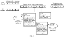
- FIG. 11 is a schematic diagram of an example based on the data packet deduplication method shown in FIG. 10 .
- packet sequence numbers of sequences sent by a client on a WiFi channel are 1, 2, 3, and 4 in sequence
- packet sequence numbers of sequences sent by a client on a 4G channel are also 1, 2, 3, and 4 in sequence
- packet sequence numbers of sequences received by a proxy server are 1 of the WiFi channel, 1 of the 4G channel, 4 of the WiFi channel, 2 of the 4G channel, 2 and 3 of the WiFi channel, and 3 and 4 of the 4G channel in sequence.
- the proxy server receives a packet of the 4G channel with a packet sequence number of 1.
- the proxy server receives a packet of the WiFi channel with a packet sequence number of 4.
- the proxy server receives a packet of the 4G channel with a packet sequence number of 2.
- packet sequence numbers of sequences forwarded by the proxy server are 1 of the WiFi channel, 4 of the WiFi channel, 2 of the 4G channel, and 3 of the WiFi channel in sequence.
- FIG. 12 is a schematic flowchart of a data packet deduplication method according to another embodiment of this application.
- the data packet deduplication method provided in this embodiment of this application may include the following steps.
- Step S1201. Receive a new packet.
- Step S1202. Determine whether a sequence number queue is empty. If the sequence number queue is empty, step S1208 is performed, and if the sequence number queue is not empty, step S1203 is performed.
- a sequence number queue corresponding to the client is empty, a packet sequence number of the new packet and a time stamp at this time are added to the sequence number queue, and the packet is reserved and forwarded.
- Step S1203. Traverse the sequence number queue in a forward direction.
- Step S1204. Delete an expired packet sequence number from the sequence number queue.
- the sequence number queue is traversed in the forward direction, a packet sequence number in which a time difference between an adding time and a current time exceeds a second threshold (for example, 500ms) in the sequence number queue is determined, and the packet sequence number and a time stamp of the packet sequence number are removed from the sequence number queue.
- a second threshold for example, 500ms
- the second threshold is also an adjustable value, and specifically, a duration limit for maintaining the sequence number queue is considered, to avoid excessive packet sequence numbers in the queue. This may result in that, for example, a packet sequence number received before 500ms is removed from the sequence number queue, and the same packet sequence number is re-received after 500ms, that is, a packet may be received repeatedly, but no packet is lost.
- Step S1205. Traverse the sequence number queue in a reverse direction.
- Step S1206 Determine whether a packet sequence number of the new packet is in the sequence number queue. If the packet sequence number of the new packet is in the sequence number queue, step S1207 is performed.
- Step S1207. Discard the new packet.
- Step S1208 Add the packet sequence number of the new packet and a timestamp at this time into the sequence number queue.
- Step S1209. Reserve and forward the new packet.
- deduplication logic is not limited to the two methods listed above, and the packet may be deduplicated by using any proper deduplication method according to an actual situation.
- FIG. 13 is a schematic diagram of a load balancing server according to an embodiment of this application.
- FIG. 13 is load balancing server logic in a dual-channel server end.
- a load balancing server 731 is used as an example for description.
- a client APP sends an uplink data packet of a WiFi channel or a 4G channel to a corresponding operator access point.
- the load balancing server 731 receives the uplink data packet through the WiFi channel.
- the uplink data packet includes an uplink channel packet header and a game data packet.
- the load balancing server 731 parses the uplink channel packet header to obtain a clientkey value and an operator ID of a primary channel corresponding to a mutisetID field in the packet header, so that it may be learned that the received uplink data packet is sent to which proxy server in a proxy server cluster in an operator.
- a proxy service mapping module 7311 in the load balancing server 731 may calculate a proxy serving node according to the clientkey value.
- an uplink thread 7312 in the load balancing server 731 further encapsulates an uplink internal communication packet header for the received uplink data packet, to form the uplink data packet including the uplink internal communication packet header, the uplink channel packet header, and the game data packet, and forwards the uplink data packet to the calculated proxy server 740.
- the uplink internal communication packet header may store client address information. For example:
- FIG. 14 is a schematic logical sequence diagram of an internal interaction between a load balancing server and a proxy server according to an embodiment of this application.
- step S1 A client sends an uplink data packet to a load balancing server through each channel, specifically to an uplink thread monitoring port 19000 of the load balancing server (this is an example for description and this application is not limited thereto).
- Step S2 A proxy service mapping module in the load balancing server and a redis communicate with each other, to obtain latest proxy serving node information, and meanwhile, the proxy service mapping module calculates, according to a clientkey in an uplink channel packet header of a received uplink data packet, a client exclusive proxy serving node to which the currently received uplink data packet is to be sent.
- the redis may be considered as a database.
- the proxy server in the proxy server cluster may change, for example, a new proxy server is added, an old proxy server is deleted, or an original proxy server is replaced. Therefore, to ensure that the proxy service mapping module can obtain an accurate exclusive proxy serving node through calculation, latest proxy server information needs to be stored in the redis, and then in calculating the proxy serving node to which a current packet is to be forwarded, the proxy service mapping module of the load balancing server reads the latest proxy server information in the redis for calculation.
- a storage device configured to store the proxy server information is not limited to the redis, and may be another storage device of any type.
- Step S3 The load balancing server continues to encapsulate an uplink internal communication packet header based on the received uplink data packet, and forwards the uplink data packet after the encapsulation to the exclusive proxy serving node found in step S2.
- Step S4 Create a client exclusive thread by using a main thread of the proxy server, remove the uplink internal communication packet header and the uplink channel packet header of the uplink data packet by using the client exclusive thread, and send a game data packet in the deduplicated uplink data packet to a game server.
- the proxy server starts an exclusive thread for each client, for listening to whether a new packet is sent to each client and a game server.
- Step S5 The proxy server receives, by using the client exclusive thread, a response data packet returned by the game server in response to the received game data packet.
- Step S6 The proxy server encapsulates a downlink internal communication packet header and a downlink channel packet header for the response data packet to form a downlink data packet, and sends the downlink data packet to each channel to the load balancing server.
- Step S7 The load balancing server sends the downlink data packet to each channel to the client through a port 19001.
- FIG. 15 is a schematic diagram of a proxy service mapping module of a load balancing server according to an embodiment of this application.
- the proxy service mapping module divides the proxy servers into several clusters according to operators, for example, four clusters: China Telecoms, China Mobile, China Unicom, and small and medium bandwidth operators.
- the proxy service mapping module evenly allocates N (N is an integer greater than or equal to 0) proxy serving nodes in each cluster to a range of 0 to 4294967295 (the value is only used as an example for description and this application is not limited thereto).
- a corresponding proxy serving node is calculated by using a clientkey value.
- the calculation formula may be as follows:
- the index is a proxy node number that is obtained through calculation, and each node number represents an address of a proxy server.
- each client has one exclusive thread, that is, after the same transmission channel is established, clientkey values of a plurality of uplink data packets sent by a WiFi channel and a 4G channel are all the same. After the current transmission channel is disconnected, the clientkey values are changed after the same client reestablishes the transmission channel.
- the proxy server may be expanded as received and sent data packets increase, and the proxy service mapping module accesses a redis cluster every a preset time such as every second and obtains a latest proxy server list. If the latest proxy server list is inconsistent with a latest proxy server node, an operation of adding, deleting, or replacing is implemented.
- FIG. 16 is a schematic diagram of a proxy service mapping module of a load balancing server according to another embodiment of this application.
- FIG. 16 is an example of node update logic for description. It is assumed that a node 4 is added behind the node 3. According to the foregoing formula for calculating the index, because svrInterval is at an equal interval, a virtual node needs to be added behind each original node. For example, virtual nodes 0, 1, and 2 are added to maintain consistency of the node calculation formula. Proxy server address information represented by a virtual node and proxy server address information represented by a previous node of the virtual node are the same. In this case, a quantity of nodes svrNum is doubled. For example, svrNum is equal to 8.
- a new node may be added at any location, and is not limited to be added behind the node 3.
- FIG. 17 is a schematic diagram of a proxy service mapping module of a load balancing server according to still another embodiment of this application.
- FIG. 17 is an example of deleting a proxy serving node. Assuming that the node 3 is deleted, a virtual node 2 needs to be added to complement the deleted location. Similarly, to maintain an equal interval feature, address information of the virtual node is the same as that of the previous node.
- FIG. 18 is a schematic diagram of a proxy service mapping module of a load balancing server according to yet another embodiment of this application.
- FIG. 18 is an example of replacing a proxy serving node. Assuming that the old node 3 is replaced, the node 3 may be replaced with information of a new node 4. For example, performance of a proxy server is degraded, and the proxy server is replaced by a new proxy server.
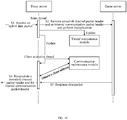
- FIG. 19 is a schematic logical sequence diagram of a proxy server according to an embodiment of this application.
- step S1. A proxy server receives an uplink data packet.
- Step S2 The proxy server removes an uplink channel packet header and an uplink internal communication packet header of the uplink data packet, deduplicates the uplink data packet, and then sends a game data packet to a game server.
- the proxy server updates a thread maintenance module, so that a client creates an exclusive thread at the proxy server for service and updates information in the thread maintenance module.
- the proxy server when newly receiving an uplink data packet sent by a client, the proxy server removes an uplink channel packet header and an uplink internal communication packet header of the uplink data packet to obtain client address information, and records the client address information in a communication maintenance module.
- the thread maintenance module may copy a piece of corresponding client address information from the communication maintenance module, and encapsulate the corresponding client address information in a downlink internal communication packet header, so that the proxy server may learn which client a downlink data packet is to be forwarded to.
- the client sends channel information of an uplink data packet to the proxy server in real time, to help the proxy server to perform channel switching, thereby ensuring that when abnormal switching of a 4G or WiFi channel occurs, the proxy server may instantly update channel information corresponding to the client.
- the channel information maintains channel packet header ver and type fields.
- the channel switching mainly refers to internal switching of 4G or internal switching of WiFi. Because a 4G address and a WiFi address may be changed, a connection between the client and the proxy server may be maintained according to the latest channel information in this embodiment of this application.
- WiFi is a primary channel. If WiFi is abnormal and cannot be networked, 4G may be switched to be the primary channel, and the channel packet header ver field is accordingly changed. In this case, a downlink data packet may be sent to the client only through the 4G channel. However, in this case, an operation such as encapsulating a downlink packet header may still be implemented by using a proxy server in a proxy server cluster of an operator corresponding to WiFi, without switching to a proxy server cluster of a 4G operator.
- the proxy server may identify, according to a unique identifier clientkey value of a client in an uplink channel packet header in an uplink data packet, client data sent from a 4G channel and a WiFi channel and perform deduplication processing on the client data.
- clientkey value For a deduplication algorithm, reference may be made to the foregoing embodiments in FIG. 10 to FIG. 12 .
- the proxy server establishes a unique link for a client and a game server, and sends a deduplicated game data packet to the game server.
- Step S3 The game server returns a response data packet in response to the game data packet.
- Step S4 The proxy server obtains a client address from a communication maintenance module, encapsulates the client address into a downlink internal communication packet header of the response data packet, encapsulates a downlink channel packet header for the response data packet, and then forwards the encapsulated response data packet.
- a client thread created by the proxy server listens to a dedicated link established by the client thread and the game server. After a response data packet returned by the game server is received, a downlink channel packet header and a downlink internal communication packet header are encapsulated according to latest address information of a WiFi channel and a 4G channel in the communication maintenance module, and the formed two downlink data packets are separately sent to the two channels.
- the proxy server may further clear client channel information regularly. For example, if no client data passes through the proxy server within a timeout time, threads and the channel information data of the client are cleared.
- FIG. 20 is a schematic diagram of sending a downlink data packet by a proxy server through a plurality of channels according to an embodiment of this application.
- a proxy server 740 respectively sends, through a WiFi channel and a 4G channel, a response data packet encapsulated with a downlink internal communication packet header and a downlink channel packet header, that is, a downlink data packet, to a load balancing server 731 and a load balancing server 732.
- the load balancing server 731 After removing the downlink internal communication packet header of the downlink data packet, the load balancing server 731 sends the downlink data packet to a service client (not shown in the figure) through the WiFi channel.
- the load balancing server 732 After removing the downlink internal communication packet header of the downlink data packet, the load balancing server 732 sends the downlink data packet to the service client (not shown in the figure) through the 4G channel.
- a downlink thread of the load balancing server after receiving a downlink data packet sent by the proxy server, a downlink thread of the load balancing server removes a downlink internal communication packet header, obtains client address information, and forwards the downlink data packet including a downlink channel packet header and a response data packet to the service client.
- the dual-channel load balancing server is mainly used to send data packets of different operators of a WiFi channel and a 4G channel to the same dual-channel proxy server by using a proxy service mapping module.
- the number of operators is equal to the number of dual-channel proxy server clusters.
- only a dual-channel proxy server cluster of an operator corresponding to a primary channel (which is the WiFi channel by default) may be used. Even if an abnormal shutdown of the WiFi channel may subsequently occur, the primary channel is changed into the 4G channel by using ver and type fields. In this case, because acceleration and initialization have been completed, a downlink data packet is still sent by using the dual-channel proxy server cluster of the operator corresponding to the WiFi channel.
- a downlink packet may be sent only through a primary channel, but in this solution, the downlink packet is sent through two channels.
- the method provided in the implementation of this application is relatively flexible, and most services may be accessed for free without any change and adaption.
- a fault occurs in a WiFi or 4G upper-layer network
- a user is completely unaware, and 70% or more client stuck cases can be prevented.
- the effect is relatively significant especially in a case of a relatively complex WiFi network.
- FIG. 21 is a schematic block diagram of a multichannel data transmission apparatus according to an embodiment of this application.
- the multichannel data transmission apparatus 2100 may include an uplink data receiving module 2110, an uplink data parsing module 2120, an uplink data deduplication module 2130, and an uplink data forwarding module 2140.
- the uplink data receiving module 2110 is configured to receive a plurality of uplink data packets in parallel through a plurality of channels.
- the uplink data parsing module 2120 is configured to parse the plurality of uplink data packets to obtain a plurality of target service data packets and a plurality of uplink packet headers.
- the uplink data deduplication module 2130 is configured to perform deduplication processing on the plurality of target service data packets according to the plurality of uplink packet headers.
- the uplink data forwarding module 2140 is configured to transmit the target service data packets reserved after the deduplication processing to a target service server.
- Each uplink packet header may include a packet sequence number of each uplink data packet.
- the uplink data deduplication module 2130 may include: a first packet discarding unit, configured to discard a corresponding target service data packet in a case that (MaxSeqno-curSeqno)>recvThred, and discard a corresponding target service data packet in a case that (MaxSeqno-curSeqno) ⁇ recvThred and curSeqno is not in an unreceived packet set.
- a first packet discarding unit configured to discard a corresponding target service data packet in a case that (MaxSeqno-curSeqno)>recvThred, and discard a corresponding target service data packet in a case that (MaxSeqno-curSeqno) ⁇ recvThred and curSeqno is not in an unreceived packet set.
- the uplink data deduplication module 2130 may further include: a first packet reserving unit, configured to reserve a corresponding target service data packet in a case that curSeqno>MaxSeqno, and reserve a corresponding target service data packet in a case that (MaxSeqno-curSeqno) ⁇ recvThred and packet sequence number is in the unreceived packet set.
- curSeqno is a packet sequence number of the uplink data packet
- MaxSeqno is a maximum received packet sequence number of a client
- recvThred is a first threshold.
- the uplink data deduplication module 2130 may include: a second packet reserving unit, configured to add the packet sequence number of the uplink data packet to a sequence number queue in a case that the packet sequence number of the uplink data packet is different from all packet sequence numbers in the sequence number queue, and reserve a corresponding target service data packet; and a second packet discarding unit, configured to discard a corresponding target service data packet in a case that the packet sequence number of the uplink data packet is the same as any packet sequence number in the sequence number queue.
- each uplink packet header further includes a channel identifier and channel information of each uplink data packet.
- the multichannel data transmission apparatus 2100 may further include: a channel type determining module, configured to determine a channel type of the uplink data packet according to the channel identifier, and a channel information updating module, configured to update channel information of a corresponding channel type in a case that the packet sequence number of the uplink data packet is greater than a maximum received packet sequence number of a channel of the corresponding channel type and corresponding channel information is inconsistent with channel information stored in the corresponding channel type.
- a channel type determining module configured to determine a channel type of the uplink data packet according to the channel identifier
- a channel information updating module configured to update channel information of a corresponding channel type in a case that the packet sequence number of the uplink data packet is greater than a maximum received packet sequence number of a channel of the corresponding channel type and corresponding channel information is inconsistent with channel information stored in the corresponding channel type.
- the multichannel data transmission apparatus 2100 may further include: a response data receiving module, configured to receive response data packets generated by the target service server in response to the target service data packets, a downlink data generation module, configured to separately encapsulate corresponding downlink packet headers for the response data packets according to latest channel information of channel types, to generate a plurality of downlink data packets, and a downlink data transmission module, configured to transmit the plurality of downlink data packets to a service client in parallel through the plurality of channels.
- a response data receiving module configured to receive response data packets generated by the target service server in response to the target service data packets
- a downlink data generation module configured to separately encapsulate corresponding downlink packet headers for the response data packets according to latest channel information of channel types, to generate a plurality of downlink data packets
- a downlink data transmission module configured to transmit the plurality of downlink data packets to a service client in parallel through the plurality of channels.
- FIG. 22 is a schematic block diagram of a multichannel data transmission apparatus according to another embodiment of this application.
- the multichannel data transmission apparatus 2200 may include a target data obtaining module 2210, an uplink packet header encapsulation module 2220, and an uplink data transmission module 2230.
- the target data obtaining module 2210 is configured to obtain target service data packets.
- the uplink packet header encapsulation module 2220 is configured to separately encapsulate uplink packet headers for the target service data packets, to form a plurality of uplink data packets.
- the uplink data transmission module 2230 is configured to transmit the plurality of uplink data packets to a proxy server in parallel through a plurality of channels.
- Each uplink packet header may include a packet sequence number of each uplink data packet.
- the multichannel data transmission apparatus 2200 may further include: a downlink data receiving module, configured to receive, in parallel through the plurality of channels, a plurality of downlink data packets generated in response to the target service data packets, a downlink data parsing module, configured to parse the plurality of downlink data packets to obtain a plurality of response data packets and a plurality of downlink packet headers, and a downlink data deduplication module, configured to perform deduplication processing on the plurality of response data packets according to the plurality of downlink packet headers.
- a downlink data receiving module configured to receive, in parallel through the plurality of channels, a plurality of downlink data packets generated in response to the target service data packets
- a downlink data parsing module configured to parse the plurality of downlink data packets to obtain a plurality of response data packets and a plurality of downlink packet headers
- a downlink data deduplication module configured to perform deduplication processing on the plurality of response data
- the target data obtaining module 2210 includes: a service server information obtaining unit, configured to control a server according to a service configuration request, to obtain target service server information, a filtering policy setting unit, configured to set a filtering policy according to the target service server information, and a target service data interception unit, configured to intercept the target service data packets according to the filtering policy.
- the software product may be stored in a non-volatile storage medium (which may be a CD-ROM, a USB flash drive, a removable hard disk, or the like) or on a network, and includes several instructions for instructing a computing device (which may be a personal computer, a server, a touch terminal, network device, or the like) to perform the methods according to the implementations of this application.
- a non-volatile storage medium which may be a CD-ROM, a USB flash drive, a removable hard disk, or the like
- a computing device which may be a personal computer, a server, a touch terminal, network device, or the like
Landscapes
- Engineering & Computer Science (AREA)
- Computer Networks & Wireless Communication (AREA)
- Signal Processing (AREA)
- Computer Security & Cryptography (AREA)
- Mobile Radio Communication Systems (AREA)
- Data Exchanges In Wide-Area Networks (AREA)
- Communication Control (AREA)
Abstract
Description
- The application claims priority to China Patent Application No.
2018109310957 - This application relates to the field of computer technologies, and in particular, to a data transmission technology.
- Currently, data transmission is generally implemented through a wireless fidelity (WiFi) channel or a cellular network. The cellular network may include a global system for mobile communication (GSM) network, a code division multiple access (CDMA) network, a frequency division multiple access (FDMA) network, a time division multiple access (TDMA) network, and a 3G/4G/5G channel. The 3rd generation partnership project (3GPP) aims at implementing smooth transition from a 2G network to a 3G/4G/5G network, to ensure backward compatibility of a future technology and support easy networking and roaming and compatibility between systems. The data transmission under a WiFi channel has an advantage of a low delay, but the WiFi channel is unstable, and phenomena such as channel interference, co-frequency interference, and worse signal strength are easily caused, resulting in a high delay from a terminal to a WiFi hotspot or a packet loss. Although being relatively stable, the cellular network (for example, 4G) has a higher delay than WiFi.
- That is, in the related art, whichever network is selected by a terminal for transmitting data, user experience may be affected. Especially during transmission of game data, the impact is more obvious. This is because a similar application such as a real-time mobile game faces frequent communication between a client and a server end, and a high-frequency small packet is mainly used. This type of application has a high requirement on a network environment, and has a strong requirement on a low delay and high stability. In addition, channel contention exists in the principle of the carrier sense multiple access/collision avoidance (CSMA/CA) mechanism of WiFi, the WiFi channels overlap or interfere with each other at the same frequency, and a signal is poor, all of above will cause a service packet loss or an increased delay.
- In the related art, to improve a data transmission effect of a game, there is a preferred single-channel packet sending solution that supports WiFi and 4G channels, that is, when a WiFi signal is worse, the 4G channel is used to send a packet. However, the single-channel packet sending solution has at least the following disadvantages:
- First, an operation of switching to 4G channel transmission is started only when a WiFi network has been worse, and the operation belongs to a post-remedial measure. In this case, user experience has been damaged.
- Second, it is difficult for a user to adapt to network switching of a game client caused by an operation such as switching of a network environment. This may bring severe stuck experience to the user.
- Third, during network jitter, data can only be switched from a path of a relatively bad network to a path of a relatively good network. For example, when WiFi is worse, some data packets are sent through a 4G channel, and when WiFi or 4G network jitter occurs, a data packet loss and a high delay situation cannot be avoided.
- In conclusion, a new data transmission method is currently required to ensure stable data transmission.
- It is to be noted that information disclosed in the background section is only used for enhancing the understanding of the background of this application, and therefore, may include information that does not constitute the related art known to a person of ordinary skill in the art.
- Embodiments of this application are intended to provide a multichannel data transmission method and apparatus, a computer-readable medium, and an electronic device, to resolve problems such as a stuck network, a packet loss, and a high delay in a data transmission process in the related art.
- Other features and advantages of this application become obvious through the following detailed descriptions, or may be learned partially by the practice of this application.
- According to an aspect of this application, a multichannel data transmission method is provided and applied to a proxy server, including: receiving a plurality of uplink data packets in parallel through a plurality of channels, parsing the plurality of uplink data packets to obtain a plurality of target service data packets and a plurality of uplink packet headers, performing deduplication processing on the plurality of target service data packets according to the plurality of uplink packet headers, and transmitting the target service data packets reserved after the deduplication processing to a target service server, each uplink packet header including a packet sequence number of each uplink data packet.
- In an exemplary embodiment of this application, the performing deduplication processing on the plurality of target service data packets according to the plurality of uplink packet headers includes: discarding a corresponding target service data packet in a case that (MaxSeqno-curSeqno)>recvThred, and discarding a corresponding target service data packet in a case that (MaxSeqno-curSeqno)≤recvThred and curSeqno is not in an unreceived packet set; reserving a corresponding service data packet in a case that curSeqno>MaxSeqno, and reserving a corresponding target service data packet in a case that (MaxSeqno-curSeqno)≤recvThred and curSeqno is in the unreceived packet set, curSeqno being a packet sequence number of the uplink data packet, MaxSeqno being a maximum received packet sequence number of a client, and recvThred being a first threshold.
- In an exemplary embodiment of this application, the performing deduplication processing on the plurality of target service data packets according to the plurality of uplink packet headers includes: adding the packet sequence number of the uplink data packet to a sequence number queue in a case that the packet sequence number of the uplink data packet is different from all packet sequence numbers in the sequence number queue, and reserving a corresponding target service data packet; and discarding a corresponding target service data packet in a case that the packet sequence number of the uplink data packet is the same as any of packet sequence numbers in the sequence number queue.
- In an exemplary embodiment of this application, each uplink packet header further includes a channel identifier and channel information of each uplink data packet, and the method further includes: determining a channel type of the uplink data packet according to the channel identifier, and updating channel information of a corresponding channel type in a case that the packet sequence number of the uplink data packet is greater than a maximum received packet sequence number of a channel of the corresponding channel type and corresponding channel information is inconsistent with channel information stored in the corresponding channel type.
- In an exemplary embodiment of this application, the method further includes: receiving response data packets generated by the target service server in response to the target service data packets, separately encapsulating corresponding downlink packet headers for the response data packets according to latest channel information of channel types, to generate a plurality of downlink data packets, and transmitting the plurality of downlink data packets to a service client in parallel through the plurality of channels.
- According to an aspect of this application, a multichannel data transmission method is provided and applied to a service client, including: obtaining target service data packets, separately encapsulating uplink packet headers for the target service data packets, to form a plurality of uplink data packets, and transmitting the plurality of uplink data packets to a proxy server in parallel through a plurality of channels, each uplink packet header including a packet sequence number of each uplink data packet.
- In an exemplary embodiment of this application, the method further includes: receiving, in parallel through the plurality of channels, a plurality of downlink data packets generated in response to the target service data packets, parsing the plurality of downlink data packets to obtain a plurality of response data packets and a plurality of downlink packet headers, and performing deduplication processing on the plurality of response data packets according to the plurality of downlink packet headers.
- In an exemplary embodiment of this application, the obtaining target service data packets includes: controlling a server according to a service configuration request, to obtain target service server information, setting a filtering policy according to the target service server information, and intercepting the target service data packets according to the filtering policy.
- According to an aspect of this application, a multichannel data transmission apparatus is provided, including: an uplink data receiving module, configured to receive a plurality of uplink data packets in parallel through a plurality of channels, an uplink data parsing module, configured to parse the plurality of uplink data packets to obtain a plurality of target service data packets and a plurality of uplink packet headers, an uplink data deduplication module, configured to perform deduplication processing on the plurality of target service data packets according to the plurality of uplink packet headers, and an uplink data forwarding module, configured to transmit the target service data packets reserved after the deduplication processing to a target service server, each uplink packet header including a packet sequence number of each uplink data packet.
- According to an aspect of this application, a multichannel data transmission apparatus is provided, including: a target data obtaining module, configured to obtain target service data packets, an uplink packet header encapsulation module, configured to separately encapsulate uplink packet headers for the target service data packets, to form a plurality of uplink data packets, and an uplink data transmission module, configured to transmit the plurality of uplink data packets to a proxy server in parallel through a plurality of channels, each uplink packet header including a packet sequence number of each uplink data packet.
- According to an aspect of this application, a multichannel data transmission system is provided, including: a service client, configured to obtain target service data packets, separately encapsulate uplink packet headers for the target service data packets, to form a plurality of uplink data packets, and transmit the plurality of uplink data packets, and a proxy server, configured to receive the plurality of uplink data packets in parallel through a plurality of channels, parse the plurality of uplink data packets to obtain a plurality of target service data packets and a plurality of uplink packet headers, perform deduplication processing on the plurality of target service data packets according to the plurality of uplink packet headers, and transmit the target service data packets reserved after the deduplication processing to a target service server.
- In an exemplary embodiment of this application, the proxy server is further configured to receive response data packets generated by the target service server in response to the target service data packets, separately encapsulate corresponding downlink packet headers for the response data packets according to latest channel information of channel types, to generate a plurality of downlink data packets, and transmit the plurality of downlink data packets; and the service client is further configured to receive the plurality of downlink data packets in parallel through the plurality of channels, parse the plurality of downlink data packets to obtain a plurality of response data packets and a plurality of downlink packet headers, and perform deduplication processing on the plurality of response data packets according to the plurality of downlink packet headers.
- In an exemplary embodiment of this application, the apparatus further includes: a load balancing server, configured to receive the plurality of uplink data packets in parallel through the plurality of channels, determine a proxy server of the plurality of uplink data packets according to uplink packet headers, and transmit the plurality of uplink data packets to the proxy server in parallel through the plurality of channels.
- According to an aspect of this application, a computer-readable medium is provided, storing a computer program, the program, when executed by a processor, implementing the method according to any one of the foregoing embodiments.
- According to an aspect of this application, an electronic device is provided, including: one or more processors, and a storage apparatus, configured to store one or more computer programs, the one or more computer programs, when executed by the one or more processors, causing the one or more processors to implement the method according to any one of the foregoing embodiments.
- In the technical solutions provided in some embodiments of this application, a plurality of uplink data packets are received in parallel through a plurality of channels, the plurality of uplink data packets are parsed to obtain a plurality of target service data packets and a plurality of uplink packet headers, then, deduplication processing is performed on the plurality of target service data packets according to the plurality of uplink packet headers, and next, the target service data packets reserved after the deduplication processing are transmitted to a target service server. Each uplink packet header includes a packet sequence number of each uplink data packet. On one hand, packets are received simultaneously through a plurality of channels, so that transmission stability and effectiveness of the target service data packets can be ensured. On the other hand, uplink data packets received in parallel are aggregated and deduplicated and then forwarded to a target service server, and the target service server is shielded from network changes, thereby ensuring that the target service server is unaware of changes of different network environments, and running of the target service server is not affected.
- It is to be understood that, the foregoing general descriptions and the following detailed descriptions are merely for illustration and explanation purposes and are not intended to limit this application.
- The accompanying drawings herein are included in the specification and form a part of the specification, show embodiments that conform to this application, and are used to describe a principle of this application together with the specification. Obviously, the accompanying drawings described below are only some embodiments of this application, and a person of ordinary skill in the art can obtain other accompanying drawings according to these accompanying drawings without creative efforts. In the drawings:
-
FIG. 1 is a schematic diagram of an exemplary system architecture to which a multichannel data transmission method or a multichannel data transmission apparatus according to embodiments of this application may be applied. -
FIG. 2 is a schematic structural diagram of a computer system of an electronic device adapted to embodiments of this application. -
FIG. 3 is a schematic flowchart of a multichannel data transmission method according to an embodiment of this application. -
FIG. 4 is a schematic flowchart of a multichannel data transmission method according to another embodiment of this application. -
FIG. 5 is a schematic diagram of a multichannel data transmission system according to an embodiment of this application. -
FIG. 6 is a schematic diagram of a multichannel data transmission system according to another embodiment of this application. -
FIG. 7 is a schematic overall architectural diagram of a multichannel data transmission method according to an embodiment of this application. -
FIG. 8 is a schematic diagram of sending an uplink data packet by a client APP through a plurality of channels according to an embodiment of this application. -
FIG. 9 is a schematic diagram of receiving a downlink data packet by a client APP through a plurality of channels according to an embodiment of this application. -
FIG. 10 is a schematic flowchart of a data packet deduplication method according to an embodiment of this application. -
FIG. 11 is a schematic diagram of an example based on the data packet deduplication method shown inFIG. 10 . -
FIG. 12 is a schematic flowchart of a data packet deduplication method according to another embodiment of this application. -
FIG. 13 is a schematic diagram of a load balancing server according to an embodiment of this application. -
FIG. 14 is a schematic logical sequence diagram of an internal interaction between a load balancing server and a proxy server according to an embodiment of this application. -
FIG. 15 is a schematic diagram of a proxy service mapping module of a load balancing server according to an embodiment of this application. -
FIG. 16 is a schematic diagram of a proxy service mapping module of a load balancing server according to another embodiment of this application. -
FIG. 17 is a schematic diagram of a proxy service mapping module of a load balancing server according to still another embodiment of this application. -
FIG. 18 is a schematic diagram of a proxy service mapping module of a load balancing server according to yet another embodiment of this application. -
FIG. 19 is a schematic logical sequence diagram of a proxy server according to an embodiment of this application. -
FIG. 20 is a schematic diagram of sending a downlink data packet by a proxy server through a plurality of channels according to an embodiment of this application. -
FIG. 21 is a schematic block diagram of a multichannel data transmission apparatus according to an embodiment of this application. -
FIG. 22 is a schematic block diagram of a multichannel data transmission apparatus according to another embodiment of this application. - At present, exemplary implementations are described comprehensively with reference to the accompanying drawings. However, the exemplary implementations may be implemented in multiple forms, and it is not to be understood as being limited to the examples described herein. Conversely, the implementations are provided to make this application more comprehensive and complete, and comprehensively convey the idea of the exemplary implementations to a person skilled in the art.
- In addition, the described characteristics, structures, or features may be combined in one or more embodiments in any appropriate manner. In the following descriptions, a lot of specific details are provided to give a comprehensive understanding of the embodiments of this application. However, a person of ordinary skill in the art is to be aware that, the technical solutions in this application may be implemented without one or more of the particular details, or another method, unit, apparatus, or step may be used. In other cases, well-known methods, apparatuses, implementations, or operations are not shown or described in detail, in order not to obscure the aspects of this application.
- The block diagrams shown in the accompany drawings are merely functional entities and do not necessarily correspond to physically independent entities. That is, such functional entities may be implemented in the form of software, or implemented in one or more hardware modules or integrated circuits, or implemented in different networks and/or processor apparatuses and/or microcontroller apparatuses.
- The flowcharts shown in the accompanying drawings are merely exemplary descriptions and do not necessarily include all of the content and operations/steps, nor are they necessarily performed in the sequence described. For example, some operations/steps may be further divided, and some operations/steps may be combined or partially combined. Therefore, an actual execution sequence may be changed according to an actual situation.
-
FIG. 1 is a schematic diagram of anexemplary system architecture 100 to which a multichannel data transmission method or a multichannel data transmission apparatus according to embodiments of this application may be applied. - As shown in
FIG. 1 , thesystem architecture 100 may include any one or more ofterminal devices network 104, and aserver 105. Thenetwork 104 is configured to provide a medium of a communication link between theterminal devices server 105. Thenetwork 104 may include various connection types, for example, a wired communication link, a wireless communication link, or a fiber optic cable. - It is to be understood that quantities of the terminal devices, the networks, and the servers in
FIG. 1 are merely exemplary. There may be any quantity of terminal devices, networks, and servers according to implementation requirements. For example, theserver 105 may be a server cluster formed by a plurality of servers. - A user may interact with the
server 105 by using theterminal devices network 104, to receive or send a message or the like. Theterminal devices - The
server 105 may be a server that provides a related service. For example, a user sends, by using the terminal device 103 (or theterminal device 101 or 102), a request for obtaining game-related information and/or resource to theserver 105, theserver 105 may correspondingly obtain the game-related information and/or resource based on the received information request of the game-related information and/or resource and feed back the game-related information and/or resource to theterminal device 103, and theterminal device 103 may further display the received game-related information and/or resource. The user sends, by using the terminal device 103 (or theterminal device 101 or 102), a game operation instruction to theserver 105 according to the game-related information and/or resource displayed on theterminal device 103, theserver 105 may correspondingly return an execution result of the game operation instruction to theterminal device 103 based on the received game operation instruction, and theterminal device 103 correspondingly displays the received execution result of the game operation instruction. -
FIG. 2 is a schematic structural diagram of an electronic device adapted to implement embodiments of this application. - It is to be noted that a
computer system 200 of the electronic device shown inFIG. 2 is merely an example, and does not constitute any limitation on functions and use ranges of embodiments of this application. - As shown in
FIG. 2 , thecomputer system 200 includes a central processing unit (CPU) 201, which may perform various proper actions and processing based on a program stored in a read-only memory (ROM) 202 or a program loaded from astorage part 208 into a random access memory (RAM) 203. TheRAM 203 further stores various programs and data required for system operation. TheCPU 201, theROM 202, and theRAM 203 are connected to each other by using abus 204. An input/output (I/O)interface 205 is also connected to thebus 204. - The following components are connected to the I/O interface 205: an
input part 206 including a keyboard, a mouse, or the like, anoutput part 207 including a cathode ray tube (CRT), a liquid crystal display (LCD), a speaker, or the like, astorage part 208 including a hard disk, or the like, and acommunication part 209 including a network interface card such as a LAN card or a modem. Thecommunication part 209 performs communication processing by using a network such as the Internet. Adriver 210 is also connected to the I/O interface 205 as required. Aremovable medium 211 such as a magnetic disk, an optical disc, a magneto-optical disk, or a semiconductor memory is installed on thedriver 210 as required, so that a computer program read from theremovable medium 211 is installed into thestorage part 208 as required. - Particularly, according to an embodiment of this application, the processes described below by referring to the flowcharts may be implemented as computer software programs. For example, an embodiment of this application includes a computer program product, which includes a computer program stored in a computer-readable medium. The computer program includes program code used for performing the methods shown in the flowcharts. In such an embodiment, by using the
communication part 209, the computer program may be downloaded and installed from a network, and/or installed from theremovable medium 211. When the computer program is executed by theCPU 201, the various functions defined in the method and/or apparatus of this application are executed. - It is to be noted that the computer-readable medium in this application may be a computer-readable signal medium or a computer-readable storage medium or any combination thereof. The computer-readable storage medium may be, but not limited to, an electric, magnetic, optical, electromagnetic, infrared, or semi-conductive system, apparatus, or device, or any combination thereof. A more specific example of the computer-readable storage medium may include but is not limited to: an electrical connection having one or more wires, a portable computer magnetic disk, a hard disk, a RAM, a ROM, an erasable programmable read-only memory (EPROM or flash memory), an optical fiber, a compact disk read-only memory (CD-ROM), an optical storage device, a magnetic storage device, or any appropriate combination thereof. In this application, the computer-readable storage medium may be any tangible medium including or storing a program, and the program may be used by or in combination with an instruction execution system, apparatus, or device. In this application, the computer-readable signal medium may include a data signal transmitted in a baseband or as part of a carrier, and stores computer-readable program code. The propagated data signal may be in a plurality of forms, including, but not limited to, an electromagnetic signal, an optical signal, or any appropriate combination thereof. The computer-readable signal medium may alternatively be any computer-readable medium other than the computer-readable storage medium. The computer-readable medium may be configured to send, propagate, or transmit a program configured to be used by or in combination with an instruction execution system, apparatus, or device. The program code included in the computer-readable medium may be transmitted by using any suitable medium, including but not limited to, wireless transmission, a wire, a cable, radio frequency (RF) or the like, or any suitable combination thereof.
- The flowcharts and block diagrams in the accompanying drawings show architectures, functions, and operations that may be implemented for the method, the apparatus, and the computer program product according to the embodiments of this application. In this regard, each box in a flowchart or a block diagram may represent a module, a program segment, or a part of code. The module, the program segment, or the part of code includes one or more executable instructions used for implementing specified logic functions. In some alternative implementations, functions annotated in boxes may occur in a sequence different from that annotated in the accompanying drawing. For example, actually two boxes shown in succession may be performed basically in parallel, and sometimes the two boxes may be performed in a reverse sequence. This is determined by a related function. Each box in a block diagram or a flowchart and a combination of boxes in the block diagram or the flowchart may be implemented by using a dedicated hardware-based system configured to perform a specified function or operation, or may be implemented by using a combination of dedicated hardware and a computer instruction.
- A related module and/or unit described in the embodiments of this application may be implemented in a software manner, or may be implemented in a hardware manner. The described module and/or unit may alternatively be disposed in a processor. Names of these modules and/or units do not constitute a limitation on the modules and/or units in some case.
- According to another aspect, this application further provides a computer-readable medium. The computer-readable medium may be included in the electronic device described in the foregoing embodiments, or may exist alone and is not assembled in the electronic device. The computer-readable medium stores one or more programs. The one or more programs, when executed by the electronic device, cause the electronic device to implement the methods according to the following embodiments. For example, the electronic device may implement steps in any of the embodiments shown in
FIG. 3 to FIG. 20 . -
FIG. 3 is a schematic flowchart of a multichannel data transmission method according to an embodiment of this application. - As shown in
FIG. 3 , the multichannel data transmission method provided in the implementation of this application may include the following steps. The method provided in the implementation of this application may be, for example, performed by a proxy server, but this application is not limited thereto. - Step S310. Receive a plurality of uplink data packets in parallel through a plurality of channels.
- In this embodiment of this application, a quantity and a type of channels are not limited, the quantity of channels may be determined according to a quantity of communication channels that can be supported between a client and the proxy server, for example, may include at least two of a WiFi channel, a 3G/4G/5G channel, a wired channel, and the like.
- In this embodiment of this application, each uplink data packet may include an uplink packet header and a target service data packet. The uplink packet header may further include an uplink internal communication packet header and an uplink channel packet header, and the uplink internal communication packet header may include a service client address for sending the uplink data packet to the proxy server.
- Step S320. Parse the plurality of uplink data packets to obtain a plurality of target service data packets and a plurality of uplink packet headers.
- In this embodiment of this application, an uplink packet header in each uplink data packet is removed from the uplink data packet, to obtain a target service data packet.
- Step S330. Perform deduplication processing on the plurality of target service data packets according to the plurality of uplink packet headers.
- Each uplink packet header includes a packet sequence number of each uplink data packet.
- In an exemplary embodiment, each uplink packet header may further include a channel identifier and channel information of each uplink data packet. The channel identifier is used for identifying a channel through which a current uplink data packet is sent. The channel information may include a channel address for sending the current uplink data packet, for example, an Internet Protocol (IP) address or a port of a WiFi channel.
- In an exemplary embodiment, the performing deduplication processing on the plurality of target service data packets according to the plurality of uplink packet headers may include: discarding a target service data packet in a case that (MaxSeqno-curSeqno)>recvThred, discarding a corresponding target service data packet in a case that (MaxSeqno-curSeqno)≤recvThred and curSeqno is not in an unreceived packet set, reserving a target service data packet in a case that curSeqno>MaxSeqno, and reserving a corresponding target service data packet in a case that (MaxSeqno-curSeqno)≤recvThred and the packet sequence number is in the unreceived packet set, curSeqno being a packet sequence number of the uplink data packet, MaxSeqno being a maximum received packet sequence number of a client, and recvThred being a first threshold.
- For example, assuming that the first threshold recvThred is 10, a current maximum received packet sequence number MaxSeqno of a client is 20 and a packet sequence number curSeqno of a currently received uplink data packet is 5, in this case, MaxSeqno-curSeqno=20-5=15>10, and the uplink data packet with the packet sequence number of 5 is discarded.
- In another example, assuming that the first threshold recvThred is 10, a current maximum received packet sequence number MaxSeqno of a client is 20 and a packet sequence number curSeqno of a currently received uplink data packet is 15, in this case, MaxSeqno-curSeqno=20-15=5<10, the unreceived packet set does not include the packet sequence number 15, and similarly the uplink data packet with the packet sequence number of 15 is discarded.
- In still another example, assuming that the first threshold recvThred is 10, a current maximum received packet sequence number MaxSeqno of a client is 20 and a packet sequence number curSeqno of a currently received uplink data packet is 15, in this case, MaxSeqno-curSeqno=20-15=5<10, the unreceived packet set includes the packet sequence number 15, and the uplink data packet with the packet sequence number of 15 is reserved, and the packet sequence number 15 is deleted from the unreceived packet set.
- In an exemplary embodiment, the performing deduplication processing on the plurality of target service data packets according to the plurality of uplink packet headers may include: adding the packet sequence number of the uplink data packet to a sequence number queue in a case that the packet sequence number of the uplink data packet is different from packet sequence numbers in the sequence number queue, and reserving a corresponding target service data packet; and discarding a corresponding target service data packet in a case that the packet sequence number of the uplink data packet is the same as any packet sequence number in the sequence number queue.
- In an exemplary embodiment, the method may further include: determining a channel type of the uplink data packet according to the channel identifier, and updating channel information of a corresponding channel type in a case that the packet sequence number of the uplink data packet is greater than a maximum received packet sequence number of a channel of the corresponding channel type and corresponding channel information is not consistent with channel information stored in the corresponding channel type.
- Step S340. Transmit the target service data packets reserved after the deduplication processing to a target service server.
- In an exemplary embodiment, the method may further include: receiving response data packets generated by the target service server in response to the target service data packets, separately encapsulating corresponding downlink packet headers for the response data packets according to latest channel information of channel types, to generate a plurality of downlink data packets, and transmitting the plurality of downlink data packets to a service client in parallel through the plurality of channels.
- In the multichannel data transmission method provided in the implementation of this application, a plurality of uplink data packets are received in parallel through a plurality of channels, the plurality of uplink data packets are parsed to obtain a plurality of target service data packets and a plurality of uplink packet headers, then deduplication processing is performed on the plurality of target service data packets according to the plurality of uplink packet headers, and next, the target service data packets reserved after the deduplication processing are transmitted to a target service server, each uplink packet header including a packet sequence number of each uplink data packet. On one hand, packets are received simultaneously through a plurality of channels, so that transmission stability and effectiveness of the target service data packets can be ensured. On the other hand, uplink data packets received in parallel are aggregated and deduplicated and then forwarded to a target service server, and the target service server is shielded from network changes, thereby the target service server is unaware of changes in different network environments, and running of the target service server is not affected.
-
FIG. 4 is a schematic flowchart of a multichannel data transmission method according to another embodiment of this application. The method provided in the implementation of this application may be, for example, performed by a service client, but this application is not limited thereto. - As shown in
FIG. 4 , the multichannel data transmission method provided in the implementation of this application may include the following steps. - Step S410. Obtain target service data packets.
- In an exemplary embodiment, the obtaining target service data packets may include: controlling a server according to a service configuration request, to obtain target service server information, setting a filtering policy according to the target service server information, and intercepting the target service data packets according to the filtering policy.
- In the following embodiments, descriptions are provided by using examples in which the control server is a cloud control server, the target service server is a game server, the target service data packet is a game data packet, but this application is not limited thereto and may be set according to a specific application scenario.
- Step S420. Separately encapsulate uplink packet headers for the target service data packets, to form a plurality of uplink data packets.
- Each uplink packet header may include a packet sequence number of each uplink data packet.
- Step S430. Transmit the plurality of uplink data packets to a proxy server in parallel through a plurality of channels.
- In an exemplary embodiment, the method may further include: receiving, in parallel through the plurality of channels, a plurality of downlink data packets generated in response to the target service data packets, parsing the plurality of downlink data packets to obtain a plurality of response data packets and a plurality of downlink packet headers, and performing deduplication processing on the plurality of response data packets according to the plurality of downlink packet headers.
-
FIG. 5 is a schematic diagram of a multichannel data transmission system according to an embodiment of this application. - As shown in
FIG. 5 , the multichanneldata transmission system 500 provided in the implementation of this application may include aservice client 510 and aproxy server 520. Parallel data transmission may be performed between theservice client 510 and theproxy server 520 through a plurality of channels such as achannel 1, achannel 2, to a channel n (n is a positive integer greater than or equal to 2). - The
service client 510 may be configured to obtain target service data packets, separately encapsulate uplink packet headers for the target service data packets, to form a plurality of uplink data packets, and transmit the plurality of uplink data packets. - The
proxy server 520 may be configured to receive the plurality of uplink data packets in parallel through a plurality of channels, parse the plurality of uplink data packets to obtain a plurality of target service data packets and a plurality of uplink packet headers, perform deduplication processing on the plurality of target service data packets according to the plurality of uplink packet headers, and transmit the target service data packets reserved after the deduplication processing to atarget service server 530. - In an exemplary embodiment, the
proxy server 520 may be further configured to receive response data packets generated by thetarget service server 530 in response to the target service data packets, separately encapsulate corresponding downlink packet headers for the response data packets according to latest channel information of channel types, to generate a plurality of downlink data packets, and transmit the plurality of downlink data packets, and theservice client 510 may be further configured to receive the plurality of downlink data packets in parallel through the plurality of channels, parse the plurality of downlink data packets to obtain a plurality of response data packets and a plurality of downlink packet headers, and perform deduplication processing on the plurality of response data packets according to the plurality of downlink packet headers. -
FIG. 6 is a schematic diagram of a multichannel data transmission system according to another embodiment of this application. - As shown in
FIG. 6 , the multichanneldata transmission system 600 provided in the implementation of this application may include aservice client 610, aload balancing server 620, and aproxy server 630. For theservice client 610 and theproxy server 630, reference may be made to theservice client 510 and theproxy server 520 in the embodiment ofFIG. 5 . Details are not described herein again. - A difference from the embodiment shown in
FIG. 5 lies in that the multichanneldata transmission system 600 provided in the implementation of this application may further include theload balancing server 620. Theload balancing server 620 may be configured to receive the plurality of uplink data packets in parallel through the plurality of channels, determine a proxy server of the plurality of uplink data packets according to the uplink packet headers, and transmit the plurality of uplink data packets to theproxy server 630 in parallel through the plurality of channels. - In this embodiment of this application, the method may further include that: after performing deduplication processing on the plurality of uplink data packets, the
proxy server 630 sends deduplicated target service data packets to atarget service server 640. Alternatively, theproxy server 630 may process response data packets returned by thetarget service server 640 in response to received target service data packets, to generate a plurality of downlink data packets and send the plurality of downlink data packets to theload balancing server 620 in parallel through thechannel 1 to channel n, and theload balancing server 620 sends the plurality of downlink data packets to theservice client 610 in parallel through thechannel 1 to channel n. - The following further describes the above method and system with reference to specific examples, which are not intended to limit this application.
-
FIG. 7 is a schematic overall architectural diagram of a multichannel data transmission method according to an embodiment of this application. Herein, an example in which a data transmission channel between a mobile phone client and a proxy server is established by using two channels of WiFi and 4G is used. However, actually, in the method provided in the embodiment of this application, three or more channels may be implemented. - As shown in
FIG. 7 , a dual-channel technology architecture provides a method for sending packets simultaneously based on two channels of a WiFi network and a 4G network. The method provided in this embodiment of this application may be applied to two access manners of a client software development kit (SDK) or a client application (APP). Aclient APP 713 inFIG. 7 is used as an example for description, the same game data packet is sent to aproxy server 740 through two channels of WiFi and 4G for aggregation and deduplication, and then the deduplicated game data packet is sent to agame server 750. When receiving a response data packet of thegame server 750, theproxy server 740 separately sends the response data packet through the WiFi channel and the 4G channel established with aclient 710, thereby ensuring transmission stability of the game data packet and accessing a service for free cost. - Logic of a dual-channel client may include the following steps.
- First, a
game client 711 and theclient APP 713 are started on the client 710 (for example, a mobile phone client, but is not limited thereto, which may be a terminal device of any type). After being started, theclient APP 713 creates a virtualnetwork interface card 7131 and establishes two threads for binding the WiFi channel and the 4G channel. - In this embodiment of this application, the
client APP 713 may send a request to acloud control server 720 according to a corresponding game service configuration, and thecloud control server 720 delivers a game server IP to theclient APP 713 according to the request. Theclient APP 713 sets a filtering policy iptables according to the game server IP, intercepts a game data packet of thegame client 711 from a realnetwork interface card 712, and forwards the game data packet to the virtualnetwork interface card 7131. Because the mobile phone client may further have a plurality of other service data packets that are not game data packets, in this embodiment of this application, only the configured game data packets may be sent through two channels, and other service data packets that are not the game data packets may be still received and sent by using a single channel, thereby reducing occupied network traffic. Further, which game server or game data packets needs/need to be received and sent through two channels may be pre-configured and stored in thecloud control server 720, and theclient APP 713 only intercepts a game data packet that needs to be sent through two channels and forwards the game data packet to the virtualnetwork interface card 7131. - In this embodiment of this application, after receiving the game data packet from the virtual
network interface card 7131, theclient APP 713 encapsulates an uplink channel packet header by using anuplink processing module 7132, to form two uplink data packets, and separately sends the two uplink data packets to aload balancing server 731 and aload balancing server 732 through the WiFi channel and the 4G channel. - In this embodiment of this application, the encapsulated uplink channel packet header may include the following information.

- The WiFi channel is a primary channel by default, and if a channel number of the WiFi channel is marked as 0, a primary channel identifier is 0. Correspondingly, the channel identifier of 0 indicates that a channel type of a current uplink data packet is a WiFi channel, and the channel identifier of 1 indicates that a channel type of a current uplink data packet is a 4G channel. The unique identifier clientkey of the client may be obtained by using a hash32 algorithm.
- In this embodiment of this application, if the WiFi channel and the 4G channel belong to different operators and the WiFi channel is a primary channel, an operator ID mutisetID field of the primary channel is an operator identifier of the WiFi channel and may be used for determining a proxy server cluster.
- In this embodiment of this application, the
client APP 713 may further receive, by using adownlink processing module 7133, a plurality of downlink data packets that are sent in parallel by theload balancing server 731 through the WiFi channel and theload balancing server 732 through the 4G channel, remove downlink packet headers in the downlink data packets by using thedownlink processing module 7133, perform deduplication through deduplication logic, and send the downlink data packet after the deduplication to thegame client 711 by using the virtualnetwork interface card 7131 and the realnetwork interface card 712 in sequence. - In this embodiment of this application, the downlink packet header may include the following information.
              typedef struct MutiTunnelDownHead{
                  uint32_t seqno; //packet sequence number
                  char data[0]; //packet content
              } MutiTunnelDownHead
              typedef struct InerPkg{
                  struct sockaddr_in clientInfo; //client address information
                  char data[0];
              } InerPkg;
- svrNum (a quantity of dual-channel proxy nodes) // assumed to be 4 herein
- MAX//maximum value, assumed to be 4294967295 herein
- svrInterval = MAX/svrNum//assumed to be 1073741823.75 herein;
- index = (clientkey/svrInterval)%svrNum;//% is a modulus operation
- 0≤clientkey<1073741823, falling on the
node 0; - 1073741823≤clientkey<2147483647, falling on the
node 1; - 2147483647≤clientkey<3221225471, falling on the
node 2; - 3221225471≤clientkey<4294967295, falling on the
node 3.
Claims (15)
- A multichannel data transmission method, applied to a proxy server, the method comprising:receiving a plurality of uplink data packets in parallel through a plurality of channels;parsing the plurality of uplink data packets to obtain a plurality of target service data packets and a plurality of uplink packet headers;performing deduplication processing on the plurality of target service data packets according to the plurality of uplink packet headers; andtransmitting the target service data packets reserved after the deduplication processing to a target service server,each uplink packet header comprising a packet sequence number of each uplink data packet.
- The method according to claim 1, wherein the performing deduplication processing on the plurality of target service data packets according to the plurality of uplink packet headers comprises:discarding a corresponding target service data packet in a case that (MaxSeqno-curSeqno)>recvThred, and discarding a corresponding target service data packet in a case that (MaxSeqno-curSeqno)≤recvThred and curSeqno is not in an unreceived packet set;reserving a corresponding target service data packet in a case that curSeqno>MaxSeqno; andreserving a corresponding target service data packet in a case that (MaxSeqno-curSeqno)≤recvThred and curSeqno is in the unreceived packet set,curSeqno being a packet sequence number of the uplink data packet, MaxSeqno being a maximum received packet sequence number of a client, and recvThred being a first threshold.
- The method according to claim 1, wherein the performing deduplication processing on the plurality of target service data packets according to the plurality of uplink packet headers comprises:adding the packet sequence number of the uplink data packet to a sequence number queue in a case that the packet sequence number of the uplink data packet is different from all packet sequence numbers in the sequence number queue, and reserving a corresponding target service data packet; anddiscarding a corresponding target service data packet in a case that the packet sequence number of the uplink data packet is the same as any packet sequence number in the sequence number queue.
- The method according to claim 1, wherein each uplink packet header further comprises a channel identifier and channel information of each uplink data packet, and the method further comprises:determining a channel type of the uplink data packet according to the channel identifier; andupdating channel information of a corresponding channel type in a case that the packet sequence number of the uplink data packet is greater than a maximum received packet sequence number of a channel of the corresponding channel type and corresponding channel information is inconsistent with channel information stored in the corresponding channel type.
- The method according to claim 4, further comprising:receiving response data packets generated by the target service server in response to the target service data packets;separately encapsulating corresponding downlink packet headers for the response data packets according to latest channel information of channel types, to generate a plurality of downlink data packets; andtransmitting the plurality of downlink data packets to a service client in parallel through the plurality of channels.
- A multichannel data transmission method, applied to a service client, the method comprising:obtaining target service data packets;separately encapsulating uplink packet headers for the target service data packets, to form a plurality of uplink data packets; andtransmitting the plurality of uplink data packets to a proxy server in parallel through a plurality of channels,each uplink packet header comprising a packet sequence number of each uplink data packet.
- The method according to claim 6, further comprising:receiving, in parallel through the plurality of channels, a plurality of downlink data packets generated in response to the target service data packets;parsing the plurality of downlink data packets to obtain a plurality of response data packets and a plurality of downlink packet headers; andperforming deduplication processing on the plurality of response data packets according to the plurality of downlink packet headers.
- The method according to claim 6, wherein the obtaining target service data packets comprises:controlling a server according to a service configuration request, to obtain target service server information;setting a filtering policy according to the target service server information; andintercepting the target service data packets according to the filtering policy.
- A multichannel data transmission apparatus, comprising:an uplink data receiving module, configured to receive a plurality of uplink data packets in parallel through a plurality of channels;an uplink data parsing module, configured to parse the plurality of uplink data packets to obtain a plurality of target service data packets and a plurality of uplink packet headers;an uplink data deduplication module, configured to perform deduplication processing on the plurality of target service data packets according to the plurality of uplink packet headers; andan uplink data forwarding module, configured to transmit the target service data packets reserved after the deduplication processing to a target service server,each uplink packet header comprising a packet sequence number of each uplink data packet.
- A multichannel data transmission apparatus, comprising:a target data obtaining module, configured to obtain target service data packets;an uplink packet header encapsulation module, configured to separately encapsulate uplink packet headers for the target service data packets, to form a plurality of uplink data packets; andan uplink data transmission module, configured to transmit the plurality of uplink data packets to a proxy server in parallel through a plurality of channels,each uplink packet header comprising a packet sequence number of each uplink data packet.
- A multichannel data transmission system, comprising:a service client, configured to obtain target service data packets and separately encapsulate uplink packet headers for the target service data packets, to form a plurality of uplink data packets, and transmit the plurality of uplink data packets; anda proxy server, configured to receive the plurality of uplink data packets in parallel through a plurality of channels, parse the plurality of uplink data packets to obtain a plurality of target service data packets and a plurality of uplink packet headers, perform deduplication processing on the plurality of target service data packets according to the plurality of uplink packet headers, and transmit the target service data packets reserved after the deduplication processing to a target service server.
- The system according to claim 11, wherein
the proxy server is further configured to receive response data packets generated by the target service server in response to the target service data packets, separately encapsulate corresponding downlink packet headers for the response data packets according to latest channel information of channel types, to generate a plurality of downlink data packets, and transmit the plurality of downlink data packets; and
the service client is further configured to receive the plurality of downlink data packets in parallel through the plurality of channels, parse the plurality of downlink data packets to obtain a plurality of response data packets and a plurality of downlink packet headers, and perform deduplication processing on the plurality of response data packets according to the plurality of downlink packet headers. - The system according to claim 11 or 12, further comprising:
a load balancing server, configured to receive the plurality of uplink data packets in parallel through the plurality of channels, determine a proxy server of the plurality of uplink data packets according to uplink packet headers, and transmit the plurality of uplink data packets to the proxy server in parallel through the plurality of channels. - A computer-readable medium, storing a computer program, the computer program, when executed by a processor, implementing the method according to any one of claims 1 to 5; or the computer program, when executed by a processor, implementing the method according to any one of claims 6 to 8.
- An electronic device, comprising:one or more processors; anda storage apparatus, configured to store one or more computer programs, the one or more computer programs, when executed by the one or more processors, causing the one or more processors to implement the method according to any one of claims 1 to 5; or causing the one or more processors to implement the method according to any one of claims 6 to 8.
Applications Claiming Priority (2)
| Application Number | Priority Date | Filing Date | Title |
|---|---|---|---|
| CN201810931095.7A CN110167084B (en) | 2018-08-15 | 2018-08-15 | Multi-channel data transmission method and device |
| PCT/CN2019/092467 WO2020034758A1 (en) | 2018-08-15 | 2019-06-24 | Multichannel data transmission method and apparatus |
Publications (3)
| Publication Number | Publication Date |
|---|---|
| EP3758412A1 true EP3758412A1 (en) | 2020-12-30 |
| EP3758412A4 EP3758412A4 (en) | 2021-06-02 |
| EP3758412B1 EP3758412B1 (en) | 2023-11-15 |
Family
ID=67645119
Family Applications (1)
| Application Number | Title | Priority Date | Filing Date |
|---|---|---|---|
| EP19850324.5A Active EP3758412B1 (en) | 2018-08-15 | 2019-06-24 | Multichannel data transmission method, apparatus, system and computer-readable medium |
Country Status (5)
| Country | Link |
|---|---|
| US (1) | US11350318B2 (en) |
| EP (1) | EP3758412B1 (en) |
| JP (1) | JP7174834B2 (en) |
| CN (1) | CN110167084B (en) |
| WO (1) | WO2020034758A1 (en) |
Cited By (2)
| Publication number | Priority date | Publication date | Assignee | Title |
|---|---|---|---|---|
| KR20240133117A (en) * | 2023-02-28 | 2024-09-04 | 남서울대학교 산학협력단 | Apparatus for data filtering and interpolation of data for digital twin of manufacturing facility automation equipment |
| KR20240133114A (en) * | 2023-02-28 | 2024-09-04 | 남서울대학교 산학협력단 | Method and apparatus for providing data for digital twin of manufacturing facility automation equipment |
Families Citing this family (27)
| Publication number | Priority date | Publication date | Assignee | Title |
|---|---|---|---|---|
| WO2020063905A1 (en) | 2018-09-28 | 2020-04-02 | Suteng Innovation Technology Co., Ltd. | Range-finding system and method for data communication within the same |
| CN110677394B (en) * | 2019-09-12 | 2022-03-29 | 视联动力信息技术股份有限公司 | Multimedia data transmission method and system |
| WO2021061157A1 (en) * | 2019-09-27 | 2021-04-01 | Viasat, Inc. | Method and apparatus for distributing network traffic over multiple communication networks |
| CN112751772B (en) * | 2019-10-31 | 2023-01-24 | 上海哔哩哔哩科技有限公司 | Data transmission method and system |
| CN111147359B (en) * | 2019-12-31 | 2021-10-29 | 珠海市小源科技有限公司 | Message conversion method, device and storage medium suitable for multiple channels |
| CN111200830B (en) * | 2020-01-02 | 2022-04-26 | 腾讯科技(深圳)有限公司 | Data transmission method and device and electronic equipment |
| CN111479293B (en) * | 2020-04-16 | 2023-07-25 | 展讯通信(上海)有限公司 | Data processing method and device |
| CN111586730B (en) * | 2020-05-27 | 2021-03-16 | 中铁电气化局集团有限公司 | Wireless communication method and system applied to rail transit |
| CN111835448B (en) * | 2020-07-27 | 2022-05-24 | 上海挚想科技有限公司 | Multi-channel communication time sequence control method and system |
| CN112436928B (en) * | 2020-11-23 | 2023-11-03 | 北京中航通用科技有限公司 | Data transmission method and device |
| CN112541036B (en) * | 2020-11-24 | 2023-12-12 | 南方电网数字电网研究院有限公司 | Power grid data synchronization method, system, device, computer equipment and storage medium |
| CN113452624B (en) * | 2021-04-07 | 2024-04-23 | 苏州瑞立思科技有限公司 | Application method of dynamically switchable multichannel routing system |
| CN113347110B (en) * | 2021-05-14 | 2025-11-28 | 北京三快在线科技有限公司 | Flow control method, device, storage medium and equipment |
| US11711320B2 (en) * | 2021-07-12 | 2023-07-25 | Mellanox Technologies, Ltd. | Network device safety protocol |
| CN113259256B (en) * | 2021-07-15 | 2021-09-21 | 全时云商务服务股份有限公司 | Repeating data packet filtering method and system and readable storage medium |
| CN113905350B (en) * | 2021-08-27 | 2023-09-15 | 华人运通(上海)自动驾驶科技有限公司 | Data uplink and downlink transmission method, vehicle-mounted intelligent terminal, server and system |
| CN114157730B (en) * | 2021-10-26 | 2024-07-09 | 武汉光迅信息技术有限公司 | A method and device for deduplicating messages |
| CN114268990A (en) * | 2021-10-29 | 2022-04-01 | 北京小米移动软件有限公司 | Data packet transmission method, device, system and storage medium |
| CN114880531A (en) * | 2022-05-25 | 2022-08-09 | 北京荣达天下信息科技有限公司 | Data filtering method and device |
| CN115378454B (en) * | 2022-08-04 | 2024-07-16 | 成都索骥科技有限公司 | Multichannel data link communication system |
| CN115334174B (en) * | 2022-08-22 | 2024-02-06 | 卡斯柯信号有限公司 | Multi-channel matching method and communication method based on Subset-037 protocol |
| CN116755730B (en) * | 2023-04-17 | 2025-02-11 | 重庆赛力斯凤凰智创科技有限公司 | Vehicle software upgrade method, device and vehicle based on multi-channel data transmission |
| CN116846813A (en) * | 2023-07-07 | 2023-10-03 | 中国电信股份有限公司技术创新中心 | Path determination method, device, computer equipment and storage medium |
| CN117062257B (en) * | 2023-10-11 | 2024-02-09 | 腾讯科技(深圳)有限公司 | Multi-channel-based data transmission method, terminal equipment and target gateway |
| CN117201551B (en) * | 2023-11-06 | 2024-01-30 | 中交一公局集团有限公司 | Building information processing method based on Internet of things |
| CN119449699B (en) * | 2024-10-24 | 2025-11-04 | 中移互联网有限公司 | Data processing methods, apparatus, electronic devices and computer-readable storage media |
| CN121441831A (en) * | 2025-12-29 | 2026-01-30 | 苏州挚途科技有限公司 | Two-way communication method and system for vehicle networking |
Family Cites Families (17)
| Publication number | Priority date | Publication date | Assignee | Title |
|---|---|---|---|---|
| US20090031419A1 (en) * | 2001-05-24 | 2009-01-29 | Indra Laksono | Multimedia system and server and methods for use therewith |
| GB2399980A (en) * | 2003-03-26 | 2004-09-29 | Zarlink Semiconductor Ltd | Packet buffer management |
| WO2012165794A2 (en) * | 2011-06-03 | 2012-12-06 | 에스케이 텔레콤주식회사 | System and method for simultaneous data transmission service in heterogeneous network |
| US20130064198A1 (en) * | 2011-09-14 | 2013-03-14 | Qualcomm Incorporated | Multipath transport tunnel over multiple air interfaces connecting wireless stations |
| CN102291856A (en) * | 2011-09-21 | 2011-12-21 | 大连钜正科技有限公司 | An IoT gateway supporting multi-channel and multi-channel |
| CN104683295B (en) * | 2013-11-27 | 2020-02-14 | 中兴通讯股份有限公司 | Method, device and system for configuring data packet filtering rules |
| CN104753627A (en) * | 2013-12-26 | 2015-07-01 | 中兴通讯股份有限公司 | Multipath transmission method, multipath transmission system, data transmission device and data receiving device |
| US9871720B1 (en) * | 2014-03-18 | 2018-01-16 | Amazon Technologies, Inc. | Using packet duplication with encapsulation in a packet-switched network to increase reliability |
| US10454827B2 (en) * | 2014-05-15 | 2019-10-22 | Telefonaktiebolaget Lm Ericsson (Publ) | Method and devices for controlling usage of multi-path TCP |
| CN104967502B (en) * | 2015-02-03 | 2017-06-27 | 深圳市腾讯计算机系统有限公司 | Data transmission method for uplink and device, data receiver method and device |
| WO2016130054A1 (en) * | 2015-02-09 | 2016-08-18 | Telefonaktiebolaget Lm Ericsson (Publ) | Method and device for handling multi path connections |
| JP2017028589A (en) | 2015-07-24 | 2017-02-02 | 富士通株式会社 | Communication device, radio communication device, and communication method |
| US20170279738A1 (en) * | 2016-03-25 | 2017-09-28 | Le Holdings(Beijing)Co., Ltd | Method, apparatus, and system for transmitting data |
| US10764781B2 (en) * | 2016-05-03 | 2020-09-01 | Qualcomm Incorporated | Systems and methods for reordering data received from a plurality of radio access technologies (RATs) |
| CN106559840A (en) * | 2016-11-16 | 2017-04-05 | 北京邮电大学 | A kind of multi-protocols mixed communication method and system |
| CN108207014A (en) | 2016-12-19 | 2018-06-26 | 中科院-南京宽带无线移动通信研发中心 | Multi-channel communication systems and its method |
| WO2019036217A1 (en) * | 2017-08-18 | 2019-02-21 | Missing Link Electronics, Inc. | Heterogeneous packet-based transport |
-
2018
- 2018-08-15 CN CN201810931095.7A patent/CN110167084B/en active Active
-
2019
- 2019-06-24 WO PCT/CN2019/092467 patent/WO2020034758A1/en not_active Ceased
- 2019-06-24 JP JP2021510518A patent/JP7174834B2/en active Active
- 2019-06-24 EP EP19850324.5A patent/EP3758412B1/en active Active
-
2020
- 2020-09-10 US US17/017,531 patent/US11350318B2/en active Active
Cited By (2)
| Publication number | Priority date | Publication date | Assignee | Title |
|---|---|---|---|---|
| KR20240133117A (en) * | 2023-02-28 | 2024-09-04 | 남서울대학교 산학협력단 | Apparatus for data filtering and interpolation of data for digital twin of manufacturing facility automation equipment |
| KR20240133114A (en) * | 2023-02-28 | 2024-09-04 | 남서울대학교 산학협력단 | Method and apparatus for providing data for digital twin of manufacturing facility automation equipment |
Also Published As
| Publication number | Publication date |
|---|---|
| CN110167084B (en) | 2021-07-27 |
| JP7174834B2 (en) | 2022-11-17 |
| US11350318B2 (en) | 2022-05-31 |
| US20200413299A1 (en) | 2020-12-31 |
| JP2021521749A (en) | 2021-08-26 |
| CN110167084A (en) | 2019-08-23 |
| EP3758412A4 (en) | 2021-06-02 |
| WO2020034758A1 (en) | 2020-02-20 |
| EP3758412B1 (en) | 2023-11-15 |
Similar Documents
| Publication | Publication Date | Title |
|---|---|---|
| EP3758412B1 (en) | Multichannel data transmission method, apparatus, system and computer-readable medium | |
| US12126530B2 (en) | Data transmission method and apparatus, computer readable medium, and electronic device | |
| US10587544B2 (en) | Message processing method, processing server, terminal, and storage medium | |
| US12591463B2 (en) | Data transmission method and data transmission server | |
| CN110831061B (en) | Method and device for acquiring scheduling throughput, base station and storage medium | |
| US20150350092A1 (en) | Distributed api proxy system and apparatus and method for managing traffic in such system | |
| CN106233775B (en) | Insertion and use of application or radio information in network data packet headers | |
| CN104158755A (en) | Method, device and system used for transmitting messages | |
| WO2023125380A1 (en) | Data management method and corresponding apparatus | |
| US20210084100A1 (en) | Packet Processing Method, Related Device, and Computer Storage Medium | |
| JP2022100218A (en) | Methods and apparatus to facilitate data transmission | |
| CN107005893A (en) | Control method, equipment and the system of service quality | |
| CN114286386B (en) | Small packet data transmission method, system, device and medium for large-scale terminals | |
| US8995269B2 (en) | Computer readable storage medium storing congestion control program, information processing apparatus, and congestion control method | |
| CN103907318B (en) | Method and device for refreshing flow table | |
| CN113114565B (en) | Data message forwarding method and device, storage medium and electronic equipment | |
| WO2020187324A1 (en) | Communication method and apparatus | |
| CN106302201A (en) | Flow control methods, equipment and system | |
| TWI917024B (en) | A method, apparatus, terminal, and network device for reporting cache status. | |
| CN119675992B (en) | Data packet transmission method of cloud computing platform accessed to third-party network element and related equipment | |
| CN106664610B (en) | A network controller, system and method for resource allocation | |
| CN116567116A (en) | Message processing method, device, programmable switch, system, device and medium | |
| CN121240046A (en) | User service charging method, network element and related equipment | |
| WO2023202241A1 (en) | Communication method and related product |
Legal Events
| Date | Code | Title | Description |
|---|---|---|---|
| STAA | Information on the status of an ep patent application or granted ep patent |
Free format text: STATUS: THE INTERNATIONAL PUBLICATION HAS BEEN MADE |
|
| PUAI | Public reference made under article 153(3) epc to a published international application that has entered the european phase |
Free format text: ORIGINAL CODE: 0009012 |
|
| STAA | Information on the status of an ep patent application or granted ep patent |
Free format text: STATUS: REQUEST FOR EXAMINATION WAS MADE |
|
| 17P | Request for examination filed |
Effective date: 20200922 |
|
| AK | Designated contracting states |
Kind code of ref document: A1 Designated state(s): AL AT BE BG CH CY CZ DE DK EE ES FI FR GB GR HR HU IE IS IT LI LT LU LV MC MK MT NL NO PL PT RO RS SE SI SK SM TR |
|
| AX | Request for extension of the european patent |
Extension state: BA ME |
|
| REG | Reference to a national code |
Ref country code: DE Free format text: PREVIOUS MAIN CLASS: H04W0036000000 Ref country code: DE Ref legal event code: R079 Ref document number: 602019041642 Country of ref document: DE Free format text: PREVIOUS MAIN CLASS: H04W0036000000 Ipc: H04L0012709000 |
|
| A4 | Supplementary search report drawn up and despatched |
Effective date: 20210503 |
|
| RIC1 | Information provided on ipc code assigned before grant |
Ipc: H04L 12/709 20130101AFI20210426BHEP Ipc: H04L 12/801 20130101ALI20210426BHEP Ipc: H04L 29/08 20060101ALI20210426BHEP Ipc: H04L 29/06 20060101ALI20210426BHEP Ipc: H04W 76/16 20180101ALN20210426BHEP Ipc: H04W 84/12 20090101ALN20210426BHEP Ipc: H04W 88/06 20090101ALN20210426BHEP |
|
| DAV | Request for validation of the european patent (deleted) | ||
| DAX | Request for extension of the european patent (deleted) | ||
| RAP3 | Party data changed (applicant data changed or rights of an application transferred) |
Owner name: TENCENT TECHNOLOGY (SHENZHEN) COMPANY LIMITED |
|
| STAA | Information on the status of an ep patent application or granted ep patent |
Free format text: STATUS: EXAMINATION IS IN PROGRESS |
|
| 17Q | First examination report despatched |
Effective date: 20230127 |
|
| REG | Reference to a national code |
Ref country code: DE Ref legal event code: R079 Free format text: PREVIOUS MAIN CLASS: H04L0012709000 Ipc: H04L0045240000 Ref document number: 602019041642 Country of ref document: DE |
|
| GRAP | Despatch of communication of intention to grant a patent |
Free format text: ORIGINAL CODE: EPIDOSNIGR1 |
|
| STAA | Information on the status of an ep patent application or granted ep patent |
Free format text: STATUS: GRANT OF PATENT IS INTENDED |
|
| RIC1 | Information provided on ipc code assigned before grant |
Ipc: H04L 69/22 20220101ALN20230531BHEP Ipc: H04L 69/14 20220101ALN20230531BHEP Ipc: H04L 67/563 20220101ALN20230531BHEP Ipc: H04L 47/34 20220101ALN20230531BHEP Ipc: H04W 88/06 20090101ALN20230531BHEP Ipc: H04W 84/12 20090101ALN20230531BHEP Ipc: H04W 76/16 20180101ALN20230531BHEP Ipc: H04L 45/24 20220101AFI20230531BHEP |
|
| INTG | Intention to grant announced |
Effective date: 20230616 |
|
| GRAS | Grant fee paid |
Free format text: ORIGINAL CODE: EPIDOSNIGR3 |
|
| GRAA | (expected) grant |
Free format text: ORIGINAL CODE: 0009210 |
|
| STAA | Information on the status of an ep patent application or granted ep patent |
Free format text: STATUS: THE PATENT HAS BEEN GRANTED |
|
| AK | Designated contracting states |
Kind code of ref document: B1 Designated state(s): AL AT BE BG CH CY CZ DE DK EE ES FI FR GB GR HR HU IE IS IT LI LT LU LV MC MK MT NL NO PL PT RO RS SE SI SK SM TR |
|
| REG | Reference to a national code |
Ref country code: CH Ref legal event code: EP Ref country code: GB Ref legal event code: FG4D |
|
| REG | Reference to a national code |
Ref country code: DE Ref legal event code: R096 Ref document number: 602019041642 Country of ref document: DE |
|
| REG | Reference to a national code |
Ref country code: IE Ref legal event code: FG4D |
|
| REG | Reference to a national code |
Ref country code: LT Ref legal event code: MG9D |
|
| REG | Reference to a national code |
Ref country code: NL Ref legal event code: MP Effective date: 20231115 |
|
| PG25 | Lapsed in a contracting state [announced via postgrant information from national office to epo] |
Ref country code: GR Free format text: LAPSE BECAUSE OF FAILURE TO SUBMIT A TRANSLATION OF THE DESCRIPTION OR TO PAY THE FEE WITHIN THE PRESCRIBED TIME-LIMIT Effective date: 20240216 |
|
| PG25 | Lapsed in a contracting state [announced via postgrant information from national office to epo] |
Ref country code: IS Free format text: LAPSE BECAUSE OF FAILURE TO SUBMIT A TRANSLATION OF THE DESCRIPTION OR TO PAY THE FEE WITHIN THE PRESCRIBED TIME-LIMIT Effective date: 20240315 |
|
| PG25 | Lapsed in a contracting state [announced via postgrant information from national office to epo] |
Ref country code: LT Free format text: LAPSE BECAUSE OF FAILURE TO SUBMIT A TRANSLATION OF THE DESCRIPTION OR TO PAY THE FEE WITHIN THE PRESCRIBED TIME-LIMIT Effective date: 20231115 |
|
| REG | Reference to a national code |
Ref country code: AT Ref legal event code: MK05 Ref document number: 1632800 Country of ref document: AT Kind code of ref document: T Effective date: 20231115 |
|
| PG25 | Lapsed in a contracting state [announced via postgrant information from national office to epo] |
Ref country code: NL Free format text: LAPSE BECAUSE OF FAILURE TO SUBMIT A TRANSLATION OF THE DESCRIPTION OR TO PAY THE FEE WITHIN THE PRESCRIBED TIME-LIMIT Effective date: 20231115 |
|
| PG25 | Lapsed in a contracting state [announced via postgrant information from national office to epo] |
Ref country code: AT Free format text: LAPSE BECAUSE OF FAILURE TO SUBMIT A TRANSLATION OF THE DESCRIPTION OR TO PAY THE FEE WITHIN THE PRESCRIBED TIME-LIMIT Effective date: 20231115 |
|
| PG25 | Lapsed in a contracting state [announced via postgrant information from national office to epo] |
Ref country code: ES Free format text: LAPSE BECAUSE OF FAILURE TO SUBMIT A TRANSLATION OF THE DESCRIPTION OR TO PAY THE FEE WITHIN THE PRESCRIBED TIME-LIMIT Effective date: 20231115 |
|
| PG25 | Lapsed in a contracting state [announced via postgrant information from national office to epo] |
Ref country code: NL Free format text: LAPSE BECAUSE OF FAILURE TO SUBMIT A TRANSLATION OF THE DESCRIPTION OR TO PAY THE FEE WITHIN THE PRESCRIBED TIME-LIMIT Effective date: 20231115 Ref country code: LT Free format text: LAPSE BECAUSE OF FAILURE TO SUBMIT A TRANSLATION OF THE DESCRIPTION OR TO PAY THE FEE WITHIN THE PRESCRIBED TIME-LIMIT Effective date: 20231115 Ref country code: IS Free format text: LAPSE BECAUSE OF FAILURE TO SUBMIT A TRANSLATION OF THE DESCRIPTION OR TO PAY THE FEE WITHIN THE PRESCRIBED TIME-LIMIT Effective date: 20240315 Ref country code: GR Free format text: LAPSE BECAUSE OF FAILURE TO SUBMIT A TRANSLATION OF THE DESCRIPTION OR TO PAY THE FEE WITHIN THE PRESCRIBED TIME-LIMIT Effective date: 20240216 Ref country code: ES Free format text: LAPSE BECAUSE OF FAILURE TO SUBMIT A TRANSLATION OF THE DESCRIPTION OR TO PAY THE FEE WITHIN THE PRESCRIBED TIME-LIMIT Effective date: 20231115 Ref country code: BG Free format text: LAPSE BECAUSE OF FAILURE TO SUBMIT A TRANSLATION OF THE DESCRIPTION OR TO PAY THE FEE WITHIN THE PRESCRIBED TIME-LIMIT Effective date: 20240215 Ref country code: AT Free format text: LAPSE BECAUSE OF FAILURE TO SUBMIT A TRANSLATION OF THE DESCRIPTION OR TO PAY THE FEE WITHIN THE PRESCRIBED TIME-LIMIT Effective date: 20231115 Ref country code: PT Free format text: LAPSE BECAUSE OF FAILURE TO SUBMIT A TRANSLATION OF THE DESCRIPTION OR TO PAY THE FEE WITHIN THE PRESCRIBED TIME-LIMIT Effective date: 20240315 |
|
| PG25 | Lapsed in a contracting state [announced via postgrant information from national office to epo] |
Ref country code: SE Free format text: LAPSE BECAUSE OF FAILURE TO SUBMIT A TRANSLATION OF THE DESCRIPTION OR TO PAY THE FEE WITHIN THE PRESCRIBED TIME-LIMIT Effective date: 20231115 Ref country code: RS Free format text: LAPSE BECAUSE OF FAILURE TO SUBMIT A TRANSLATION OF THE DESCRIPTION OR TO PAY THE FEE WITHIN THE PRESCRIBED TIME-LIMIT Effective date: 20231115 Ref country code: PL Free format text: LAPSE BECAUSE OF FAILURE TO SUBMIT A TRANSLATION OF THE DESCRIPTION OR TO PAY THE FEE WITHIN THE PRESCRIBED TIME-LIMIT Effective date: 20231115 Ref country code: NO Free format text: LAPSE BECAUSE OF FAILURE TO SUBMIT A TRANSLATION OF THE DESCRIPTION OR TO PAY THE FEE WITHIN THE PRESCRIBED TIME-LIMIT Effective date: 20240215 Ref country code: LV Free format text: LAPSE BECAUSE OF FAILURE TO SUBMIT A TRANSLATION OF THE DESCRIPTION OR TO PAY THE FEE WITHIN THE PRESCRIBED TIME-LIMIT Effective date: 20231115 Ref country code: HR Free format text: LAPSE BECAUSE OF FAILURE TO SUBMIT A TRANSLATION OF THE DESCRIPTION OR TO PAY THE FEE WITHIN THE PRESCRIBED TIME-LIMIT Effective date: 20231115 |
|
| PG25 | Lapsed in a contracting state [announced via postgrant information from national office to epo] |
Ref country code: DK Free format text: LAPSE BECAUSE OF FAILURE TO SUBMIT A TRANSLATION OF THE DESCRIPTION OR TO PAY THE FEE WITHIN THE PRESCRIBED TIME-LIMIT Effective date: 20231115 |
|
| PG25 | Lapsed in a contracting state [announced via postgrant information from national office to epo] |
Ref country code: CZ Free format text: LAPSE BECAUSE OF FAILURE TO SUBMIT A TRANSLATION OF THE DESCRIPTION OR TO PAY THE FEE WITHIN THE PRESCRIBED TIME-LIMIT Effective date: 20231115 |
|
| PG25 | Lapsed in a contracting state [announced via postgrant information from national office to epo] |
Ref country code: SK Free format text: LAPSE BECAUSE OF FAILURE TO SUBMIT A TRANSLATION OF THE DESCRIPTION OR TO PAY THE FEE WITHIN THE PRESCRIBED TIME-LIMIT Effective date: 20231115 |
|
| PG25 | Lapsed in a contracting state [announced via postgrant information from national office to epo] |
Ref country code: SM Free format text: LAPSE BECAUSE OF FAILURE TO SUBMIT A TRANSLATION OF THE DESCRIPTION OR TO PAY THE FEE WITHIN THE PRESCRIBED TIME-LIMIT Effective date: 20231115 Ref country code: SK Free format text: LAPSE BECAUSE OF FAILURE TO SUBMIT A TRANSLATION OF THE DESCRIPTION OR TO PAY THE FEE WITHIN THE PRESCRIBED TIME-LIMIT Effective date: 20231115 Ref country code: RO Free format text: LAPSE BECAUSE OF FAILURE TO SUBMIT A TRANSLATION OF THE DESCRIPTION OR TO PAY THE FEE WITHIN THE PRESCRIBED TIME-LIMIT Effective date: 20231115 Ref country code: IT Free format text: LAPSE BECAUSE OF FAILURE TO SUBMIT A TRANSLATION OF THE DESCRIPTION OR TO PAY THE FEE WITHIN THE PRESCRIBED TIME-LIMIT Effective date: 20231115 Ref country code: EE Free format text: LAPSE BECAUSE OF FAILURE TO SUBMIT A TRANSLATION OF THE DESCRIPTION OR TO PAY THE FEE WITHIN THE PRESCRIBED TIME-LIMIT Effective date: 20231115 Ref country code: DK Free format text: LAPSE BECAUSE OF FAILURE TO SUBMIT A TRANSLATION OF THE DESCRIPTION OR TO PAY THE FEE WITHIN THE PRESCRIBED TIME-LIMIT Effective date: 20231115 Ref country code: CZ Free format text: LAPSE BECAUSE OF FAILURE TO SUBMIT A TRANSLATION OF THE DESCRIPTION OR TO PAY THE FEE WITHIN THE PRESCRIBED TIME-LIMIT Effective date: 20231115 |
|
| REG | Reference to a national code |
Ref country code: DE Ref legal event code: R097 Ref document number: 602019041642 Country of ref document: DE |
|
| PLBE | No opposition filed within time limit |
Free format text: ORIGINAL CODE: 0009261 |
|
| STAA | Information on the status of an ep patent application or granted ep patent |
Free format text: STATUS: NO OPPOSITION FILED WITHIN TIME LIMIT |
|
| 26N | No opposition filed |
Effective date: 20240819 |
|
| PG25 | Lapsed in a contracting state [announced via postgrant information from national office to epo] |
Ref country code: SI Free format text: LAPSE BECAUSE OF FAILURE TO SUBMIT A TRANSLATION OF THE DESCRIPTION OR TO PAY THE FEE WITHIN THE PRESCRIBED TIME-LIMIT Effective date: 20231115 |
|
| PG25 | Lapsed in a contracting state [announced via postgrant information from national office to epo] |
Ref country code: SI Free format text: LAPSE BECAUSE OF FAILURE TO SUBMIT A TRANSLATION OF THE DESCRIPTION OR TO PAY THE FEE WITHIN THE PRESCRIBED TIME-LIMIT Effective date: 20231115 |
|
| PG25 | Lapsed in a contracting state [announced via postgrant information from national office to epo] |
Ref country code: MC Free format text: LAPSE BECAUSE OF FAILURE TO SUBMIT A TRANSLATION OF THE DESCRIPTION OR TO PAY THE FEE WITHIN THE PRESCRIBED TIME-LIMIT Effective date: 20231115 |
|
| REG | Reference to a national code |
Ref country code: CH Ref legal event code: PL |
|
| PG25 | Lapsed in a contracting state [announced via postgrant information from national office to epo] |
Ref country code: LU Free format text: LAPSE BECAUSE OF NON-PAYMENT OF DUE FEES Effective date: 20240624 |
|
| PG25 | Lapsed in a contracting state [announced via postgrant information from national office to epo] |
Ref country code: IE Free format text: LAPSE BECAUSE OF NON-PAYMENT OF DUE FEES Effective date: 20240624 |
|
| PG25 | Lapsed in a contracting state [announced via postgrant information from national office to epo] |
Ref country code: CH Free format text: LAPSE BECAUSE OF NON-PAYMENT OF DUE FEES Effective date: 20240630 Ref country code: BE Free format text: LAPSE BECAUSE OF NON-PAYMENT OF DUE FEES Effective date: 20240630 |
|
| REG | Reference to a national code |
Ref country code: BE Ref legal event code: MM Effective date: 20240630 |
|
| PGFP | Annual fee paid to national office [announced via postgrant information from national office to epo] |
Ref country code: DE Payment date: 20250618 Year of fee payment: 7 |
|
| PGFP | Annual fee paid to national office [announced via postgrant information from national office to epo] |
Ref country code: GB Payment date: 20250620 Year of fee payment: 7 |
|
| PGFP | Annual fee paid to national office [announced via postgrant information from national office to epo] |
Ref country code: FR Payment date: 20250613 Year of fee payment: 7 |
|
| PG25 | Lapsed in a contracting state [announced via postgrant information from national office to epo] |
Ref country code: FI Free format text: LAPSE BECAUSE OF FAILURE TO SUBMIT A TRANSLATION OF THE DESCRIPTION OR TO PAY THE FEE WITHIN THE PRESCRIBED TIME-LIMIT Effective date: 20231115 |
|
| PG25 | Lapsed in a contracting state [announced via postgrant information from national office to epo] |
Ref country code: CY Free format text: LAPSE BECAUSE OF FAILURE TO SUBMIT A TRANSLATION OF THE DESCRIPTION OR TO PAY THE FEE WITHIN THE PRESCRIBED TIME-LIMIT; INVALID AB INITIO Effective date: 20190624 |
|
| PG25 | Lapsed in a contracting state [announced via postgrant information from national office to epo] |
Ref country code: HU Free format text: LAPSE BECAUSE OF FAILURE TO SUBMIT A TRANSLATION OF THE DESCRIPTION OR TO PAY THE FEE WITHIN THE PRESCRIBED TIME-LIMIT; INVALID AB INITIO Effective date: 20190624 |