EP3758376B1 - Empfangsvorrichtung und entsprechendes verfahren - Google Patents
Empfangsvorrichtung und entsprechendes verfahren Download PDFInfo
- Publication number
- EP3758376B1 EP3758376B1 EP20191575.8A EP20191575A EP3758376B1 EP 3758376 B1 EP3758376 B1 EP 3758376B1 EP 20191575 A EP20191575 A EP 20191575A EP 3758376 B1 EP3758376 B1 EP 3758376B1
- Authority
- EP
- European Patent Office
- Prior art keywords
- layer
- image data
- pictures
- fps
- descriptor
- Prior art date
- Legal status (The legal status is an assumption and is not a legal conclusion. Google has not performed a legal analysis and makes no representation as to the accuracy of the status listed.)
- Active
Links
Images


Classifications
-
- H—ELECTRICITY
- H04—ELECTRIC COMMUNICATION TECHNIQUE
- H04N—PICTORIAL COMMUNICATION, e.g. TELEVISION
- H04N21/00—Selective content distribution, e.g. interactive television or video on demand [VOD]
- H04N21/20—Servers specifically adapted for the distribution of content, e.g. VOD servers; Operations thereof
- H04N21/23—Processing of content or additional data; Elementary server operations; Server middleware
- H04N21/234—Processing of video elementary streams, e.g. splicing of video streams or manipulating encoded video stream scene graphs
- H04N21/2343—Processing of video elementary streams, e.g. splicing of video streams or manipulating encoded video stream scene graphs involving reformatting operations of video signals for distribution or compliance with end-user requests or end-user device requirements
- H04N21/234327—Processing of video elementary streams, e.g. splicing of video streams or manipulating encoded video stream scene graphs involving reformatting operations of video signals for distribution or compliance with end-user requests or end-user device requirements by decomposing into layers, e.g. base layer and one or more enhancement layers
-
- H—ELECTRICITY
- H04—ELECTRIC COMMUNICATION TECHNIQUE
- H04N—PICTORIAL COMMUNICATION, e.g. TELEVISION
- H04N19/00—Methods or arrangements for coding, decoding, compressing or decompressing digital video signals
- H04N19/30—Methods or arrangements for coding, decoding, compressing or decompressing digital video signals using hierarchical techniques, e.g. scalability
- H04N19/31—Methods or arrangements for coding, decoding, compressing or decompressing digital video signals using hierarchical techniques, e.g. scalability in the temporal domain
-
- H—ELECTRICITY
- H04—ELECTRIC COMMUNICATION TECHNIQUE
- H04N—PICTORIAL COMMUNICATION, e.g. TELEVISION
- H04N19/00—Methods or arrangements for coding, decoding, compressing or decompressing digital video signals
- H04N19/40—Methods or arrangements for coding, decoding, compressing or decompressing digital video signals using video transcoding, i.e. partial or full decoding of a coded input stream followed by re-encoding of the decoded output stream
-
- H—ELECTRICITY
- H04—ELECTRIC COMMUNICATION TECHNIQUE
- H04N—PICTORIAL COMMUNICATION, e.g. TELEVISION
- H04N19/00—Methods or arrangements for coding, decoding, compressing or decompressing digital video signals
- H04N19/50—Methods or arrangements for coding, decoding, compressing or decompressing digital video signals using predictive coding
- H04N19/503—Methods or arrangements for coding, decoding, compressing or decompressing digital video signals using predictive coding involving temporal prediction
- H04N19/51—Motion estimation or motion compensation
- H04N19/513—Processing of motion vectors
- H04N19/517—Processing of motion vectors by encoding
- H04N19/52—Processing of motion vectors by encoding by predictive encoding
-
- H—ELECTRICITY
- H04—ELECTRIC COMMUNICATION TECHNIQUE
- H04N—PICTORIAL COMMUNICATION, e.g. TELEVISION
- H04N19/00—Methods or arrangements for coding, decoding, compressing or decompressing digital video signals
- H04N19/70—Methods or arrangements for coding, decoding, compressing or decompressing digital video signals characterised by syntax aspects related to video coding, e.g. related to compression standards
-
- H—ELECTRICITY
- H04—ELECTRIC COMMUNICATION TECHNIQUE
- H04N—PICTORIAL COMMUNICATION, e.g. TELEVISION
- H04N21/00—Selective content distribution, e.g. interactive television or video on demand [VOD]
- H04N21/20—Servers specifically adapted for the distribution of content, e.g. VOD servers; Operations thereof
- H04N21/23—Processing of content or additional data; Elementary server operations; Server middleware
- H04N21/236—Assembling of a multiplex stream, e.g. transport stream, by combining a video stream with other content or additional data, e.g. inserting a URL [Uniform Resource Locator] into a video stream, multiplexing software data into a video stream; Remultiplexing of multiplex streams; Insertion of stuffing bits into the multiplex stream, e.g. to obtain a constant bit-rate; Assembling of a packetised elementary stream
- H04N21/23614—Multiplexing of additional data and video streams
-
- H—ELECTRICITY
- H04—ELECTRIC COMMUNICATION TECHNIQUE
- H04N—PICTORIAL COMMUNICATION, e.g. TELEVISION
- H04N21/00—Selective content distribution, e.g. interactive television or video on demand [VOD]
- H04N21/40—Client devices specifically adapted for the reception of or interaction with content, e.g. set-top-box [STB]; Operations thereof
- H04N21/43—Processing of content or additional data, e.g. demultiplexing additional data from a digital video stream; Elementary client operations, e.g. monitoring of home network or synchronising decoder's clock; Client middleware
- H04N21/434—Disassembling of a multiplex stream, e.g. demultiplexing audio and video streams, extraction of additional data from a video stream; Remultiplexing of multiplex streams; Extraction or processing of SI; Disassembling of packetised elementary stream
- H04N21/4348—Demultiplexing of additional data and video streams
-
- H—ELECTRICITY
- H04—ELECTRIC COMMUNICATION TECHNIQUE
- H04N—PICTORIAL COMMUNICATION, e.g. TELEVISION
- H04N21/00—Selective content distribution, e.g. interactive television or video on demand [VOD]
- H04N21/40—Client devices specifically adapted for the reception of or interaction with content, e.g. set-top-box [STB]; Operations thereof
- H04N21/43—Processing of content or additional data, e.g. demultiplexing additional data from a digital video stream; Elementary client operations, e.g. monitoring of home network or synchronising decoder's clock; Client middleware
- H04N21/44—Processing of video elementary streams, e.g. splicing a video clip retrieved from local storage with an incoming video stream or rendering scenes according to encoded video stream scene graphs
- H04N21/4402—Processing of video elementary streams, e.g. splicing a video clip retrieved from local storage with an incoming video stream or rendering scenes according to encoded video stream scene graphs involving reformatting operations of video signals for household redistribution, storage or real-time display
- H04N21/440227—Processing of video elementary streams, e.g. splicing a video clip retrieved from local storage with an incoming video stream or rendering scenes according to encoded video stream scene graphs involving reformatting operations of video signals for household redistribution, storage or real-time display by decomposing into layers, e.g. base layer and one or more enhancement layers
Definitions
- the present technology relates to a transmitting device, a transmitting method, a coding device, a receiving device, a receiving method, and a decoding device, and more particularly, to a transmitting device and the like enabling a high frame frequency service.
- the upper limit of the frame frequency that may be played back is restricted by the performance of the receiver. Consequently, the service side is required to take the playback performance of prevalent receivers into account, and restrict the service to low frame frequency only, or simultaneously provide multiple high-grade and low-grade services.
- Moving image compression schemes such as H.264/AVC (Advanced Video Coding) (see Non-Patent Literature 1) are generally made up of the following three types of pictures.
- Non-Patent Literature 1 ITU-T H.264 (06/2011), "Advanced video coding for generic audiovisual services.”
- An objective of the present technology is to achieve with ease a high frame frequency service.
- a receiving device as defined in claim 1 and a receiving method as defined in claim 4. Further embodiments are defined in the dependent claims.
- FIG. 1 illustrates an exemplary configuration of a television (TV) transmitting/receiving system 10 as an exemplary embodiment.
- the TV transmitting/receiving system 10 includes a TV transmitter 100 and a TV receiver 200.
- the TV transmitter 100 transmits a transport stream TS that acts as a container on a carrier wave.
- the transport stream TS the image data of each picture constituting moving image data is classified into multiple layers, and the transport stream TS includes a single video stream holding the coded data of the image data in each layers.
- coding such as H.264/AVC is performed, for example, so that a referenced picture belongs to a layer of referencing image data and/or a lower layer than the layer of the referencing image data.
- the image data of each picture constituting the moving image data is classified into multiple layers so that, except for the lowest layer, the pictures belonging to each layer are equal in number to the pictures belonging to all lower layers, and in addition, are positioned in the temporal centers between the pictures belonging to all lower layers.
- the frame frequency doubles every time the layer is raised by one, and thus on the receiving side, it becomes possible to easily recognize the frame frequency in each layer with only the frame frequency information of the pictures in the lowest layer.
- layer identification information for identifying the containing layer is added to the coded image data of each layer.
- layer identification information (temporal_id) is placed in the header part of the NAL unit (nal_unit) of each picture.
- Frame frequency information of the pictures in the lowest layer and layer number information indicating the number of the multiple layers is inserted into the transport stream TS.
- This information is inserted into the transport layer or the video layer.
- this information is inserted into statements under a video elementary loop under a program map table (PMT).
- PMT program map table
- this information is inserted as an SEI message in the "SEIs" part of an access unit.
- the TV receiver 200 receives the above transport stream TS sent from the TV transmitter 100 on a carrier wave.
- the TV receiver 200 selectively retrieves and decodes the coded image data of a prescribed layer and lower layers from the video stream included in the transport stream TS, acquires the image data of each picture, and conducts image playback. In this case, the speed of image playback according to the decoded image data of each picture is adjusted to match the frame frequency of the pictures in the prescribed layer.
- frame frequency information of the pictures in the lowest layer and layer number information indicating the number of the multiple layers is inserted into the transport stream TS.
- the decoding layer is controlled on the basis of this information and the decoding performance of the TV receiver 200 itself, and in addition, the image playback speed is controlled.
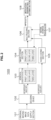
- FIG. 2 illustrates an exemplary configuration of the TV transmitter 100.
- the TV transmitter 100 includes an original moving image data supply section 101, a decoding device 102, a hierarchical classification section 103, an image coding section 104, an audio coding section 105, a multiplexing section 106, an additional information producing section 107, and a modulation/transmitting antenna section 108.
- the original moving image data supply section 101 retrieves original moving image data (image data, audio data) stored in an appropriate professional compression format on a device such as a hard disk drive (HDD), and supplies the retrieved original moving image data to the decoding device 102.
- the decoding device 102 decodes the original moving image data, and outputs uncompressed image data and uncompressed audio data.
- the hierarchical classification section 103 classifies the image data of each picture constituting the uncompressed image data into multiple layers. For example, as illustrated in the drawing, image data is classified into the three layers of a first layer, a second layer, and a third layer.
- the hierarchical classification section 103 conducts classification so that, except for the lowest layer, the pictures belonging to each layer are equal in number to the pictures belonging to all lower layers, and in addition, are positioned in the temporal center between the pictures belonging to all lower layers.
- the image coding section 104 encodes the classified image data of each layer, and generates a video stream (video elementary stream) holding the coded image data of each layer.
- the image coding section 104 conducts coding such as H.264/AVC, for example, so that a referenced picture belongs to a layer of referencing image data and/or a lower layer than the layer of the referencing image data.
- FIG. 3 illustrates an example of hierarchical classification and image coding.
- This example is an example of classifying the image data of each picture into three layers from a first layer to a third layer.
- I pictures intra pictures
- P pictures predictive pictures
- An I picture does not reference another picture, while a P picture only references an I picture or a P picture. For this reason, the first layer is decodable with just first layer pictures.
- B pictures (bi-directional predictive pictures) are placed in the temporal center positions between the respective pictures in the first layer, and are made to belong to the second layer.
- the B pictures in the second layer are encoded so as to reference only pictures belonging to a combined layer of the second layer and/or the first layer.
- B pictures in the second layer are made to reference only I pictures and P pictures in the first layer.
- the second layer is decodable with just the first/second combined layer.
- the frame frequency is doubled when decoding the first/second combined layer.
- B pictures are placed in the temporal center positions between the respective pictures in the first/second combined layer, and are made to belong to the third layer.
- the B pictures in the third layer are made to reference only pictures belonging to the third layer and/or the first/second combined layer. For this reason, the third layer is decodable with just the first to third combined layer. Also, compared to the case of decoding the first/second combined layer only, the frame frequency is doubled when decoding the first to third combined layer.
- a P picture in the first layer references only the immediately previous I picture or P picture.
- a B picture in the second layer references only the immediately previous or immediately following I picture or P picture in the first layer.
- a B picture in the third layer references only the immediately previous or immediately following I picture, P picture, or B picture in the first/second combined layer.
- the image coding section 104 For each picture, the image coding section 104 adds layer identification information for identifying the layer containing the picture to the coded image data of each layer. In other words, the image coding section 104 places layer identification information (temporal_id) in the header part of the NAL unit (nal_unit) of each picture.
- FIG. 4 illustrates the placement position of the layer identification information (temporal_id).
- the layer identification information (temporal_id) is placed in the NAL unit header SVC extension (Header svc extension), for example.
- NAL unit header SVC extension Header svc extension
- the frame frequency of the first layer when the frame frequency of the first layer only is 30 fps, the frame frequency of the first/second combined layer is 60 fps, and the frame frequency of the first to third combined layer is 120 fps. Also, although not illustrated in the drawing, it is possible to similarly construct a fourth layer and fifth layer.
- the audio coding section 105 performs coding such as MPEG-2 Audio or AAC on the uncompressed audio data, and generates an audio stream (audio elementary stream).
- the multiplexing section 106 multiplexes the elementary streams output from the video encoder 132 and the audio encoder 133.
- the multiplexing section 106 then outputs a transport stream TS as transport data.
- the additional information producing section 107 produces, and sends to the multiplexing section 106, frame frequency information of the pictures in the lowest layer and layer number information indicating the number of the multiple layers.
- the multiplexing section 106 inserts this information into the transport layer. For example, in the descriptor loop under "ES_info_length" of a program map table (PMT), the multiplexing section 106 places a newly defined FPS descriptor (fps_descriptor) stating the frame frequency information and the layer number information, as illustrated in FIG. 5 .
- This descriptor loop is the place that states the property information of each elementary stream (elementary_stream).
- the FPS descriptor is treated as one descriptor included among the above.
- FIG. 6 illustrates example syntax of the FPS descriptor.
- the 8-bit field “descriptor_tag” indicates the class of the descriptor, and herein indicates that the descriptor is the FPS descriptor. For example, the currently unused "0xf0" is assigned.
- the 8-bit field “descriptor_length” indicates the immediately following byte length, and herein is "0x02".
- the 8-bit field "base” expresses the frame frequency information of pictures in the lowest layer, or in other words the frame frequency information of the first layer. For example, in the case of 30 fps as in the example illustrated in FIG. 3 , the value is "0x1e” indicating 30.
- the 8-bit field "max” expresses layer number information indicating the number of the multiple layers. For example, in the case of layers up to the third layer as in the example illustrated in FIG. 3 , the value is "0x03" indicating 3.
- the additional information producing section 107 transmits this information to the image coding section 104, as indicated by the dashed line.
- the image coding section 104 inserts FPS info (fps_info) including the "base” and "max” information as an "fps_info SEI message" in the "SEIs" part of the access unit.
- the multiplexing section 106 inserts identification information identifying the existence of that SEI message in the transport layer. For example, in the descriptor loop under "ES_info_length" of the program map table (PMT), the multiplexing section 106 places a newly defined FPS exist descriptor (fps_exit_descriptor), as illustrated in FIG. 7(a) .
- FPS exist descriptor fps_exit_descriptor
- the 8-bit field "descriptor_tag” indicates the class of the descriptor, and herein indicates that the descriptor is the FPS exist descriptor. For example, the currently unused "0xf2" is assigned.
- the 8-bit field “descriptor_length” indicates the immediately following byte length, and herein is "0x01”.
- the receiving side decoding side
- the receiving side decodes pictures with the desired "temporal_id”.
- the modulation/transmitting antenna section 108 modulates the transport stream TS according to a modulation scheme suited to broadcasting, such as QPSK/OFDM.
- the modulation/transmitting antenna section 108 then transmits an RF modulated signal from a transmitting antenna.
- Original moving image data (image data, audio data) stored in an appropriate professional compression format is supplied from the original moving image data supply section 101 to the decoding device 102.
- the decoding device 102 the original moving image data is decoded, and uncompressed image data and uncompressed audio data are obtained.
- the uncompressed image data obtained by the decoding device 102 is supplied to the hierarchical classification section 103.
- the image data of each picture constituting the uncompressed image data is classified into multiple layers. In this case, pictures are classified so that, except for the lowest layer, the pictures belonging to each layer are equal in number to the pictures belonging to all lower layers, and in addition, are positioned in the temporal center between the pictures belonging to all lower layers (see FIG. 3 ).
- the image data of each layer hierarchically classified in this way is supplied to the image coding section 104.
- the classified image data of each layer is decoded, and a video stream (video elementary stream) holding the coded image data of each layer is generated.
- coding such as H.264/AVC is conducted, so that a referenced picture belongs to a layer of referencing image data and/or a lower layer than the layer of the referencing image data.
- layer identification information for identifying the layer containing the picture is added to the coded image data of each layer.
- layer identification information (temporal_id) is placed in the header part of the NAL unit (nal _unit) of each picture (see FIG. 4 ).
- the uncompressed audio data obtained by the decoding device 102 is supplied to the audio coding section 105.
- coding such as MPEG-2 Audio or AAC is performed on the uncompressed audio data, and an audio stream (audio elementary stream) is generated.
- the video stream generated by the image coding section 104 and the audio stream generated by the audio coding section 105 are supplied to the multiplexing section 106.
- the elementary streams are multiplexed, and a transport stream TS is obtained as transport data.
- frame frequency information of the pictures in the lowest layer and layer number information indicating the number of the multiple layers is produced, and added to the transport layer (container layer).
- the FPS descriptor stating the frame frequency information and the layer number information is placed in the descriptor loop under "ES_info_length" of the program map table (PMT) (see FIGS. 5 and 6 ).
- the frame frequency information and the layer number information may also be inserted in the video layer, such as, for example, an SEI message in the "SEIs” part of the access unit.
- FPS info (fps_info) including the information is inserted as an "fps_info SEI message" in the "SEIs” part of the access unit (see FIG. 7(b) ).
- identification information identifying the existence of the SEI message is inserted into the transport layer (container layer).
- the FPS exist descriptor fps_exit_descriptor
- PMT program map table
- the transport stream TS generated by the multiplexing section 106 is sent to the modulation/transmitting antenna section 108.
- the transport stream TS is modulated according to a modulation scheme suited to broadcasting, such as QPSK/OFDM, and an RF modulated signal is generated.
- the RF modulated signal is transmitted from a transmitting antenna.
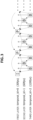
- FIG. 8 illustrates an exemplary configuration of the TV receiver 200.
- the TV receiver 200 includes a receiving antenna/demodulation section 201, a demultiplexing section 202, a control section 203, an image decoding section 204, a playback speed adjustment section 205, an image display section 206, an audio decoding section 207, and an audio output section 208.
- the receiving antenna/demodulation section 201 demodulates an RF modulated signal received with a receiving antenna, and acquires a transport stream TS.
- the demultiplexing section 202 respectively extracts the video stream and the audio stream from the transport stream TS.
- the image data of each picture constituting moving image data is classified into multiple layers, in which the image data is coded so that a referenced picture belongs to a layer of referencing image data and/or a lower layer than the layer of the referencing image data.
- the demultiplexing section 202 extracts, and transmits to the control section 203, various information inserted into the transport layer (container layer) of the transport stream TS.
- the FPS descriptor fps_descriptor placed in the descriptor loop under "ES_info_length" of the program map table (PMT) is also extracted.
- FPS descriptor frame frequency information of the pictures in the lowest layer and layer number information indicating the number of the multiple layers is stated.
- the FPS exist descriptor fps_exit_descriptor placed in the descriptor loop under "ES_info_length" of the program map table (PMT) may be extracted.
- the image decoding section 204 selectively retrieves and decodes the coded image data in a prescribed layer and lower layers from the video stream demultiplexed by the demultiplexing section 202, and obtains the image data of each picture. At this point, the image decoding section 204 retrieves and decodes the coded image data of pictures in a desired layer on the basis of layer identification information (temporal _id) placed in the header part of the NAL unit of each picture.
- the playback speed adjustment section 205 adjusts the speed of image playback according to the decoded image data of each picture, so as to match the frame frequency of the pictures in the prescribed layer. In other words, the playback speed adjustment section 205 successively outputs the decoded image data of each picture to match the frame frequency (frame rate) of pictures in the prescribed layer.
- the control section 203 controls the operation of each part of the TV receiver 200.
- the control section 203 controls the decoding layer by transmitting, to the image decoding section 204, decoding layer information specifying the prescribed layer and lower layers to be decoded.
- the control section 203 controls the image playback speed by transmitting, to the playback speed adjustment section 205, playback speed information corresponding to the frame frequency of the pictures in the prescribed layer, such as a synchronization signal, for example.
- the control section 203 controls the decoding layer in the image decoding section 204 and the image playback speed in the playback speed adjustment section 205 on the basis of the frame frequency information, the layer number information, and the decoding performance of the TV receiver 200 itself. For example, consider the case of the FPS descriptor (fps_descriptor) having stated content as illustrated in FIG. 6 .
- the image display section 206 is made up of a display such as a liquid crystal display (LCD).
- the image display section 206 displays images according to the image data of each picture output from the playback speed adjustment section 205.
- the audio decoding section 207 performs decoding on the audio stream demultiplexed by the demultiplexing section 202, and obtains audio data corresponding to the image data obtained by the image decoding section 204.
- the audio output section 208 is made up of components such as an amp and speakers. The audio output section 208 outputs audio according to the audio data output from the audio decoding section 207.
- the receiving antenna/demodulation section 201 an RF modulated signal received with a receiving antenna is demodulated, and a transport stream TS is acquired.
- This transport stream TS is supplied to the demultiplexing section 202.
- the video stream and the audio stream are respectively extracted from the transport stream TS.
- the image data of each picture constituting moving image data is classified into multiple layers, in which the image data is coded so that a referenced picture belongs to a layer of referencing image data and/or a lower layer than the layer of the referencing image data.
- the demultiplexing section 202 various information inserted into the transport layer (container layer) of the transport stream TS is extracted and transmitted to the control section 203.
- the FPS descriptor fps_descriptor placed in the descriptor loop under "ES_info_length" of the program map table (PMT) is also extracted.
- FPS descriptor frame frequency information of the pictures in the lowest layer and layer number information indicating the number of the multiple layers is stated.
- the FPS exist descriptor fps_exit_descriptor placed in the descriptor loop under "ES_info_length" of the program map table (PMT) may be extracted.
- control section 203 it is determined up to which layer is decodable, on the basis of the frame frequency information, layer number information, and decoding performance of the TV receiver 200 itself.
- the decoding layer in the image decoding section 204 is controlled, and the image playback speed in the playback speed adjustment section 205 is controlled.
- the video stream demultiplexed by the demultiplexing section 202 is supplied to the image decoding section 204.
- the image decoding section 204 under control by the control section 203, the coded image data in a prescribed layer and lower layers is selectively retrieved and decoded from the video stream, and the image data of each picture is successively obtained.
- the image data of each picture decoded in this way is supplied to the playback speed adjustment section 205.
- the speed of image playback according to the image data of each picture is adjusted so as to match the frame frequency of the pictures in the prescribed layer.
- the image data of each picture is successively output to match the frame frequency (frame rate) of pictures in the prescribed layer.
- the image data is supplied to the image display section 206, and images according to the image data of each picture in the prescribed layer and lower layers are displayed.
- the audio stream demultiplexed by the demultiplexing section 202 is supplied to the audio decoding section 207.
- decoding is performed on the audio stream, and audio data corresponding to the image data obtained by the image decoding section 204 is obtained.
- the audio data is supplied to the audio output section 208, and audio corresponding to the displayed images is output.
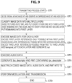
- the flowchart in FIG. 9 illustrates an example of a transmitting processing sequence in the TV transmitter 100 illustrated in FIG. 2 , in the case in which the FPS descriptor (fps_descriptor) is placed under the PMT. Note that in the TV transmitter 100 illustrated in FIG. 2 , in the image coding section 104, a single video stream holding the coded image data of pictures in respective layers is generated, as discussed earlier.
- FPS descriptor fps_descriptor
- step ST1 the TV transmitter 100 starts the transmitting process. Subsequently, in step ST2, the TV transmitter 100 decodes original moving image data, and generates uncompressed image data and audio data.
- step ST3 the TV transmitter 100 classifies the image data of each picture into multiple layers.
- the pictures (frames) are divided into two, and every other one is put into the third layer.
- the other pictures (frames) are divided into two again, and every other one is put into the second layer, while the remaining are put into the first layer.
- the TV transmitter 100 encodes the image data of each hierarchically classified picture.
- the first layer is encoded.
- the second layer is encoded.
- the third layer is encoded. In this case, references are made possible within the first layer to the third layer.
- the TV transmitter 100 places layer identification information (temporal _id) in the header part of the NAL unit (nal_unit) of each picture.
- step ST5 the TV transmitter 100 encodes the audio data. Subsequently, in step ST6, the TV transmitter 100 generates the FPS descriptor (fps_descriptor) and the PMT containing the FPS descriptor.
- step ST7 the TV transmitter 100 multiplexes the coded image data, audio data, and PMT into a transport stream TS. Subsequently, in step ST8, the TV transmitter 100 modulates and transmits the transport stream TS. After that, in step ST9, the TV transmitter 100 ends the process.
- the flowchart in FIG. 10 illustrates an example of a receiving processing sequence in the TV receiver 200 illustrated in FIG. 8 , in the case in which the FPS descriptor (fps_descriptor) is placed in the descriptor loop under "ES_info_length" of the PMT.
- This receiving processing sequence corresponds to the transmitting processing sequence illustrated by the flowchart in FIG. 9 discussed above.
- step ST11 the TV receiver 200 starts the receiving process. Subsequently, in step ST12, the TV receiver 200 receives and demodulates the RF modulated signal (broadcast signal), and obtains the transport stream TS.
- step ST12 the TV receiver 200 receives and demodulates the RF modulated signal (broadcast signal), and obtains the transport stream TS.
- step ST13 the TV receiver 200 extracts image data, audio data, and the PMT from the transport stream TS. Subsequently, in step S14, the TV receiver 200 extracts the FPS descriptor (fps_descriptor) from the PMT, compares the FPS descriptor to the decoding performance of the TV receiver 200 itself, and decides the layer to decode.
- FPS descriptor fps_descriptor
- step ST15 the TV receiver 200 decodes the image data of pictures in the layer decided in step ST14. Subsequently, playback is conducted at a suitable playback speed from the content of the FPS descriptor (fps_descriptor). Additionally, in step ST16, the TV receiver 200 decodes and plays back audio data. After that, in step ST17, the TV receiver 200 ends the process.
- FPS descriptor fps_descriptor
- the flowchart in FIG. 11 illustrates an example of a transmitting processing sequence in the TV transmitter 100 illustrated in FIG. 2 , in the case of adding an FPS info (fps_info) SEI message. Note that in the TV transmitter 100 illustrated in FIG. 2 , in the image coding section 104, a single video stream holding the coded image data in respective layers is generated, as discussed earlier.
- FPS info fps_info
- step ST21 the TV transmitter 100 starts the transmitting process. Subsequently, in step ST22, the TV transmitter 100 decodes original moving image data, and generates uncompressed image data and audio data.
- step ST23 the TV transmitter 100 classifies the image data of each picture into multiple layers.
- the pictures (frames) are divided into two, and every other one is put into the third layer. Additionally, the other pictures (frames) are divided into two again, and every other one is put into the second layer, while the remaining are put into the first layer.
- the TV transmitter 100 encodes the image data of each hierarchically classified picture.
- the first layer is encoded.
- the second layer is encoded.
- the third layer is encoded. In this case, references are possible within the first layer to the third layer.
- the TV transmitter 100 places layer identification information (temporal_id) in the header part of the NAL unit (nal_unit) of each picture.
- the TV transmitter 100 adds an FPS info (fps_info) SEI message.
- step ST25 the TV transmitter 100 encodes the audio data. Subsequently, in step ST26, the TV transmitter 100 generates the FPS exist descriptor (fps_exist_descriptor) and the PMT containing the FPS exist descriptor.
- FPS exist descriptor fps_exist_descriptor
- step ST27 the TV transmitter 100 multiplexes the coded image data, audio data, and PMT into a transport stream TS. Subsequently, in step ST28, the TV transmitter 100 modulates and transmits the transport stream TS. After that, in step ST29, the TV transmitter 100 ends the process.
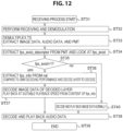
- the flowchart in FIG. 12 illustrates an example of a receiving processing sequence in the TV receiver 200 illustrated in FIG. 8 , in the case in which an FPS info (fps_info) SEI message is added.
- This receiving processing sequence corresponds to the transmitting processing sequence illustrated by the flowchart in FIG. 11 discussed above.
- step ST31 the TV receiver 200 starts the receiving process. Subsequently, in step ST32, the TV receiver 200 receives and demodulates the RF modulated signal (broadcast signal), and obtains the transport stream TS.
- step ST33 the TV receiver 200 extracts image data, audio data, and the PMT from the transport stream TS.
- step ST36 the TV receiver 200 extracts the FPS info (fps_info) added as an SEI message, compares the FPS info to the decoding performance of the TV receiver 200 itself, and decides the layer to decode.
- step ST37 the TV receiver 200 decodes the image data of pictures in the layer decided in step ST36. Subsequently, playback is conducted at a suitable playback speed from the content of the FPS info (fps_info). Additionally, in step ST38, the TV receiver 200 decodes and plays back audio data. After that, in step ST39, the TV receiver 200 ends the process.
- step ST40 the TV receiver 200 decodes and plays back the image data normally. Additionally, in step ST38, the TV receiver 200 decodes and plays back audio data. After that, in step ST39, the TV receiver 200 ends the process.
- the image data of each picture constituting moving image data is classified into multiple layers, and a video stream holding the coded image data of each layer is transmitted. For this reason, on the transmitting side, by simply transmitting one program or one file, a service supporting various frame frequencies may be provided, and a reduction in operating costs becomes possible.
- the coded image data in a prescribed layer and lower layers may be selectively retrieved and decoded, enabling playback at a frame frequency suited to the playback performance of the receiving side itself, thereby effectively promoting the adoption of receivers.
- image data is coded so that a referenced picture belongs to a layer of referencing image data and/or a lower layer than the layer of the referencing image data, and at a receiver, the playback performance of the receiving side itself may be used effectively without needing to decode layers higher than the prescribed layer.
- the image coding section 104 generates a single video stream holding the encoded image data of each layer, and for each picture, adds layer identification information (temporal_id) for identifying the layer containing the picture to the coded image data of each layer. For this reason, on the receiving side, it is possible to conduct good selective retrieval of coded image data in a prescribed layer and lower layers, on the basis of the layer identification information.
- the hierarchical classification section 103 classifies the image data of each picture constituting the moving image data into multiple layers so that, except for the lowest layer, the pictures belonging to each layer are equal in number to the pictures belonging to all lower layers, and in addition, are positioned in the temporal center between the pictures belonging to all lower layers. For this reason, the frame frequency doubles every time the layer is raised by one, and thus on the receiving side, it becomes possible to easily recognize the frame frequency in each layer with only the frame frequency information of the pictures in the lowest layer.
- frame frequency information of the pictures in the lowest layer and layer number information indicating the number of the multiple layers is inserted into the container layer (transport layer) or the video layer. For this reason, on the receiving side, it becomes possible to easily acquire the frame frequency information of the pictures in the lowest layer and the layer number information indicating the number of the multiple layers.
- the foregoing embodiment illustrates an example in which, in the image coding section 104, a single video stream holding the coded image data of each layer is generated, or in other words, an example of the same PID.
- the image coding section 104 it is also conceivable for multiple video streams holding the image data of each of multiple layers to be generated.
- a different PID is assigned to each layer.
- Respectively different PIDs are assigned when multiplexing the NAL units of each layer separated by the hierarchical layering of the video layer into transport stream packets. In comparison to the case of putting all layers into the same PID as in the embodiment discussed above, differences such as the following exist.
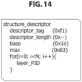
- a structure descriptor (structure_descriptor) is placed in the descriptor loop under "program_info_length" of the PMT, for example.
- FIG. 14 illustrates example syntax of the structure descriptor.
- the 8-bit field “descriptor_tag” indicates the class of the descriptor, and herein indicates that the descriptor is the structure descriptor. For example, the currently unused "0xf1" is assigned.
- the 8-bit field "descriptor_length” indicates the immediately following byte length.
- the 8-bit field "base” expresses the frame frequency information of pictures in the lowest layer, or in other words the frame frequency information of the first layer. For example, in the case of 30 fps as in the example illustrated in FIG. 13 , the value is "0x1e” indicating 30.
- the 8-bit field "max” expresses layer number information indicating the number of the multiple layers. For example, in the case of layers up to the third layer as in the example illustrated in FIG. 13 , the value is "0x03" indicating 3.
- the PIDs assigned to each layer are all stated.
- the statement order is sequential from the first layer, for example.
- the TS packets of which PIDs should be acquired is known from the value of "base” and the listed PIDs.
- the FPS info (fps_info) SEI message illustrated in FIG. 15(b) with different PIDs.
- the structure descriptor (structure_descriptor) illustrated in FIG. 15(a) is placed in the descriptor loop under "program_info_length”.
- TS packets of the PID of the first layer stated at the beginning of the for loop of the structure descriptor are acquired, and the SEI message inside, that is, the FPS info (fps_info), is extracted.
- the layer to be decoded is judged from the value of "base”, the PIDs of the TS packets to be acquired are detected from the "layer_PID" of the structure descriptor, and the desired TS packets are acquired and decoded.
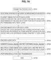
- the flowchart in FIG. 16 illustrates an example of a transmitting processing sequence for the case of being configured so that the TV transmitter 100 codes the image data of each layer in different PIDs, and the FPS descriptor (structure_descriptor) is placed under the PMT.
- step ST51 the TV transmitter 100 starts the transmitting process. Subsequently, in step ST52, the TV transmitter 100 decodes original moving image data, and generates uncompressed image data and audio data.
- step ST53 the TV transmitter 100 classifies the image data of each picture into multiple layers.
- the pictures (frames) are divided into two, and every other one is put into the third layer. Additionally, the other pictures (frames) are divided into two again, and every other one is put into the second layer, while the remaining are put into the first layer.
- the TV transmitter 100 encodes the image data of each hierarchically classified picture.
- the first layer is encoded. In this case, references are possible only within the first layer.
- the second layer is encoded. In this case, references are possible within the first layer and the second layer.
- the third layer is encoded. In this case, references are possible within the first layer to the third layer.
- step ST55 the TV transmitter 100 encodes the audio data. Subsequently, in step ST56, the TV transmitter 100 generates the structure descriptor (structure_descriptor) and the PMT containing the FPS exist descriptor.
- step ST57 the TV transmitter 100 multiplexes the coded image data, audio data, and PMT into a transport stream TS. Subsequently, the TV transmitter 100 multiplexes the image data with different PIDs for each layer. Subsequently, in step ST58, the TV transmitter 100 modulates and transmits the transport stream TS. After that, in step ST59, the TV transmitter 100 ends the process.
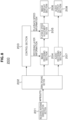
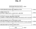
- the flowchart in FIG. 17 illustrates an example of a receiving processing sequence in the TV receiver 200 illustrated in FIG. 8 , in the case in which the image data of each layer is encoded with different PIDs, and the structure descriptor (structure_descriptor) is placed under the PMT.
- This receiving processing sequence corresponds to the transmitting processing sequence illustrated by the flowchart in FIG. 16 discussed above.
- step ST61 the TV receiver 200 starts the receiving process. Subsequently, in step ST62, the TV receiver 200 receives and demodulates the RF modulated signal (broadcast signal), and obtains the transport stream TS.
- step ST62 the TV receiver 200 receives and demodulates the RF modulated signal (broadcast signal), and obtains the transport stream TS.
- step ST63 the TV receiver 200 extracts image data, audio data, and the PMT from the transport stream TS. Subsequently, in step S64, the TV receiver 200 extracts the structure descriptor (structure_descriptor) from the PMT, compares the structure descriptor to the decoding performance of the TV receiver 200 itself, and decides the layer to decode.
- structure_descriptor structure descriptor
- step ST65 the TV receiver 200 decodes, from the TS packets of each PID, the image data of pictures in the layer decided in step ST64. Subsequently, playback is conducted at a suitable playback speed from the content of the structure descriptor (structure_descriptor). Additionally, in step ST66, the TV receiver 200 decodes and plays back audio data. After that, in step ST67, the TV receiver 200 ends the process.
- the flowchart in FIG. 18 illustrates an example of a transmitting processing sequence for the case in which the TV transmitter 100 codes the image data of each layer with different PIDs, and adds an FPS info (fps_info) SEI message.
- step ST71 the TV transmitter 100 starts the transmitting process. Subsequently, in step ST72, the TV transmitter 100 decodes original moving image data, and generates uncompressed image data and audio data.
- step ST73 the TV transmitter 100 classifies the image data of each picture into multiple layers.
- the pictures (frames) are divided into two, and every other one is put into the third layer. Additionally, the other pictures (frames) are divided into two again, and every other one is put into the second layer, while the remaining are put into the first layer.
- step ST74 the TV transmitter 100 encodes the image data of each hierarchically classified picture.
- the first layer is encoded. In this case, references are possible only within the first layer.
- the second layer is encoded. In this case, references are possible within the first layer and the second layer.
- the third layer is encoded. In this case, references are possible within the first layer to the third layer.
- the TV transmitter 100 adds an FPS info (fps_info) SEI message.
- step ST75 the TV transmitter 100 encodes the audio data. Subsequently, in step ST76, the TV transmitter 100 generates the structure descriptor (structure_descriptor) and the PMT containing the FPS exist descriptor.
- step ST77 the TV transmitter 100 multiplexes the coded image data, audio data, and PMT into a transport stream TS. Subsequently, the TV transmitter 100 multiplexes the image data with different PIDs for each layer. Subsequently, in step ST78, the TV transmitter 100 modulates and transmits the transport stream TS. After that, in step ST79, the TV transmitter 100 ends the process.
- the flowchart in FIG. 19 illustrates an example of a receiving processing sequence in the TV receiver 200 illustrated in FIG. 8 , in the case in which the image data of each layer is coded with different PIDs, and an FPS info (fps_info) SEI message is added.
- This receiving processing sequence corresponds to the transmitting processing sequence illustrated by the flowchart in FIG. 18 discussed above.
- step ST81 the TV receiver 200 starts the receiving process. Subsequently, in step ST82, the TV receiver 200 receives and demodulates the RF modulated signal (broadcast signal), and obtains the transport stream TS.
- step ST83 the TV receiver 200 extracts image data, audio data, and the PMT from the transport stream TS.
- step S84 the TV receiver 200 extracts the structure descriptor (structure_descriptor) from the PMT.
- step ST85 the TV receiver 200 judges whether or not the structure descriptor exists.
- step ST86 the TV receiver 200 extracts the FPS info (fps_info) added as an SEI message, compares the FPS info to the decoding performance of the TV receiver 200 itself, and decides the layer to decode.
- step ST77 the TV receiver 200 decodes, from the TS packets of each PID, the image data of pictures in the layer decided in step ST76. Subsequently, playback is conducted at a suitable playback speed from the content of the FPS info (fps_info). Additionally, in step ST88, the TV receiver 200 decodes and plays back audio data. After that, in step ST89, the TV receiver 200 ends the process.
- step ST90 the TV receiver 200 decodes and plays back the image data normally. Additionally, in step ST88, the TV receiver 200 decodes and plays back audio data. After that, in step ST89, the TV receiver 200 ends the process.
- FIG. 20 illustrates a comparison of additional information for the above four methods of (a) syntax statements with the same PID (PES) and in the PMT, (b) syntax statements with the same PID (PES) and in the SEI, (c) syntax statements in different PIDs (PES) and in the PMT, and (d) syntax statements in different PIDs (PES) and in the SEI.
- the foregoing embodiments illustrates an example of classifying the image data of each picture constituting the moving image data into multiple layers so that, except for the lowest layer, the pictures belonging to each layer are equal in number to the pictures belonging to all lower layers, and in addition, are positioned in the temporal center between the pictures belonging to all lower layers.
- the classification method is not limited to such an example. For example, classification methods like the following are also possible.
- FIG. 21(a) illustrates another example of hierarchical classification and image coding.
- This example is an example of classifying the image data of each picture into the two layers of a first layer and a second layer.
- I pictures and P pictures are made to belong to the first layer.
- An I picture does not reference another picture, while a P picture only references an I picture or a P picture. For this reason, the first layer is decodable with just first layer pictures.
- two B pictures are placed at equal intervals temporally between each picture in the first layer, and are made to belong to the second layer.
- the B pictures in the second layer are encoded so as to only reference pictures belonging to the second layer and/or the first layer. For this reason, the second layer is decodable with just the first/second combined layer.
- the frame frequency is tripled when decoding the first/second combined layer. Consequently, as illustrated in the drawing, when the frame frequency of the first layer only is 40 fps, the frame frequency of the first/second combined layer is 120 fps.
- layer identification information for identifying the layer containing the picture is added to the coded image data of each layer.
- layer identification information (temporal_id) is placed in the header part of the NAL unit (nal _unit) of each picture.
- FIG. 21(b) illustrates example syntax of the FPS descriptor (fps_descriptor) in the case in which hierarchical classification and image coding as illustrated in FIG. 21(a) is conducted.
- the 8-bit field “descriptor_tag” indicates the class of the descriptor, and herein indicates that the descriptor is the FPS descriptor. For example, the currently unused "0xf0" is allocated.
- the 8-bit field "descriptor_length” indicates the immediately following byte length.
- the 8-bit field "base” expresses the frame frequency information of pictures in the lowest layer, or in other words the frame frequency information of the first layer.
- the value is "0x28" indicating 40.
- the 8-bit field "max” expresses layer number information indicating the number of the multiple layers.
- the value is "0x02" indicating 2.
- the multiples of the frame frequency in the combined layer up to each layer in the second layer and subsequent layers versus the frame frequency of the first layer are all stated.
- the value is "0x03" for the second layer, which states that the multiple is 3x.
- FIG. 22(a) also illustrates another example of hierarchical classification and image coding.
- This example is an example of classifying the image data of each picture into the two layers of a first layer and a second layer.
- I pictures and P pictures are made to belong to the first layer.
- An I picture does not reference another picture, while a P picture only references an I picture or a P picture. For this reason, the first layer is decodable with just first layer pictures.
- the frame frequency of the first layer is 24 fps, the frame frequency of the first/second combined layer is 120 fps.
- layer identification information for identifying the layer containing the picture is added to the coded image data of each layer.
- layer identification information (temporal_id) is placed in the header part of the NAL unit (nal _unit) of each picture.
- FIG. 22(b) illustrates example syntax of the FPS descriptor (fps_descriptor) in the case in which hierarchical classification and image coding as illustrated in FIG. 22(a) is conducted.
- the 8-bit field “descriptor_tag” indicates the class of the descriptor, and herein indicates that the descriptor is the FPS descriptor. For example, the currently unused "0xf0" is allocated.
- the 8-bit field "descriptor_length” indicates the immediately following byte length.
- the 8-bit field "base” expresses the frame frequency information of pictures in the lowest layer, or in other words the frame frequency information of the first layer.
- the value is "0x18" indicating 24.
- the 8-bit field "max” expresses layer number information indicating the number of the multiple layers.
- the value is "0x02" indicating 2.
- the multiples of the frame frequency in the combined layer up to each layer in the second layer and subsequent layers versus the frame frequency of the first layer are all stated.
- the value is "0x05" for the second layer, which states that the multiple is 5x.
- FIG. 23(a) also illustrates another example of hierarchical classification and image coding.
- This example is an example of classifying the image data of each picture into the four layers from the first layer to the fourth layer.
- I pictures and P pictures are made to belong to the first layer.
- An I picture does not reference another picture, while a P picture only references an I picture or a P picture. For this reason, the first layer is decodable with just first layer pictures.
- B pictures (bi-directional predictive pictures) are placed in the temporal center positions between the respective pictures in the first layer, and are made to belong to the second layer.
- the B pictures in the second layer are encoded so as to reference only pictures belonging to a combined layer of the second layer and/or the first layer. For this reason, the second layer is decodable with just the first/second combined layer.
- the frame frequency is doubled when decoding the first/second combined layer. Consequently, as illustrated in the drawing, when the frame frequency of the first layer only is 12 fps, the frame frequency of the first/second combined layer is 24 fps.
- the frame frequency of the first layer is 12 fps
- the frame frequency of the first to third combined layers is 60 fps.
- B pictures (bi-directional predictive pictures) are placed in the temporal center positions between the respective pictures in the first layer and the third layer, and are made to belong to the fourth layer.
- the B pictures in the fourth layer are encoded so as to only reference pictures belonging to the fourth layer and/or the third layer or below. For this reason, the fourth layer is decodable with the first to fourth combined layer only.
- the frame frequency is ten times when decoding from the first to fourth combined layers. Consequently, as illustrated in the drawing, when the frame frequency of the first layer only is 12 fps, the frame frequency of the first to second combined layers is 120 fps.
- layer identification information for identifying the layer containing the picture is added to the coded image data of each layer.
- layer identification information (temporal _id) is placed in the header part of the NAL unit (nal _unit) of each picture.
- FIG. 23(b) illustrates example syntax of the FPS descriptor (fps_descriptor) in the case in which hierarchical classification and image coding as illustrated in FIG. 23(a) is conducted.
- the 8-bit field “descriptor_tag” indicates the class of the descriptor, and herein indicates that the descriptor is the FPS descriptor. For example, the currently unused "0xf0" is allocated.
- the 8-bit field "descriptor_length” indicates the immediately following byte length.
- the 8-bit field "base” expresses the frame frequency information of pictures in the lowest layer, or in other words the frame frequency information of the first layer.
- the value is "0x0C” indicating 12.
- the 8-bit field "max” expresses layer number information indicating the number of the multiple layers.
- the value is "0x04” indicating 4.
- the multiples of the frame frequency in the combined layer up to each layer in the second layer and subsequent layers versus the frame frequency of the first layer are all stated.
- the value is "0x03" for the second layer, which states that the multiple is 2x.
- the value is "0x05” for the third layer, which states that the multiple is 5x.
- the value is "0x0a” for the fourth layer, which states that the multiple is 10x.
- part of the TV receiver 200 may also be a configuration of a set-top box and a monitor or the like connected by a digital interface such as High-Definition Multimedia Interface (HDMI), for example.
- HDMI High-Definition Multimedia Interface
- the foregoing embodiments illustrate an example in which the container is a transport stream (MPEG-2 TS).
- the present technology is similarly applicable to systems configured for delivery to a receiving terminal using a network such as the Internet.
- content is often delivered in a container for MP4 or some other format.
- containers of various formats such as the transport stream (MPEG-2 TS) adopted in digital broadcasting standards, or MP4 being used for Internet delivery.
- a main feature of the present technology is that the image data of each picture constituting moving image data is classified into multiple layers, the image data of each layer is coded so that a referenced picture belongs to a layer of referencing image data or a lower layer than the layer of the referencing image data, and a video stream holding the coded image data of each layer is transmitted in a container of a predetermined format, thereby enabling a high frame frequency service to be achieved with ease.
Landscapes
- Engineering & Computer Science (AREA)
- Multimedia (AREA)
- Signal Processing (AREA)
- Compression Or Coding Systems Of Tv Signals (AREA)
- Two-Way Televisions, Distribution Of Moving Picture Or The Like (AREA)
Claims (5)
- Empfangsvorrichtung (200), umfassend:einen Empfangsabschnitt, der konfiguriert ist, um einen Container in einem vorgeschriebenen Format zu empfangen, wobei der Container einen Videostrom von Bilddaten einschließt, wobei die Bilddaten in eine Vielzahl von Ebenen eingeteilt sind, wobei jede Ebene Bilddaten von Abbildungen aufweist, die Bewegtbilddaten ausmachen;einen Bilddecodierungsabschnitt (204), der konfiguriert ist, um codierte Bilddaten einer ausgewählten Ebene und einer oder mehrerer Ebenen, die niedriger als die ausgewählte Ebene sind, aus dem in dem empfangenen Container eingeschlossenen Videostrom selektiv abzurufen und zu decodieren, um decodierte Bewegtbilddaten der ausgewählten Ebene zu erhalten;einen Abschnitt (205) für eine Anpassung der Wiedergabegeschwindigkeit, der konfiguriert ist, um eine Geschwindigkeit einer Bildwiedergabe gemäß den decodierten Bilddaten anzupassen, um sie auf eine Einzelbildfrequenz von Abbildungen in der ausgewählten Ebene abzustimmen;einen Steuerabschnitt (203), der konfiguriert ist, um den Abschnitt für die Anpassung der Wiedergabegeschwindigkeit zu steuern und um den Bilddecodierungsabschnitt zu steuern, undeinen Demultiplexabschnitt (202), der konfiguriert ist, um die Bilddaten jeder Abbildung, die Bewegtbilddaten ausmacht, in eine Vielzahl von Ebenen zu klassifizieren, so dass, mit Ausnahme einer niedrigsten Ebene, die zu jeder Ebene gehörenden Abbildungen in der Anzahl der zu allen niedrigeren Ebenen gehörenden Abbildungen entsprechen und zusätzlich in einer zeitlichen Mitte zwischen den zu allen niedrigeren Ebenen gehörenden Abbildungen positioniert sind, so dass die Bildfrequenz sich jedes Mal verdoppelt, wenn die Ebene um eins erhöht wird;wobei die in dem Container eingeschlossenen Informationen Frequenzinformationen zu Abbildungen in einer untersten Ebene und Ebenennummerninformationen einschließen, die die Anzahl der Vielzahl von Ebenen angeben; undwobei die in dem Container eingeschlossenen Informationen Ebenenidentifikationsinformationen zum Identifizieren jeder der Vielzahl von Ebenen einschließen, und der Bilddecodierungsabschnitt konfiguriert ist, um auf der Grundlage der Ebenenidentifikationsinformationen codierte Bilddaten in der ausgewählten Ebene und niedrigeren Ebenen aus dem Videostrom selektiv abzurufen und zu decodieren;dadurch gekennzeichnet, dassder Steuerabschnitt (203) konfiguriert ist, um die höchste decodierbare Ebene auf der Grundlage der Frequenzinformationen der Bilder in der untersten Ebene, der Anzahl der Vielzahl von Ebenen in dem Container und der Decodierungsleistung des Empfangsvorrichtung zu bestimmen.
- Empfangsvorrichtung nach Anspruch 1, wobei der Demultiplexabschnitt (202) ferner konfiguriert ist, um aus der Containerschicht einen FPS-Deskriptor (fps_descriptor) zu extrahieren, der in der Deskriptorschleife unter "ES_info_length" der Programmzuordnungstabelle (PMT) platziert ist, und um aus dem FPS-Deskriptor Frequenzinformationen der Abbildungen in der untersten Ebene und Ebenennummerninformationen zu erhalten, die die Anzahl der Vielzahl von Ebenen angeben.
- Empfangsvorrichtung nach einem der vorstehenden Ansprüche, wobei in dem Container eine Vielzahl von Videoströmen, die die codierten Bilddaten für jede der Vielzahl von Ebenen halten, eingeschlossen sind, Stromidentifikationsinformationen zum Identifizieren des Videostroms jeder Ebene in die Containerebene eingefügt sind und der Bildcodierungsabschnitt auf der Grundlage der Stromidentifikationsinformationen codierte Bilddaten aus den Videoströmen einer vorgeschriebenen Ebene und niedrigerer Ebenen selektiv abruft und decodiert.
- Empfangsverfahren, das durch eine Empfangsvorrichtung (200) durchgeführt wird, umfassend:Empfangen eines Containers in einem vorgeschriebenen Format, wobei der Container einen Videostrom von Bilddaten einschließt, wobei die Bilddaten in eine Vielzahl von Ebenen eingeteilt sind, wobei jede Ebene Bilddaten von Abbildungen aufweist, die Bewegtbilddaten ausmachen;selektives Abrufen und Decodieren codierter Bilddaten einer ausgewählten Ebene und einer oder mehrerer Ebenen, die niedriger als die ausgewählte Ebene sind, aus dem in dem empfangenen Container eingeschlossenen Videostrom, um decodierte Bewegtbilddaten der ausgewählten Ebene zu erhalten;Anpassen einer Geschwindigkeit der Bildwiedergabe gemäß den decodierten Bilddaten, um sie auf eine Einzelbildfrequenz von Abbildungen in der ausgewählten Ebene abzustimmen;Klassifizieren der Bilddaten jeder Abbildung, die Bewegtbilddaten ausmacht, in eine Vielzahl von Ebenen, so dass, mit Ausnahme einer niedrigsten Ebene, die zu jeder Ebene gehörenden Abbildungen in der Anzahl der zu allen niedrigeren Ebenen gehörenden Abbildungen entsprechen und zusätzlich in einer zeitlichen Mitte zwischen den zu allen niedrigeren Ebenen gehörenden Abbildungen positioniert sind, so dass die Bildfrequenz sich jedes Mal verdoppelt, wenn die Ebene um eins erhöht wird;wobei die in dem Container eingeschlossenen Informationen Frequenzinformationen zu Abbildungen in einer untersten Ebene und Ebenennummerninformationen einschließen, die die Anzahl der Vielzahl von Ebenen, undwobei die in dem Container eingeschlossenen Informationen Ebenenidentifikationsinformationen zum Identifizieren jeder der Vielzahl von Ebenen einschließen, und der Bilddecodierungsabschnitt konfiguriert ist, um auf der Grundlage der Ebenenidentifikationsinformationen codierte Bilddaten in der ausgewählten Ebene und niedrigeren Ebenen aus dem Videostrom selektiv abzurufen und zu decodieren;gekennzeichnet durchBestimmen der höchsten decodierbaren Ebene auf der Grundlage der Frequenzinformationen der Bilder in der untersten Ebene, der Anzahl der Vielzahl von Ebenen in dem Container und der Dekodierungsleistung des Empfangsvorrichtung zu bestimmen.
- Empfangsverfahren nach Anspruch 4, umfassend das Extrahieren, aus der Containerschicht, eines FPS-Deskriptors (fps_descriptor), der in der Deskriptorschleife unter "ES_info_length" der Programmzuordnungstabelle (PMT) platziert ist, und um aus dem FPS-Deskriptor Frequenzinformationen der Abbildungen in der untersten Ebene und Ebenennummerninformationen zu erhalten, die die Anzahl der Vielzahl von Ebenen angeben.
Applications Claiming Priority (3)
| Application Number | Priority Date | Filing Date | Title |
|---|---|---|---|
| JP2012144979 | 2012-06-28 | ||
| EP13808997.4A EP2869555A4 (de) | 2012-06-28 | 2013-06-21 | Sende-/empfangsvorrichtung, verfahren und codierungs-/decodierungsvorrichtung |
| PCT/JP2013/067147 WO2014002914A1 (ja) | 2012-06-28 | 2013-06-21 | 送信/受信装置、方法、符号化/復号化装置 |
Related Parent Applications (1)
| Application Number | Title | Priority Date | Filing Date |
|---|---|---|---|
| EP13808997.4A Division EP2869555A4 (de) | 2012-06-28 | 2013-06-21 | Sende-/empfangsvorrichtung, verfahren und codierungs-/decodierungsvorrichtung |
Publications (2)
| Publication Number | Publication Date |
|---|---|
| EP3758376A1 EP3758376A1 (de) | 2020-12-30 |
| EP3758376B1 true EP3758376B1 (de) | 2025-03-05 |
Family
ID=49783066
Family Applications (2)
| Application Number | Title | Priority Date | Filing Date |
|---|---|---|---|
| EP20191575.8A Active EP3758376B1 (de) | 2012-06-28 | 2013-06-21 | Empfangsvorrichtung und entsprechendes verfahren |
| EP13808997.4A Withdrawn EP2869555A4 (de) | 2012-06-28 | 2013-06-21 | Sende-/empfangsvorrichtung, verfahren und codierungs-/decodierungsvorrichtung |
Family Applications After (1)
| Application Number | Title | Priority Date | Filing Date |
|---|---|---|---|
| EP13808997.4A Withdrawn EP2869555A4 (de) | 2012-06-28 | 2013-06-21 | Sende-/empfangsvorrichtung, verfahren und codierungs-/decodierungsvorrichtung |
Country Status (9)
| Country | Link |
|---|---|
| US (3) | US10250901B2 (de) |
| EP (2) | EP3758376B1 (de) |
| JP (1) | JP6576635B2 (de) |
| KR (1) | KR102161863B1 (de) |
| CN (1) | CN104396264B (de) |
| BR (1) | BR112014032108B1 (de) |
| IN (1) | IN2014MN02408A (de) |
| RU (1) | RU2641470C2 (de) |
| WO (1) | WO2014002914A1 (de) |
Families Citing this family (14)
| Publication number | Priority date | Publication date | Assignee | Title |
|---|---|---|---|---|
| US10595031B2 (en) | 2013-07-12 | 2020-03-17 | Qualcomm Incorporated | Selection of target output layers in high efficiency video coding extensions |
| JP5947269B2 (ja) * | 2013-09-24 | 2016-07-06 | ソニー株式会社 | 符号化装置、符号化方法、送信装置および受信装置 |
| US10284858B2 (en) * | 2013-10-15 | 2019-05-07 | Qualcomm Incorporated | Support of multi-mode extraction for multi-layer video codecs |
| JP5909026B2 (ja) * | 2013-10-18 | 2016-04-26 | パナソニック株式会社 | 画像符号化方法及び画像符号化装置 |
| CN106031174B (zh) | 2014-02-21 | 2019-10-29 | 索尼公司 | 传输装置、传输方法、接收装置以及接收方法 |
| JP5886341B2 (ja) | 2014-03-07 | 2016-03-16 | ソニー株式会社 | 送信装置、送信方法、受信装置および受信方法 |
| JP5836424B2 (ja) * | 2014-04-14 | 2015-12-24 | ソニー株式会社 | 送信装置、送信方法、受信装置および受信方法 |
| WO2015163267A1 (ja) * | 2014-04-25 | 2015-10-29 | ソニー株式会社 | 送信装置、送信方法、受信装置および受信方法 |
| JP6483028B2 (ja) * | 2014-05-23 | 2019-03-13 | パナソニック インテレクチュアル プロパティ コーポレーション オブ アメリカPanasonic Intellectual Property Corporation of America | 画像符号化方法及び画像符号化装置 |
| JP6768096B2 (ja) * | 2014-05-23 | 2020-10-14 | パナソニック インテレクチュアル プロパティ コーポレーション オブ アメリカPanasonic Intellectual Property Corporation of America | 画像符号化方法及び画像復号装置 |
| WO2016021365A1 (ja) * | 2014-08-07 | 2016-02-11 | ソニー株式会社 | 送信装置、送信方法および受信装置 |
| JP2017228895A (ja) * | 2016-06-21 | 2017-12-28 | Necプラットフォームズ株式会社 | 階層符号化信号間引き装置、制御方法およびプログラム |
| GB2553588B (en) | 2016-09-13 | 2020-06-24 | Ge Aviat Systems Ltd | Multi-semiconductor solid state power controllers and method for managing inductive switching transients thereof |
| JP6350638B2 (ja) * | 2016-11-16 | 2018-07-04 | ソニー株式会社 | 送信装置、送信方法、受信装置および受信方法 |
Family Cites Families (19)
| Publication number | Priority date | Publication date | Assignee | Title |
|---|---|---|---|---|
| KR100834750B1 (ko) | 2004-01-29 | 2008-06-05 | 삼성전자주식회사 | 엔코더 단에서 스케일러빌리티를 제공하는 스케일러블비디오 코딩 장치 및 방법 |
| AU2005267171A1 (en) | 2004-07-20 | 2006-02-02 | Qualcomm Incorporated | Method and apparatus for encoder assisted-frame rate up conversion (EA-FRUC) for video compression |
| BRPI0616615A8 (pt) | 2005-09-29 | 2018-03-06 | Thomson Res Funding Corporation | método e aparelho para codificação de vídeo com taxa de transferência variável (vbr) restrita |
| US8436889B2 (en) | 2005-12-22 | 2013-05-07 | Vidyo, Inc. | System and method for videoconferencing using scalable video coding and compositing scalable video conferencing servers |
| KR20070108433A (ko) * | 2006-01-09 | 2007-11-12 | 한국전자통신연구원 | 청크 디스크립터를 이용한 svc 파일포맷에서의 비디오데이터 공유방법 |
| US8693538B2 (en) | 2006-03-03 | 2014-04-08 | Vidyo, Inc. | System and method for providing error resilience, random access and rate control in scalable video communications |
| CA2644753A1 (en) | 2006-03-03 | 2007-09-13 | Vidyo, Inc. | System and method for providing error resilience, random access and rate control in scalable video communications |
| RU2395174C1 (ru) * | 2006-03-30 | 2010-07-20 | ЭлДжи ЭЛЕКТРОНИКС ИНК. | Способ и устройство для декодирования/кодирования сигнала видео |
| EP2041976A4 (de) * | 2006-07-12 | 2012-06-20 | Nokia Corp | Signalisierung von skalierbarkeitsinformationen der interessierenden region in mediadateien |
| WO2008048886A2 (en) | 2006-10-16 | 2008-04-24 | Vidyo, Inc. | Systems and methods for signaling and performing temporal level switching in scalable video coding |
| CN101796835B (zh) * | 2007-07-02 | 2012-08-08 | Lg电子株式会社 | 数字广播系统和数据处理方法 |
| US7953882B2 (en) * | 2007-07-26 | 2011-05-31 | Realnetworks, Inc. | Adaptive variable fidelity media distribution system and method |
| GB2456572B (en) * | 2008-01-18 | 2012-03-14 | Picochip Designs Ltd | Femtocell device |
| KR101580516B1 (ko) * | 2008-04-07 | 2015-12-28 | 엘지전자 주식회사 | 방송 신호 수신 방법 및 방송 신호 수신 장치 |
| US8300705B2 (en) * | 2008-12-08 | 2012-10-30 | Electronics And Telecommunications Research Institute | Method for generating and processing hierarchical PES packet for digital satellite broadcasting based on SVC video |
| CN101924944B (zh) | 2009-06-15 | 2013-06-05 | 华为技术有限公司 | 可伸缩视频编码操作点选择方法、信息提供方法及设备 |
| JP5407968B2 (ja) * | 2009-06-29 | 2014-02-05 | ソニー株式会社 | 立体画像データ送信装置および立体画像データ受信装置 |
| KR20120015260A (ko) * | 2010-07-20 | 2012-02-21 | 한국전자통신연구원 | 스케일러빌리티 및 뷰 정보를 제공하는 스트리밍 서비스를 위한 방법 및 장치 |
| EP2664151A4 (de) * | 2011-01-14 | 2016-01-20 | Vidyo Inc | Hochgeschichtete syntax für zeitliche skalierbarkeit |
-
2013
- 2013-06-21 IN IN2408MUN2014 patent/IN2014MN02408A/en unknown
- 2013-06-21 WO PCT/JP2013/067147 patent/WO2014002914A1/ja not_active Ceased
- 2013-06-21 RU RU2014151717A patent/RU2641470C2/ru active
- 2013-06-21 CN CN201380032438.1A patent/CN104396264B/zh active Active
- 2013-06-21 JP JP2014522604A patent/JP6576635B2/ja active Active
- 2013-06-21 US US14/399,282 patent/US10250901B2/en active Active
- 2013-06-21 EP EP20191575.8A patent/EP3758376B1/de active Active
- 2013-06-21 KR KR1020147035423A patent/KR102161863B1/ko active Active
- 2013-06-21 EP EP13808997.4A patent/EP2869555A4/de not_active Withdrawn
- 2013-06-21 BR BR112014032108-6A patent/BR112014032108B1/pt active IP Right Grant
-
2018
- 2018-12-18 US US16/223,154 patent/US10750199B2/en active Active
-
2020
- 2020-07-27 US US16/939,992 patent/US11979594B2/en active Active
Non-Patent Citations (1)
| Title |
|---|
| YING CHEN (QUALCOMM) ET AL: "Comments on the carriage of MVC over MPEG-2 Systems", no. M17025; m17025, 21 October 2009 (2009-10-21), XP030045615, Retrieved from the Internet <URL:http://phenix.int-evry.fr/mpeg/doc_end_user/documents/90_Xian/contrib/m17025.zip m17025.doc> [retrieved on 20100827] * |
Also Published As
| Publication number | Publication date |
|---|---|
| RU2014151717A (ru) | 2016-07-10 |
| US10750199B2 (en) | 2020-08-18 |
| US20150124884A1 (en) | 2015-05-07 |
| CN104396264A (zh) | 2015-03-04 |
| WO2014002914A1 (ja) | 2014-01-03 |
| KR102161863B1 (ko) | 2020-10-05 |
| EP3758376A1 (de) | 2020-12-30 |
| US10250901B2 (en) | 2019-04-02 |
| RU2641470C2 (ru) | 2018-01-17 |
| IN2014MN02408A (de) | 2015-08-21 |
| CN104396264B (zh) | 2019-04-02 |
| JP6576635B2 (ja) | 2019-09-18 |
| JPWO2014002914A1 (ja) | 2016-05-30 |
| BR112014032108B1 (pt) | 2022-12-27 |
| EP2869555A4 (de) | 2016-03-16 |
| EP2869555A1 (de) | 2015-05-06 |
| US11979594B2 (en) | 2024-05-07 |
| BR112014032108A2 (pt) | 2017-08-01 |
| US20190124352A1 (en) | 2019-04-25 |
| KR20150035699A (ko) | 2015-04-07 |
| US20200359044A1 (en) | 2020-11-12 |
Similar Documents
| Publication | Publication Date | Title |
|---|---|---|
| EP3758376B1 (de) | Empfangsvorrichtung und entsprechendes verfahren | |
| KR102130871B1 (ko) | 송신 장치, 송신 방법, 수신 장치 및 수신 방법 | |
| US20140150045A1 (en) | Reception/reproduction device, transmission device, reception/reproduction method and transmission method | |
| EP3051819B1 (de) | Codierungsvorrichtung, codierungsverfahren, übertragungsvorrichtung und empfangsvorrichtung | |
| JP6795076B2 (ja) | 送受信システムおよび送受信方法 | |
| US20130113883A1 (en) | Receiving device and output method | |
| US20120113220A1 (en) | Video output device, video output method, reception device and reception method | |
| JP5905147B2 (ja) | 送信装置、送信方法、受信装置および受信方法 | |
| JP6950802B2 (ja) | 送信方法および送信装置 | |
| JP7230981B2 (ja) | 受信装置および受信方法 | |
| JP6773205B2 (ja) | 送信装置、送信方法、受信装置および受信方法 | |
| JP2018011341A (ja) | 送信装置、送信方法、受信装置および受信方法 | |
| JP6213482B2 (ja) | 送信装置、送信方法、受信装置および受信方法 | |
| JP5905148B2 (ja) | 送信装置、送信方法、受信装置および受信方法 | |
| JPH10234017A (ja) | 映像データ送信方法及び映像データ再生装置及び映像音声データ再生装置 |
Legal Events
| Date | Code | Title | Description |
|---|---|---|---|
| PUAI | Public reference made under article 153(3) epc to a published international application that has entered the european phase |
Free format text: ORIGINAL CODE: 0009012 |
|
| STAA | Information on the status of an ep patent application or granted ep patent |
Free format text: STATUS: REQUEST FOR EXAMINATION WAS MADE |
|
| 17P | Request for examination filed |
Effective date: 20200818 |
|
| AC | Divisional application: reference to earlier application |
Ref document number: 2869555 Country of ref document: EP Kind code of ref document: P |
|
| AK | Designated contracting states |
Kind code of ref document: A1 Designated state(s): AL AT BE BG CH CY CZ DE DK EE ES FI FR GB GR HR HU IE IS IT LI LT LU LV MC MK MT NL NO PL PT RO RS SE SI SK SM TR |
|
| STAA | Information on the status of an ep patent application or granted ep patent |
Free format text: STATUS: EXAMINATION IS IN PROGRESS |
|
| 17Q | First examination report despatched |
Effective date: 20230511 |
|
| GRAP | Despatch of communication of intention to grant a patent |
Free format text: ORIGINAL CODE: EPIDOSNIGR1 |
|
| STAA | Information on the status of an ep patent application or granted ep patent |
Free format text: STATUS: GRANT OF PATENT IS INTENDED |
|
| INTG | Intention to grant announced |
Effective date: 20240422 |
|
| GRAJ | Information related to disapproval of communication of intention to grant by the applicant or resumption of examination proceedings by the epo deleted |
Free format text: ORIGINAL CODE: EPIDOSDIGR1 |
|
| STAA | Information on the status of an ep patent application or granted ep patent |
Free format text: STATUS: EXAMINATION IS IN PROGRESS |
|
| INTC | Intention to grant announced (deleted) | ||
| GRAP | Despatch of communication of intention to grant a patent |
Free format text: ORIGINAL CODE: EPIDOSNIGR1 |
|
| STAA | Information on the status of an ep patent application or granted ep patent |
Free format text: STATUS: GRANT OF PATENT IS INTENDED |
|
| INTG | Intention to grant announced |
Effective date: 20240927 |
|
| GRAS | Grant fee paid |
Free format text: ORIGINAL CODE: EPIDOSNIGR3 |
|
| GRAA | (expected) grant |
Free format text: ORIGINAL CODE: 0009210 |
|
| STAA | Information on the status of an ep patent application or granted ep patent |
Free format text: STATUS: THE PATENT HAS BEEN GRANTED |
|
| AC | Divisional application: reference to earlier application |
Ref document number: 2869555 Country of ref document: EP Kind code of ref document: P |
|
| AK | Designated contracting states |
Kind code of ref document: B1 Designated state(s): AL AT BE BG CH CY CZ DE DK EE ES FI FR GB GR HR HU IE IS IT LI LT LU LV MC MK MT NL NO PL PT RO RS SE SI SK SM TR |
|
| REG | Reference to a national code |
Ref country code: GB Ref legal event code: FG4D |
|
| P01 | Opt-out of the competence of the unified patent court (upc) registered |
Free format text: CASE NUMBER: APP_5049/2025 Effective date: 20250130 |
|
| REG | Reference to a national code |
Ref country code: CH Ref legal event code: EP |
|
| REG | Reference to a national code |
Ref country code: DE Ref legal event code: R096 Ref document number: 602013086567 Country of ref document: DE |
|
| REG | Reference to a national code |
Ref country code: IE Ref legal event code: FG4D |
|
| REG | Reference to a national code |
Ref country code: NL Ref legal event code: FP |
|
| PG25 | Lapsed in a contracting state [announced via postgrant information from national office to epo] |
Ref country code: RS Free format text: LAPSE BECAUSE OF FAILURE TO SUBMIT A TRANSLATION OF THE DESCRIPTION OR TO PAY THE FEE WITHIN THE PRESCRIBED TIME-LIMIT Effective date: 20250605 |
|
| PG25 | Lapsed in a contracting state [announced via postgrant information from national office to epo] |
Ref country code: FI Free format text: LAPSE BECAUSE OF FAILURE TO SUBMIT A TRANSLATION OF THE DESCRIPTION OR TO PAY THE FEE WITHIN THE PRESCRIBED TIME-LIMIT Effective date: 20250305 |
|
| PGFP | Annual fee paid to national office [announced via postgrant information from national office to epo] |
Ref country code: DE Payment date: 20250626 Year of fee payment: 13 |
|
| PG25 | Lapsed in a contracting state [announced via postgrant information from national office to epo] |
Ref country code: ES Free format text: LAPSE BECAUSE OF FAILURE TO SUBMIT A TRANSLATION OF THE DESCRIPTION OR TO PAY THE FEE WITHIN THE PRESCRIBED TIME-LIMIT Effective date: 20250305 |
|
| PGFP | Annual fee paid to national office [announced via postgrant information from national office to epo] |
Ref country code: GB Payment date: 20250617 Year of fee payment: 13 |
|
| REG | Reference to a national code |
Ref country code: LT Ref legal event code: MG9D |
|
| PG25 | Lapsed in a contracting state [announced via postgrant information from national office to epo] |
Ref country code: NO Free format text: LAPSE BECAUSE OF FAILURE TO SUBMIT A TRANSLATION OF THE DESCRIPTION OR TO PAY THE FEE WITHIN THE PRESCRIBED TIME-LIMIT Effective date: 20250605 |
|
| PGFP | Annual fee paid to national office [announced via postgrant information from national office to epo] |
Ref country code: NL Payment date: 20250624 Year of fee payment: 13 |
|
| PG25 | Lapsed in a contracting state [announced via postgrant information from national office to epo] |
Ref country code: HR Free format text: LAPSE BECAUSE OF FAILURE TO SUBMIT A TRANSLATION OF THE DESCRIPTION OR TO PAY THE FEE WITHIN THE PRESCRIBED TIME-LIMIT Effective date: 20250305 |
|
| PG25 | Lapsed in a contracting state [announced via postgrant information from national office to epo] |
Ref country code: LV Free format text: LAPSE BECAUSE OF FAILURE TO SUBMIT A TRANSLATION OF THE DESCRIPTION OR TO PAY THE FEE WITHIN THE PRESCRIBED TIME-LIMIT Effective date: 20250305 |
|
| PGFP | Annual fee paid to national office [announced via postgrant information from national office to epo] |
Ref country code: FR Payment date: 20250624 Year of fee payment: 13 |
|
| PG25 | Lapsed in a contracting state [announced via postgrant information from national office to epo] |
Ref country code: GR Free format text: LAPSE BECAUSE OF FAILURE TO SUBMIT A TRANSLATION OF THE DESCRIPTION OR TO PAY THE FEE WITHIN THE PRESCRIBED TIME-LIMIT Effective date: 20250606 Ref country code: BG Free format text: LAPSE BECAUSE OF FAILURE TO SUBMIT A TRANSLATION OF THE DESCRIPTION OR TO PAY THE FEE WITHIN THE PRESCRIBED TIME-LIMIT Effective date: 20250305 |
|
| REG | Reference to a national code |
Ref country code: AT Ref legal event code: MK05 Ref document number: 1774028 Country of ref document: AT Kind code of ref document: T Effective date: 20250305 |
|
| PG25 | Lapsed in a contracting state [announced via postgrant information from national office to epo] |
Ref country code: SE Free format text: LAPSE BECAUSE OF FAILURE TO SUBMIT A TRANSLATION OF THE DESCRIPTION OR TO PAY THE FEE WITHIN THE PRESCRIBED TIME-LIMIT Effective date: 20250305 |
|
| PG25 | Lapsed in a contracting state [announced via postgrant information from national office to epo] |
Ref country code: SM Free format text: LAPSE BECAUSE OF FAILURE TO SUBMIT A TRANSLATION OF THE DESCRIPTION OR TO PAY THE FEE WITHIN THE PRESCRIBED TIME-LIMIT Effective date: 20250305 |
|
| PG25 | Lapsed in a contracting state [announced via postgrant information from national office to epo] |
Ref country code: PT Free format text: LAPSE BECAUSE OF FAILURE TO SUBMIT A TRANSLATION OF THE DESCRIPTION OR TO PAY THE FEE WITHIN THE PRESCRIBED TIME-LIMIT Effective date: 20250707 |
|
| PG25 | Lapsed in a contracting state [announced via postgrant information from national office to epo] |
Ref country code: PL Free format text: LAPSE BECAUSE OF FAILURE TO SUBMIT A TRANSLATION OF THE DESCRIPTION OR TO PAY THE FEE WITHIN THE PRESCRIBED TIME-LIMIT Effective date: 20250305 Ref country code: IT Free format text: LAPSE BECAUSE OF FAILURE TO SUBMIT A TRANSLATION OF THE DESCRIPTION OR TO PAY THE FEE WITHIN THE PRESCRIBED TIME-LIMIT Effective date: 20250305 |
|
| PG25 | Lapsed in a contracting state [announced via postgrant information from national office to epo] |
Ref country code: AT Free format text: LAPSE BECAUSE OF FAILURE TO SUBMIT A TRANSLATION OF THE DESCRIPTION OR TO PAY THE FEE WITHIN THE PRESCRIBED TIME-LIMIT Effective date: 20250305 |
|
| PG25 | Lapsed in a contracting state [announced via postgrant information from national office to epo] |
Ref country code: EE Free format text: LAPSE BECAUSE OF FAILURE TO SUBMIT A TRANSLATION OF THE DESCRIPTION OR TO PAY THE FEE WITHIN THE PRESCRIBED TIME-LIMIT Effective date: 20250305 Ref country code: CZ Free format text: LAPSE BECAUSE OF FAILURE TO SUBMIT A TRANSLATION OF THE DESCRIPTION OR TO PAY THE FEE WITHIN THE PRESCRIBED TIME-LIMIT Effective date: 20250305 |
|
| PG25 | Lapsed in a contracting state [announced via postgrant information from national office to epo] |
Ref country code: RO Free format text: LAPSE BECAUSE OF FAILURE TO SUBMIT A TRANSLATION OF THE DESCRIPTION OR TO PAY THE FEE WITHIN THE PRESCRIBED TIME-LIMIT Effective date: 20250305 |
|
| PG25 | Lapsed in a contracting state [announced via postgrant information from national office to epo] |
Ref country code: SK Free format text: LAPSE BECAUSE OF FAILURE TO SUBMIT A TRANSLATION OF THE DESCRIPTION OR TO PAY THE FEE WITHIN THE PRESCRIBED TIME-LIMIT Effective date: 20250305 |
|
| PG25 | Lapsed in a contracting state [announced via postgrant information from national office to epo] |
Ref country code: IS Free format text: LAPSE BECAUSE OF FAILURE TO SUBMIT A TRANSLATION OF THE DESCRIPTION OR TO PAY THE FEE WITHIN THE PRESCRIBED TIME-LIMIT Effective date: 20250705 |
|
| REG | Reference to a national code |
Ref country code: DE Ref legal event code: R097 Ref document number: 602013086567 Country of ref document: DE |
|
| PLBE | No opposition filed within time limit |
Free format text: ORIGINAL CODE: 0009261 |
|
| STAA | Information on the status of an ep patent application or granted ep patent |
Free format text: STATUS: NO OPPOSITION FILED WITHIN TIME LIMIT |
|
| PG25 | Lapsed in a contracting state [announced via postgrant information from national office to epo] |
Ref country code: DK Free format text: LAPSE BECAUSE OF FAILURE TO SUBMIT A TRANSLATION OF THE DESCRIPTION OR TO PAY THE FEE WITHIN THE PRESCRIBED TIME-LIMIT Effective date: 20250305 |
|
| REG | Reference to a national code |
Ref country code: CH Ref legal event code: L10 Free format text: ST27 STATUS EVENT CODE: U-0-0-L10-L00 (AS PROVIDED BY THE NATIONAL OFFICE) Effective date: 20260114 |
|
| REG | Reference to a national code |
Ref country code: CH Ref legal event code: H13 Free format text: ST27 STATUS EVENT CODE: U-0-0-H10-H13 (AS PROVIDED BY THE NATIONAL OFFICE) Effective date: 20260127 |
|
| PG25 | Lapsed in a contracting state [announced via postgrant information from national office to epo] |
Ref country code: MC Free format text: LAPSE BECAUSE OF FAILURE TO SUBMIT A TRANSLATION OF THE DESCRIPTION OR TO PAY THE FEE WITHIN THE PRESCRIBED TIME-LIMIT Effective date: 20250305 |
|
| 26N | No opposition filed |
Effective date: 20251208 |
|
| PG25 | Lapsed in a contracting state [announced via postgrant information from national office to epo] |
Ref country code: LU Free format text: LAPSE BECAUSE OF NON-PAYMENT OF DUE FEES Effective date: 20250621 |
|
| REG | Reference to a national code |
Ref country code: BE Ref legal event code: MM Effective date: 20250630 |