EP3758258A1 - Measuring linear and non-linear transmission perturbations in optical transmission systems - Google Patents
Measuring linear and non-linear transmission perturbations in optical transmission systems Download PDFInfo
- Publication number
- EP3758258A1 EP3758258A1 EP20182827.4A EP20182827A EP3758258A1 EP 3758258 A1 EP3758258 A1 EP 3758258A1 EP 20182827 A EP20182827 A EP 20182827A EP 3758258 A1 EP3758258 A1 EP 3758258A1
- Authority
- EP
- European Patent Office
- Prior art keywords
- channel
- baud rate
- linear
- optical
- osnr
- Prior art date
- Legal status (The legal status is an assumption and is not a legal conclusion. Google has not performed a legal analysis and makes no representation as to the accuracy of the status listed.)
- Granted
Links
Images



Classifications
-
- H—ELECTRICITY
- H04—ELECTRIC COMMUNICATION TECHNIQUE
- H04B—TRANSMISSION
- H04B10/00—Transmission systems employing electromagnetic waves other than radio-waves, e.g. infrared, visible or ultraviolet light, or employing corpuscular radiation, e.g. quantum communication
- H04B10/07—Arrangements for monitoring or testing transmission systems; Arrangements for fault measurement of transmission systems
- H04B10/075—Arrangements for monitoring or testing transmission systems; Arrangements for fault measurement of transmission systems using an in-service signal
- H04B10/079—Arrangements for monitoring or testing transmission systems; Arrangements for fault measurement of transmission systems using an in-service signal using measurements of the data signal
- H04B10/0795—Performance monitoring; Measurement of transmission parameters
- H04B10/07953—Monitoring or measuring OSNR, BER or Q
-
- H—ELECTRICITY
- H04—ELECTRIC COMMUNICATION TECHNIQUE
- H04B—TRANSMISSION
- H04B10/00—Transmission systems employing electromagnetic waves other than radio-waves, e.g. infrared, visible or ultraviolet light, or employing corpuscular radiation, e.g. quantum communication
- H04B10/07—Arrangements for monitoring or testing transmission systems; Arrangements for fault measurement of transmission systems
- H04B10/075—Arrangements for monitoring or testing transmission systems; Arrangements for fault measurement of transmission systems using an in-service signal
- H04B10/079—Arrangements for monitoring or testing transmission systems; Arrangements for fault measurement of transmission systems using an in-service signal using measurements of the data signal
- H04B10/0795—Performance monitoring; Measurement of transmission parameters
- H04B10/07955—Monitoring or measuring power
-
- H—ELECTRICITY
- H04—ELECTRIC COMMUNICATION TECHNIQUE
- H04B—TRANSMISSION
- H04B10/00—Transmission systems employing electromagnetic waves other than radio-waves, e.g. infrared, visible or ultraviolet light, or employing corpuscular radiation, e.g. quantum communication
- H04B10/25—Arrangements specific to fibre transmission
- H04B10/2507—Arrangements specific to fibre transmission for the reduction or elimination of distortion or dispersion
- H04B10/2543—Arrangements specific to fibre transmission for the reduction or elimination of distortion or dispersion due to fibre non-linearities, e.g. Kerr effect
-
- H—ELECTRICITY
- H04—ELECTRIC COMMUNICATION TECHNIQUE
- H04J—MULTIPLEX COMMUNICATION
- H04J14/00—Optical multiplex systems
- H04J14/02—Wavelength-division multiplex systems
- H04J14/0227—Operation, administration, maintenance or provisioning [OAMP] of WDM networks, e.g. media access, routing or wavelength allocation
-
- G—PHYSICS
- G01—MEASURING; TESTING
- G01M—TESTING STATIC OR DYNAMIC BALANCE OF MACHINES OR STRUCTURES; TESTING OF STRUCTURES OR APPARATUS, NOT OTHERWISE PROVIDED FOR
- G01M11/00—Testing of optical apparatus; Testing structures by optical methods not otherwise provided for
- G01M11/30—Testing of optical devices, constituted by fibre optics or optical waveguides
-
- H—ELECTRICITY
- H04—ELECTRIC COMMUNICATION TECHNIQUE
- H04B—TRANSMISSION
- H04B10/00—Transmission systems employing electromagnetic waves other than radio-waves, e.g. infrared, visible or ultraviolet light, or employing corpuscular radiation, e.g. quantum communication
- H04B10/07—Arrangements for monitoring or testing transmission systems; Arrangements for fault measurement of transmission systems
-
- H—ELECTRICITY
- H04—ELECTRIC COMMUNICATION TECHNIQUE
- H04B—TRANSMISSION
- H04B10/00—Transmission systems employing electromagnetic waves other than radio-waves, e.g. infrared, visible or ultraviolet light, or employing corpuscular radiation, e.g. quantum communication
- H04B10/40—Transceivers
Definitions
- This patent application is directed to optical test and measurement in telecommunication networks, and more specifically, to measuring linear and non-linear transmission perturbations in optical transmission systems.
- a test instrument comprising: a processor; a memory, which when executed by the processor, measures non-linear noise at an optical transceiver, as follows: receive a reference correlation of a transmission of a channel of a fiber link; record an optical power spectrum of the channel; determine a baud rate of the channel; and apply a spectral correlation technique to the channel with a multiple baud rate distance in frequency domain.
- the test instrument may further comprise: calculating a generalized optical signal-to-noise ratio (gOSNR) value based on the spectral correlation technique and the reference correlation; and comparing the gOSNR with wavelength division multiplexed (WDM) OSNR measurements to evaluate an amount of non-linear noise contributions.
- gOSNR generalized optical signal-to-noise ratio
- the reference correlation may be a value received from a third party system or a link operator.
- the optical power spectrum of the channel may be recorded from a point of interest on the fiber link.
- the baud rate of the channel may be determined based on at least one of a scan, estimate, or calculation.
- the baud rate of the channel may be 32GBaud for a 100Gbit PM-QPSK.
- the spectral correlation technique may comprise probing two frequency components of the channel.
- a method comprising: receiving, by a processor, a reference correlation of a transmission of a channel of a fiber link; recording an optical power spectrum of the channel; determining a baud rate of the channel; and applying a spectral correlation technique to the channel with a multiple baud rate distance in frequency domain.
- the method may further comprise: calculating a generalized optical signal-to-noise ratio (gOSNR) value based on the spectral correlation technique and the reference correlation; and comparing the gOSNR with wavelength division multiplexed (WDM) OSNR measurements to evaluate an amount of non-linear noise contributions.
- gOSNR generalized optical signal-to-noise ratio
- the reference correlation may be a value received from a third party system or a link operator.
- the optical power spectrum of the channel may be recorded from a point of interest on the fiber link.
- the baud rate of the channel may be determined based on at least one of a scan, estimate, or calculation.
- the baud rate of the channel is 32GBaud for a 100Gbit PM-QPSK.
- the spectral correlation technique may comprise probing two frequency components of the channel.
- a non-transitory computer-readable storage medium having an executable stored thereon, which when executed instructs a processor to perform the following: receive a reference correlation of a transmission of a channel of a fiber link; record an optical power spectrum of the channel; determining a baud rate of the channel applying a spectral correlation technique to the channel with a multiple baud rate distance in frequency domain; calculating a generalized optical signal-to-noise ratio (gOSNR) value based on the spectral correlation technique and the reference correlation; and comparing the gOSNR with wavelength division multiplexed (WDM) OSNR measurements to evaluate an amount of non-linear noise contributions.
- WDM wavelength division multiplexed
- the reference correlation may be a value received from a third party system or a link operator.
- the optical power spectrum of the channel may be recorded from a point of interest on the fiber link.
- the baud rate of the channel may be determined based on at least one of a scan, estimate, or calculation.
- the baud rate of the channel may be 32GBaud for a 100Gbit PM-QPSK.
- the spectral correlation technique may comprise probing two frequency components of the channel.
- a non-transitory computer-readable storage medium having an executable stored thereon, which when executed instructs a processor to perform the method of the second aspect.
- OSNR optical signal-to-noise ratio
- DWDM dense wavelength-division multiplexing
- measuring the optical noise floor within the spectral bandwidth of the signal may be needed to determine the signal's OSNR.
- Such measurements may be commonly referred to as in-band OSNR.
- in-band OSNR it may be frequently required that these in-band OSNR measurements are performed while the communication is in service, i.e., that the noise floor within the signal's bandwidth is determined while the optical information signal is transmitted. There may be many challenges posed by these requirements.
- An optical spectrum analyzer may employ a spectral correlation technique, for example and as described above, on polarization multiplexed signals for calculating the OSNR from a carrier in a coherent system.
- non-linear effects may appear random but may generally follow a Gaussian distribution. This may explain why non-linear noise components are not typically correlated to each other. Thus, by probing the two signal frequency components of the spectrum, a test instrument may instantly understand or measure the underlying noise components at these frequencies as well. When the uncorrelated noise components increase due to non-linearities, the correlation of the signal components may be immediately disturbed and decreased. Decreasing signal correlation may imply causally determined increasing noise components. This relationship may be directly measured using the techniques described herein.
- a bit error tester may be used as a reference.
- Figure 1 illustrates a system 100 for measuring linear and non-linear transmission perturbations in an exemplary setup, e.g., with either a 65km single-mode optical fiber (SMF) link or a direct connection, according to an example.
- the generated traffic with forward error correction (FEC) may encounter a first amplification stage, which may be used to set a launchpower and may boost the signal, e.g., to a max 30dBm or other level.
- EDFA Erbium-doped fiber amplifier
- EDFA Erbium-doped fiber amplifier
- the signal may then be routed either through a 65km fiber link or bypassed with an optical power level attenuator (OLA), which may be set up to exactly the same (or similar) insertion loss as the link.
- OPA optical power level attenuator
- a final amplification stage may be introduced for pre-amplifying the signal right before an optical spectrum and correlation analyzer (OSCA) in order to maintain a constant power level with another OLA at the receiver side.
- OSCA optical spectrum and correlation analyzer
- the signal may be evenly split into two parts, one going directly to the OSCA and the other returning to the ONT running through an optical filter to avoid cross-talk finally reaching the bit error rate tester. All or most of the data from OSA, OSCA, and/or ONT may be recorded, stored, and used for analysis.
- the OSNR of the signal may be set to 24dB (or other level) and the reference correlation may be obtained at the transmitter side (or other location). Other various examples or alternatives may also be provided.
- Figure 2 illustrates a graph 200 depicting OSNR versus launchpower in a direct setup, according to an example.
- the measurement without the 65km SMF link may be considered to be a reference.
- the OSNR versus launchpower may be recorded as well as the bit error ratio versus OSNR, as shown. It should be appreciated that a compliant OSNR measurement may be the same as or similar to the OSNR measured with the OSCA. In some examples, both curves may follow a true theoretical generalized OSNR (gOSNR) line because no non-linearities may be present respectively and the signal power threshold may not be met.
- gOSNR true theoretical generalized OSNR
- Figure 3 illustrates a graph 300 depicting bit error ratio (BER) versus OSNR in a direct setup, according to an example. It should be appreciated that a straight line, as shown, may indicate that a lower OSNR corresponds to a higher bit error ratio and vice-versa.
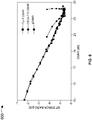
- Figure 4 illustrates a graph 400 depicting OSNR versus bit error ratio (BER). Figure 4 is similar to Figure 3 , but the x- and y-axes are swapped. In this way, the graph 400 may more readily depict an OSNR value dependent on the bit error ratio in a direct setup.
- an ITU-T OSNR may show an incorrect OSNR value at high launchpowers because of disobeying the intra-channel non-linear noise contributions.
- Figure 5 illustrates a graph 500 depicting OSNR versus launchpower in a setup with 65km single-mode optical fiber (SMF), according to an example. Whereas the spectral correlation of the OSCA may be directly influenced by non-linearities and will measure a correct gOSNR at least to a certain accuracy. This behavior may be demonstrated by looking also on the bit error ratio.
- Figure 6 illustrates a graph 600 depicting bit error ratio (BER) versus OSNR in a setup with 65km single-mode optical fiber (SMF), according to an example. As shown, increasing the launchpower may be be interpreted as moving to higher OSNR until the original OSNR is reached. Increasing the signal power to even higher levels may be apparently uncritical when only taking the ITU-T method into account.
- BER bit error ratio
- Figure 7 illustrates a graph 700 depicting OSNR versus bit error ratio (BER) in a setup with 65km single-mode optical fiber (SMF), according to an example.
- BER bit error ratio
- SMF single-mode optical fiber
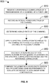
- Figure 8 illustrates a flow chart of a method 800 for performing linear and non-linear transmission perturbations measurements in optical transmission systems, according to an example.
- the method 800 is provided by way of example, as there may be a variety of ways to carry out the method described herein. Although the method 800 is primarily described as being performed by the system 100 of Figure 1 , respectively, the method 800 may be executed or otherwise performed by one or more processing components of another system or a combination of systems. Each block shown in Figure 8 may further represent one or more processes, methods, or subroutines, and one or more of the blocks may include machine readable instructions stored on a non-transitory computer readable medium and executed by a processor or other type of processing circuit to perform one or more operations described herein.
- the method may include, but not limited to, the following actions:
- systems and methods may also include or communicate with other components not shown.
- these may include external processors, counters, analyzers, computing devices, and other measuring devices or systems.
- This may also include middleware (not shown) as well.
- the middleware may include software hosted by one or more servers or devices.
- some of the middleware or servers may or may not be needed to achieve functionality.
- Other types of servers, middleware, systems, platforms, and applications not shown may also be provided at the back-end to facilitate the features and functionalities of the testing and measurement system.
- single components may be provided as multiple components, and vice versa, to perform the functions and features described herein. It should be appreciated that the components of the system described herein may operate in partial or full capacity, or it may be removed entirely. It should also be appreciated that analytics and processing techniques described herein with respect to the systems and methods, for example, may also be performed partially or in full by other various components of the overall system.
- data stores may also be provided to the apparatuses, systems, and methods described herein, and may include volatile and/or nonvolatile data storage that may store data and software or firmware including machine-readable instructions.
- the software or firmware may include subroutines or applications that perform the functions of the systems described herein and/or run one or more application that utilize data from these systems or other communicatively coupled system.
- the various components, circuits, elements, components, and interfaces may be any number of mechanical, electrical, hardware, network, or software components, circuits, elements, and interfaces that serves to facilitate communication, exchange, and analysis data between any number of or combination of equipment, protocol layers, or applications.
- the components described herein may each include a network or communication interface to communicate with other servers, devices, components or network elements via a network or other communication protocol.
- examples are directed to test and measurement systems for measuring linear and non-linear transmission perturbations in optical transmission systems
- the systems and methods described herein may also be used in other various systems and other implementations.
- the systems and methods may be used for spectral correlation in determining non-linear noise contributions and hence measuring generalized OSNR.
- the systems and methods described herein may also provide in-service opportunity to directly measure gOSNR on active links.
- the techniques described herein may be used in not only in common test and measurement systems but also in highly non-linear regimes whereas common OSA-devices may fail due to incompatibility.
Landscapes
- Physics & Mathematics (AREA)
- Engineering & Computer Science (AREA)
- Computer Networks & Wireless Communication (AREA)
- Signal Processing (AREA)
- Electromagnetism (AREA)
- Nonlinear Science (AREA)
- Optical Communication System (AREA)
Abstract
Description
- This patent application is directed to optical test and measurement in telecommunication networks, and more specifically, to measuring linear and non-linear transmission perturbations in optical transmission systems.
- According to a first aspect, there is provided a test instrument, comprising: a processor; a memory, which when executed by the processor, measures non-linear noise at an optical transceiver, as follows: receive a reference correlation of a transmission of a channel of a fiber link; record an optical power spectrum of the channel; determine a baud rate of the channel; and apply a spectral correlation technique to the channel with a multiple baud rate distance in frequency domain.
- The test instrument may further comprise: calculating a generalized optical signal-to-noise ratio (gOSNR) value based on the spectral correlation technique and the reference correlation; and comparing the gOSNR with wavelength division multiplexed (WDM) OSNR measurements to evaluate an amount of non-linear noise contributions.
- The reference correlation may be a value received from a third party system or a link operator.
- The optical power spectrum of the channel may be recorded from a point of interest on the fiber link.
- The baud rate of the channel may be determined based on at least one of a scan, estimate, or calculation.
- The baud rate of the channel may be 32GBaud for a 100Gbit PM-QPSK.
- The spectral correlation technique may comprise probing two frequency components of the channel.
- According to a second aspect, there is provided a method, comprising: receiving, by a processor, a reference correlation of a transmission of a channel of a fiber link; recording an optical power spectrum of the channel; determining a baud rate of the channel; and applying a spectral correlation technique to the channel with a multiple baud rate distance in frequency domain.
- The method may further comprise: calculating a generalized optical signal-to-noise ratio (gOSNR) value based on the spectral correlation technique and the reference correlation; and comparing the gOSNR with wavelength division multiplexed (WDM) OSNR measurements to evaluate an amount of non-linear noise contributions.
- The reference correlation may be a value received from a third party system or a link operator.
- The optical power spectrum of the channel may be recorded from a point of interest on the fiber link.
- The baud rate of the channel may be determined based on at least one of a scan, estimate, or calculation.
- The baud rate of the channel is 32GBaud for a 100Gbit PM-QPSK.
- The spectral correlation technique may comprise probing two frequency components of the channel.
- According to a third aspect, there is provided a non-transitory computer-readable storage medium having an executable stored thereon, which when executed instructs a processor to perform the following: receive a reference correlation of a transmission of a channel of a fiber link; record an optical power spectrum of the channel; determining a baud rate of the channel applying a spectral correlation technique to the channel with a multiple baud rate distance in frequency domain; calculating a generalized optical signal-to-noise ratio (gOSNR) value based on the spectral correlation technique and the reference correlation; and comparing the gOSNR with wavelength division multiplexed (WDM) OSNR measurements to evaluate an amount of non-linear noise contributions.
- The reference correlation may be a value received from a third party system or a link operator.
- The optical power spectrum of the channel may be recorded from a point of interest on the fiber link.
- The baud rate of the channel may be determined based on at least one of a scan, estimate, or calculation.
- The baud rate of the channel may be 32GBaud for a 100Gbit PM-QPSK.
- The spectral correlation technique may comprise probing two frequency components of the channel.
- According to a fourth aspect, there is provided a non-transitory computer-readable storage medium having an executable stored thereon, which when executed instructs a processor to perform the method of the second aspect.
- Features of the present disclosure are illustrated by way of example and not limited in the following Figure(s), in which like numerals indicate like elements, in which:
-
Figure 1 illustrates a system for measuring linear and non-linear transmission perturbations in an exemplary setup with either a 65km single-mode optical fiber (SMF) link or a direct connection, according to an example; -
Figure 2 illustrates a graph depicting optical signal-to-noise ratio (OSNR) versus launchpower in a direct setup, according to an example; -
Figure 3 illustrates a graph depicting bit error ratio (BER) versus optical signal-to-noise ratio (OSNR) in a direct setup, according to an example; -
Figure 4 illustrates a graph depicting optical signal-to-noise ratio (OSNR) versus bit error ratio (BER) in a direct setup, according to an example; -
Figure 5 illustrates a graph depicting optical signal-to-noise ratio (OSNR) versus launchpower in a setup with 65km single-mode optical fiber (SMF), according to an example; -
Figure 6 illustrates a graph depicting bit error ratio (BER) versus optical signal-to-noise ratio (OSNR) in a setup with 65km single-mode optical fiber (SMF), according to an example. -
Figure 7 illustrates a graph depicting optical signal-to-noise ratio (OSNR) versus bit error ration (BER) in a setup with 65km single-mode optical fiber (SMF), according to an example; and -
Figure 8 illustrates a flow chart of a method for performing linear and non-linear transmission perturbations measurements in optical transmission systems, according to an example. - For simplicity and illustrative purposes, the present disclosure is described by referring mainly to examples and embodiments thereof. In the following description, numerous specific details are set forth in order to provide a thorough understanding of the present disclosure. It will be readily apparent, however, that the present disclosure may be practiced without limitation to these specific details. In other instances, some methods and structures readily understood by one of ordinary skill in the art have not been described in detail so as not to unnecessarily obscure the present disclosure. As used herein, the terms "a" and "an" are intended to denote at least one of a particular element, the term "includes" means includes but not limited to, the term "including" means including but not limited to, and the term "based on" means based at least in part on.
- The quality of modulated optical signals transmitted in long-distance fiber-optic communications is frequently characterized by optical signal-to-noise ratio (OSNR), which may define a ratio of the total optical power of digital information signal to optical noise added to the signal by optical amplifiers. In communications with only a few widely-spaced wavelength-multiplexed signals, OSNR may be readily determined by spectral analysis of a transmitted noisy signal and the optical noise floor on either side of the signal spectrum. In modern optical communication systems with dense wavelength-division multiplexing (DWDM), various transmitted optical signals are closely spaced in optical frequency, so that it becomes difficult to measure optical noise floor between adjacent signal spectra. This may be of particular concern for communication systems transmitting optical signals at bit rates of 100 Gb/s over 50-GHz wide wavelength channels. In these systems, measuring the optical noise floor within the spectral bandwidth of the signal may be needed to determine the signal's OSNR. Such measurements may be commonly referred to as in-band OSNR. Furthermore, it may be frequently required that these in-band OSNR measurements are performed while the communication is in service, i.e., that the noise floor within the signal's bandwidth is determined while the optical information signal is transmitted. There may be many challenges posed by these requirements.
- One way that these challenges may be addressed is via spectral correlation techniques, as described in
U.S. Patent No. 9,825,698 to Heismann - With telecommunication providers looking to drive network performance as bandwidth demands from customers continue to increase, many approaches have been developed to help to overcome any such bandwidth shortfall. For instance, with Nyquist-shaped signals, it may be possible to go to higher modulations-formats, keeping bandwidth boundary conditions and by simultaneously increasing the power levels, to transmit signals even over longer distances. However, it should be appreciated that non-linear distortions have been identified as one of the main limitations in long haul coherent optical systems leading to additional system restrictions and problems.
- To address these and other similar technical problems, knowledge about the amount of each distortion may be acquired and used to tune system performance to an optimum where the trade-off between performance and stability can be met. While linear noise may be directly measured and expressed as OSNR using an optical spectrum analyzer (OSA), there is currently no reliable system or method to directly assess non-linear signal degradations or perturbations in optical transmission systems.
- An optical spectrum analyzer (OSA) may employ a spectral correlation technique, for example and as described above, on polarization multiplexed signals for calculating the OSNR from a carrier in a coherent system. The spectral correlation technique used may be separated by a baud rate in the frequency domain. If the power-levels reach the non-linear threshold of a fiberspan additional physical effects may arise and may need to be considered when characterizing OSNR because the noise-floor may consist of extra contributions coming from non-linear perturbations, as shown by the following expressions:


- The nature of non-linear effects may appear random but may generally follow a Gaussian distribution. This may explain why non-linear noise components are not typically correlated to each other. Thus, by probing the two signal frequency components of the spectrum, a test instrument may instantly understand or measure the underlying noise components at these frequencies as well. When the uncorrelated noise components increase due to non-linearities, the correlation of the signal components may be immediately disturbed and decreased. Decreasing signal correlation may imply causally determined increasing noise components. This relationship may be directly measured using the techniques described herein.
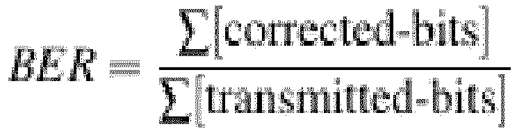
- In some examples, a bit error tester may be used as a reference. In particular, this may be achieved by looking at the bit error ratio (BER) and by counting transmitted bytes encrypted with a forward error correction (FEC) algorithm or technique divided by the amount of bytes which had to be corrected at the receiver side, as shown in the expression below:
-
Figure 1 illustrates asystem 100 for measuring linear and non-linear transmission perturbations in an exemplary setup, e.g., with either a 65km single-mode optical fiber (SMF) link or a direct connection, according to an example. As shown, the generated traffic with forward error correction (FEC) may encounter a first amplification stage, which may be used to set a launchpower and may boost the signal, e.g., to a max 30dBm or other level. After this first booster (e.g., Erbium-doped fiber amplifier (EDFA)), a part of the signal may be coupled out to monitor the launchpower with an OSA. The signal may then be routed either through a 65km fiber link or bypassed with an optical power level attenuator (OLA), which may be set up to exactly the same (or similar) insertion loss as the link. - In the next step, a final amplification stage may be introduced for pre-amplifying the signal right before an optical spectrum and correlation analyzer (OSCA) in order to maintain a constant power level with another OLA at the receiver side. At this point, the signal may be evenly split into two parts, one going directly to the OSCA and the other returning to the ONT running through an optical filter to avoid cross-talk finally reaching the bit error rate tester. All or most of the data from OSA, OSCA, and/or ONT may be recorded, stored, and used for analysis. It should be appreciated that the OSNR of the signal may be set to 24dB (or other level) and the reference correlation may be obtained at the transmitter side (or other location). Other various examples or alternatives may also be provided.
-
Figure 2 illustrates agraph 200 depicting OSNR versus launchpower in a direct setup, according to an example. In some examples, the measurement without the 65km SMF link may be considered to be a reference. The OSNR versus launchpower may be recorded as well as the bit error ratio versus OSNR, as shown. It should be appreciated that a compliant OSNR measurement may be the same as or similar to the OSNR measured with the OSCA. In some examples, both curves may follow a true theoretical generalized OSNR (gOSNR) line because no non-linearities may be present respectively and the signal power threshold may not be met. -
Figure 3 illustrates agraph 300 depicting bit error ratio (BER) versus OSNR in a direct setup, according to an example. It should be appreciated that a straight line, as shown, may indicate that a lower OSNR corresponds to a higher bit error ratio and vice-versa.Figure 4 illustrates agraph 400 depicting OSNR versus bit error ratio (BER).Figure 4 is similar toFigure 3 , but the x- and y-axes are swapped. In this way, thegraph 400 may more readily depict an OSNR value dependent on the bit error ratio in a direct setup. - When the signal is travelling over longer distances at certain power-levels, there may be non-linear effects, similar to self-phase-modulation, cross-phase-modulation, or four-wave mixing, etc., that may interfere with original signal components. This may lead to a degradation of the OSNR and as well as in the bit error ratio (BER). It should be appreciated that if the power-levels rise over a certain threshold value and the interaction time (fiber length) is long enough, the non-linearities may contribute to common noise-floor inside the channel, modifying the original OSNR. Standard techniques, which may not be sensitive to inter-channel effects, cannot generally recognize the enlarged noise-floor and therefore the lower gOSNR.
- In other words, an ITU-T OSNR may show an incorrect OSNR value at high launchpowers because of disobeying the intra-channel non-linear noise contributions.
Figure 5 , for example, illustrates agraph 500 depicting OSNR versus launchpower in a setup with 65km single-mode optical fiber (SMF), according to an example. Whereas the spectral correlation of the OSCA may be directly influenced by non-linearities and will measure a correct gOSNR at least to a certain accuracy. This behavior may be demonstrated by looking also on the bit error ratio. For example,Figure 6 illustrates agraph 600 depicting bit error ratio (BER) versus OSNR in a setup with 65km single-mode optical fiber (SMF), according to an example. As shown, increasing the launchpower may be be interpreted as moving to higher OSNR until the original OSNR is reached. Increasing the signal power to even higher levels may be apparently uncritical when only taking the ITU-T method into account. - It should be appreciated that exceeding the threshold power level may lead to a reversal in OSNR and simultaneously decreasing the bit-error ratio. However, this may be for generalized OSNR, including all kind of noise contributions, which may be different to the ITU-T measured OSNR but is directly accessible with the correlation method included in the OSCA. Other various examples or alternatives may also be provided.
-
Figure 7 illustrates agraph 700 depicting OSNR versus bit error ratio (BER) in a setup with 65km single-mode optical fiber (SMF), according to an example. By swapping x- and y-axes, an OSNR value dependent on the bit error ratio may be achieved, as shown, which may be misleading using a normal optical spectrum analyzer in the non-linear regime. -
Figure 8 illustrates a flow chart of amethod 800 for performing linear and non-linear transmission perturbations measurements in optical transmission systems, according to an example. Themethod 800 is provided by way of example, as there may be a variety of ways to carry out the method described herein. Although themethod 800 is primarily described as being performed by thesystem 100 ofFigure 1 , respectively, themethod 800 may be executed or otherwise performed by one or more processing components of another system or a combination of systems. Each block shown inFigure 8 may further represent one or more processes, methods, or subroutines, and one or more of the blocks may include machine readable instructions stored on a non-transitory computer readable medium and executed by a processor or other type of processing circuit to perform one or more operations described herein. - The method may include, but not limited to, the following actions:
- Measure or receive, at 810, a reference correlation of a transmission of a channel of a fiber link (or get the value from vendor (third party system) or link operator);
- Record, at 820, an optical power spectrum of the channel under investigation at point of interest on the fiber link;
- Determine/guess/scan, at 830, a baud rate of the channel (e.g., 32GBaud for 100Gbit PM-QPSK);
- Apply, at 840, a spectral correlation technique. This may be achieved, for example, by probing two frequency components of the channel or by applying a spectral correlation technique to the channel with a multiple baud rate distance in frequency domain (e.g., 32GHz ⇔ 32GBaud);
- Calculate, at 850, a gOSNR value based on the spectral correlation technique and the reference correlation; and
- Compare, at 860, the gOSNR with wavelength division multiplexed (WDM) OSNR measurements to evaluate an amount of non-linear noise contributions.
- While examples described herein are directed to configurations as shown, it should be appreciated that any of the components described herein may be altered, changed, replaced, or modified, in size, shape, and numbers, or material, depending on application or use case, and adjusted for desired measurements of linear and non-linear transmission perturbations in optical transmission systems.
- It should also be appreciated that the systems and methods, as described herein, may also include or communicate with other components not shown. For example, these may include external processors, counters, analyzers, computing devices, and other measuring devices or systems. This may also include middleware (not shown) as well. The middleware may include software hosted by one or more servers or devices. Furthermore, it should be appreciated that some of the middleware or servers may or may not be needed to achieve functionality. Other types of servers, middleware, systems, platforms, and applications not shown may also be provided at the back-end to facilitate the features and functionalities of the testing and measurement system.
- Moreover, single components may be provided as multiple components, and vice versa, to perform the functions and features described herein. It should be appreciated that the components of the system described herein may operate in partial or full capacity, or it may be removed entirely. It should also be appreciated that analytics and processing techniques described herein with respect to the systems and methods, for example, may also be performed partially or in full by other various components of the overall system.
- It should be appreciated that data stores may also be provided to the apparatuses, systems, and methods described herein, and may include volatile and/or nonvolatile data storage that may store data and software or firmware including machine-readable instructions. The software or firmware may include subroutines or applications that perform the functions of the systems described herein and/or run one or more application that utilize data from these systems or other communicatively coupled system.
- The various components, circuits, elements, components, and interfaces, may be any number of mechanical, electrical, hardware, network, or software components, circuits, elements, and interfaces that serves to facilitate communication, exchange, and analysis data between any number of or combination of equipment, protocol layers, or applications. For example, the components described herein may each include a network or communication interface to communicate with other servers, devices, components or network elements via a network or other communication protocol.
- Although examples are directed to test and measurement systems for measuring linear and non-linear transmission perturbations in optical transmission systems, it should be appreciated that that the systems and methods described herein may also be used in other various systems and other implementations. For example, the systems and methods may be used for spectral correlation in determining non-linear noise contributions and hence measuring generalized OSNR. The systems and methods described herein may also provide in-service opportunity to directly measure gOSNR on active links. Moreover, the techniques described herein may be used in not only in common test and measurement systems but also in highly non-linear regimes whereas common OSA-devices may fail due to incompatibility.
- What has been described and illustrated herein are examples of the disclosure along with some variations. The terms, descriptions, and figures used herein are set forth by way of illustration only and are not meant as limitations. Many variations are possible within the scope of the disclosure, which is intended to be defined by the following claims-and their equivalents-in which all terms are meant in their broadest reasonable sense unless otherwise indicated.
Claims (15)
- A test instrument, comprising:a processor;a memory, which when executed by the processor, measures non-linear noise at an optical transceiver, as follows:receive a reference correlation of a transmission of a channel of a fiber link;record an optical power spectrum of the channel;determine a baud rate of the channel; andapply a spectral correlation technique to the channel with a multiple baud rate distance in frequency domain.
- The test instrument of claim 1, further comprising:calculating a generalized optical signal-to-noise ratio (gOSNR) value based on the spectral correlation technique and the reference correlation; andcomparing the gOSNR with wavelength division multiplexed (WDM) OSNR measurements to evaluate an amount of non-linear noise contributions.
- The test instrument of claim 1, wherein the reference correlation is a value received from a third party system or a link operator.
- The test instrument of claim 1, wherein the optical power spectrum of the channel is recorded from a point of interest on the fiber link.
- The test instrument of claim 1, wherein the baud rate of the channel is determined based on at least one of a scan, estimate, or calculation.
- The test instrument of claim 1, wherein the baud rate of the channel is 32GBaud for a 100Gbit PM-QPSK.
- The test instrument of claim 1, wherein the spectral correlation technique comprises probing two frequency components of the channel.
- A method, comprising:receiving, by a processor, a reference correlation of a transmission of a channel of a fiber link;recording an optical power spectrum of the channel;determining a baud rate of the channel; andapplying a spectral correlation technique to the channel with a multiple baud rate distance in frequency domain.
- The method of claim 8, further comprising:calculating a generalized optical signal-to-noise ratio (gOSNR) value based on the spectral correlation technique and the reference correlation; andcomparing the gOSNR with wavelength division multiplexed (WDM) OSNR measurements to evaluate an amount of non-linear noise contributions.
- The method of claim 8, wherein the reference correlation is a value received from a third party system or a link operator.
- The method of claim 8, wherein the optical power spectrum of the channel is recorded from a point of interest on the fiber link.
- The method of claim 8, wherein the baud rate of the channel is determined based on at least one of a scan, estimate, or calculation.
- The method of claim 8, wherein the baud rate of the channel is 32GBaud for a 100Gbit PM-QPSK.
- The method of claim 8, wherein the spectral correlation technique comprises probing two frequency components of the channel.
- A non-transitory computer-readable storage medium having an executable stored thereon, which when executed instructs a processor to perform the method of any of claims 8-14.
Applications Claiming Priority (2)
| Application Number | Priority Date | Filing Date | Title |
|---|---|---|---|
| US201962867635P | 2019-06-27 | 2019-06-27 | |
| US201962869896P | 2019-07-02 | 2019-07-02 |
Publications (2)
| Publication Number | Publication Date |
|---|---|
| EP3758258A1 true EP3758258A1 (en) | 2020-12-30 |
| EP3758258B1 EP3758258B1 (en) | 2023-04-12 |
Family
ID=71266478
Family Applications (1)
| Application Number | Title | Priority Date | Filing Date |
|---|---|---|---|
| EP20182827.4A Active EP3758258B1 (en) | 2019-06-27 | 2020-06-29 | Measuring linear and non-linear transmission perturbations in optical transmission systems |
Country Status (2)
| Country | Link |
|---|---|
| US (1) | US11309960B2 (en) |
| EP (1) | EP3758258B1 (en) |
Families Citing this family (4)
| Publication number | Priority date | Publication date | Assignee | Title |
|---|---|---|---|---|
| US11595125B2 (en) * | 2020-02-28 | 2023-02-28 | Exfo Inc. | Transceiver agnostic GOSNR measurement |
| US11716138B2 (en) * | 2021-10-18 | 2023-08-01 | Huawei Technologies Co., Ltd. | Systems and methods for monitoring generalized optical signal-to-noise ratio |
| CN117176246B (en) * | 2022-09-27 | 2024-06-18 | 中国移动通信集团设计院有限公司 | Method, device, equipment and computer storage medium for determining performance index |
| US12476712B2 (en) * | 2023-09-08 | 2025-11-18 | Huawei Technologies Co., Ltd. | Method and device for monitoring generalized optical signal-to-noise ratio, coherent receiver and network apparatus |
Citations (3)
| Publication number | Priority date | Publication date | Assignee | Title |
|---|---|---|---|---|
| EP2569879A1 (en) * | 2011-07-27 | 2013-03-20 | Huawei Technologies Co., Ltd. | Method and apparatus for determining an optical signal-to-noise ratio (osnr) penalty |
| US9825698B2 (en) | 2014-12-09 | 2017-11-21 | Viavi Solutions Inc. | Determining in-band optical signal-to-noise ratio in polarization-multiplexed optical signals using signal correlations |
| WO2018197975A1 (en) * | 2017-04-26 | 2018-11-01 | Exfo Inc. | Noise-free measurement of the spectral shape of a modulated signal using spectral correlation |
Family Cites Families (18)
| Publication number | Priority date | Publication date | Assignee | Title |
|---|---|---|---|---|
| US7542674B1 (en) * | 2001-05-24 | 2009-06-02 | Cisco Technology, Inc. | Optical link performance monitoring |
| US8095342B2 (en) * | 2008-04-07 | 2012-01-10 | Ciena Corporation | Systems and methods for highly efficient bit error rate modeling in quasi-linear communication networks |
| EP2486678B1 (en) * | 2010-02-15 | 2018-08-15 | Exfo Inc. | Reference-based in-band osnr measurement on polarization-multiplexed signals |
| ES2621845T3 (en) * | 2012-06-28 | 2017-07-05 | Huawei Technologies Co., Ltd. | Method and device to calculate the reduction of non-linear transmission of fiber optic link |
| US9641252B2 (en) * | 2012-08-03 | 2017-05-02 | Telefonaktiebolaget Lm Ericsson (Publ) | Method of optimizing optical signal quality in an optical communications link, optical network element and optical communications link |
| US9859976B2 (en) * | 2014-03-03 | 2018-01-02 | Eci Telecom Ltd. | OSNR margin monitoring for optical coherent signals |
| US9344190B2 (en) * | 2014-05-14 | 2016-05-17 | Fujitsu Limited | Flexible placement of spectral inverters in optical networks |
| JP6666645B2 (en) * | 2014-05-16 | 2020-03-18 | 富士通株式会社 | Apparatus and method for measuring signal light quality |
| EP3018839B1 (en) * | 2014-11-05 | 2020-01-15 | EXFO Inc. | In-band noise and/or spectral deformation measurement on polarization-multiplexed signals |
| JP6380136B2 (en) * | 2015-01-30 | 2018-08-29 | 富士通株式会社 | Estimation apparatus and estimation method |
| US10567075B2 (en) * | 2015-05-07 | 2020-02-18 | Centre For Development Telematics | GIS based centralized fiber fault localization system |
| CN106559133B (en) * | 2015-09-28 | 2020-02-14 | 华为技术有限公司 | Optical signal detection method and network device thereof |
| JP6638535B2 (en) * | 2016-04-19 | 2020-01-29 | 富士通株式会社 | Network control device and transmission quality margin calculation method |
| US10211917B1 (en) * | 2016-06-29 | 2019-02-19 | Juniper Networks, Inc. | Methods and apparatus for predicting and monitoring performance of a coherent optical transceiver |
| US10090920B1 (en) * | 2017-03-17 | 2018-10-02 | Ciena Corporation | Fiber kerr nonlinear noise estimation |
| CN110971295B (en) * | 2018-09-28 | 2023-01-17 | 富士通株式会社 | Fiber optic nonlinear noise monitoring device and optical receiver |
| US10887009B2 (en) * | 2018-10-08 | 2021-01-05 | Nec Corporation | G-OSNR estimation on dynamic PS-QAM channels using hybrid neural networks |
| US10965371B2 (en) * | 2019-04-12 | 2021-03-30 | Huawei Technologies Co., Ltd. | Optical performance monitoring based on fast bit error rate (BER) statistics |
-
2020
- 2020-06-29 EP EP20182827.4A patent/EP3758258B1/en active Active
- 2020-06-29 US US16/915,653 patent/US11309960B2/en active Active
Patent Citations (3)
| Publication number | Priority date | Publication date | Assignee | Title |
|---|---|---|---|---|
| EP2569879A1 (en) * | 2011-07-27 | 2013-03-20 | Huawei Technologies Co., Ltd. | Method and apparatus for determining an optical signal-to-noise ratio (osnr) penalty |
| US9825698B2 (en) | 2014-12-09 | 2017-11-21 | Viavi Solutions Inc. | Determining in-band optical signal-to-noise ratio in polarization-multiplexed optical signals using signal correlations |
| WO2018197975A1 (en) * | 2017-04-26 | 2018-11-01 | Exfo Inc. | Noise-free measurement of the spectral shape of a modulated signal using spectral correlation |
Non-Patent Citations (2)
| Title |
|---|
| PETER WINTERLING: "Spektral korrelieren - Optische Spektrumanalyse an kohärenten Übertragungssystemen von 100-Gigabit-Ethernet und höher", NET ZEITSCHRIFT FÜR KOMMUNIKATIONSMANAGEMENT, no. 3, 1 March 2019 (2019-03-01), DE, pages 26 - 29, XP055660285, ISSN: 0947-4765 * |
| WOLFGANG GRUPP ET AL: "In-band OSNR Measurement based on Spectral Correlation", 3 May 2010 (2010-05-03), XP055252440, Retrieved from the Internet <URL:http://ieeexplore.ieee.org/ielx5/5755475/5755476/05755971.pdf?tp=&arnumber=5755971&isnumber=5755476> [retrieved on 20160223] * |
Also Published As
| Publication number | Publication date |
|---|---|
| EP3758258B1 (en) | 2023-04-12 |
| US11309960B2 (en) | 2022-04-19 |
| US20200412448A1 (en) | 2020-12-31 |
Similar Documents
| Publication | Publication Date | Title |
|---|---|---|
| EP3758258B1 (en) | Measuring linear and non-linear transmission perturbations in optical transmission systems | |
| JP4782644B2 (en) | System and method for monitoring an optical communication system | |
| US10411796B1 (en) | Optical fiber characterization measurement systems and methods | |
| US8655170B2 (en) | OSNR monitor device and OSNR measurement device | |
| US11139633B2 (en) | In-situ fiber characterization using nonlinear skirt measurement | |
| US6907197B2 (en) | Method and apparatus for measuring and estimating optical signal to noise ratio in photonic networks | |
| US7912370B2 (en) | Optical power measurement apparatus and optical power measurement method | |
| RU2677263C2 (en) | Method of monitoring of system margin to optical signal to noise ratio and coherent receiving device | |
| US9954610B2 (en) | In-band noise determination on optical communication signals | |
| CN105577271B (en) | In-band noise and/or spectral distortion measurement on polarization multiplexed signals | |
| JPH118590A (en) | Optical transmission system and monitoring control method therefor | |
| CN112292819B (en) | Automated measurement of transponder noise performance | |
| WO2012119364A1 (en) | Method and apparatus for determining an optical signal-to-noise ratio (OSNR) penalty | |
| US11349564B2 (en) | Crosstalk estimation system | |
| Sena et al. | Link tomography for amplifier gain profile estimation and failure detection in C+ L-band open line systems | |
| WO2025051202A1 (en) | Method and device for monitoring generalized optical signal-to-noise ratio, coherent receiver and network apparatus | |
| US7457032B2 (en) | Arrangement, system, and method for accurate power measurements using an optical performance monitor (OPM) | |
| JP2008521304A (en) | Optical signal monitoring apparatus and method | |
| US12580649B2 (en) | Optical signal-to-noise ratio measurement method and apparatus, and computer storage medium | |
| Anderson et al. | Robust, low cost, in-band optical signal to noise monitoring using polarization diversity | |
| JP4867718B2 (en) | Optical signal to noise ratio measuring method in optical communication system and optical signal to noise ratio measuring apparatus using the measuring method | |
| Searcy et al. | Experimental validation of GOSNR estimation using polarization-resolved optical spectrum analysis on metro and long-haul WDM links | |
| US20110311236A1 (en) | Optical amplifier, control method therefor, and optical transmission system | |
| Çerri | A Study on the Optical Signal Noise Ratio (OSNR): Report on the Performance of DWDM Systems |
Legal Events
| Date | Code | Title | Description |
|---|---|---|---|
| PUAI | Public reference made under article 153(3) epc to a published international application that has entered the european phase |
Free format text: ORIGINAL CODE: 0009012 |
|
| STAA | Information on the status of an ep patent application or granted ep patent |
Free format text: STATUS: THE APPLICATION HAS BEEN PUBLISHED |
|
| AK | Designated contracting states |
Kind code of ref document: A1 Designated state(s): AL AT BE BG CH CY CZ DE DK EE ES FI FR GB GR HR HU IE IS IT LI LT LU LV MC MK MT NL NO PL PT RO RS SE SI SK SM TR |
|
| AX | Request for extension of the european patent |
Extension state: BA ME |
|
| STAA | Information on the status of an ep patent application or granted ep patent |
Free format text: STATUS: REQUEST FOR EXAMINATION WAS MADE |
|
| 17P | Request for examination filed |
Effective date: 20210621 |
|
| RBV | Designated contracting states (corrected) |
Designated state(s): AL AT BE BG CH CY CZ DE DK EE ES FI FR GB GR HR HU IE IS IT LI LT LU LV MC MK MT NL NO PL PT RO RS SE SI SK SM TR |
|
| RAP3 | Party data changed (applicant data changed or rights of an application transferred) |
Owner name: VIAVI SOLUTIONS INC. |
|
| GRAP | Despatch of communication of intention to grant a patent |
Free format text: ORIGINAL CODE: EPIDOSNIGR1 |
|
| STAA | Information on the status of an ep patent application or granted ep patent |
Free format text: STATUS: GRANT OF PATENT IS INTENDED |
|
| INTG | Intention to grant announced |
Effective date: 20221123 |
|
| GRAS | Grant fee paid |
Free format text: ORIGINAL CODE: EPIDOSNIGR3 |
|
| GRAA | (expected) grant |
Free format text: ORIGINAL CODE: 0009210 |
|
| STAA | Information on the status of an ep patent application or granted ep patent |
Free format text: STATUS: THE PATENT HAS BEEN GRANTED |
|
| AK | Designated contracting states |
Kind code of ref document: B1 Designated state(s): AL AT BE BG CH CY CZ DE DK EE ES FI FR GB GR HR HU IE IS IT LI LT LU LV MC MK MT NL NO PL PT RO RS SE SI SK SM TR |
|
| REG | Reference to a national code |
Ref country code: GB Ref legal event code: FG4D |
|
| REG | Reference to a national code |
Ref country code: CH Ref legal event code: EP |
|
| REG | Reference to a national code |
Ref country code: DE Ref legal event code: R096 Ref document number: 602020009624 Country of ref document: DE |
|
| REG | Reference to a national code |
Ref country code: IE Ref legal event code: FG4D |
|
| REG | Reference to a national code |
Ref country code: AT Ref legal event code: REF Ref document number: 1560367 Country of ref document: AT Kind code of ref document: T Effective date: 20230515 |
|
| P01 | Opt-out of the competence of the unified patent court (upc) registered |
Effective date: 20230530 |
|
| REG | Reference to a national code |
Ref country code: LT Ref legal event code: MG9D |
|
| REG | Reference to a national code |
Ref country code: NL Ref legal event code: MP Effective date: 20230412 |
|
| REG | Reference to a national code |
Ref country code: AT Ref legal event code: MK05 Ref document number: 1560367 Country of ref document: AT Kind code of ref document: T Effective date: 20230412 |
|
| PG25 | Lapsed in a contracting state [announced via postgrant information from national office to epo] |
Ref country code: NL Free format text: LAPSE BECAUSE OF FAILURE TO SUBMIT A TRANSLATION OF THE DESCRIPTION OR TO PAY THE FEE WITHIN THE PRESCRIBED TIME-LIMIT Effective date: 20230412 |
|
| PG25 | Lapsed in a contracting state [announced via postgrant information from national office to epo] |
Ref country code: SE Free format text: LAPSE BECAUSE OF FAILURE TO SUBMIT A TRANSLATION OF THE DESCRIPTION OR TO PAY THE FEE WITHIN THE PRESCRIBED TIME-LIMIT Effective date: 20230412 Ref country code: PT Free format text: LAPSE BECAUSE OF FAILURE TO SUBMIT A TRANSLATION OF THE DESCRIPTION OR TO PAY THE FEE WITHIN THE PRESCRIBED TIME-LIMIT Effective date: 20230814 Ref country code: NO Free format text: LAPSE BECAUSE OF FAILURE TO SUBMIT A TRANSLATION OF THE DESCRIPTION OR TO PAY THE FEE WITHIN THE PRESCRIBED TIME-LIMIT Effective date: 20230712 Ref country code: ES Free format text: LAPSE BECAUSE OF FAILURE TO SUBMIT A TRANSLATION OF THE DESCRIPTION OR TO PAY THE FEE WITHIN THE PRESCRIBED TIME-LIMIT Effective date: 20230412 Ref country code: AT Free format text: LAPSE BECAUSE OF FAILURE TO SUBMIT A TRANSLATION OF THE DESCRIPTION OR TO PAY THE FEE WITHIN THE PRESCRIBED TIME-LIMIT Effective date: 20230412 |
|
| PG25 | Lapsed in a contracting state [announced via postgrant information from national office to epo] |
Ref country code: RS Free format text: LAPSE BECAUSE OF FAILURE TO SUBMIT A TRANSLATION OF THE DESCRIPTION OR TO PAY THE FEE WITHIN THE PRESCRIBED TIME-LIMIT Effective date: 20230412 Ref country code: PL Free format text: LAPSE BECAUSE OF FAILURE TO SUBMIT A TRANSLATION OF THE DESCRIPTION OR TO PAY THE FEE WITHIN THE PRESCRIBED TIME-LIMIT Effective date: 20230412 Ref country code: LV Free format text: LAPSE BECAUSE OF FAILURE TO SUBMIT A TRANSLATION OF THE DESCRIPTION OR TO PAY THE FEE WITHIN THE PRESCRIBED TIME-LIMIT Effective date: 20230412 Ref country code: LT Free format text: LAPSE BECAUSE OF FAILURE TO SUBMIT A TRANSLATION OF THE DESCRIPTION OR TO PAY THE FEE WITHIN THE PRESCRIBED TIME-LIMIT Effective date: 20230412 Ref country code: IS Free format text: LAPSE BECAUSE OF FAILURE TO SUBMIT A TRANSLATION OF THE DESCRIPTION OR TO PAY THE FEE WITHIN THE PRESCRIBED TIME-LIMIT Effective date: 20230812 Ref country code: HR Free format text: LAPSE BECAUSE OF FAILURE TO SUBMIT A TRANSLATION OF THE DESCRIPTION OR TO PAY THE FEE WITHIN THE PRESCRIBED TIME-LIMIT Effective date: 20230412 Ref country code: GR Free format text: LAPSE BECAUSE OF FAILURE TO SUBMIT A TRANSLATION OF THE DESCRIPTION OR TO PAY THE FEE WITHIN THE PRESCRIBED TIME-LIMIT Effective date: 20230713 Ref country code: AL Free format text: LAPSE BECAUSE OF FAILURE TO SUBMIT A TRANSLATION OF THE DESCRIPTION OR TO PAY THE FEE WITHIN THE PRESCRIBED TIME-LIMIT Effective date: 20230412 |
|
| PG25 | Lapsed in a contracting state [announced via postgrant information from national office to epo] |
Ref country code: FI Free format text: LAPSE BECAUSE OF FAILURE TO SUBMIT A TRANSLATION OF THE DESCRIPTION OR TO PAY THE FEE WITHIN THE PRESCRIBED TIME-LIMIT Effective date: 20230412 |
|
| REG | Reference to a national code |
Ref country code: DE Ref legal event code: R097 Ref document number: 602020009624 Country of ref document: DE |
|
| PG25 | Lapsed in a contracting state [announced via postgrant information from national office to epo] |
Ref country code: SK Free format text: LAPSE BECAUSE OF FAILURE TO SUBMIT A TRANSLATION OF THE DESCRIPTION OR TO PAY THE FEE WITHIN THE PRESCRIBED TIME-LIMIT Effective date: 20230412 |
|
| PG25 | Lapsed in a contracting state [announced via postgrant information from national office to epo] |
Ref country code: MC Free format text: LAPSE BECAUSE OF FAILURE TO SUBMIT A TRANSLATION OF THE DESCRIPTION OR TO PAY THE FEE WITHIN THE PRESCRIBED TIME-LIMIT Effective date: 20230412 |
|
| PG25 | Lapsed in a contracting state [announced via postgrant information from national office to epo] |
Ref country code: SM Free format text: LAPSE BECAUSE OF FAILURE TO SUBMIT A TRANSLATION OF THE DESCRIPTION OR TO PAY THE FEE WITHIN THE PRESCRIBED TIME-LIMIT Effective date: 20230412 Ref country code: SK Free format text: LAPSE BECAUSE OF FAILURE TO SUBMIT A TRANSLATION OF THE DESCRIPTION OR TO PAY THE FEE WITHIN THE PRESCRIBED TIME-LIMIT Effective date: 20230412 Ref country code: RO Free format text: LAPSE BECAUSE OF FAILURE TO SUBMIT A TRANSLATION OF THE DESCRIPTION OR TO PAY THE FEE WITHIN THE PRESCRIBED TIME-LIMIT Effective date: 20230412 Ref country code: MC Free format text: LAPSE BECAUSE OF FAILURE TO SUBMIT A TRANSLATION OF THE DESCRIPTION OR TO PAY THE FEE WITHIN THE PRESCRIBED TIME-LIMIT Effective date: 20230412 Ref country code: EE Free format text: LAPSE BECAUSE OF FAILURE TO SUBMIT A TRANSLATION OF THE DESCRIPTION OR TO PAY THE FEE WITHIN THE PRESCRIBED TIME-LIMIT Effective date: 20230412 Ref country code: DK Free format text: LAPSE BECAUSE OF FAILURE TO SUBMIT A TRANSLATION OF THE DESCRIPTION OR TO PAY THE FEE WITHIN THE PRESCRIBED TIME-LIMIT Effective date: 20230412 Ref country code: CZ Free format text: LAPSE BECAUSE OF FAILURE TO SUBMIT A TRANSLATION OF THE DESCRIPTION OR TO PAY THE FEE WITHIN THE PRESCRIBED TIME-LIMIT Effective date: 20230412 |
|
| REG | Reference to a national code |
Ref country code: CH Ref legal event code: PL |
|
| PLBE | No opposition filed within time limit |
Free format text: ORIGINAL CODE: 0009261 |
|
| STAA | Information on the status of an ep patent application or granted ep patent |
Free format text: STATUS: NO OPPOSITION FILED WITHIN TIME LIMIT |
|
| REG | Reference to a national code |
Ref country code: BE Ref legal event code: MM Effective date: 20230630 |
|
| PG25 | Lapsed in a contracting state [announced via postgrant information from national office to epo] |
Ref country code: LU Free format text: LAPSE BECAUSE OF NON-PAYMENT OF DUE FEES Effective date: 20230629 |
|
| 26N | No opposition filed |
Effective date: 20240115 |
|
| REG | Reference to a national code |
Ref country code: IE Ref legal event code: MM4A |
|
| PG25 | Lapsed in a contracting state [announced via postgrant information from national office to epo] |
Ref country code: LU Free format text: LAPSE BECAUSE OF NON-PAYMENT OF DUE FEES Effective date: 20230629 |
|
| PG25 | Lapsed in a contracting state [announced via postgrant information from national office to epo] |
Ref country code: IE Free format text: LAPSE BECAUSE OF NON-PAYMENT OF DUE FEES Effective date: 20230629 |
|
| PG25 | Lapsed in a contracting state [announced via postgrant information from national office to epo] |
Ref country code: IE Free format text: LAPSE BECAUSE OF NON-PAYMENT OF DUE FEES Effective date: 20230629 Ref country code: CH Free format text: LAPSE BECAUSE OF NON-PAYMENT OF DUE FEES Effective date: 20230630 |
|
| PG25 | Lapsed in a contracting state [announced via postgrant information from national office to epo] |
Ref country code: SI Free format text: LAPSE BECAUSE OF FAILURE TO SUBMIT A TRANSLATION OF THE DESCRIPTION OR TO PAY THE FEE WITHIN THE PRESCRIBED TIME-LIMIT Effective date: 20230412 |
|
| PG25 | Lapsed in a contracting state [announced via postgrant information from national office to epo] |
Ref country code: SI Free format text: LAPSE BECAUSE OF FAILURE TO SUBMIT A TRANSLATION OF THE DESCRIPTION OR TO PAY THE FEE WITHIN THE PRESCRIBED TIME-LIMIT Effective date: 20230412 Ref country code: IT Free format text: LAPSE BECAUSE OF FAILURE TO SUBMIT A TRANSLATION OF THE DESCRIPTION OR TO PAY THE FEE WITHIN THE PRESCRIBED TIME-LIMIT Effective date: 20230412 Ref country code: BE Free format text: LAPSE BECAUSE OF NON-PAYMENT OF DUE FEES Effective date: 20230630 |
|
| PG25 | Lapsed in a contracting state [announced via postgrant information from national office to epo] |
Ref country code: BG Free format text: LAPSE BECAUSE OF FAILURE TO SUBMIT A TRANSLATION OF THE DESCRIPTION OR TO PAY THE FEE WITHIN THE PRESCRIBED TIME-LIMIT Effective date: 20230412 |
|
| PG25 | Lapsed in a contracting state [announced via postgrant information from national office to epo] |
Ref country code: BG Free format text: LAPSE BECAUSE OF FAILURE TO SUBMIT A TRANSLATION OF THE DESCRIPTION OR TO PAY THE FEE WITHIN THE PRESCRIBED TIME-LIMIT Effective date: 20230412 |
|
| PG25 | Lapsed in a contracting state [announced via postgrant information from national office to epo] |
Ref country code: CY Free format text: LAPSE BECAUSE OF FAILURE TO SUBMIT A TRANSLATION OF THE DESCRIPTION OR TO PAY THE FEE WITHIN THE PRESCRIBED TIME-LIMIT; INVALID AB INITIO Effective date: 20200629 |
|
| PG25 | Lapsed in a contracting state [announced via postgrant information from national office to epo] |
Ref country code: HU Free format text: LAPSE BECAUSE OF FAILURE TO SUBMIT A TRANSLATION OF THE DESCRIPTION OR TO PAY THE FEE WITHIN THE PRESCRIBED TIME-LIMIT; INVALID AB INITIO Effective date: 20200629 |
|
| PGFP | Annual fee paid to national office [announced via postgrant information from national office to epo] |
Ref country code: DE Payment date: 20250630 Year of fee payment: 6 |
|
| PG25 | Lapsed in a contracting state [announced via postgrant information from national office to epo] |
Ref country code: TR Free format text: LAPSE BECAUSE OF FAILURE TO SUBMIT A TRANSLATION OF THE DESCRIPTION OR TO PAY THE FEE WITHIN THE PRESCRIBED TIME-LIMIT Effective date: 20230412 |
|
| PGFP | Annual fee paid to national office [announced via postgrant information from national office to epo] |
Ref country code: GB Payment date: 20260402 Year of fee payment: 7 |
|
| PGFP | Annual fee paid to national office [announced via postgrant information from national office to epo] |
Ref country code: FR Payment date: 20260625 Year of fee payment: 7 |