EP3758243A1 - Wireless communication system and flying object - Google Patents
Wireless communication system and flying object Download PDFInfo
- Publication number
- EP3758243A1 EP3758243A1 EP18908109.4A EP18908109A EP3758243A1 EP 3758243 A1 EP3758243 A1 EP 3758243A1 EP 18908109 A EP18908109 A EP 18908109A EP 3758243 A1 EP3758243 A1 EP 3758243A1
- Authority
- EP
- European Patent Office
- Prior art keywords
- shield room
- forming section
- internal space
- antenna
- wireless communication
- Prior art date
- Legal status (The legal status is an assumption and is not a legal conclusion. Google has not performed a legal analysis and makes no representation as to the accuracy of the status listed.)
- Granted
Links
Images


Classifications
-
- H—ELECTRICITY
- H04—ELECTRIC COMMUNICATION TECHNIQUE
- H04B—TRANSMISSION
- H04B5/00—Near-field transmission systems, e.g. inductive or capacitive transmission systems
- H04B5/20—Near-field transmission systems, e.g. inductive or capacitive transmission systems characterised by the transmission technique; characterised by the transmission medium
- H04B5/28—Near-field transmission systems, e.g. inductive or capacitive transmission systems characterised by the transmission technique; characterised by the transmission medium using the near field of leaky cables, e.g. of leaky coaxial cables
-
- H—ELECTRICITY
- H01—ELECTRIC ELEMENTS
- H01Q—ANTENNAS, i.e. RADIO AERIALS
- H01Q1/00—Details of, or arrangements associated with, antennas
- H01Q1/27—Adaptation for use in or on movable bodies
- H01Q1/28—Adaptation for use in or on aircraft, missiles, satellites, or balloons
-
- H—ELECTRICITY
- H01—ELECTRIC ELEMENTS
- H01Q—ANTENNAS, i.e. RADIO AERIALS
- H01Q1/00—Details of, or arrangements associated with, antennas
- H01Q1/27—Adaptation for use in or on movable bodies
- H01Q1/32—Adaptation for use in or on road or rail vehicles
-
- H—ELECTRICITY
- H01—ELECTRIC ELEMENTS
- H01Q—ANTENNAS, i.e. RADIO AERIALS
- H01Q1/00—Details of, or arrangements associated with, antennas
- H01Q1/52—Means for reducing coupling between antennas; Means for reducing coupling between an antenna and another structure
- H01Q1/526—Electromagnetic shields
-
- H—ELECTRICITY
- H01—ELECTRIC ELEMENTS
- H01Q—ANTENNAS, i.e. RADIO AERIALS
- H01Q13/00—Waveguide horns or mouths; Slot antennas; Leaky-waveguide antennas; Equivalent structures causing radiation along the transmission path of a guided wave
- H01Q13/20—Non-resonant leaky-waveguide or transmission-line antennas; Equivalent structures causing radiation along the transmission path of a guided wave
- H01Q13/203—Leaky coaxial lines
-
- H—ELECTRICITY
- H01—ELECTRIC ELEMENTS
- H01Q—ANTENNAS, i.e. RADIO AERIALS
- H01Q21/00—Antenna arrays or systems
- H01Q21/0006—Particular feeding systems
- H01Q21/0037—Particular feeding systems linear waveguide fed arrays
- H01Q21/0043—Slotted waveguides
-
- H—ELECTRICITY
- H04—ELECTRIC COMMUNICATION TECHNIQUE
- H04B—TRANSMISSION
- H04B7/00—Radio transmission systems, i.e. using radiation field
- H04B7/14—Relay systems
- H04B7/145—Passive relay systems
-
- H—ELECTRICITY
- H04—ELECTRIC COMMUNICATION TECHNIQUE
- H04W—WIRELESS COMMUNICATION NETWORKS
- H04W4/00—Services specially adapted for wireless communication networks; Facilities therefor
- H04W4/30—Services specially adapted for particular environments, situations or purposes
- H04W4/40—Services specially adapted for particular environments, situations or purposes for vehicles, e.g. vehicle-to-pedestrians [V2P]
- H04W4/48—Services specially adapted for particular environments, situations or purposes for vehicles, e.g. vehicle-to-pedestrians [V2P] for in-vehicle communication
-
- B—PERFORMING OPERATIONS; TRANSPORTING
- B64—AIRCRAFT; AVIATION; COSMONAUTICS
- B64D—EQUIPMENT FOR FITTING IN OR TO AIRCRAFT; FLIGHT SUITS; PARACHUTES; ARRANGEMENT OR MOUNTING OF POWER PLANTS OR PROPULSION TRANSMISSIONS IN AIRCRAFT
- B64D47/00—Equipment not otherwise provided for
Definitions
- the present invention relates to a wireless communication system and a flying object equipped with the wireless communication system.
- a shield room refers to a space where a wireless communication by use of an electromagnetic wave is difficult or impossible between inside and outside, such as a narrow space and a closed space.
- a wireless communication by an electromagnetic wave may be difficult or impossible in an internal space of a shield room as well.
- a distribution of an electromagnetic wave in a narrow space can be made uniform by use of a leaky transmission line as an antenna connected to an access point, in a room, in a space inside a tunnel or the like.
- the communication line may need to detour components arranged between them, such as a fuel tank or an engine, and the communication line may need to pass outside the flying object in this purpose.
- a surface of a flying object is exposed to high temperatures when the flying object is flying at high speed.
- the flying object is exposed outside itself to external electromagnetics noises as well.
- Patent Literature 1 WO 2008/004577 A1
- This wireless communication system is provided with a plurality of wireless stations provided in a structure with a radio wave shield arranged at a fixed position.
- This wireless communication system is characterized in that at least one of a pair of wireless stations having a radio channel same to each other and a pair of wireless stations having another radio channel adjacent to each other is arranged on both sides of the radio wave shield.
- Patent Literature 1 ( WO 2008/004577 A1 ) is a technology of optimizing arrangement of wireless stations considering electromagnetic wave reflectors and absorbers, in wireless communication inside an aircraft.
- a target thereof is limited to a wireless communication inside a single narrow space and no wireless communication across a plurality of closed spaces can be realized.
- Patent Literature 2 Japanese Patent No. 4657332 B2
- This closed space transmitting apparatus is provided with and consists of a leaky coaxial cable, a first means, a second means and a third means.
- the first means inputs an input signal to one terminal of the leaky coaxial cable.
- the second means changes over time at least one among amplitude, frequency, phase and delay time of a signal outputted from the other terminal of the leaky coaxial cable.
- the third means inputs the signal obtained from the means that changes over time to the other end of the leaky coaxial cable.
- This closed space transmitting apparatus changes over time radiation characteristic or a radiation pattern of radio waves radiated from a leaky coaxial cable to inside a closed space surrounded by a radio wave reflector.
- the closed space transmitting apparatus of the Patent Literature 2 (Japanese Patent No. 4657332 B2 ) is a technology for performing wireless communication by changing over time a radiation pattern of radio waves in a closed space so that no null point is generated due to an overlap of a direct wave and a reflected wave generated in the closed space.
- a target is a wireless communication in a narrow space and no wireless communication across a plurality of closed spaces can be realized.
- Patent Literature 3 Japanese Patent No. 5695744 B2
- This electromagnetic wave propagation apparatus is provided with a plurality of planar propagation media, a planar dielectric spacer and a first interface.
- the planar dielectric spacer is arranged in order to separate the plurality of planar propagation media from each other.
- the first interface performs transmission and reception of electromagnetic wave between the planar propagation media and a transceiver.
- Each planar propagation medium is constituted by superposing at least one planar conductor and at least one planar dielectric, respectively.
- Each planar propagation medium is arranged so as to have a portion superposed to at least one other planar propagation medium.
- An electromagnetic wave combining means that transmits and receives electromagnetic waves between planar propagation media is provided to the planar conductor in the superposed portion.
- a slot is provided to the planar conductor in the superposed portion as at least one of electromagnetic combining means.
- a distance from an end surface positioned in a propagation direction of electromagnetic waves in the planar propagation medium to the slot is arranged so as to be 1/4 of an integer multiple of an efficient wavelength.
- the electromagnetic wave propagation apparatus in the Patent Literature 3 is a technology of electromagnetic wave combination between propagation medium of electromagnetic waves by arrangement of propagation medium and shape and/or arrangement of slots.
- the Patent Literature 3 Japanese Patent No. 5695744 B2
- Patent Literature 4 Japanese Patent Publication No. 2016-217711 A
- This communication system has a mobile station, that has a wireless communication function and can move to a two-dimensional or three-dimensional position, and a plurality of fixed stations, that have a wireless communication function and are fixed to predetermined two-dimensional or three-dimensional positions, measures intensity of radio waves in wireless communication between the mobile station and the fixed stations, determines a relevant station based on a result thereof and gives related information.
- the communication system in the Patent Literature 4 (Japanese Patent Publication No. 2016-217711 A ) is a technology for realizing a wireless communication by measuring an intensity of electromagnetic wave in a narrow space, selecting a radio station and reducing influences due to reflection and diffraction.
- a target thereof is a wireless communication in a narrow space and no wireless communication across a plurality of closed spaces can be realized.
- a wireless communication system in that a wireless communication can be performed directly and mutually between a plurality of communication devices arranged inside one or more shield room forming sections, and a flying object using this wireless communication system will be provided.
- Other problems and new features will be clarified by descriptions of the present Specification and attached drawings.
- a wireless communication system is provided with a shield room forming section, a leaky transmission line, a first antenna, a first device, a second antenna and a second device.
- the shield room forming section covers an internal space as a shield room with an electromagnetic wave reflector that blocks wireless communication.
- the leaky transmission line is provided with a first leakage part and a second leakage part arranged inside the shield room forming section. It should be noted that the leaky transmission line may further have a non-leakage part from where no electromagnetic wave leaks.
- the first antenna is arranged inside the shield room forming section and is configured to be wirelessly communicable with the first leakage part.
- the first device is arranged inside the shield room forming section and has the first antenna.
- the second antenna is arranged inside the shield room forming section and is configured to be wirelessly communicable with the second leakage part.
- the second device is arranged inside the shield room forming section and has the second antenna.
- the first device and the second device perform a direct two-way wireless communication mutually and through the leaky transmission line. It should be noted that the first device and the second device may perform two-way wireless communication without using the leaky transmission line.
- the leaky transmission line may be a single path or may be branched into a plurality of paths.
- a flying body is provided with a body, a leaky transmission line, a first antenna, a first device, a second antenna and a second device.
- the body covers an internal space with an electromagnetic wave reflector that blocks wireless communication.
- the leaky transmission line is provided with a first leakage part and a second leakage part arranged inside the body.
- the first antenna is arranged inside the body and is configured to be wirelessly communicable with the first leakage part.
- the first device is arranged inside the body and has the first antenna.
- the second antenna is arranged inside the body and is configured to be wirelessly communicable with the second leakage part.
- the second device is arranged inside the body and has the second antenna. The first device and the second device perform a direct two-way wireless communication through the leaky transmission line.
- a wireless communication system in that a direct two-way wireless communication can be performed between a plurality of communication devices respectively arranged inside one or more shield room forming sections by providing a leaky transmission line passing through one or more shield rooms, and a flying body using this wireless communication system can be realized.
- a flying object includes a manned or unmanned rocket, a missile, a manned or unmanned aircraft, an artificial satellite, and the like.
- a device that performs wireless communication may be arranged in a shield room covered with an electromagnetic wave reflector that blocks wireless communication using electromagnetic wave.
- a container that covers an internal space as a shield room will be referred to as "shield room forming section" for convenience. It should be noted that a shape of the shield room forming section is arbitrary.
- the internal space as the shield room of the shield room forming section may be completely closed, may have some gaps, and furthermore may include a mesh structure sized to block specific communication frequencies.
- a leaky transmission line is used as a two-way transmission line of electromagnetic waves.
- a leaky transmission line is provided so as to pass through two shield rooms and a direct two-way wireless communication is performed through the leaky transmission line between two devices arranged inside respective shield rooms.
- performing a two-way wireless communication without using any access point that mediates two devices is expressed as "direct".
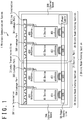
- FIG. 1 is a partial cross-sectional view that shows a configuration example of a wireless communication system 1 according to an embodiment.
- the wireless communication system 1 is provided with a shield room forming section 2, a leaky transmission line 3, a plurality of devices 4, a power supply 5 and a power supply line 50.
- the shield room forming section 2 is provided with a first shield room forming section 2A, a second shield room forming section 2B and a barrier wall 21.
- the first shield room forming section 2A has a first internal space 20A inside.
- the second shield room forming section 2B has a second internal space 20B inside. It should be noted that although a number of shield room forming sections 2A and 2B included in the shield room forming section 2 is two in the configuration example shown in Fig. 1 , it may be three or more. It is needless to say that those numbers are merely examples and do not limit the present embodiment.
- the leaky transmission line 3 is provided with a plurality of leakage parts 30, two ends and two line terminations 391 and 392. In other words, two ends of the leaky transmission line 3 are terminated by two line terminations 391 and 392, respectively.
- the plurality of leakage parts 30 include a first leakage part 30A, a second leakage part 30B and a third leakage part 30C. However, when these leakage parts 30A, 30B and 30C are not distinguished, they may be simply referred to as leakage part(s) 30. It should be noted that the leaky transmission line 3 may further have a non-leakage part from where no electromagnetic wave leaks.
- Each of the plurality of devices 4 is provided with an antenna 400 and a wireless power receiving unit 401.
- the plurality of devices 4 includes a first device 41, a second device 42 and a third device 43.
- the first device 41 is provided with a first antenna 410 and a first wireless power receiving unit 411.
- the second device 42 is provided with a second antenna 420 and a second wireless power receiving unit 421.
- the third device 43 is provided with a third antenna 430 and a third wireless power receiving unit 431.
- these devices 41, 42 and 43 are not distinguished, they may be simply referred to as device(s) 4.
- these antennas 410, 420 and 430 are not distinguished, they may be simply referred to as antenna(s) 400.
- these wireless power receiving units 411, 421 and 431 are note distinguished, they may be simply referred to as wireless power receiving unit(s) 401.
- the power supply line 50 is provided with a plurality of wireless power supply units 51.
- the plurality of wireless power supply units 51 includes a first wireless power supply unit 51A, a second wireless power supply unit 51B and a third wireless power supply unit 51C.
- these wireless power supply units 51A, 51B and 51C may be simply referred to as wireless power supply unit(s) 51.
- the power supply line 50 may be a single path or may be branched into a plurality of branch portions.
- the first shield room forming section 2A and the second shield room forming section 2B are connected by sharing a part of their respective outer walls. These shared outer walls are the barrier wall 21.
- the barrier wall 21 is provided inside the shield room forming section 2 to divide the internal space in the shield room forming section 2 into two spaces; a part of the shield room forming section 2 and the barrier wall 21 that covers the first internal space 20A as a first shield room that is one of the divided internal space is referred to as the first shield room forming section 2A; and a remaining part thereof that covers the second internal space 20B as a second shield room is referred to as the second shield room forming section 2B.
- each of the first internal space 20A covered by the first shield room forming section 2A and the second internal space 20B covered by the second shield room forming section 2B is a shield room blocked from electromagnetic waves and no wireless communication can be performed from one internal space to another internal space.
- the shield room forming section 2, the first shield room forming section 2A, the second shield room forming section 2B and the barrier wall 21 may be constituted of electromagnetic wave reflector that reflects electromagnetic waves.
- the first internal space 20A and the second internal space 20B that are covered by the first shield room forming section 2A and the second shield room forming section 2B, respectively, are preferably covered by electromagnetic wave reflector.
- the first shield room forming section 2A and the second shield room forming section 2B are not necessarily integrated and may exist separately and independently from each other. Furthermore, a combination of a plurality of shield room forming sections that are integrated and a combination of a plurality of shield room forming sections that are separated and independent from each other may simultaneously exist.
- the leaky transmission line 3 may have leakage parts 30 of a same number as the shield room forming sections 2A and 2B or more leakage parts 30 and may have branches. It is needless to say that all ends are preferably terminated by line terminations, respectively, even if the leaky transmission line 3 includes branches.
- the leaky transmission line 3 may be constituted as a leaky waveguide or may be constituted as a leaky coaxial cable.
- a part of the leaky transmission line 3 is arranged inside the first shield room forming section 2A, that is, in a range of the first internal space 20A
- another part of the leaky transmission line 3 is arranged inside the second shield room forming section 2B, that is, in a range of the second internal space 20B.
- the leaky transmission line 3 may be arranged so as to penetrate through the barrier wall 21 as shown in Fig. 1 .
- the leaky transmission line 3 may be arranged so as to detour the barrier wall 21.
- the section of non-leakage part may be constituted as a waveguide or may be constituted as a coaxial cable.
- a general waveguide is a tubular metallic pipe able to propagate electromagnetic waves in longitudinal direction thereof and frequencies of electromagnetic waves with low propagation loss differ in accordance with cross-sectional shape, sizes or the like of the waveguide.
- a leaky waveguide is a waveguide provided with leakage parts on sides thereof and can radiate a part of electromagnetic waves propagating inside to outside through the leakage parts.
- a leaky waveguide can propagate electromagnetic waves, that penetrates through a leakage part from outside to inside, along a longitudinal direction.
- a leakage part of a leaky waveguide is a long and narrow hole opened to penetrate through a side of a metallic pipe and is also referred to as a slot.
- Frequencies, radiation directions and the like of electromagnetic waves that easily comes inside or goes outside a leaky waveguide through a leakage part differ in accordance with shape, sizes and the like of the leakage part.
- a plurality of slots is provided to a leaky waveguide.
- leakage parts of a leaky waveguide function as a plurality of antennas provided along the leaky waveguide.
- a general coaxial cable is a cable able to propagate electromagnetic waves in a longitudinal direction thereof, in which a circumference of a linear center conductor is covered by a cylindrical dielectric and a circumference of this dielectric is covered by a cylindrical external conductor.
- the external conductor is preferably further covered by a cylindrical jacket constituted of insulator.
- a leaky coaxial cable is a coaxial cable provided with leakage parts on external conductor thereof and can radiate a part of electromagnetic waves propagating inside to outside through leakage parts.
- a leaky coaxial cable can propagate electromagnetic waves, that penetrates through leakage parts from outside to inside, along the longitudinal direction.
- a leakage part of a leaky coaxial cable is a long and narrow hole opened to penetrate through the external conductor and is also referred to as a slot. It should be noted that in many cases a plurality of slots is provided to a leaky coaxial cable.
- a leaky coaxial cable with an external conductor wound in spiral with gap around the dielectric also exists. In this case, the gap opened between the spiral external conductor functions as a leakage part.
- the gap is actually constituted in a shape of one spiral, it looks like a plurality of external conductors and a plurality leakage parts arranged alternatively from any point of view and the leaky coaxial cable functions such that a plurality of leakage parts actually exists.
- leakage parts of a leaky coaxial cable function as a plurality of antennas provided along the leaky coaxial cable.
- the leaky transmission line 3 penetrates through the barrier wall 21 and partially penetrates inside the first shield room forming section 2A and inside the second shield room forming section 2B, respectively.
- the first device 41 including the first antenna 410 is further arranged inside the first shield room forming section 2A.
- the second device 42 including the second antenna 420 is further arranged inside the second shield room forming section 2B, as well.
- a device 4 is provided with an antenna 400 and a wireless power receiving unit 401. It should be noted that this means that, as described above, the devices 41, 42 and 43 are provided with the antennas 410, 420 and 430 and the wireless power receiving units 411, 421 and 431, respectively.
- the antenna 400 is connected to a communication circuit that is not illustrated.
- the antenna 400 is coupled with any one(s) of the plurality of leakage parts 30 that the leaky transmission line 3 has, by electromagnetic waves.
- a coupling by electromagnetic waves means that the antenna 400 and the leakage section 30 are configured and arranged so as to be wirelessly communicable with each other.
- a leakage part 30 in electromagnetic wave coupling with the antenna 410 of the first device 41 will be referred to as a first leakage part 30A.
- a second leakage part 30B and a third leakage part 30C are in electromagnetic wave coupling with the antenna 420 of the second device 42 and the antenna 430 of the third device 43, respectively.
- the first leakage part 30A and the third leakage part 30C of the leaky transmission line 3 are arranged inside the first shield room forming section 2A and at least the second leakage part 30B is arranged inside the second shield room forming section 2B.
- the power supply line 50 is connected to the power supply 5 on one hand and is connected to the wireless power supply unit 51 on the other hand.
- the power supply 5 is arranged inside the second shield room forming section 2B, that is, in the second internal space 20B, this is merely a configuration example and does not limit the present embodiment.
- the power supply 5 may be arranged inside the first shield room forming section 2A, that is, in the first internal space 20A, or may be arranged outside the shield room forming section 2.
- a part of the power supply line 50 is arranged inside the first shield room forming section 2A, that is, in the first internal space 20A.
- Another part of the power supply line 50 is arranged inside the second shield room forming section 2B, that is, in the second internal space 20B.
- the power supply line 50 may be arranged so as to penetrate through the barrier wall 21, as shown in Fig. 1 .
- the power supply line 50 may be arranged so as to detour the barrier wall 21.
- the plurality of wireless power supply units 51 and the plurality of wireless power receiving units 401 are arranged so that the latter ones can receive wireless power supply from the first ones, respectively.
- a positional relationship between the first wireless power supply unit 51A and the first wireless power receiving unit 411 is preferably determined so as to enable wireless power supply between them.
- a positional relationship between the second wireless power supply unit 51B and the second wireless power receiving unit 421 is preferably determined so as to enable wireless power supply between them.
- a positional relationship between the third wireless power supply unit 51C and the third wireless power receiving unit 431 is preferably determined so as to enable wireless power supply between them.
- the wireless power supply unit 51 is preferably arranged inside the electromagnetic wave reflector, that is, inside the shield room forming section 2.
- the power supply 5 generates a power to transmit to the wireless power supply unit 51 through the power supply line 50.
- Each wireless power supply unit 51 performs wireless power supply to the wireless power receiving units 401 arranged in a position enabling the wireless power supply.
- the wireless power receiving units 401 supply the power wirelessly supplied from the wireless power supply units 51 to internal circuits of the devices 4 that are not illustrated. These internal circuits include communication circuits.
- the internal circuits of the devices 4 that are not illustrated start to operate by the power supplied from the wireless power receiving units 401.
- the devices 4 are further provided with rechargeable batteries, that are to be charged with the power supplied by the wireless power receiving units 401 and supply the charged power to the communication circuits, and charge-discharge circuits.
- the devices 4 in operation perform, as necessary, transmission and reception of signal via the antennas 400.
- the antennas 400 enable two-way communication with other devices 4 via the leakage parts 30 in electromagnetic wave coupling with themselves and the leaky transmission line 3.
- the leaky transmission line 3 functions as a mere two-way propagation path. That is, in a conventional method of using a leaky transmission line 3, when performing wireless communication between a plurality of devices 4 in electromagnetic wave coupling with leakage parts 30 of a leaky transmission line 3, it was common that an access point connected to the leaky transmission line 3 by wire mediates this wireless communication. In other words, at first, one device 4 performs communication with the access point and then the access point performs communication with another device 4, and thus both devices 4 could perform communication with each other.
- a wireless communication can be performed directly between both devices 4.
- a wireless communication can be performed directly even between a first device 41 arranged in the first internal space 20A and the second device 42 arranged in the second internal space 20B.
- a wireless communication can be directly performed between the first device 41 and the third device 43 that are arranged in the same first internal space 20A, as well.
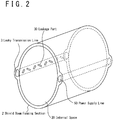
- FIG. 2 is a partial cross-sectional view that shows another configuration example of a wireless communication system 1 according to an embodiment.
- the leaky transmission line 3 and the power supply line 50 are integrated to the shield room forming section 2.
- illustrations of devices 4 is omitted for a better visual recognition.
- the leaky transmission line 3 in Fig. 2 is integrated to the shield room forming section 2, as described above. More specifically, the leaky transmission line 3 in Fig. 2 is a leaky waveguide and its metallic pipe is integrated to the shield room forming section 2. Therefore, it is preferable that the entire shield room forming section 2 is made of metal. It should be noted that if the whole is non-metallic, a metal film may be formed on a surface inside or outside the leaky waveguide.
- the leakage parts 30 are constituted as slots that penetrate through the shield room forming section 2 so that a hollow part of the leaky waveguide is connected to the internal space 20. Such a structure can be relatively easily manufactured by using techniques of so-called three-dimensional printers, for example.
- the leaky transmission line 3 in the present variation example with a leaky coaxial cable
- the external conductor of the leaky coaxial cable is considered to be integrated to the shield room forming section 2 and the center conductor is arranged in a hollow part of the leaky waveguide in Fig. 2 so as not to be conductive with the shield room forming section 2. Furthermore, a remaining space of the hollow part between the center conductor and the shield room forming section 2 is filled with dielectric.
- power supply line 50 is a well-known technique. It should be noted that in the configuration example in Fig. 2 , since the shield room forming section 2 is made of metal, it can be used as a ground.
- the leaky transmission line 3 and the power supply line 50 are arranged so as to protrude outside the shield room forming section 2 in order to make a shape of the internal space 20 cylindrical.
- this is a mere example and is not to limit a shape of the wireless communication system 1 according to the present embodiment.
- Fig. 3 is a partial cross-sectional view that shows a configuration example of a flying object 11 according to a related art.
- the flying object 11 in Fig. 3 is provided with a body 12, a fuel tank 122, a first device 14A, a second device 14B, a wire harness 123 and a protective cover 124.
- the fuel tank 122 is arranged inside the body 12.
- the existence of the fuel tank 122 is very important and in many cases a central part of the body 12 is occupied by the fuel tank 122.
- a high symmetry is required for the shape of the fuel tank 122.
- the shape of the fuel tank 122 is almost cylindrical.
- the internal space of the body 12 is physically divided by the fuel tank 122 into a first internal space 120A of the front and a second internal space 120B of the rear.
- a part of the body 12 and the fuel tank 122 that covers the first internal space 120A can be considered as a pseudo first shield room forming section 12A.
- a part of the body 12 and the fuel tank 122 that covers the second internal space 120B can be considered as a pseudo second shield room forming section 12B.
- the first device 14A is arranged in the first internal space 120A and the second device 14B is arranged in the second internal space 120B.
- the first device 14A and the second device 14B are electrically connected via the wire harness 123.
- the wire harness 123 that connects the first device 14A and the second device 14B is arranged outside the body 12 in order to detour the fuel tank 122.
- the protective cover 124 to protect the wire harness 123 is provided on the outer surface of the flying object 11. This is because when the flying object 11 flies at high speed high heat is generated on the outer surface of the body 12 due to aerodynamic heating and the wire harness 123 needs to be protected from this high heat. In addition, a performance of protecting the wire harness 123 from outside electromagnetic wave noises is also required to the protective cover 124.
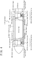
- Fig. 4 is a partial cross-sectional view that shows a configuration example of a flying object 11 according to an embodiment.
- the flying object 11 in Fig. 4 is provided with a body 12, a fuel tank 122, a leaky transmission line 13, a first device 141, a second device 142, a power supply 15, a power supply line 150, a first wireless power supply unit 151A and a second wireless power supply unit 151B.
- the leaky transmission line 13 is provided with leakage parts 130A and 130B and line terminations 1391 and 1392.
- the first device 141 is provided with a first antenna 1410 and a first wireless power receiving unit 1411.
- the second device 142 is provided with a second antenna 1420 and a second wireless power receiving unit 1421.
- the fuel tank 122 is arranged inside the body 12 and the internal space of the body 12 is physically divided by the fuel tank 122 into the first internal space 120A of the front and the second internal space 120B of the rear.
- a part of the body 12 and the fuel tank 122 that covers first internal space 120A can be considered as a pseudo first shield room forming section 12A.
- a part of the body 12 and the fuel tank 122 that covers the second internal space 120B can be considered as a pseudo second shield room forming section 12B.
- the first device 141 is arranged in the first internal space 120A and the second device 142 is arranged in the second internal space 120B.
- the leaky transmission line 13 and the power supply line 150 are integrated to the body 12. As the positional relationship of the body 12, the leaky transmission line 13 and the power supply line 150 in Fig. 4 is similar to the positional relationship of the shield room forming section 2, the leaky transmission line 3 and the power supply line 50 shown in Fig. 2 , further detailed description thereof will be omitted.
- the first leakage part 130A is provided so as to penetrate through a part of the body 12 that is sandwiched between the leaky transmission line 13 and the first internal space 120A.
- the first antenna 1410 is arranged near the first leakage part 130A so as to be able to be in electromagnetic wave coupling with the first leakage part 130A, so as to enable a wireless communication between the first antenna 1410 and the first leakage part 130A in other words.
- the second leakage part 130B is provided so as to penetrate through a part of the body 12 that is sandwiched between leaky transmission line 13 and the second internal space 120B.
- the second antenna 1420 is arranged near the second leakage part 130B so as to be able to be in electromagnetic wave coupling with the second leakage part 130B, so as to enable a wireless communication between the second antenna 1420 and the second leakage part 130B, in other words.
- the power supply 15 is connected to the first wireless power supply unit 151A and the second wireless power supply unit 151B via the power supply line 150.
- the first wireless power supply unit 151A and the second wireless power supply unit 151B are integrated to the body 12 in the configuration example in Fig. 4 , this is merely one configuration example and does not limit configurations of the present embodiment. That is, the power supply 15 may be arranged in any of the first internal space 120A and the second internal space 120B.
- the first wireless power supply unit 151A and the second wireless power supply unit 151B may be arranged in the first internal space 120A and the second internal space 120B, respectively.
- the first wireless power supply unit 151A is arranged near the first wireless power receiving unit 1411 so as to be able to wirelessly supply power to the first wireless power receiving unit 1411 of the first device 141.
- the second wireless power supply unit 151B is arranged near the second wireless power receiving unit 1421 so as to be able to wirelessly supply power to the second wireless power receiving unit 1421 of the second device 142.
- the power supply 15 generates power to transmit to the wireless power supply units 151A and 151B via the power supply line 150.
- Wireless power supply units 151A and 151B perform wireless power supply to the wireless power receiving units 1411 and 1412 that are arranged at positions where wireless power supply is possible.
- the wireless power receiving units 1411 and 1421 supply the power that is wirelessly supplied from the wireless power supply units 151A and 151B to internal circuits of the devices 141 and 142 that are not illustrated. Those internal circuits include communication circuits.
- the internal circuits of the devices 141 and 142 that are not illustrated start and operate with the power supplied by the wireless power receiving units 1411 and 1421. It should be noted that it is preferable that the devices 141 and 142 are further provided with rechargeable batteries, that are to be charged with the power supplied by the wireless power receiving units 1411 and 1421 and supply the charged power to the internal circuits, and charge-discharge circuits.
- the devices 141 and 142 in operation perform, as necessary, transmission and reception of signals via antennas 1410 and 1420.
- the antennas 1410 and 1420 enable two-way communication between other devices 142 and 141 via the leakage parts 130A and 130B, that are in electromagnetic wave coupling, and the leaky transmission line 13.
- leaky transmission line 13 functions as two-way propagation path, that an access point to mediate is not necessary when a wireless communication is performed between the first device 141 and the second device 142, that power supply to the first device 141 and the second device 142 may be performed by wire, and the like, because it is similar to the case of the first embodiment.
- an access point to mediate is not necessary when a wireless communication is performed between a plurality of devices 4, 141 and 142.
- an access point may be added and that functions can be added by adding an access point.
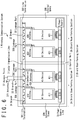
- FIG. 5 is a partial cross-sectional view that shows a configuration example of a wireless communication system 1 according to an embodiment.
- Fig. 6 is a partial cross-sectional view that shows another configuration example of a wireless communication system 1 according to an embodiment.
- the wireless communication system 1 according to the configuration example in Fig. 5 is equivalent to the wireless communication system 1 in Fig. 1 added with a connection 38, a branch 33 and a line termination 393. That is, in Fig. 5 , the connection 38 is added between the first line termination 391 and the second line termination 392 of the leaky transmission line 3.
- This connection 38 is a branch point of the leaky transmission line 3.
- a part of the leaky transmission line 3 from the connection 38 to the first line termination 391 will be referred to as a first branch 31
- a part from the connection 38 to the second line termination 392 will be referred to as a second branch 32
- a part from the connection 38 to the third line termination 393 will be referred to as a third branch 33.
- the third branch 33 downstream of the third branch 33, there is a third end terminated by the third line termination 393.
- a part of the third branch 33 that includes an end connected to the connection 38 is arranged inside the shield room forming section 2, while a remaining part including the third line termination 393 penetrates through the shield room forming section 2 and is arranged outside the shield room forming section 2.
- the end of the third branch 33 that is arranged outside the shield room forming section 2 may be referred to as an external end.
- the third line termination 393 may be referred to as an external line termination.
- the wireless communication system 1 according to the configuration example in Fig. 6 is equivalent to the wireless communication system 1 in Fig. 5 without the third line termination 393 removed from the third branch 33 and added with an access point 37 connected to an end of the third branch 33 instead.
- the third line termination 393 is detachably attached to the end of the third branch 33 and can be replaced to the access point 37.
- the access point 37 is provided with an antenna 371.
- the access point 37 and its antenna 371 are arranged outside the shield room forming section 2.
- the access point 37 can perform a wireless communication with an arbitrary communication device existing outside the wireless communication system 1 via the antenna 371 thereof.
- the access point 37 can perform a wireless communication with the device 4 arranged in the shield room forming section 2 via the leaky transmission line 3.
- a contactless wireless communication can be performed between a device 4 existing in an internal space 20A or 20B shielded by an electromagnetic wave reflector and an arbitrary communication device existing outside the shield room forming section 2.
- the wireless communication system 1 according to the present embodiment will be described as a specific example when applied to the flying object 11 in Fig. 4 in this regard.
- a flying object 11 may be subjected to a test before being used.
- a test by connecting a relay device corresponding to the access point 37 to the leaky transmission line 13, a wireless communication can be performed between an arbitrary checking device, that is prepared outside the flying object 11 and connected to the relay device, and the devices 141 and 142 via the relay device.
- function check, program update and the like can be performed to the devices 141 and 142 without physically manipulating the devices 141 and 142 inside the body 12.
- the relay device corresponding to the access point 37 can be removed from the leaky transmission line 13 and an arbitrary terminating device corresponding to the line termination 393 can be connected instead.
Landscapes
- Engineering & Computer Science (AREA)
- Computer Networks & Wireless Communication (AREA)
- Signal Processing (AREA)
- Physics & Mathematics (AREA)
- Electromagnetism (AREA)
- Astronomy & Astrophysics (AREA)
- Aviation & Aerospace Engineering (AREA)
- General Physics & Mathematics (AREA)
- Remote Sensing (AREA)
- Near-Field Transmission Systems (AREA)
- Mobile Radio Communication Systems (AREA)
Abstract
Description
- The present invention relates to a wireless communication system and a flying object equipped with the wireless communication system.
- A technique of performing a wireless communication in a shield room by use of a leaky transmission line such as a leaky coaxial cable and a leaky waveguide is known. Herein, a shield room refers to a space where a wireless communication by use of an electromagnetic wave is difficult or impossible between inside and outside, such as a narrow space and a closed space. In addition, a wireless communication by an electromagnetic wave may be difficult or impossible in an internal space of a shield room as well. According to this techniques, a distribution of an electromagnetic wave in a narrow space can be made uniform by use of a leaky transmission line as an antenna connected to an access point, in a room, in a space inside a tunnel or the like.
- On the other hand, there is a need for a wireless communication performed between a plurality of devices arranged inside one or more shield rooms. In particular, there is a need for a wireless communication performed directly and mutually between a plurality of devices without using any access point that may be a base unit.
- For example, to perform a wired communication between two devices arranged at a front and a rear of a flying object, it is necessary to provide a communication line between them. At that time, the communication line may need to detour components arranged between them, such as a fuel tank or an engine, and the communication line may need to pass outside the flying object in this purpose. However, a surface of a flying object is exposed to high temperatures when the flying object is flying at high speed. In addition, the flying object is exposed outside itself to external electromagnetics noises as well. In addition, there is a case where, even though two devices try a wireless communication with each other, as a space where each device is arranged is covered with an electromagnetic wave reflector, the wireless communication cannot be performed.
- In relation to the above, a description related to a wireless communication is disclosed in Patent Literature 1 (
WO 2008/004577 A1 ). This wireless communication system is provided with a plurality of wireless stations provided in a structure with a radio wave shield arranged at a fixed position. This wireless communication system is characterized in that at least one of a pair of wireless stations having a radio channel same to each other and a pair of wireless stations having another radio channel adjacent to each other is arranged on both sides of the radio wave shield. - The wireless communication system in Patent Literature 1 (
WO 2008/004577 A1 ) is a technology of optimizing arrangement of wireless stations considering electromagnetic wave reflectors and absorbers, in wireless communication inside an aircraft. In other words, in thePatent Literature 1, a target thereof is limited to a wireless communication inside a single narrow space and no wireless communication across a plurality of closed spaces can be realized. - In addition, an invention related to a closed space transmitting apparatus is disclosed in Patent Literature 2 (Japanese Patent No.
4657332 B2 - The closed space transmitting apparatus of the Patent Literature 2 (Japanese Patent No.
4657332 B2 - In addition, an invention related to an electromagnetic wave propagation apparatus is disclosed in Patent Literature 3 (Japanese Patent No.
5695744 B2 - The electromagnetic wave propagation apparatus in the Patent Literature 3 (Japanese Patent No.
5695744 B2 5695744 B2 - In addition, a description related to a communication system between a mobile station and a fixed station is disclosed in Patent Literature 4 (Japanese Patent Publication No.
2016-217711 A - The communication system in the Patent Literature 4 (Japanese Patent Publication No.
2016-217711 A -
- [Patent Literature 1]
WO 2008/004577 A1 - [Patent Literature 2] Japanese Patent No.
4657332 B2 - [Patent Literature 3] Japanese Patent No.
5695744 B2 - [Patent Literature 4] Japanese Patent Publication No.
2016-217711 A - A wireless communication system, in that a wireless communication can be performed directly and mutually between a plurality of communication devices arranged inside one or more shield room forming sections, and a flying object using this wireless communication system will be provided. Other problems and new features will be clarified by descriptions of the present Specification and attached drawings.
- According to an embodiment, a wireless communication system is provided with a shield room forming section, a leaky transmission line, a first antenna, a first device, a second antenna and a second device. Herein, the shield room forming section covers an internal space as a shield room with an electromagnetic wave reflector that blocks wireless communication. The leaky transmission line is provided with a first leakage part and a second leakage part arranged inside the shield room forming section. It should be noted that the leaky transmission line may further have a non-leakage part from where no electromagnetic wave leaks. The first antenna is arranged inside the shield room forming section and is configured to be wirelessly communicable with the first leakage part. The first device is arranged inside the shield room forming section and has the first antenna. The second antenna is arranged inside the shield room forming section and is configured to be wirelessly communicable with the second leakage part. The second device is arranged inside the shield room forming section and has the second antenna. The first device and the second device perform a direct two-way wireless communication mutually and through the leaky transmission line. It should be noted that the first device and the second device may perform two-way wireless communication without using the leaky transmission line. The leaky transmission line may be a single path or may be branched into a plurality of paths.
- According to an embodiment, a flying body is provided with a body, a leaky transmission line, a first antenna, a first device, a second antenna and a second device. Herein, the body covers an internal space with an electromagnetic wave reflector that blocks wireless communication. The leaky transmission line is provided with a first leakage part and a second leakage part arranged inside the body. The first antenna is arranged inside the body and is configured to be wirelessly communicable with the first leakage part. The first device is arranged inside the body and has the first antenna. The second antenna is arranged inside the body and is configured to be wirelessly communicable with the second leakage part. The second device is arranged inside the body and has the second antenna. The first device and the second device perform a direct two-way wireless communication through the leaky transmission line.
- According the above-mentioned embodiment, a wireless communication system, in that a direct two-way wireless communication can be performed between a plurality of communication devices respectively arranged inside one or more shield room forming sections by providing a leaky transmission line passing through one or more shield rooms, and a flying body using this wireless communication system can be realized.
-
- [
Fig. 1] Fig. 1 is a partial cross-sectional view that shows a configuration example of a wireless communication system according to an embodiment. - [
Fig. 2] Fig. 2 is a partial cross-sectional view that shows another configuration example of a wireless communication system according to an embodiment. - [
Fig. 3] Fig. 3 is a partial cross-sectional view that shows a configuration example of a flying object according to a related art. - [
Fig. 4] Fig. 4 is a partial cross-sectional view that shows a configuration example of a flying object according to an embodiment. - [
Fig. 5] Fig. 5 is a partial cross-sectional view that shows a configuration example of a wireless communication system according to an embodiment. - [
Fig. 6] Fig. 6 is a partial cross-sectional view that shows another configuration example of a wireless communication system according to an embodiment. - Embodiments to carry out a wireless communication system and a flying object according to the present invention will be described below with reference to attached drawings. Herein, a flying object includes a manned or unmanned rocket, a missile, a manned or unmanned aircraft, an artificial satellite, and the like.
- A device that performs wireless communication may be arranged in a shield room covered with an electromagnetic wave reflector that blocks wireless communication using electromagnetic wave. A container that covers an internal space as a shield room will be referred to as "shield room forming section" for convenience. It should be noted that a shape of the shield room forming section is arbitrary. In addition, the internal space as the shield room of the shield room forming section may be completely closed, may have some gaps, and furthermore may include a mesh structure sized to block specific communication frequencies. In the present embodiment of wireless communication system, a leaky transmission line is used as a two-way transmission line of electromagnetic waves. That is, for example, a leaky transmission line is provided so as to pass through two shield rooms and a direct two-way wireless communication is performed through the leaky transmission line between two devices arranged inside respective shield rooms. Herein, it is to be noted that performing a two-way wireless communication without using any access point that mediates two devices is expressed as "direct".
- A configuration example of a
wireless communication system 1 according to an embodiment will be described with reference toFig. 1. Fig. 1 is a partial cross-sectional view that shows a configuration example of awireless communication system 1 according to an embodiment. - Components of the
wireless communication system 1 inFig. 1 will be described. Thewireless communication system 1 is provided with a shieldroom forming section 2, aleaky transmission line 3, a plurality ofdevices 4, apower supply 5 and apower supply line 50. Herein, the shieldroom forming section 2 is provided with a first shieldroom forming section 2A, a second shieldroom forming section 2B and abarrier wall 21. The first shieldroom forming section 2A has a firstinternal space 20A inside. Similarly, the second shieldroom forming section 2B has a secondinternal space 20B inside. It should be noted that although a number of shieldroom forming sections room forming section 2 is two in the configuration example shown inFig. 1 , it may be three or more. It is needless to say that those numbers are merely examples and do not limit the present embodiment. - The
leaky transmission line 3 is provided with a plurality ofleakage parts 30, two ends and twoline terminations leaky transmission line 3 are terminated by twoline terminations leakage parts 30 include afirst leakage part 30A, asecond leakage part 30B and athird leakage part 30C. However, when theseleakage parts leaky transmission line 3 may further have a non-leakage part from where no electromagnetic wave leaks. - Each of the plurality of
devices 4 is provided with anantenna 400 and a wirelesspower receiving unit 401. The plurality ofdevices 4 includes afirst device 41, asecond device 42 and athird device 43. Thefirst device 41 is provided with afirst antenna 410 and a first wirelesspower receiving unit 411. Similarly, thesecond device 42 is provided with asecond antenna 420 and a second wirelesspower receiving unit 421. In addition, thethird device 43 is provided with athird antenna 430 and a third wirelesspower receiving unit 431. However, when thesedevices antennas power receiving units - The
power supply line 50 is provided with a plurality of wirelesspower supply units 51. The plurality of wirelesspower supply units 51 includes a first wirelesspower supply unit 51A, a second wirelesspower supply unit 51B and a third wirelesspower supply unit 51C. However, when these wirelesspower supply units power supply line 50 may be a single path or may be branched into a plurality of branch portions. - Connections and arrangement of components of the
wireless communication system 1 inFig. 1 will be described. In the configuration example inFig. 1 , the first shieldroom forming section 2A and the second shieldroom forming section 2B are connected by sharing a part of their respective outer walls. These shared outer walls are thebarrier wall 21. In other words: thebarrier wall 21 is provided inside the shieldroom forming section 2 to divide the internal space in the shieldroom forming section 2 into two spaces; a part of the shieldroom forming section 2 and thebarrier wall 21 that covers the firstinternal space 20A as a first shield room that is one of the divided internal space is referred to as the first shieldroom forming section 2A; and a remaining part thereof that covers the secondinternal space 20B as a second shield room is referred to as the second shieldroom forming section 2B. - It should be noted that in the present embodiment, as a premise, each of the first
internal space 20A covered by the first shieldroom forming section 2A and the secondinternal space 20B covered by the second shieldroom forming section 2B is a shield room blocked from electromagnetic waves and no wireless communication can be performed from one internal space to another internal space. Thus, the shieldroom forming section 2, the first shieldroom forming section 2A, the second shieldroom forming section 2B and thebarrier wall 21 may be constituted of electromagnetic wave reflector that reflects electromagnetic waves. At least, the firstinternal space 20A and the secondinternal space 20B that are covered by the first shieldroom forming section 2A and the second shieldroom forming section 2B, respectively, are preferably covered by electromagnetic wave reflector. In addition, in this sense, the first shieldroom forming section 2A and the second shieldroom forming section 2B are not necessarily integrated and may exist separately and independently from each other. Furthermore, a combination of a plurality of shield room forming sections that are integrated and a combination of a plurality of shield room forming sections that are separated and independent from each other may simultaneously exist. At that time, theleaky transmission line 3 may haveleakage parts 30 of a same number as the shieldroom forming sections more leakage parts 30 and may have branches. It is needless to say that all ends are preferably terminated by line terminations, respectively, even if theleaky transmission line 3 includes branches. - The
leaky transmission line 3 may be constituted as a leaky waveguide or may be constituted as a leaky coaxial cable. In any case, a part of theleaky transmission line 3 is arranged inside the first shieldroom forming section 2A, that is, in a range of the firstinternal space 20A, and another part of theleaky transmission line 3 is arranged inside the second shieldroom forming section 2B, that is, in a range of the secondinternal space 20B. At that time, theleaky transmission line 3 may be arranged so as to penetrate through thebarrier wall 21 as shown inFig. 1 . Alternatively, theleaky transmission line 3 may be arranged so as to detour thebarrier wall 21. In addition, there may be a section of non-leakage part that does not radiate electromagnetic waves between eachleakage part 30. The section of non-leakage part may be constituted as a waveguide or may be constituted as a coaxial cable. - A more specific configuration example of a case in which the
leaky transmission line 3 is a leaky waveguide will be described. A general waveguide is a tubular metallic pipe able to propagate electromagnetic waves in longitudinal direction thereof and frequencies of electromagnetic waves with low propagation loss differ in accordance with cross-sectional shape, sizes or the like of the waveguide. A leaky waveguide is a waveguide provided with leakage parts on sides thereof and can radiate a part of electromagnetic waves propagating inside to outside through the leakage parts. Conversely, a leaky waveguide can propagate electromagnetic waves, that penetrates through a leakage part from outside to inside, along a longitudinal direction. In general, a leakage part of a leaky waveguide is a long and narrow hole opened to penetrate through a side of a metallic pipe and is also referred to as a slot. Frequencies, radiation directions and the like of electromagnetic waves that easily comes inside or goes outside a leaky waveguide through a leakage part differ in accordance with shape, sizes and the like of the leakage part. It should be noted that in many cases a plurality of slots is provided to a leaky waveguide. In addition, in this sense, it may be considered that leakage parts of a leaky waveguide function as a plurality of antennas provided along the leaky waveguide. - A more specific configuration example of a case in which a
leaky transmission line 3 is a leaky coaxial cable will be described. A general coaxial cable is a cable able to propagate electromagnetic waves in a longitudinal direction thereof, in which a circumference of a linear center conductor is covered by a cylindrical dielectric and a circumference of this dielectric is covered by a cylindrical external conductor. The external conductor is preferably further covered by a cylindrical jacket constituted of insulator. A leaky coaxial cable is a coaxial cable provided with leakage parts on external conductor thereof and can radiate a part of electromagnetic waves propagating inside to outside through leakage parts. Conversely, a leaky coaxial cable can propagate electromagnetic waves, that penetrates through leakage parts from outside to inside, along the longitudinal direction. In general, a leakage part of a leaky coaxial cable is a long and narrow hole opened to penetrate through the external conductor and is also referred to as a slot. It should be noted that in many cases a plurality of slots is provided to a leaky coaxial cable. In addition, as another configuration example, a leaky coaxial cable with an external conductor wound in spiral with gap around the dielectric also exists. In this case, the gap opened between the spiral external conductor functions as a leakage part. At that time, although the gap is actually constituted in a shape of one spiral, it looks like a plurality of external conductors and a plurality leakage parts arranged alternatively from any point of view and the leaky coaxial cable functions such that a plurality of leakage parts actually exists. In addition, in this sense, it can be also considered that leakage parts of a leaky coaxial cable function as a plurality of antennas provided along the leaky coaxial cable. - In the configuration example in
Fig. 1 , theleaky transmission line 3 penetrates through thebarrier wall 21 and partially penetrates inside the first shieldroom forming section 2A and inside the second shieldroom forming section 2B, respectively. Thefirst device 41 including thefirst antenna 410 is further arranged inside the first shieldroom forming section 2A. Similarly, thesecond device 42 including thesecond antenna 420 is further arranged inside the second shieldroom forming section 2B, as well. - A
device 4 is provided with anantenna 400 and a wirelesspower receiving unit 401. It should be noted that this means that, as described above, thedevices antennas power receiving units device 4, theantenna 400 is connected to a communication circuit that is not illustrated. On the other hand, in eachdevice 4, theantenna 400 is coupled with any one(s) of the plurality ofleakage parts 30 that theleaky transmission line 3 has, by electromagnetic waves. Herein, a coupling by electromagnetic waves means that theantenna 400 and theleakage section 30 are configured and arranged so as to be wirelessly communicable with each other. Herein, aleakage part 30 in electromagnetic wave coupling with theantenna 410 of thefirst device 41 will be referred to as afirst leakage part 30A. Similarly, asecond leakage part 30B and athird leakage part 30C are in electromagnetic wave coupling with theantenna 420 of thesecond device 42 and theantenna 430 of thethird device 43, respectively. In the configuration example inFig. 1 , thefirst leakage part 30A and thethird leakage part 30C of theleaky transmission line 3 are arranged inside the first shieldroom forming section 2A and at least thesecond leakage part 30B is arranged inside the second shieldroom forming section 2B. - The
power supply line 50 is connected to thepower supply 5 on one hand and is connected to the wirelesspower supply unit 51 on the other hand. Although in the configuration example inFig. 1 thepower supply 5 is arranged inside the second shieldroom forming section 2B, that is, in the secondinternal space 20B, this is merely a configuration example and does not limit the present embodiment. Thepower supply 5 may be arranged inside the first shieldroom forming section 2A, that is, in the firstinternal space 20A, or may be arranged outside the shieldroom forming section 2. - A part of the
power supply line 50 is arranged inside the first shieldroom forming section 2A, that is, in the firstinternal space 20A. Another part of thepower supply line 50 is arranged inside the second shieldroom forming section 2B, that is, in the secondinternal space 20B. At that time, thepower supply line 50 may be arranged so as to penetrate through thebarrier wall 21, as shown inFig. 1 . Alternatively, thepower supply line 50 may be arranged so as to detour thebarrier wall 21. - The plurality of wireless
power supply units 51 and the plurality of wirelesspower receiving units 401 are arranged so that the latter ones can receive wireless power supply from the first ones, respectively. In other words, a positional relationship between the first wirelesspower supply unit 51A and the first wirelesspower receiving unit 411 is preferably determined so as to enable wireless power supply between them. Similarly, a positional relationship between the second wirelesspower supply unit 51B and the second wirelesspower receiving unit 421 is preferably determined so as to enable wireless power supply between them. In addition, a positional relationship between the third wirelesspower supply unit 51C and the third wirelesspower receiving unit 431 is preferably determined so as to enable wireless power supply between them. It should be noted that it is needless to say that the wirelesspower supply unit 51 is preferably arranged inside the electromagnetic wave reflector, that is, inside the shieldroom forming section 2. - Operations of components of the
wireless communication system 1 inFig. 1 will be described. At first, thepower supply 5 generates a power to transmit to the wirelesspower supply unit 51 through thepower supply line 50. Each wirelesspower supply unit 51 performs wireless power supply to the wirelesspower receiving units 401 arranged in a position enabling the wireless power supply. The wirelesspower receiving units 401 supply the power wirelessly supplied from the wirelesspower supply units 51 to internal circuits of thedevices 4 that are not illustrated. These internal circuits include communication circuits. The internal circuits of thedevices 4 that are not illustrated start to operate by the power supplied from the wirelesspower receiving units 401. It should be noted that it is preferable that thedevices 4 are further provided with rechargeable batteries, that are to be charged with the power supplied by the wirelesspower receiving units 401 and supply the charged power to the communication circuits, and charge-discharge circuits. Thedevices 4 in operation perform, as necessary, transmission and reception of signal via theantennas 400. Theantennas 400 enable two-way communication withother devices 4 via theleakage parts 30 in electromagnetic wave coupling with themselves and theleaky transmission line 3. - Herein, it is to be noted that when performing wireless communications between a plurality of
devices 4, theleaky transmission line 3 functions as a mere two-way propagation path. That is, in a conventional method of using aleaky transmission line 3, when performing wireless communication between a plurality ofdevices 4 in electromagnetic wave coupling withleakage parts 30 of aleaky transmission line 3, it was common that an access point connected to theleaky transmission line 3 by wire mediates this wireless communication. In other words, at first, onedevice 4 performs communication with the access point and then the access point performs communication with anotherdevice 4, and thus bothdevices 4 could perform communication with each other. However, in the present embodiment, even if two ormore devices 4 are arranged in a sameinternal space 20 or even if two ormore devices 4 are arranged in a plurality of differentinternal spaces 20, respectively, a wireless communication can be performed directly between bothdevices 4. Specifically, in the configuration example inFig. 1 , a wireless communication can be performed directly even between afirst device 41 arranged in the firstinternal space 20A and thesecond device 42 arranged in the secondinternal space 20B. In addition, a wireless communication can be directly performed between thefirst device 41 and thethird device 43 that are arranged in the same firstinternal space 20A, as well. - It should be noted that it is needless to say that although a wireless power supply is used in the above description, a similar wireless communication can be performed by supplying the
devices 4 with power by wire, as well. However, by realizing both wireless communication and wireless power supply, installation of thedevices 4 in the shieldroom forming sections 2, assembly of thewireless communication system 1, and the like can be greatly simplified. This leads to improvement of productivity. In addition, by commonizing interfaces of wireless communication and wireless power supply between the plurality ofdevices 4, improvement in degree of freedom in combination ofdevices 4, expandability and the like can be expected as well. - A variation example of the present embodiment will be described with reference to
Fig. 2. Fig. 2 is a partial cross-sectional view that shows another configuration example of awireless communication system 1 according to an embodiment. In the variation example shown inFig. 2 , theleaky transmission line 3 and thepower supply line 50 are integrated to the shieldroom forming section 2. In addition, inFig. 2 , illustrations ofdevices 4 is omitted for a better visual recognition. - The
leaky transmission line 3 inFig. 2 is integrated to the shieldroom forming section 2, as described above. More specifically, theleaky transmission line 3 inFig. 2 is a leaky waveguide and its metallic pipe is integrated to the shieldroom forming section 2. Therefore, it is preferable that the entire shieldroom forming section 2 is made of metal. It should be noted that if the whole is non-metallic, a metal film may be formed on a surface inside or outside the leaky waveguide. Herein, theleakage parts 30 are constituted as slots that penetrate through the shieldroom forming section 2 so that a hollow part of the leaky waveguide is connected to theinternal space 20. Such a structure can be relatively easily manufactured by using techniques of so-called three-dimensional printers, for example. - It should be noted that in case of constituting the
leaky transmission line 3 in the present variation example with a leaky coaxial cable, following modification may be made, for example. The external conductor of the leaky coaxial cable is considered to be integrated to the shieldroom forming section 2 and the center conductor is arranged in a hollow part of the leaky waveguide inFig. 2 so as not to be conductive with the shieldroom forming section 2. Furthermore, a remaining space of the hollow part between the center conductor and the shieldroom forming section 2 is filled with dielectric. - Detailed description about
power supply line 50 is omitted because it is a well-known technique. It should be noted that in the configuration example inFig. 2 , since the shieldroom forming section 2 is made of metal, it can be used as a ground. - In the configuration example in
Fig. 2 , theleaky transmission line 3 and thepower supply line 50 are arranged so as to protrude outside the shieldroom forming section 2 in order to make a shape of theinternal space 20 cylindrical. However, this is a mere example and is not to limit a shape of thewireless communication system 1 according to the present embodiment. - In the present embodiment, the configuration of the
wireless communication system 1 according to the first embodiment will be applied to a configuration of a flying object. Although it is a repetition of the above described "Background Art", a configuration example of a flying object according to a related art will be described with reference toFig. 3 at first for a better understanding of the present embodiment.Fig. 3 is a partial cross-sectional view that shows a configuration example of a flyingobject 11 according to a related art. - Components of the flying
object 11 inFig. 3 will be described. The flyingobject 11 inFig. 3 is provided with abody 12, afuel tank 122, afirst device 14A, asecond device 14B, awire harness 123 and aprotective cover 124. - Connection relationships and positional relationships of the components of the flying
object 11 inFig. 3 will be described. Thefuel tank 122 is arranged inside thebody 12. In the flyingobject 11, the existence of thefuel tank 122 is very important and in many cases a central part of thebody 12 is occupied by thefuel tank 122. In addition, a high symmetry is required for the shape of thefuel tank 122. Specifically, it is preferable that the shape of thefuel tank 122 is almost cylindrical. As a result, the internal space of thebody 12 is physically divided by thefuel tank 122 into a firstinternal space 120A of the front and a secondinternal space 120B of the rear. Thus, a part of thebody 12 and thefuel tank 122 that covers the firstinternal space 120A can be considered as a pseudo first shieldroom forming section 12A. Similarly, a part of thebody 12 and thefuel tank 122 that covers the secondinternal space 120B can be considered as a pseudo second shieldroom forming section 12B. At that time, thefirst device 14A is arranged in the firstinternal space 120A and thesecond device 14B is arranged in the secondinternal space 120B. - The
first device 14A and thesecond device 14B are electrically connected via thewire harness 123. Thewire harness 123 that connects thefirst device 14A and thesecond device 14B is arranged outside thebody 12 in order to detour thefuel tank 122. Theprotective cover 124 to protect thewire harness 123 is provided on the outer surface of the flyingobject 11. This is because when the flyingobject 11 flies at high speed high heat is generated on the outer surface of thebody 12 due to aerodynamic heating and thewire harness 123 needs to be protected from this high heat. In addition, a performance of protecting thewire harness 123 from outside electromagnetic wave noises is also required to theprotective cover 124. - Next, a flying
object 11 according to the present embodiment will be described with reference toFig. 4. Fig. 4 is a partial cross-sectional view that shows a configuration example of a flyingobject 11 according to an embodiment. - Components of the flying
object 11 inFig. 4 will be described. The flyingobject 11 inFig. 4 is provided with abody 12, afuel tank 122, aleaky transmission line 13, afirst device 141, asecond device 142, apower supply 15, apower supply line 150, a first wirelesspower supply unit 151A and a second wirelesspower supply unit 151B. Theleaky transmission line 13 is provided withleakage parts line terminations first device 141 is provided with afirst antenna 1410 and a first wirelesspower receiving unit 1411. Similarly, thesecond device 142 is provided with asecond antenna 1420 and a second wirelesspower receiving unit 1421. - Connection relationships and positional relationships of components of the flying
object 11 inFig. 4 will be described. Similar to the case inFig. 3 , thefuel tank 122 is arranged inside thebody 12 and the internal space of thebody 12 is physically divided by thefuel tank 122 into the firstinternal space 120A of the front and the secondinternal space 120B of the rear. In addition, a part of thebody 12 and thefuel tank 122 that covers firstinternal space 120A can be considered as a pseudo first shieldroom forming section 12A. Similarly, a part of thebody 12 and thefuel tank 122 that covers the secondinternal space 120B can be considered as a pseudo second shieldroom forming section 12B. At that time, thefirst device 141 is arranged in the firstinternal space 120A and thesecond device 142 is arranged in the secondinternal space 120B. - The
leaky transmission line 13 and thepower supply line 150 are integrated to thebody 12. As the positional relationship of thebody 12, theleaky transmission line 13 and thepower supply line 150 inFig. 4 is similar to the positional relationship of the shieldroom forming section 2, theleaky transmission line 3 and thepower supply line 50 shown inFig. 2 , further detailed description thereof will be omitted. - The
first leakage part 130A is provided so as to penetrate through a part of thebody 12 that is sandwiched between theleaky transmission line 13 and the firstinternal space 120A. Thefirst antenna 1410 is arranged near thefirst leakage part 130A so as to be able to be in electromagnetic wave coupling with thefirst leakage part 130A, so as to enable a wireless communication between thefirst antenna 1410 and thefirst leakage part 130A in other words. - Similarly, the
second leakage part 130B is provided so as to penetrate through a part of thebody 12 that is sandwiched betweenleaky transmission line 13 and the secondinternal space 120B. Thesecond antenna 1420 is arranged near thesecond leakage part 130B so as to be able to be in electromagnetic wave coupling with thesecond leakage part 130B, so as to enable a wireless communication between thesecond antenna 1420 and thesecond leakage part 130B, in other words. - The
power supply 15 is connected to the first wirelesspower supply unit 151A and the second wirelesspower supply unit 151B via thepower supply line 150. Although the first wirelesspower supply unit 151A and the second wirelesspower supply unit 151B are integrated to thebody 12 in the configuration example inFig. 4 , this is merely one configuration example and does not limit configurations of the present embodiment. That is, thepower supply 15 may be arranged in any of the firstinternal space 120A and the secondinternal space 120B. In addition, the first wirelesspower supply unit 151A and the second wirelesspower supply unit 151B may be arranged in the firstinternal space 120A and the secondinternal space 120B, respectively. In any case, the first wirelesspower supply unit 151A is arranged near the first wirelesspower receiving unit 1411 so as to be able to wirelessly supply power to the first wirelesspower receiving unit 1411 of thefirst device 141. Similarly, the second wirelesspower supply unit 151B is arranged near the second wirelesspower receiving unit 1421 so as to be able to wirelessly supply power to the second wirelesspower receiving unit 1421 of thesecond device 142. - Operations of the components of the flying
object 11 inFig. 4 will be described. Similar to the case of thewireless communication system 1 inFig. 1 , at first, thepower supply 15 generates power to transmit to the wirelesspower supply units power supply line 150. Wirelesspower supply units power receiving units 1411 and 1412 that are arranged at positions where wireless power supply is possible. The wirelesspower receiving units power supply units devices devices power receiving units devices power receiving units devices antennas antennas other devices leakage parts leaky transmission line 13. - Moreover, further detailed descriptions will be omitted in that
leaky transmission line 13 functions as two-way propagation path, that an access point to mediate is not necessary when a wireless communication is performed between thefirst device 141 and thesecond device 142, that power supply to thefirst device 141 and thesecond device 142 may be performed by wire, and the like, because it is similar to the case of the first embodiment. - As effects obtained in the present embodiment, it can be mentioned that, in addition to effects obtained in the first embodiment, the problem in that outer part of the flying
object 11 is exposed to high heat, electromagnetic noises and the like is resolved because thewire harness 123 of the related art shown inFig. 3 is no longer necessary. As a result, the design of the flyingobject 11 as a whole becomes easier. In addition, a reliability of the flyingobject 11 as a whole is improved because external factors can be reduced. - In the first and second embodiments, it was described that an access point to mediate is not necessary when a wireless communication is performed between a plurality of
devices - A
wireless communication system 1 according to the present embodiment will be described with reference toFig. 5 andFig. 6 .Fig. 5 is a partial cross-sectional view that shows a configuration example of awireless communication system 1 according to an embodiment.Fig. 6 is a partial cross-sectional view that shows another configuration example of awireless communication system 1 according to an embodiment. - The
wireless communication system 1 according to the configuration example inFig. 5 is equivalent to thewireless communication system 1 inFig. 1 added with aconnection 38, abranch 33 and aline termination 393. That is, inFig. 5 , theconnection 38 is added between thefirst line termination 391 and thesecond line termination 392 of theleaky transmission line 3. Thisconnection 38 is a branch point of theleaky transmission line 3. Herein, for convenience, a part of theleaky transmission line 3 from theconnection 38 to thefirst line termination 391 will be referred to as afirst branch 31, a part from theconnection 38 to thesecond line termination 392 will be referred to as asecond branch 32 and a part from theconnection 38 to thethird line termination 393 will be referred to as athird branch 33. In other words, downstream of thethird branch 33, there is a third end terminated by thethird line termination 393. A part of thethird branch 33 that includes an end connected to theconnection 38 is arranged inside the shieldroom forming section 2, while a remaining part including thethird line termination 393 penetrates through the shieldroom forming section 2 and is arranged outside the shieldroom forming section 2. The end of thethird branch 33 that is arranged outside the shieldroom forming section 2 may be referred to as an external end. Similarly, thethird line termination 393 may be referred to as an external line termination. - The
wireless communication system 1 according to the configuration example inFig. 6 is equivalent to thewireless communication system 1 inFig. 5 without thethird line termination 393 removed from thethird branch 33 and added with anaccess point 37 connected to an end of thethird branch 33 instead. In other words, thethird line termination 393 is detachably attached to the end of thethird branch 33 and can be replaced to theaccess point 37. Theaccess point 37 is provided with anantenna 371. Theaccess point 37 and itsantenna 371 are arranged outside the shieldroom forming section 2. In other words, theaccess point 37 can perform a wireless communication with an arbitrary communication device existing outside thewireless communication system 1 via theantenna 371 thereof. On the other hand, theaccess point 37 can perform a wireless communication with thedevice 4 arranged in the shieldroom forming section 2 via theleaky transmission line 3. - In other words, in the
wireless communication system 1 according to the present embodiment, a contactless wireless communication can be performed between adevice 4 existing in aninternal space room forming section 2. Thewireless communication system 1 according to the present embodiment will be described as a specific example when applied to the flyingobject 11 inFig. 4 in this regard. - In general, a flying
object 11 may be subjected to a test before being used. When performing a test, by connecting a relay device corresponding to theaccess point 37 to theleaky transmission line 13, a wireless communication can be performed between an arbitrary checking device, that is prepared outside the flyingobject 11 and connected to the relay device, and thedevices devices devices body 12. - It should be noted that after the test is completed the relay device corresponding to the
access point 37 can be removed from theleaky transmission line 13 and an arbitrary terminating device corresponding to theline termination 393 can be connected instead. - Although the invention made by the inventor(s) has been specifically described above based on embodiments, it is needless to say that the present invention is not limited by the above described embodiments and various modifications can be made thereto without departing from the scope thereof. In addition, each feature described in the above described embodiments can be freely combined as long as there is no technical contradiction.
- It should be noted that the present application claims priority based on Japanese Patent Application No.
2018-033872 filed on February 27, 2018
Claims (17)
- A wireless communication system comprising:a shield room forming section configured to cover an internal space as a shield room with an electromagnetic wave reflector that blocks wireless communication;a leaky transmission line comprising a first leakage part and a second leakage part arranged inside the shield room forming section;a first antenna arranged inside the shield room forming section and configured to be wirelessly communicable with the first leakage part;a first device arranged inside the shield room forming section and having the first antenna;a second antenna arranged inside the shield room forming section and configured to be wirelessly communicable with the second leakage part; anda second device arranged inside the shield room forming section and having the second antenna,wherein the first device and the second device perform a direct two-way communication through the leaky transmission line.
- The wireless communication system according to claim 1,
wherein the shield room forming section comprises:a barrier wall configured to divide the internal space into a first internal space, as a first shield room that includes the first device, the first antenna and the first leakage part, and a second internal space, as a second shield room that includes the second device, the first antenna and the second leakage part;a first shield room forming section configured to cover the first internal space with the electromagnetic wave reflector; anda second shield room forming section configured to cover the second internal space with the electromagnetic wave reflector, andwherein the leaky transmission line penetrates through the barrier wall. - The wireless communication system according to claim 1,
wherein the shield room forming section comprises:a barrier wall configured to divide the internal space into a first internal space, as a first shield room that includes the first device, the first antenna and the first leakage part, and a second internal space, as a second shield room that includes the second device, the first antenna and the second leakage part;a first shield room forming section configured to cover the first internal space with the electromagnetic wave reflector; anda second shield room forming section configured to cover the second internal space with the electromagnetic wave reflector,wherein the leaky transmission line detours the barrier wall. - A wireless communication system comprising:a first shield room forming section configured to cover a first internal space, as a first shield room, with an electromagnetic wave reflector that blocks wireless communication;a second shield room forming section that exists separately and independently from the first shield room forming section and is configured to cover a second internal space, as a second shield room that is different from the first shield room, with the electromagnetic wave reflector;a leaky transmission line comprising a first leakage part arranged inside the first internal space and a second leakage part arranged inside the second internal space;a first antenna arranged inside the first shield room forming section and configured to be wirelessly communicable with the first leakage part;a first device arranged inside the first shield room forming section and having the first antenna;a second antenna arranged inside the second shield room forming section and configured to be wirelessly communicable with the second leakage part; anda second device arranged inside the second shield room forming section and having the second antenna,wherein the first device and the second device perform a direct two-way communication through the leaky transmission line.
- The wireless communication system according to any one of claims 2 to 4, further comprising a third shield room forming section configured to cover a third internal space, as a third shield room different from the first shield room and the second shield room, with the electromagnetic wave reflector,
wherein the leaky transmission line further comprises a third leakage part arranged inside the third shield room forming section,
the wireless communication system further comprising:a third antenna arranged inside the third shield room forming section and configured to be wirelessly communicable with the third leakage part; anda third device arranged inside the third shield room forming section and connected to the third antenna. - The wireless communication system according to any one of claims 1 to 5, wherein all ends of the leaky transmission line are terminated.
- The wireless communication system according to any one of claims 1 to 6,
wherein the leaky transmission line comprises a leaky waveguide, and
wherein the leaky waveguide is integrated with the electromagnetic wave reflector. - The wireless communication system according to any one of claims 1 to 6,
wherein the leaky transmission line further comprises a leaky coaxial cable,
wherein the leaky coaxial cable comprises:a center conductor;a dielectric arranged around the center conductor; andan external conductor arranged around the dielectric and integrated with the electromagnetic wave reflector. - The wireless communication system according to any one of claims 6 to 8,
wherein the leaky transmission line further comprises:an external end among the all ends, the external end being arranged outside the electromagnetic wave reflector; andan external line termination removably mounted to the external end to terminate the external end. - The wireless communication system according to any one of claims 1 to 7, further comprising:a power supply; anda wireless power supply unit connected by wire to the power supply to wirelessly supply power to the first device and arranged inside the electromagnetic wave reflector,wherein the first device further comprises a wireless power receiving unit arranged so as to be wirelessly powered by the wireless power supply unit.
- A flying object comprising:a body configured to cover an internal space with an electromagnetic wave reflector that blocks wireless communication;a leaky transmission line comprising a first leakage part and a second leakage part arranged inside the body;a first antenna arranged inside the body and configured to be wirelessly communicable with the first leakage part;a first device arranged inside the body and having the first antenna;a second antenna arranged inside the body and configured to be wirelessly communicable with the second leakage part; anda second device arranged inside the body and having the second antenna,wherein the first device and the second device perform a direct two-way communication through the leaky transmission line.
- The flying object according to claim 11, wherein all ends of the leaky transmission line are terminated.
- The flying object according to claim 11 or 12,
wherein the leaky transmission line comprises a leaky waveguide, and
wherein the leaky waveguide is integrated with the body. - The flying object according to claim 11 or 12,
wherein the leaky transmission line comprises a leaky coaxial cable, and
wherein the leaky coaxial cable comprises:a center conductor;a dielectric arranged around the center conductor; andan external conductor arranged around the dielectric and integrated with the body. - The flying object according to any one of claims 11 to 14,
wherein the body comprises:a fuel tank configured to divide the internal space into a first internal space, as a first shield room including the first device, the first antenna and the first leakage part, and a second internal space, as a second shield room including the second device, the second antenna and the second leakage part;a first shield room forming section configured to cover the first internal space with the electromagnetic wave reflector; anda second shield room forming section configured to cover the second internal space with the electromagnetic wave reflector, andwherein the leaky transmission line detours the fuel tank. - The flying object according to any one of claims 11 to 15, wherein the leaky transmission line further comprises:an external end among the all ends, the external end being arranged outside the body; andan external line termination removably mounted to the external end to terminate the external end.
- The flying object according to any one of claims 11 to 16, further comprising:a power supply;a power supply line connected to the power supply; anda wireless power supply unit arranged inside the body and connected to the power supply line to wirelessly supply power to the first device,wherein the first device comprises a wireless power receiving unit configured to receive a wireless power supply from the wireless power supply unit.
Applications Claiming Priority (2)
| Application Number | Priority Date | Filing Date | Title |
|---|---|---|---|
| JP2018033872A JP7224762B2 (en) | 2018-02-27 | 2018-02-27 | Wireless communication systems and projectiles |
| PCT/JP2018/038480 WO2019167333A1 (en) | 2018-02-27 | 2018-10-16 | Wireless communication system and flying object |
Publications (3)
| Publication Number | Publication Date |
|---|---|
| EP3758243A1 true EP3758243A1 (en) | 2020-12-30 |
| EP3758243A4 EP3758243A4 (en) | 2021-04-07 |
| EP3758243B1 EP3758243B1 (en) | 2025-08-20 |
Family
ID=67804910
Family Applications (1)
| Application Number | Title | Priority Date | Filing Date |
|---|---|---|---|
| EP18908109.4A Active EP3758243B1 (en) | 2018-02-27 | 2018-10-16 | Wireless communication system and flying object |
Country Status (4)
| Country | Link |
|---|---|
| US (1) | US11943006B2 (en) |
| EP (1) | EP3758243B1 (en) |
| JP (1) | JP7224762B2 (en) |
| WO (1) | WO2019167333A1 (en) |
Families Citing this family (1)
| Publication number | Priority date | Publication date | Assignee | Title |
|---|---|---|---|---|
| EP4120477B1 (en) * | 2021-07-16 | 2026-03-04 | Schneider Electric Industries SAS | Antenna module for wireless electromagnetic wave communication inside an electrical cabinet, leaky wave antenna comprising a plurality of antenna modules, and switchgear installation comprising such leaky wave antenna |
Family Cites Families (20)
| Publication number | Priority date | Publication date | Assignee | Title |
|---|---|---|---|---|
| BE834291A (en) * | 1975-10-07 | 1976-02-02 | RADIOCOMMUNICATIONS SYSTEM FOR CONFINED AREAS | |
| JPS5627540U (en) | 1979-08-09 | 1981-03-14 | ||
| JPS5627540A (en) * | 1979-08-14 | 1981-03-17 | Toyo Commun Equip Co Ltd | Single-frequency special radio communication system |
| JPS594353Y2 (en) | 1979-12-21 | 1984-02-08 | 富士通株式会社 | Portable voting information display |
| US6219553B1 (en) * | 1997-03-31 | 2001-04-17 | Texas Instruments Incorporated | Low power wireless network using desktop antenna |
| JP3749513B2 (en) * | 2002-06-25 | 2006-03-01 | 東芝テック株式会社 | Wireless communication system |
| US20070176840A1 (en) * | 2003-02-06 | 2007-08-02 | James Pristas | Multi-receiver communication system with distributed aperture antenna |
| JP2007134642A (en) | 2005-11-14 | 2007-05-31 | Toshiba Tec Corp | Wireless security room and wireless security system |
| US20090052386A1 (en) | 2006-07-04 | 2009-02-26 | Masaaki Higashida | Radio communication system |
| JP2008283508A (en) | 2007-05-11 | 2008-11-20 | Matsushita Electric Ind Co Ltd | Wireless communication system |
| JP4657332B2 (en) | 2008-08-29 | 2011-03-23 | 日本放送協会 | Closed space transmitter |
| JP4913186B2 (en) * | 2009-08-13 | 2012-04-11 | 東芝テック株式会社 | Wireless communication system and installation method thereof |
| JP2011199760A (en) * | 2010-03-23 | 2011-10-06 | Sony Corp | Bundled leaky transmission line, communication apparatus, and communication system |
| JP5627540B2 (en) | 2011-06-17 | 2014-11-19 | 三菱電機株式会社 | Injection locking oscillator |
| US9362605B2 (en) | 2011-07-11 | 2016-06-07 | Hitachi, Ltd. | Electromagnetic wave propagation path and electromagnetic wave propagation device |
| JP5443447B2 (en) * | 2011-07-21 | 2014-03-19 | 株式会社日本自動車部品総合研究所 | Vehicle power line communication system and transmitter |
| JP2015080310A (en) | 2013-10-16 | 2015-04-23 | 日立金属株式会社 | Device, system and method for non-contact power supply |
| JP6636268B2 (en) | 2015-05-14 | 2020-01-29 | 株式会社日立製作所 | Communication system and communication method between mobile station and fixed station |
| JP5948688B2 (en) | 2015-11-09 | 2016-07-06 | 株式会社国際電気通信基礎技術研究所 | Wireless communication apparatus and wireless communication method |
| JP2018033872A (en) | 2016-09-02 | 2018-03-08 | テルモ株式会社 | Medical tube |
-
2018
- 2018-02-27 JP JP2018033872A patent/JP7224762B2/en active Active
- 2018-10-16 WO PCT/JP2018/038480 patent/WO2019167333A1/en not_active Ceased
- 2018-10-16 US US16/975,516 patent/US11943006B2/en active Active
- 2018-10-16 EP EP18908109.4A patent/EP3758243B1/en active Active
Also Published As
| Publication number | Publication date |
|---|---|
| JP2019149737A (en) | 2019-09-05 |
| US11943006B2 (en) | 2024-03-26 |
| EP3758243A4 (en) | 2021-04-07 |
| US20210036430A1 (en) | 2021-02-04 |
| WO2019167333A1 (en) | 2019-09-06 |
| EP3758243B1 (en) | 2025-08-20 |
| JP7224762B2 (en) | 2023-02-20 |
Similar Documents
| Publication | Publication Date | Title |
|---|---|---|
| KR102589691B1 (en) | Antenna units and terminal equipment | |
| US11043741B2 (en) | Antenna array system for producing dual polarization signals | |
| US11069981B2 (en) | Radiating cable and method of manufacturing a radiating cable with an inner and outer conductor, each having openings | |
| EP3497743B1 (en) | Dielectric groove waveguide | |
| US4152648A (en) | Radiocommunication system for confined spaces | |
| US10938119B2 (en) | Wireless communication device and antenna device | |
| ES2350831T3 (en) | COMMUNICATION SYSTEM OF MULTIPLE RECEIVERS WITH ANTENNA OF DISTRIBUTED OPENINGS. | |
| US11309623B2 (en) | Antenna device | |
| KR102479577B1 (en) | Dual band multi-beam antenna apparauts with frequency divider/combiner and multi-beam antenna for 5g mobile communication | |
| CN116073112A (en) | Antenna and base station equipment | |
| JP2013141251A (en) | Low noise index aperture antenna | |
| US11943006B2 (en) | Wireless communication system using a leaky transmission line for direct two-way communication and usable in a flying object | |
| JP6386403B2 (en) | Antenna device | |
| JP2014531173A (en) | Distributed antenna system and method for manufacturing distributed antenna system | |
| KR102465551B1 (en) | Multi-band transmit antenna device | |
| CN112993591B (en) | Antenna array and vehicle including the same | |
| US10186757B2 (en) | Antenna and wireless device | |
| WO2021215161A1 (en) | Multimode waveguide antenna | |
| KR100761597B1 (en) | Broadband leakage coaxial cable | |
| Bhattacharyya et al. | Multiband feed using coaxial configuration | |
| JP2021536189A (en) | Coupling device, surface wave coupling method and bare wire surface wave wireless coverage system | |
| US3177488A (en) | Broad band microwave radio link | |
| KR100780147B1 (en) | Broadband leakage coaxial cable | |
| EP3032638B1 (en) | Radiating cable and method of manufacturing a radiating cable | |
| EP3032637B1 (en) | Radiating cable and method of manufacturing a radiating cable |
Legal Events
| Date | Code | Title | Description |
|---|---|---|---|
| STAA | Information on the status of an ep patent application or granted ep patent |
Free format text: STATUS: THE INTERNATIONAL PUBLICATION HAS BEEN MADE |
|
| PUAI | Public reference made under article 153(3) epc to a published international application that has entered the european phase |
Free format text: ORIGINAL CODE: 0009012 |
|
| STAA | Information on the status of an ep patent application or granted ep patent |
Free format text: STATUS: REQUEST FOR EXAMINATION WAS MADE |
|
| 17P | Request for examination filed |
Effective date: 20200924 |
|
| AK | Designated contracting states |
Kind code of ref document: A1 Designated state(s): AL AT BE BG CH CY CZ DE DK EE ES FI FR GB GR HR HU IE IS IT LI LT LU LV MC MK MT NL NO PL PT RO RS SE SI SK SM TR |
|
| AX | Request for extension of the european patent |
Extension state: BA ME |
|
| A4 | Supplementary search report drawn up and despatched |
Effective date: 20210309 |
|
| RIC1 | Information provided on ipc code assigned before grant |
Ipc: H01Q 13/00 20060101ALI20210302BHEP Ipc: H04B 5/00 20060101AFI20210302BHEP Ipc: B64D 47/00 20060101ALI20210302BHEP |
|
| DAV | Request for validation of the european patent (deleted) | ||
| DAX | Request for extension of the european patent (deleted) | ||
| STAA | Information on the status of an ep patent application or granted ep patent |
Free format text: STATUS: EXAMINATION IS IN PROGRESS |
|
| 17Q | First examination report despatched |
Effective date: 20221212 |
|
| REG | Reference to a national code |
Ref country code: DE Ref legal event code: R079 Free format text: PREVIOUS MAIN CLASS: H04B0005000000 Ipc: H01Q0013200000 Ref country code: DE Ref legal event code: R079 Ref document number: 602018084856 Country of ref document: DE Free format text: PREVIOUS MAIN CLASS: H04B0005000000 Ipc: H01Q0013200000 |
|
| GRAP | Despatch of communication of intention to grant a patent |
Free format text: ORIGINAL CODE: EPIDOSNIGR1 |
|
| STAA | Information on the status of an ep patent application or granted ep patent |
Free format text: STATUS: GRANT OF PATENT IS INTENDED |
|
| RIC1 | Information provided on ipc code assigned before grant |
Ipc: B64D 47/00 20060101ALN20250227BHEP Ipc: H04B 5/28 20240101ALI20250227BHEP Ipc: H01Q 1/28 20060101ALI20250227BHEP Ipc: H01Q 13/20 20060101AFI20250227BHEP |
|
| INTG | Intention to grant announced |
Effective date: 20250324 |
|
| GRAS | Grant fee paid |
Free format text: ORIGINAL CODE: EPIDOSNIGR3 |
|
| GRAA | (expected) grant |
Free format text: ORIGINAL CODE: 0009210 |
|
| STAA | Information on the status of an ep patent application or granted ep patent |
Free format text: STATUS: THE PATENT HAS BEEN GRANTED |
|
| AK | Designated contracting states |
Kind code of ref document: B1 Designated state(s): AL AT BE BG CH CY CZ DE DK EE ES FI FR GB GR HR HU IE IS IT LI LT LU LV MC MK MT NL NO PL PT RO RS SE SI SK SM TR |
|
| REG | Reference to a national code |
Ref country code: GB Ref legal event code: FG4D |
|
| REG | Reference to a national code |
Ref country code: CH Ref legal event code: EP |
|
| REG | Reference to a national code |
Ref country code: IE Ref legal event code: FG4D |
|
| REG | Reference to a national code |
Ref country code: DE Ref legal event code: R096 Ref document number: 602018084856 Country of ref document: DE |
|
| REG | Reference to a national code |
Ref country code: NL Ref legal event code: MP Effective date: 20250820 |
|
| PG25 | Lapsed in a contracting state [announced via postgrant information from national office to epo] |
Ref country code: IS Free format text: LAPSE BECAUSE OF FAILURE TO SUBMIT A TRANSLATION OF THE DESCRIPTION OR TO PAY THE FEE WITHIN THE PRESCRIBED TIME-LIMIT Effective date: 20251220 |
|
| PGFP | Annual fee paid to national office [announced via postgrant information from national office to epo] |
Ref country code: DE Payment date: 20251028 Year of fee payment: 8 |
|
| PGFP | Annual fee paid to national office [announced via postgrant information from national office to epo] |
Ref country code: GB Payment date: 20251029 Year of fee payment: 8 |
|
| PG25 | Lapsed in a contracting state [announced via postgrant information from national office to epo] |
Ref country code: NO Free format text: LAPSE BECAUSE OF FAILURE TO SUBMIT A TRANSLATION OF THE DESCRIPTION OR TO PAY THE FEE WITHIN THE PRESCRIBED TIME-LIMIT Effective date: 20251120 |
|
| REG | Reference to a national code |
Ref country code: LT Ref legal event code: MG9D |
|
| PG25 | Lapsed in a contracting state [announced via postgrant information from national office to epo] |
Ref country code: PT Free format text: LAPSE BECAUSE OF FAILURE TO SUBMIT A TRANSLATION OF THE DESCRIPTION OR TO PAY THE FEE WITHIN THE PRESCRIBED TIME-LIMIT Effective date: 20251222 |
|
| PG25 | Lapsed in a contracting state [announced via postgrant information from national office to epo] |
Ref country code: FI Free format text: LAPSE BECAUSE OF FAILURE TO SUBMIT A TRANSLATION OF THE DESCRIPTION OR TO PAY THE FEE WITHIN THE PRESCRIBED TIME-LIMIT Effective date: 20250820 |
|
| PGFP | Annual fee paid to national office [announced via postgrant information from national office to epo] |
Ref country code: IT Payment date: 20251212 Year of fee payment: 8 |
|
| PG25 | Lapsed in a contracting state [announced via postgrant information from national office to epo] |
Ref country code: HR Free format text: LAPSE BECAUSE OF FAILURE TO SUBMIT A TRANSLATION OF THE DESCRIPTION OR TO PAY THE FEE WITHIN THE PRESCRIBED TIME-LIMIT Effective date: 20250820 Ref country code: NL Free format text: LAPSE BECAUSE OF FAILURE TO SUBMIT A TRANSLATION OF THE DESCRIPTION OR TO PAY THE FEE WITHIN THE PRESCRIBED TIME-LIMIT Effective date: 20250820 |
|
| PGFP | Annual fee paid to national office [announced via postgrant information from national office to epo] |
Ref country code: FR Payment date: 20251024 Year of fee payment: 8 |
|
| PG25 | Lapsed in a contracting state [announced via postgrant information from national office to epo] |
Ref country code: GR Free format text: LAPSE BECAUSE OF FAILURE TO SUBMIT A TRANSLATION OF THE DESCRIPTION OR TO PAY THE FEE WITHIN THE PRESCRIBED TIME-LIMIT Effective date: 20251121 |
|
| PG25 | Lapsed in a contracting state [announced via postgrant information from national office to epo] |
Ref country code: SE Free format text: LAPSE BECAUSE OF FAILURE TO SUBMIT A TRANSLATION OF THE DESCRIPTION OR TO PAY THE FEE WITHIN THE PRESCRIBED TIME-LIMIT Effective date: 20250820 |
|
| PG25 | Lapsed in a contracting state [announced via postgrant information from national office to epo] |
Ref country code: LV Free format text: LAPSE BECAUSE OF FAILURE TO SUBMIT A TRANSLATION OF THE DESCRIPTION OR TO PAY THE FEE WITHIN THE PRESCRIBED TIME-LIMIT Effective date: 20250820 |
|
| PG25 | Lapsed in a contracting state [announced via postgrant information from national office to epo] |
Ref country code: PL Free format text: LAPSE BECAUSE OF FAILURE TO SUBMIT A TRANSLATION OF THE DESCRIPTION OR TO PAY THE FEE WITHIN THE PRESCRIBED TIME-LIMIT Effective date: 20250820 Ref country code: BG Free format text: LAPSE BECAUSE OF FAILURE TO SUBMIT A TRANSLATION OF THE DESCRIPTION OR TO PAY THE FEE WITHIN THE PRESCRIBED TIME-LIMIT Effective date: 20250820 |
|
| PG25 | Lapsed in a contracting state [announced via postgrant information from national office to epo] |
Ref country code: RS Free format text: LAPSE BECAUSE OF FAILURE TO SUBMIT A TRANSLATION OF THE DESCRIPTION OR TO PAY THE FEE WITHIN THE PRESCRIBED TIME-LIMIT Effective date: 20251120 |
|
| PG25 | Lapsed in a contracting state [announced via postgrant information from national office to epo] |
Ref country code: ES Free format text: LAPSE BECAUSE OF FAILURE TO SUBMIT A TRANSLATION OF THE DESCRIPTION OR TO PAY THE FEE WITHIN THE PRESCRIBED TIME-LIMIT Effective date: 20250820 |
|
| REG | Reference to a national code |
Ref country code: AT Ref legal event code: MK05 Ref document number: 1828382 Country of ref document: AT Kind code of ref document: T Effective date: 20250820 |
|
| PG25 | Lapsed in a contracting state [announced via postgrant information from national office to epo] |
Ref country code: RO Free format text: LAPSE BECAUSE OF FAILURE TO SUBMIT A TRANSLATION OF THE DESCRIPTION OR TO PAY THE FEE WITHIN THE PRESCRIBED TIME-LIMIT Effective date: 20250820 |
|
| PG25 | Lapsed in a contracting state [announced via postgrant information from national office to epo] |
Ref country code: SM Free format text: LAPSE BECAUSE OF FAILURE TO SUBMIT A TRANSLATION OF THE DESCRIPTION OR TO PAY THE FEE WITHIN THE PRESCRIBED TIME-LIMIT Effective date: 20250820 |
|
| PG25 | Lapsed in a contracting state [announced via postgrant information from national office to epo] |
Ref country code: DK Free format text: LAPSE BECAUSE OF FAILURE TO SUBMIT A TRANSLATION OF THE DESCRIPTION OR TO PAY THE FEE WITHIN THE PRESCRIBED TIME-LIMIT Effective date: 20250820 |
|
| PG25 | Lapsed in a contracting state [announced via postgrant information from national office to epo] |
Ref country code: AT Free format text: LAPSE BECAUSE OF FAILURE TO SUBMIT A TRANSLATION OF THE DESCRIPTION OR TO PAY THE FEE WITHIN THE PRESCRIBED TIME-LIMIT Effective date: 20250820 |
|
| PG25 | Lapsed in a contracting state [announced via postgrant information from national office to epo] |
Ref country code: CZ Free format text: LAPSE BECAUSE OF FAILURE TO SUBMIT A TRANSLATION OF THE DESCRIPTION OR TO PAY THE FEE WITHIN THE PRESCRIBED TIME-LIMIT Effective date: 20250820 |
|
| PG25 | Lapsed in a contracting state [announced via postgrant information from national office to epo] |
Ref country code: SK Free format text: LAPSE BECAUSE OF FAILURE TO SUBMIT A TRANSLATION OF THE DESCRIPTION OR TO PAY THE FEE WITHIN THE PRESCRIBED TIME-LIMIT Effective date: 20250820 Ref country code: EE Free format text: LAPSE BECAUSE OF FAILURE TO SUBMIT A TRANSLATION OF THE DESCRIPTION OR TO PAY THE FEE WITHIN THE PRESCRIBED TIME-LIMIT Effective date: 20250820 |