EP3758219A1 - Motor control system, motor control device, and bearing life diagnosis method - Google Patents
Motor control system, motor control device, and bearing life diagnosis method Download PDFInfo
- Publication number
- EP3758219A1 EP3758219A1 EP18906840.6A EP18906840A EP3758219A1 EP 3758219 A1 EP3758219 A1 EP 3758219A1 EP 18906840 A EP18906840 A EP 18906840A EP 3758219 A1 EP3758219 A1 EP 3758219A1
- Authority
- EP
- European Patent Office
- Prior art keywords
- lifetime
- motor
- motor control
- bearing
- control apparatus
- Prior art date
- Legal status (The legal status is an assumption and is not a legal conclusion. Google has not performed a legal analysis and makes no representation as to the accuracy of the status listed.)
- Withdrawn
Links
Images



Classifications
-
- G—PHYSICS
- G05—CONTROLLING; REGULATING
- G05B—CONTROL OR REGULATING SYSTEMS IN GENERAL; FUNCTIONAL ELEMENTS OF SUCH SYSTEMS; MONITORING OR TESTING ARRANGEMENTS FOR SUCH SYSTEMS OR ELEMENTS
- G05B23/00—Testing or monitoring of control systems or parts thereof
- G05B23/02—Electric testing or monitoring
- G05B23/0205—Electric testing or monitoring by means of a monitoring system capable of detecting and responding to faults
- G05B23/0259—Electric testing or monitoring by means of a monitoring system capable of detecting and responding to faults characterized by the response to fault detection
- G05B23/0283—Predictive maintenance, e.g. involving the monitoring of a system and, based on the monitoring results, taking decisions on the maintenance schedule of the monitored system; Estimating remaining useful life [RUL]
-
- F—MECHANICAL ENGINEERING; LIGHTING; HEATING; WEAPONS; BLASTING
- F16—ENGINEERING ELEMENTS AND UNITS; GENERAL MEASURES FOR PRODUCING AND MAINTAINING EFFECTIVE FUNCTIONING OF MACHINES OR INSTALLATIONS; THERMAL INSULATION IN GENERAL
- F16C—SHAFTS; FLEXIBLE SHAFTS; ELEMENTS OR CRANKSHAFT MECHANISMS; ROTARY BODIES OTHER THAN GEARING ELEMENTS; BEARINGS
- F16C19/00—Bearings with rolling contact, for exclusively rotary movement
- F16C19/02—Bearings with rolling contact, for exclusively rotary movement with bearing balls essentially of the same size in one or more circular rows
- F16C19/04—Bearings with rolling contact, for exclusively rotary movement with bearing balls essentially of the same size in one or more circular rows for radial load mainly
- F16C19/06—Bearings with rolling contact, for exclusively rotary movement with bearing balls essentially of the same size in one or more circular rows for radial load mainly with a single row or balls
-
- F—MECHANICAL ENGINEERING; LIGHTING; HEATING; WEAPONS; BLASTING
- F16—ENGINEERING ELEMENTS AND UNITS; GENERAL MEASURES FOR PRODUCING AND MAINTAINING EFFECTIVE FUNCTIONING OF MACHINES OR INSTALLATIONS; THERMAL INSULATION IN GENERAL
- F16C—SHAFTS; FLEXIBLE SHAFTS; ELEMENTS OR CRANKSHAFT MECHANISMS; ROTARY BODIES OTHER THAN GEARING ELEMENTS; BEARINGS
- F16C19/00—Bearings with rolling contact, for exclusively rotary movement
- F16C19/52—Bearings with rolling contact, for exclusively rotary movement with devices affected by abnormal or undesired conditions
-
- F—MECHANICAL ENGINEERING; LIGHTING; HEATING; WEAPONS; BLASTING
- F16—ENGINEERING ELEMENTS AND UNITS; GENERAL MEASURES FOR PRODUCING AND MAINTAINING EFFECTIVE FUNCTIONING OF MACHINES OR INSTALLATIONS; THERMAL INSULATION IN GENERAL
- F16C—SHAFTS; FLEXIBLE SHAFTS; ELEMENTS OR CRANKSHAFT MECHANISMS; ROTARY BODIES OTHER THAN GEARING ELEMENTS; BEARINGS
- F16C41/00—Other accessories, e.g. devices integrated in the bearing not relating to the bearing function as such
-
- G—PHYSICS
- G01—MEASURING; TESTING
- G01M—TESTING STATIC OR DYNAMIC BALANCE OF MACHINES OR STRUCTURES; TESTING OF STRUCTURES OR APPARATUS, NOT OTHERWISE PROVIDED FOR
- G01M13/00—Testing of machine parts
- G01M13/04—Bearings
-
- G—PHYSICS
- G01—MEASURING; TESTING
- G01R—MEASURING ELECTRIC VARIABLES; MEASURING MAGNETIC VARIABLES
- G01R31/00—Arrangements for testing electric properties; Arrangements for locating electric faults; Arrangements for electrical testing characterised by what is being tested not provided for elsewhere
- G01R31/34—Testing dynamo-electric machines
- G01R31/343—Testing dynamo-electric machines in operation
-
- H—ELECTRICITY
- H02—GENERATION; CONVERSION OR DISTRIBUTION OF ELECTRIC POWER
- H02P—CONTROL OR REGULATION OF ELECTRIC MOTORS, ELECTRIC GENERATORS OR DYNAMO-ELECTRIC CONVERTERS; CONTROLLING TRANSFORMERS, REACTORS OR CHOKE COILS
- H02P23/00—Arrangements or methods for the control of AC motors characterised by a control method other than vector control
- H02P23/0077—Characterised by the use of a particular software algorithm
-
- H—ELECTRICITY
- H02—GENERATION; CONVERSION OR DISTRIBUTION OF ELECTRIC POWER
- H02P—CONTROL OR REGULATION OF ELECTRIC MOTORS, ELECTRIC GENERATORS OR DYNAMO-ELECTRIC CONVERTERS; CONTROLLING TRANSFORMERS, REACTORS OR CHOKE COILS
- H02P31/00—Arrangements for regulating or controlling electric motors not provided for in groups H02P1/00 - H02P5/00, H02P7/00 or H02P21/00 - H02P29/00
-
- H—ELECTRICITY
- H04—ELECTRIC COMMUNICATION TECHNIQUE
- H04L—TRANSMISSION OF DIGITAL INFORMATION, e.g. TELEGRAPHIC COMMUNICATION
- H04L67/00—Network arrangements or protocols for supporting network services or applications
- H04L67/01—Protocols
- H04L67/12—Protocols specially adapted for proprietary or special-purpose networking environments, e.g. medical networks, sensor networks, networks in vehicles or remote metering networks
- H04L67/125—Protocols specially adapted for proprietary or special-purpose networking environments, e.g. medical networks, sensor networks, networks in vehicles or remote metering networks involving control of end-device applications over a network
-
- F—MECHANICAL ENGINEERING; LIGHTING; HEATING; WEAPONS; BLASTING
- F16—ENGINEERING ELEMENTS AND UNITS; GENERAL MEASURES FOR PRODUCING AND MAINTAINING EFFECTIVE FUNCTIONING OF MACHINES OR INSTALLATIONS; THERMAL INSULATION IN GENERAL
- F16C—SHAFTS; FLEXIBLE SHAFTS; ELEMENTS OR CRANKSHAFT MECHANISMS; ROTARY BODIES OTHER THAN GEARING ELEMENTS; BEARINGS
- F16C2380/00—Electrical apparatus
- F16C2380/26—Dynamo-electric machines or combinations therewith, e.g. electro-motors and generators
Definitions
- the lifetime of a bearing depends on factors such as: the lifetime of grease, which can be degraded by heat; and mechanical lifetime, which can be degraded by rolling fatigue. When the lifetime of a bearing runs out, the bearing may break down, causing the motor to malfunction. In this respect, bearing replacement and other related work involve a large amount of labor in many cases.
- the motor control apparatus 200 is an apparatus that includes semiconductor switches and, by switching the semiconductor switches, performs conversion of power such as frequency, current, and voltage.
- the motor control apparatus 200 receives power from a commercial AC power source or a commercial DC power source, converts the power into variable frequency three-phase AC power, and supplies the AC power to the motor 100.
- the motor control apparatus 200 may be an inverter that drives the motor 100 by controlling the number of rotations of the motor 100 in any manner deemed desired.
- the motor control apparatus 200 may be a servo controller (servo amplifier) used to drive and control a servo motor used as the motor 100.
- the motor control apparatus 200 includes a manipulation unit 220.
- the manipulation unit 220 is connected to the body of the motor control apparatus 200, and is used by a user to make various manipulations with respect to the motor control apparatus 200.
- the manipulation unit 220 also displays internal states.
- the manipulation unit 220 may be a removable keypad.
- the lifetime setter 451 sets a lifetime T' , which is a lifetime unique to each bearing 140.
- the lifetime setter 451 sets the lifetime T' , which is a lifetime unique to the bearing 140, based on: a reference lifetime T, which is a lifetime determined according to a specification of the bearing 140; and usage condition information L, which indicates a usage condition for using the motor 100.
- the reference lifetime T is a rated lifetime ("catalog value") of the bearing 140, that is, a theoretical lifetime of the bearing 140.
- the usage condition information L includes at least one of a parameter associated with the motor control apparatus 200 and a parameter associated with the motor 100.
- Example parameters that may be used include thrust load, radial load, load point, bearing size, grease kind, bearing span, motor rotational speed, and motor torque.
- the first server 500A may identify the lifetime T' using at least the usage condition information L and the lifetime setting information C(L). In this case, the lifetime setter 451 provides the reference lifetime T and the usage condition information L to the first server 500A so as to obtain the lifetime T' identified by the first server 500A.
- the second database 532 of the second server 500B may be updated by machine learning.
- the uploader 453 of the communication terminal 400 communicates with the motor control apparatus 200
- the uploader 453 uploads, to the second server 500B, history information indicating the driving result of the motor 100 accumulating in the history information storage 253 of the motor control apparatus 200.
- the history information storage 253 accumulates the history information until the history information, which indicates the driving result of the motor 100, is uploaded.
- the updater 533 of the second server 500B updates the lifetime adjustment information stored in the second database 532 by performing learning such as reinforcement learning (for example, knowledge base, statistics base, or neural net base) based on the uploaded history information.
- reinforcement learning for example, knowledge base, statistics base, or neural net base
- the motor control system 1 may further include the second server 500B, which includes the second database 532.
- the second database 532 stores the lifetime adjustment information, which indicates a relationship that the driving result of the motor 100 has with a value corresponding to state unique to the bearing 140.
- the communication terminal 400 may update the lifetime adjustment information used by the lifetime adjuster 243 to the updated version stored in the second server 500B.
- the lifetime adjuster 243 may adjust the remaining lifetime ⁇ T based on the updated lifetime adjustment information.
- the motor control system 1 further includes the third server 500C, which includes the third database 534.
- the third database 534 stores a threshold that is based on the kind and the application of the motor.
- the communication terminal 400 communicates with the motor control apparatus 200 and finds that the threshold stored in the third server 500C is an updated version of the threshold stored in the threshold storage 254 of the motor control apparatus 200, the communication terminal 400 updates the threshold stored in the threshold storage 254 to the updated version stored in the third server 500C.
- This configuration ensures that the threshold is set appropriately using the database included in the third server 500C.
- This configuration also ensures that when the database on the third server 500C side has been updated, the threshold used in the motor control apparatus 200 can be updated via the communication terminal 400.
- the threshold used in the motor control apparatus 200 can be updated to a new state via the communication terminal 400.
- the above-described embodiment provided an example in which three servers are used, namely, the first to third servers 500A to 500C.
- the single server includes the first database 531, the second database 532, the updater 533, and the third database 534.
- the second updater 535 updates the threshold ⁇ stored in the third database 534 by performing learning such as reinforcement learning (for example, knowledge base, statistics base, or neural net base) Specifically, the second updater 535 collects and learns a history of failures for each kind of the motor 100 and for each application of the motor 100, and updates the threshold ⁇ based on the result of the learning.
- learning such as reinforcement learning (for example, knowledge base, statistics base, or neural net base)
- the second updater 535 collects and learns a history of failures for each kind of the motor 100 and for each application of the motor 100, and updates the threshold ⁇ based on the result of the learning.
- the history of failures include: "environment information such as temperature and humidity" at the time when a failure occurred (including timings before and after the time); and/or “driving conditions such as a speed value, a current value, a torque value, and/or a command". Also, remaining lifetimes ⁇ T corresponding to the respective environment information and/or driving conditions may be
Landscapes
- Engineering & Computer Science (AREA)
- General Engineering & Computer Science (AREA)
- Physics & Mathematics (AREA)
- General Physics & Mathematics (AREA)
- Power Engineering (AREA)
- Mechanical Engineering (AREA)
- Automation & Control Theory (AREA)
- Health & Medical Sciences (AREA)
- Computing Systems (AREA)
- General Health & Medical Sciences (AREA)
- Medical Informatics (AREA)
- Computer Networks & Wireless Communication (AREA)
- Signal Processing (AREA)
- Control Of Electric Motors In General (AREA)
- Testing And Monitoring For Control Systems (AREA)
Abstract
Description
- The present invention relates to a motor control system, a motor control apparatus, and a bearing lifetime diagnosis method.
- Generally, a motor includes bearings (rolling bearings) that rotatably hold the rotation axis of the motor (see, for example, patent document 1). Each bearing includes: an inner ring and an outer ring, which have annular shapes; and a plurality of balls provided between the inner ring and the outer ring. The gap between the inner ring and the outer ring is filled with grease to make the balls smoothly rollable, ensuring that the balls rotate with minimized friction.
- Patent document 1:
JP 2005-269785A - The lifetime of a bearing depends on factors such as: the lifetime of grease, which can be degraded by heat; and mechanical lifetime, which can be degraded by rolling fatigue. When the lifetime of a bearing runs out, the bearing may break down, causing the motor to malfunction. In this respect, bearing replacement and other related work involve a large amount of labor in many cases.
- In light of the considerations above, it is an object of the present invention to provide a motor control system, a motor control apparatus, and a bearing lifetime diagnosis method such that the system, the apparatus, and the method identify the time to replace a bearing accurately.
- According to a first feature, a motor control system includes a motor, a motor control apparatus, and a warning outputter. In the motor, a bearing is incorporated. The motor control apparatus is configured to control the motor. The motor control apparatus includes a driving time adder and a remaining lifetime calculator. The driving time adder is configured to add up a driving time of the motor to obtain an accumulated driving time. The remaining lifetime calculator is configured to calculate a remaining lifetime of the bearing based on a lifetime of the bearing and the accumulated driving time. The warning outputter is configured to output warning information when the remaining lifetime is equal to or less than a threshold.
- According to a second feature, a motor control apparatus is configured to control a motor in which a bearing is incorporated. The motor control apparatus includes a driving time adder, a remaining lifetime calculator, and a warning outputter. The driving time adder is configured to add up a driving time of the motor to obtain an accumulated driving time. The remaining lifetime calculator is configured to calculate a remaining lifetime of the bearing based on a lifetime of the bearing and the accumulated driving time. The warning outputter is configured to output warning information when the remaining lifetime is equal to or less than a threshold.
- According to a third feature, a bearing lifetime diagnosis method includes, using a motor control apparatus configured to control a motor in which a bearing is incorporated, adding up a driving time of the motor to obtain an accumulated driving time. Using the motor control apparatus, a remaining lifetime of the bearing is calculated based on a lifetime of the bearing and the accumulated driving time. Using the motor control apparatus, warning information is output when the remaining lifetime is equal to or less than a threshold.
-
- [
FIG. 1] FIG. 1 illustrates a general arrangement of a motor control system according to an embodiment. - [
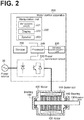
FIG. 2] FIG. 2 is a diagram illustrating a hardware configuration of a motor and a motor control apparatus according to the embodiment. - [
FIG. 3] FIG. 3 is a diagram illustrating a hardware configuration of a communication terminal according to the embodiment and a hardware configuration of a server according to the embodiment. - [
FIG. 4] FIG. 4 is a diagram illustrating a functional block configuration of the motor control system according to the embodiment. - [
FIG. 5] FIG. 5 is a chart illustrating a flow of a bearing lifetime diagnosis performed by the motor control system according to the embodiment. - [
FIG. 6] FIG. 6 is a diagram illustrating a functional block configuration of a motor control system according to another embodiment. - The embodiments will now be described with reference to the accompanying drawings, wherein like reference numerals designate corresponding or identical elements throughout the various drawings.
-
FIG. 1 illustrates a general arrangement of amotor control system 1 according to this embodiment. - As illustrated in
FIG. 1 , themotor control system 1 according to the embodiment includes amotor 100, amotor control apparatus 200, an upper-level controller 300, acommunication terminal 400, and aserver 500. - The
motor 100 is an AC motor driven by themotor control apparatus 200. In themotor 100, bearings 140 (seeFIG. 2 ) are incorporated. Themotor 100 may be any kind of motor insofar as the motor includes thebearings 140, examples including an induction motor, a synchronous reluctance motor, a surface permanent-magnet synchronous motor, and an interior permanent-magnet synchronous motor. Themotor 100 is connected to themotor control apparatus 200 via an electric power line, enabling themotor control apparatus 200 to control themotor 100 to run or stop and to control the rotational speed of themotor 100. - The
motor control apparatus 200 is an apparatus that includes semiconductor switches and, by switching the semiconductor switches, performs conversion of power such as frequency, current, and voltage. Themotor control apparatus 200 receives power from a commercial AC power source or a commercial DC power source, converts the power into variable frequency three-phase AC power, and supplies the AC power to themotor 100. Themotor control apparatus 200 may be an inverter that drives themotor 100 by controlling the number of rotations of themotor 100 in any manner deemed desired. Themotor control apparatus 200 may be a servo controller (servo amplifier) used to drive and control a servo motor used as themotor 100. Themotor control apparatus 200 includes amanipulation unit 220. Themanipulation unit 220 is connected to the body of themotor control apparatus 200, and is used by a user to make various manipulations with respect to themotor control apparatus 200. Themanipulation unit 220 also displays internal states. Themanipulation unit 220 may be a removable keypad. - The upper-
level controller 300 is an apparatus that makes a command to themotor control apparatus 200 to cause themotor control apparatus 200 to make a predetermined operation. The upper-level controller 300 may be a PLC (Programmable Logic Controller). The upper-level controller 300 executes a program set in advance to change a setting value set in themotor control apparatus 200, thereby controlling themotor control apparatus 200. - The
communication terminal 400 is a terminal that is communicable with themotor control apparatus 200 and theserver 500. In this embodiment, thecommunication terminal 400 is a portable device that has a wireless communication function. InFIG. 1 , a smartphone is illustrated as an example of thecommunication terminal 400. Thecommunication terminal 400 may be a terminal other than a smartphone, examples including a PDA terminal, a tablet terminal, and a laptop PC. Thecommunication terminal 400 establishes a wireless connection with themotor control apparatus 200 to display information concerning themotor control apparatus 200 and to execute applications for making various manipulation instructions to themotor control apparatus 200. As a result, thecommunication terminal 400 is able to remotely make various manipulation instructions to themotor control apparatus 200 and remotely display information. - The
server 500 is a network apparatus connected to acommunication network 10. Theserver 500 may be asingle server 500 or include a plurality ofservers 500. Thecommunication network 10 may be a public communication line such as the Internet. In this embodiment, thecommunication network 10 includes a wide-area wireless communication network. Theserver 500 communicates with themotor control apparatus 200 via thecommunication network 10. Theserver 500 may indirectly communicate with themotor control apparatus 200 via thecommunication terminal 400. It is to be noted, however, that the communication between theserver 500 and themotor control apparatus 200 is not made by way of the upper-level controller 300. Theserver 500 may collect information from a large number ofmotor control apparatuses 200, store the information as an accumulation of big data, and perform machine learning using the big data. - A hardware configuration of the
motor control system 1 will be described.FIG. 2 is a diagram illustrating a hardware configuration of themotor 100 and themotor control apparatus 200. InFIG. 2 , an internal structure of themotor 100 is schematically illustrated. - As illustrated in
FIG. 2 , themotor 100 includes astator coil 110, arotor 120, arotation axis 130, and thebearings 140. When power from themotor control apparatus 200 is supplied through thestator coil 110, a rotational magnetic field is formed around thestator coil 110, causing therotor 120 and therotation axis 130 to rotate. Therotation axis 130 transmits the rotational force to another mechanical device. It is to be noted that a load acting in the direction along therotation axis 130 is referred to as thrust load, and a load acting in the direction perpendicular to therotation axis 130 is referred to as radial load. Therotation axis 130 is rotatably held by the pair ofbearings 140. In each of thebearings 140, grease fills the space between the inner ring and the outer ring, and makes the balls in the space smoothly rollable. With this configuration, thebearings 140 rotate with minimized friction. Thebearings 140 may be supplied a lubricant from outside themotor 100. Thebearings 140 are replaceable parts. - The
motor control apparatus 200 includes apower conversion circuit 210, themanipulation unit 220, awireless communication unit 230, aprocessor 240, and astorage 250. - The
power conversion circuit 210 includes semiconductor switches and, by switching the semiconductor switches, converts power from a power source 20 (which is a commercial AC power source or a commercial DC power source) into variable frequency three-phase AC power. Thepower conversion circuit 210 may include: a converter section that converts AC power into DC power; a smoothing circuit section that smoothens the DC power; and an inverter section that converts the smoothened DC power into AC power. Operations of thepower conversion circuit 210 are controlled by theprocessor 240. - The
manipulation unit 220 includes: amanipulation switch 221, which receives various manipulations made by the user for themotor control apparatus 200; and adisplay 222, which outputs images. Themanipulation switch 221 may be integral to thedisplay 222 to form a touch panel display. Themanipulation unit 220 may include aspeaker 223, which outputs sound. - The
wireless communication unit 230 is made up of elements such as an antenna and a communication-purpose controller. Thewireless communication unit 230 establishes a wireless connection with thecommunication terminal 400 to make wireless communication with thecommunication terminal 400. The wireless communication that thewireless communication unit 230 makes with thecommunication terminal 400 complies with a near-field wireless communication standard such as Bluetooth (®) and Wi-Fi (®). Thewireless communication unit 230 may be incorporated in themanipulation unit 220. - The
processor 240 is connected to thepower conversion circuit 210, themanipulation unit 220, thewireless communication unit 230, and thestorage 250, and thus controls the operation of the entirety of themotor control apparatus 200. Theprocessor 240 may be an MPU (Micro-Processing Unit). Theprocessor 240 executes programs stored in thestorage 250 to perform various kinds of processing. - The
storage 250 stores: programs executed by theprocessor 240; and information used in processing performed by theprocessor 240. Thestorage 250 includes a volatile memory and a nonvolatile memory. The volatile memory may be a RAM (Random Access Memory). The nonvolatile memory may be a ROM (Read Only Memory) or an EEPROM (Electrically Erasable Programmable Read Only Memory). -
FIG. 3 is a diagram illustrating a hardware configuration of thecommunication terminal 400 and a hardware configuration of theserver 500. - As illustrated in
FIG. 3 , thecommunication terminal 400 includes a firstwireless communication unit 410, a secondwireless communication unit 420, a user interface 430, astorage 440, and aprocessor 450. The firstwireless communication unit 410 establishes a wireless connection with thecommunication network 10 to make wireless communication with thecommunication network 10. The wireless communication complies with a wide-area wireless communication standard. The secondwireless communication unit 420 establishes a wireless connection with themotor control apparatus 200 to make wireless communication with themotor control apparatus 200. The wireless communication complies with a near-field wireless communication standard. The user interface 430 may include: a manipulation switch that receives various manipulations made by the user; a display that outputs images; a speaker that outputs sound; and a microphone receives sound. The manipulation switch may be integral to the display to form a touch panel display. Thestorage 440 stores: programs executed by theprocessor 450; and information used in processing performed by theprocessor 450. Theprocessor 450 executes the programs stored in thestorage 440 to perform various kinds of processing. - The
server 500 includes acommunication unit 510, astorage 520, and aprocessor 530. Thecommunication unit 510 is connected to thecommunication network 10. Thestorage 520 stores: programs executed by theprocessor 530; and information used in processing performed by theprocessor 530. Theprocessor 530 executes the programs stored in thestorage 520 to perform various kinds of processing. - Next, description will be made with regard to a functional block configuration of the
motor control system 1 associated with lifetime diagnosis of thebearings 140.FIG. 4 is a diagram illustrating a functional block configuration of themotor control system 1. - As illustrated in
FIG. 4 , themotor control system 1 includes themotor control apparatus 200, thecommunication terminal 400, afirst server 500A, asecond server 500B, and athird server 500C. While the following description is regarding an example in which thefirst server 500A, thesecond server 500B, and thethird server 500C are separate from each other, two or more servers may be integrated into one server. - The
motor control apparatus 200 includes adriving time adder 241, a remaininglifetime calculator 242, a remaininglifetime adjuster 243, acomparer 244, awarning outputter 246, a usagecondition information storage 251, anadjustment information storage 252, ahistory information storage 253, and athreshold storage 254. - The
communication terminal 400 includes alifetime setter 451, afirst downloader 452, anuploader 453, and asecond downloader 454. While the following description is regarding an example in which thelifetime setter 451 is provided in thecommunication terminal 451, thelifetime setter 451 may be provided in themotor control apparatus 200. - The
first server 500A includes afirst database 531. Thesecond server 500B includes asecond database 532 and anupdater 533. Thethird server 500C includes athird database 534. - In the
motor control apparatus 200, thedriving time adder 241 adds up the driving time of themotor 100, which is a period of time for which themotor 100 is driven, to obtain an accumulated driving time t. Then, thedriving time adder 241 outputs the accumulated driving time t. Thedriving time adder 241 starts adding up the driving time at the time when themotor 100 starts operating after being installed. Thedriving time adder 241 may stop adding up the driving time while the driving of themotor 100 is suspended. Thedriving time adder 241 may reset the accumulated driving time t at the time when thebearings 140 of themotor 100 are replaced. - In the
communication terminal 400, at the time when, for example, themotor 100 starts operating after being installed, thelifetime setter 451 sets a lifetime T', which is a lifetime unique to eachbearing 140. Thelifetime setter 451 sets the lifetime T', which is a lifetime unique to thebearing 140, based on: a reference lifetime T, which is a lifetime determined according to a specification of thebearing 140; and usage condition information L, which indicates a usage condition for using themotor 100. The reference lifetime T is a rated lifetime ("catalog value") of thebearing 140, that is, a theoretical lifetime of thebearing 140. The usage condition information L includes at least one of a parameter associated with themotor control apparatus 200 and a parameter associated with themotor 100. Example parameters that may be used include thrust load, radial load, load point, bearing size, grease kind, bearing span, motor rotational speed, and motor torque. - The
lifetime setter 451 may obtain the reference lifetime T and the usage condition information L from the usagecondition information storage 251. The usagecondition information storage 251 stores, in advance, information concerning themotor 100, information concerning themotor control apparatus 200, and information input from the user through themanipulation terminal 220. Alternatively, thelifetime setter 451 may obtain the reference lifetime T and the usage condition information L based on information input from the user through thecommunication terminal 400. Thelifetime setter 451 may obtain the reference lifetime T from thefirst database 531. - In the
first server 500A, thefirst database 531 stores a lifetime setting information C(L), which indicates a relationship that the lifetime T' has with the reference lifetime T and the usage condition information L. The lifetime setting information C(L) is a calculation formula or a table for identifying the lifetime T' based on the usage condition information L. Thelifetime setter 451 sets the lifetime T' that has been identified based at least on the usage condition information L and the lifetime setting information C(L). The lifetime setting information C(L) may have such a configuration that as the thrust load and/or radial load increases, the lifetime T' decreases on a large scale as compared with the reference lifetime T. The lifetime setting information C(L) may have such a configuration that as the motor rotational speed and/or the motor torque increases, the lifetime T' decreases on a large scale as compared with the reference lifetime T. For example, the lifetime T' may be calculated by solving the following Formula (1).
- The
lifetime setter 451 may obtain the lifetime setting information C(L) from thefirst server 500A and identify the lifetime T' based on the lifetime setting information C(L) obtained from thefirst server 500A and based on the usage condition information L. In this case, thelifetime setter 451 may provide an ID of themotor 100 to thefirst server 500A so as to obtain the lifetime setting information C(L) from thefirst server 500A. - Alternatively, instead of the
lifetime setter 451 identifying the lifetime T', thefirst server 500A may identify the lifetime T' using at least the usage condition information L and the lifetime setting information C(L). In this case, thelifetime setter 451 provides the reference lifetime T and the usage condition information L to thefirst server 500A so as to obtain the lifetime T' identified by thefirst server 500A. - In the
motor control apparatus 200, the remaininglifetime calculator 242 calculates a remaining lifetime ΔT of thebearing 140 based on the lifetime T' set by thelifetime setter 451 and based on the accumulated driving time t output from thedriving time adder 241. For example, the remaininglifetime calculator 242 subtracts the accumulated driving time t from the lifetime T' as represented by the following Formula (2), thereby calculating the remaining lifetime ΔT.
- In the
motor control apparatus 200, based on a driving result of themotor 100, which is obtained by driving themotor 100, thelifetime adjuster 243 adjusts the remaining lifetime ΔT to a value corresponding to a state unique to thebearing 140. In other words, after themotor 100 starts operating, thelifetime adjuster 243 adjusts the remaining lifetime ΔT based on a state (degradation state) of thebearing 140 that is operating. Thelifetime adjuster 243 may adjust the lifetime T' set by thelifetime setter 451 to indirectly adjust the remaining lifetime ΔT. - The
lifetime adjuster 243 may include afirst adjuster 243a. Thefirst adjuster 243a adjusts the lifetime T' to a value unique to thebearing 140 based on bearing associated information X, which is obtained by an inspection of thebearing 140 and obtained the driving result of themotor 100. When the inspection of thebearings 140 is performed periodically by the user, the user inputs the bearing associated information X into, for example, themanipulation unit 220. Thelifetime adjuster 243 obtains the bearing associated information X input by the user. Examples of the bearing associated information X include oil level (oil gauge), oil quantity and oil flow (oil sight), oil leakage, grease leakage, oil ring normal rotation, bearing sound, temperature, and humidity. Thefirst adjuster 243a adjusts the remaining lifetime ΔT using lifetime adjustment information S(X), which indicates a relationship that the bearing associated information X, which is obtained by the inspection of thebearing 140, has with an adjusted lifetime T". The lifetime adjustment information S(X) is a calculation formula or a table for identifying the adjusted lifetime T" based on the bearing associated information X. The lifetime adjustment information S(X) may have such an example configuration that as the degree of bearing degradation indicated by the bearing associated information X increases, the lifetime T' decreases on a large scale. For example, the adjusted lifetime T" is calculated by solving the following Formula (3).
- For example, an adjusted remaining lifetime ΔT' is calculated by solving the following Formula (4).

- The
lifetime adjuster 243 may also include asecond adjuster 243b. Thesecond adjuster 243b adjusts the lifetime T' to a value unique to thebearing 140 based on a waveform that indicates a driving state of themotor control apparatus 200 and that has been obtained as the driving result of themotor 100. Examples of the driving state of themotor control apparatus 200 include frequency, torque, and current. The waveform indicating the driving state of themotor control apparatus 200 is obtained based on a detection value obtained by a sensor (such as a current sensor and a voltage sensor) provided in thepower conversion circuit 210 of themotor control apparatus 200. Thesecond adjuster 243b adjusts the remaining lifetime ΔT using lifetime adjustment information K(A), which indicates a relationship that the waveform, A, indicating the driving state of themotor control apparatus 200 has with the adjusted lifetime T". The lifetime adjustment information K(A) is a calculation formula or a table for identifying the adjusted lifetime T" based on the waveform A, which indicates the driving state of themotor control apparatus 200. The lifetime adjustment information K(A) may have such an example configuration that as a turbulence (that is, a ripple component) of the waveform indicating the driving state of themotor control apparatus 200 increases, the lifetime T' decreases on a large scale. The adjusted lifetime T" is calculated by solving the above-described Formula (3). The remaining lifetime ΔT' is calculated by solving the above-described Formula (4). - The lifetime adjustment information (S(X) and K(A)) used by the
lifetime adjuster 243 are stored in theadjustment information storage 252. The lifetime adjustment information stored in theadjustment information storage 252 may be updatable by thesecond server 500B via thecommunication terminal 400. Thesecond database 532 of thesecond server 500B stores the lifetime adjustment information (S(X) and K(A)). Each of the information indicates a relationships that the driving result of themotor 100 has with a value corresponding to the state unique to thebearing 140. When thecommunication terminal 400 communicates with themotor control apparatus 200 and finds that the lifetime adjustment information stored in thesecond server 500B is an updated version of the lifetime adjustment information that thelifetime adjuster 243 of themotor control apparatus 200 is using, thecommunication terminal 400 may update the lifetime adjustment information used by thelifetime adjuster 243 to the updated version stored in thesecond server 500B. Specifically, thefirst downloader 452 of thecommunication terminal 400 may compare version information of the lifetime adjustment information stored in theadjustment information storage 252 with version information of the lifetime adjustment information stored in thesecond database 532. When these pieces of version information are different from each other, thefirst downloader 452 may substitute the lifetime adjustment information stored in theadjustment information storage 252 with the lifetime adjustment information downloaded from thesecond database 532. As a result, thelifetime adjuster 243 adjusts the remaining lifetime ΔT based on the updated lifetime adjustment information. - Further, the
second database 532 of thesecond server 500B may be updated by machine learning. When theuploader 453 of thecommunication terminal 400 communicates with themotor control apparatus 200, theuploader 453 uploads, to thesecond server 500B, history information indicating the driving result of themotor 100 accumulating in thehistory information storage 253 of themotor control apparatus 200. Thehistory information storage 253 accumulates the history information until the history information, which indicates the driving result of themotor 100, is uploaded. Theupdater 533 of thesecond server 500B updates the lifetime adjustment information stored in thesecond database 532 by performing learning such as reinforcement learning (for example, knowledge base, statistics base, or neural net base) based on the uploaded history information. - In the
motor control apparatus 200, thecomparer 244 compares the remaining lifetime ΔT' adjusted by the remaininglifetime adjuster 243 with a threshold α. The threshold α may be zero. When the threshold α is zero, thecomparer 244 determines whether the lifetime of thebearing 140 is ended. It is to be noted, however, that when the lifetime of thebearing 140 ends, thebearing 140 may break down, causing an operation failure of themotor 100. Under the circumstances, the threshold α is preferably a value higher than zero. In this embodiment, thethreshold storage 254 stores a threshold α set based on at least one of the kind and the application of themotor 100. Thecomparer 244 compares the remaining lifetime ΔT' with the threshold α stored in thethreshold storage 254. - The threshold α stored in the
threshold storage 254 may be updatable by thethird server 500C via thecommunication terminal 400. Thethird database 534 of thethird server 500C stores a threshold α that is based on the kind and/or the application of themotor 100. When thecommunication terminal 400 communicates with themotor control apparatus 200 and finds that the threshold stored in thethird server 500C is an updated version of the threshold stored in thethreshold storage 254 of themotor control apparatus 200, thecommunication terminal 400 updates the threshold α stored in thethreshold storage 254 to the updated version stored in thethird server 500C. Specifically, thesecond downloader 454 of thecommunication terminal 400 compares version information of the threshold α stored in thethreshold storage 254 with version information of the threshold stored in thethird database 534. When these pieces of version information are different from each other, thesecond downloader 454 substitutes the threshold α stored in theadjustment information storage 254 with the threshold downloaded from thethird database 534. - In the
motor control apparatus 200, when the remaining lifetime ΔT' is equal to or less than the threshold α, thewarning outputter 246 outputs warning information. Thewarning outputter 246 may output the warning information in the form of an image on thedisplay 222 of themanipulation unit 220. Thewarning outputter 246 may output the warning information in the form of sound from thespeaker 223 of themanipulation unit 220. Thewarning outputter 246 may output the warning information to thecommunication terminal 400 via thewireless communication unit 230. The content of the warning information may be any content insofar as the user recognizes a necessity for replacement of thebearing 140. The warning information may include information indicating the remaining lifetime ΔT of thebearing 140. - Thus, the time to replace each bearing 140 can be identified by adding up the driving time of the
motor 100 and calculating the remaining lifetime of thebearing 140 based on the lifetime of thebearing 140 and the accumulated driving time. When the remaining lifetime is equal to or less than the threshold, warning information is output to make the user recognize the time to replace thebearing 140. -
FIG. 5 is a chart illustrating a flow of a bearing lifetime diagnosis performed by themotor control system 1. - As illustrated in
FIG. 5 , at step S11, at the time when, for example, themotor 100 starts operating after being installed, thelifetime setter 451 of thecommunication terminal 400 sets the lifetime T', which is a lifetime unique to thebearing 140. As described above, thelifetime setter 451 sets the lifetime T', which is a lifetime unique to thebearing 140, based on: the reference lifetime T, which is a lifetime determined according to a specification of thebearing 140; and the usage condition information L, which indicates a usage condition for using themotor 100. - At step S 12, the remaining
lifetime calculator 242 of themotor control apparatus 200 calculates the remaining lifetime ΔT of thebearing 140 based on the lifetime T' set by thelifetime setter 451 and based on the accumulated driving time t output from thedriving time adder 241. - At step S13, the
lifetime adjuster 243 of themotor control apparatus 200 adjusts, based on the driving result of themotor 100, the remaining lifetime ΔT to a value corresponding to a state unique to thebearing 140. In other words, after themotor 100 starts operating, thelifetime adjuster 243 adjusts the remaining lifetime ΔT based on a state of thebearing 140 that is operating. - At step S14, the
comparer 244 of themotor control apparatus 200 compares the remaining lifetime ΔT' adjusted by the remaininglifetime adjuster 243 with the threshold α. When the remaining lifetime ΔT' is not equal to or less than the threshold α (step S14: No), the processing returns to step S12. - When the remaining lifetime ΔT' is equal to or less than the threshold α (step S14: Yes), the
warning outputter 246, at step S15, outputs warning information. - The
motor control apparatus 200 includes: the drivingtime adder 241, which adds up the driving time of themotor 100 to obtain an accumulated driving time of themotor 100; the remaininglifetime calculator 242, which calculates the remaining lifetime ΔT of thebearing 140 based on the lifetime T' of thebearing 140 and based on the accumulated driving time t; and thewarning outputter 246, which outputs warning information when the remaining lifetime ΔT' is equal to or less than the threshold α. This configuration ensures that the time to replace thebearing 140 can be identified by themotor control apparatus 200 when themotor control apparatus 200 adds up the driving time of themotor 100 and calculates the remaining lifetime ΔT of thebearing 140 based on the lifetime of thebearing 140 and the accumulated driving time. When the remaining lifetime ΔT' is equal to or less than the threshold α, themotor control apparatus 200 outputs warning information to make the user recognize the time to replace thebearing 140. When a motor breaks down, there can be consequences such as the production line being forced to stop, causing a great loss in productivity, such as degraded production efficiency and decreased tact time. The embodiment, however, eliminates or minimizes such loss by identifying the time to replace thebearing 140. - In this embodiment, the
motor control system 1 may further include thelifetime setter 451. Thelifetime setter 451 sets the lifetime T', which is a lifetime unique to thebearing 140, which is incorporated in themotor 100. Thelifetime setter 451 sets the lifetime T' based on: the reference lifetime T, which is a lifetime determined according to a specification of thebearing 140; and the usage condition information L, which indicates a usage condition for using themotor 100. In this configuration, the lifetime T' of thebearing 140 is calculated with a usage condition for using thebearings 140 taken into consideration. This ensures that the remaining lifetime ΔT is calculated using a more suitable lifetime T'. In this respect, it is not the remaining lifetime ΔT but the lifetime T' of thebearing 140 that is shortened directly depending on a usage condition. With this configuration, a durability of thebearing 140 determined with a usage condition into consideration is reflected in the lifetime T'. This enables the lifetime to be calculated more accurately in that an aging degradation through a normal usage and a degradation unique to a usage condition are distinguished from each other. - In this embodiment, the
motor control system 1 may further include thefirst server 500A, which includes thefirst database 531. Thefirst database 531 stores the lifetime setting information C(L), which indicates a relationship that the lifetime T' has with the reference lifetime T and the usage condition information L. Thelifetime setter 451 may set a lifetime T' that has been identified based at least on the usage condition information L and the lifetime setting information C(L). With this configuration, the database included in thefirst server 500A is used, so that the remaining lifetime ΔT is calculated using a more suitable lifetime T'. Also in this configuration, it is not necessary for themotor control apparatus 200 itself to store various relationships; by an operation as simple as updating the database on thefirst server 500A side, a bearing lifetime diagnosis made suitable for the kind ofmotor 100 used can be performed. - In this embodiment, the
lifetime setter 451 may set the lifetime T' by identifying the lifetime T' based on the lifetime setting information C(L) obtained from thefirst server 500A and based on the usage condition information L. In this configuration, thelifetime setter 451 is provided in thecommunication terminal 400. This eliminates the need for providing the usage condition information L to thefirst server 500A, ensuring that the lifetime T' can be identified based on the lifetime setting information C(L) obtained from thefirst server 500A. As a result, the volume of communication traffic to and from thefirst server 500A is reduced. - In this embodiment, the
lifetime setter 451 may set the lifetime T' by obtaining the lifetime T' itself identified by thefirst server 500A using at least the usage condition information L and the lifetime setting information C(L). In this configuration, thelifetime setter 451 obtains the lifetime T' identified by thefirst server 500A. This reduces the processing load of thelifetime setter 451 as compared with the case where thelifetime setter 451 identifies the lifetime T'. - In this embodiment, the
motor control apparatus 200 may further include thelifetime adjuster 243. Thelifetime adjuster 243 adjusts the remaining lifetime ΔT to a value corresponding to a state unique to thebearing 140. Thelifetime adjuster 243 adjusts the remaining lifetime ΔT based on the driving result of themotor 100, instead of based on the accumulated driving time t. In this configuration, the lifetime T' is adjusted online (after themotor control apparatus 200 starts operating). This ensures that a lifetime diagnosis is performed accurately for each individual bearing based on its degradation state. - In this embodiment, the
motor control system 1 may further include thesecond server 500B, which includes thesecond database 532. Thesecond database 532 stores the lifetime adjustment information, which indicates a relationship that the driving result of themotor 100 has with a value corresponding to state unique to thebearing 140. When thecommunication terminal 400 communicates with themotor control apparatus 200 and finds that the lifetime adjustment information stored in thesecond server 500B is an updated version of the lifetime adjustment information that thelifetime adjuster 243 of themotor control apparatus 200 is using, thecommunication terminal 400 may update the lifetime adjustment information used by thelifetime adjuster 243 to the updated version stored in thesecond server 500B. Thelifetime adjuster 243 may adjust the remaining lifetime ΔT based on the updated lifetime adjustment information. This configuration ensures that the remaining lifetime ΔT is adjusted more appropriately using the database included in thesecond server 500B. This configuration also ensures that when the database on thesecond server 500B side has been updated, the lifetime adjustment information used in themotor control apparatus 200 can be updated via thecommunication terminal 400. Thus, even though themotor control apparatus 200 has no means of communication with thesecond server 500B, the lifetime adjustment information used in themotor control apparatus 200 can be updated to a new state via thecommunication terminal 400. - In this embodiment, when the
communication terminal 400 communicates with themotor control apparatus 200, thecommunication terminal 400 may upload, to thesecond server 500B, the history information, which indicates the driving result of themotor 100 accumulating in themotor control apparatus 200. Thesecond server 500B may further include theupdater 533, which updates the lifetime adjustment information based on the history information. In this configuration, thesecond server 500B updates the lifetime adjustment information based on the history information, which indicates the driving result of themotor 100. This enables thesecond server 500B to perform learning based on the history information, ensuring that the lifetime adjustment information is updated appropriately. - In this embodiment, the
lifetime adjuster 243 may include thefirst adjuster 243a. Thefirst adjuster 243a adjusts the lifetime T' to a value unique to thebearing 140 based on the bearing associated information X, which is obtained by an inspection of thebearing 140 and obtained as the driving result of themotor 100. This configuration ensures that when an inspection of thebearing 140 is performed after themotor control apparatus 200 starts operating, the remaining lifetime ΔT is adjusted appropriately based on the result of the inspection. - In this embodiment, the
lifetime adjuster 243 may include thesecond adjuster 243b. Thesecond adjuster 243b adjusts the lifetime T' to a value unique to thebearing 140 based on the waveform A, which indicates the driving state of themotor control apparatus 200 and which has been obtained as the driving result of themotor 100. This configuration ensures that the remaining lifetime ΔT is adjusted appropriately based on the waveform A, which indicates a driving state of themotor control apparatus 200. - In this embodiment, the
motor control apparatus 200 includes thethreshold storage 254 stores the threshold α, which is set based on at least one of the kind and the application of themotor 100. Thus, the threshold α, which is set based on at least one of the kind and the application of themotor 100, is used. Using such threshold α makes it possible to, on anindividual motor 100 basis, appropriately set how much time prior the warning information should be output before the lifetime of thebearing 140 ends (that is, how much of a safety margin should be secured). - In this embodiment, the
motor control system 1 further includes thethird server 500C, which includes thethird database 534. Thethird database 534 stores a threshold that is based on the kind and the application of the motor. When thecommunication terminal 400 communicates with themotor control apparatus 200 and finds that the threshold stored in thethird server 500C is an updated version of the threshold stored in thethreshold storage 254 of themotor control apparatus 200, thecommunication terminal 400 updates the threshold stored in thethreshold storage 254 to the updated version stored in thethird server 500C. This configuration ensures that the threshold is set appropriately using the database included in thethird server 500C. This configuration also ensures that when the database on thethird server 500C side has been updated, the threshold used in themotor control apparatus 200 can be updated via thecommunication terminal 400. Thus, even though themotor control apparatus 200 has no means of communication with thethird server 500C, the threshold used in themotor control apparatus 200 can be updated to a new state via thecommunication terminal 400. - While the present invention has been described by way of an embodiment, the description and drawings constituting part of the disclosure should not be construed as limiting the present invention. From the disclosure, various alternative embodiments, examples, and operation technologies will be apparent to one of ordinary skill in the art.
- In the above-described embodiment, a portable terminal is described as an example of the
communication terminal 400. Alternatively, thecommunication terminal 400 may be an built-in terminal incorporated in the motor control apparatus 200 (examples including a card terminal and a chip terminal). In this case, the functional blocks of the communication terminal 400 (thelifetime setter 451, thefirst downloader 452, theuploader 453, and the second downloader 454) are provided in themotor control apparatus 200. - Also, the above-described embodiment provided an example in which the
lifetime adjuster 243 adjusts the remaining lifetime ΔT based on the driving result of themotor 100. Alternatively, the adjustment of the remaining lifetime ΔT performed by thelifetime adjuster 243 may be omitted. In this case, thecomparer 244 compares the remaining lifetime ΔT calculated by the remaininglifetime calculator 242 with the threshold α. - Also, the above-described embodiment provided an example in which three servers are used, namely, the first to
third servers 500A to 500C. Alternatively, it is possible to provide a single server with the functions of the first tothird servers 500A to 500C. In this case, the single server includes thefirst database 531, thesecond database 532, theupdater 533, and thethird database 534. - Also, the above-described embodiment provided an example in which the lifetime adjustment information stored in the
second database 532 is updated by machine learning. Alternatively, it is possible to update, in a manner using machine learning similar to the manner in which the lifetime adjustment information is updated, the lifetime setting information C(L) stored in thefirst database 531 and/or the threshold α stored in thethird database 534. - By referring to
FIG. 6 , description will be made with regard to a configuration in which the threshold α stored in thethird database 534 is updated by machine learning. As illustrated inFIG. 6 , themotor control apparatus 200 includes a secondhistory information storage 255. The secondhistory information storage 255 accumulates the history information, which indicates the driving result of themotor 100. Also, thecommunication terminal 400 includes asecond uploader 455. When thecommunication terminal 400 communicates with themotor control apparatus 200, thesecond uploader 455 uploads, to thethird server 500C, the history information, which indicates the driving result of themotor 100, accumulating in the secondhistory information storage 255 of themotor control apparatus 200. Thethird server 500C includes asecond updater 535. Based on the uploaded history information, thesecond updater 535 updates the threshold α stored in thethird database 534 by performing learning such as reinforcement learning (for example, knowledge base, statistics base, or neural net base) Specifically, thesecond updater 535 collects and learns a history of failures for each kind of themotor 100 and for each application of themotor 100, and updates the threshold α based on the result of the learning. Examples of the history of failures include: "environment information such as temperature and humidity" at the time when a failure occurred (including timings before and after the time); and/or "driving conditions such as a speed value, a current value, a torque value, and/or a command". Also, remaining lifetimes ΔT corresponding to the respective environment information and/or driving conditions may be used. - 1 ... Motor control system, 100 ... Motor, 110 ... Stator coil, 120 ... Rotor, 130 ... Rotation axis, 140 ... Bearing, 200 ... Motor control apparatus, 210 ... Power conversion circuit, 220 ... Manipulation unit, 230 ... Wireless communication unit, 240 ... Processor, 241 ... Driving time adder, 242 ... Remaining lifetime calculator, 243 ... Remaining lifetime adjuster, 244 ... Comparer, 246 ... Warning outputter, 250 ... Storage, 251 ... Usage condition information storage, 252 ... Adjustment information storage, 253 ... History information storage, 254 ... Threshold storage, 300 ... Upper-level controller, 400 ... Communication terminal, 410 ... First wireless communication unit, 420 ... Second wireless communication unit, 430 ... User interface, 440 ... Storage, 450 ... Processor, 451 ... Lifetime setter, 452 ... First downloader, 453 ... Uploader, 454 ... Second downloader, 500 ... Server, 500A ... First server, 500B ... Second server, 500C ... Third server, 510 ... Communication unit, 520 ... Storage, 530 ... Processor, 531 ... First database, 532 ... Second database, 533 ... Updater, 534 ... Third database
Claims (15)
- A motor control system, characterized by:a motor in which a bearing is incorporated; anda motor control apparatus configured to control the motor, the motor control apparatus comprising:a driving time adder configured to add up a driving time of the motor to obtain an accumulated driving time of the motor;a remaining lifetime calculator configured to calculate a remaining lifetime of the bearing based on a lifetime of the bearing and the accumulated driving time; anda warning outputter configured to output warning information when the remaining lifetime is equal to or less than a threshold.
- The motor control system according to claim 1, further comprising:
a lifetime setter configured to, based on a reference lifetime determined according to a specification of the bearing and based on usage condition information indicating a usage condition for using the motor, the lifetime of the bearing incorporated in the motor such that the lifetime is unique to the bearing. - The motor control system according to claim 2, further comprising:a first server comprising a first database storing lifetime setting information indicating a relationship that the lifetime has with the reference lifetime and the usage condition information,wherein the lifetime setter is configured to set the lifetime when the lifetime has been identified based at least on the usage condition information and the lifetime setting information.
- The motor control system according to claim 3, wherein in setting the lifetime, the lifetime setter is configured to identify the lifetime based on the lifetime setting information obtained from the first server and based on the usage condition information.
- The motor control system according to claim 3, wherein in setting the lifetime, the lifetime setter is configured to obtain the lifetime such that the lifetime has been identified by the first server using at least the usage condition information and the lifetime setting information.
- The motor control system according to any one of claims 1 to 5, wherein the motor control apparatus further comprises a lifetime adjuster configured to, based on a driving result of the motor obtained by driving the motor instead of based on the accumulated driving time, adjust the remaining lifetime to a value corresponding to a state unique to the bearing.
- The motor control system according to claim 6, further comprising:a second server comprising a second database storing lifetime adjustment information indicating a relationship that the driving result of the motor has with the value corresponding to the state unique to the bearing; anda terminal communicable with the second server and the motor control apparatus,wherein when the terminal communicates with the motor control apparatus and finds that the lifetime adjustment information stored in the second server is an updated version of the lifetime adjustment information that the lifetime adjuster of the motor control apparatus is using, the terminal is configured to update the lifetime adjustment information used by the lifetime adjuster to the updated version stored in the second server, and the lifetime adjuster is configured to adjust the remaining lifetime based on the updated version.
- The motor control system according to claim 7,
wherein when the terminal communicates with the motor control apparatus, the terminal is configured to upload, to the second server, history information indicating the driving result of the motor accumulating in the motor control apparatus, and
wherein the second server further comprises an updater configured to update the lifetime adjustment information based on the history information. - The motor control system according to any one of claims 6 to 8, wherein the lifetime adjuster comprises a first adjuster configured to adjust the lifetime to a value unique to the bearing based on bearing associated information obtained by an inspection of the bearing and obtained as the driving result of the motor.
- The motor control system according to any one of claims 6 to 9, wherein the lifetime adjuster comprises a second adjuster configured to adjust the lifetime to a value unique to the bearing based on a waveform that indicates a driving state of the motor control apparatus and that has been obtained as the driving result of the motor.
- (The threshold is set based on motor kind and motor application)
The motor control system according to any one of claims 1 to 10, wherein the motor control apparatus comprises a threshold storage storing the threshold such that the threshold is set based on at least one of a kind of the motor and an application of the motor. - The motor control system according to claim 11, further comprising:a third server comprising a third database storing the threshold that is based on the kind of the motor and the application of the motor; anda terminal communicable with the third server and the motor control apparatus,wherein when the terminal communicates with the motor control apparatus and finds that the threshold stored in the third server is an updated version of the threshold stored in the threshold storage of the motor control apparatus, the terminal is configured to update the threshold stored in the threshold storage to the updated version stored in the third server.
- The motor control system according to claim 12,
wherein when the terminal communicates with the motor control apparatus, the terminal is configured to upload, to the third server, history information indicating a driving result of the motor accumulating in the motor control apparatus, and
wherein the third server further comprises an updater configured to update the threshold based on the history information. - A motor control apparatus configured to control a motor in which a bearing is incorporated, characterized by:a driving time adder configured to add up a driving time of the motor to obtain an accumulated driving time of the motor;a remaining lifetime calculator configured to calculate a remaining lifetime of the bearing based on a lifetime of the bearing and the accumulated driving time; anda warning outputter configured to output warning information when the remaining lifetime is equal to or less than a threshold.
- A bearing lifetime diagnosis method, characterized by:using a motor control apparatus configured to control a motor in which a bearing is incorporated, adding up a driving time of the motor to obtain an accumulated driving time of the motor;using the motor control apparatus, calculating a remaining lifetime of the bearing based on a lifetime of the bearing and the accumulated driving time; andusing the motor control apparatus, outputting warning information when the remaining lifetime is equal to or less than a threshold.
Applications Claiming Priority (1)
| Application Number | Priority Date | Filing Date | Title |
|---|---|---|---|
| PCT/JP2018/006202 WO2019163020A1 (en) | 2018-02-21 | 2018-02-21 | Motor control system, motor control device, and bearing life diagnosis method |
Publications (2)
| Publication Number | Publication Date |
|---|---|
| EP3758219A1 true EP3758219A1 (en) | 2020-12-30 |
| EP3758219A4 EP3758219A4 (en) | 2021-11-03 |
Family
ID=67212102
Family Applications (1)
| Application Number | Title | Priority Date | Filing Date |
|---|---|---|---|
| EP18906840.6A Withdrawn EP3758219A4 (en) | 2018-02-21 | 2018-02-21 | ENGINE CONTROL SYSTEM, ENGINE CONTROL DEVICE AND DIAGNOSTIC PROCEDURES FOR BEARING LIFE |
Country Status (5)
| Country | Link |
|---|---|
| US (1) | US11398789B2 (en) |
| EP (1) | EP3758219A4 (en) |
| JP (1) | JP6540911B1 (en) |
| CN (1) | CN111684710A (en) |
| WO (1) | WO2019163020A1 (en) |
Cited By (1)
| Publication number | Priority date | Publication date | Assignee | Title |
|---|---|---|---|---|
| EP4162600B1 (en) * | 2020-08-19 | 2024-06-12 | Siemens Aktiengesellschaft | Software based condition monitoring for machines |
Families Citing this family (7)
| Publication number | Priority date | Publication date | Assignee | Title |
|---|---|---|---|---|
| DE102019209605A1 (en) | 2019-07-01 | 2021-01-07 | Aktiebolaget Skf | Device for detecting a defect in a rotating assembly |
| DE102019209606A1 (en) * | 2019-07-01 | 2021-01-07 | Aktiebolaget Skf | Device for detecting a defect in a rotating assembly |
| CN114600367A (en) * | 2019-11-01 | 2022-06-07 | 三菱电机株式会社 | Motor inductance measuring device, motor drive system and motor inductance measuring method |
| JP7473738B2 (en) * | 2021-03-22 | 2024-04-23 | 株式会社安川電機 | Motor control system, motor control device, and remaining life estimation method |
| JP7718154B2 (en) * | 2021-08-06 | 2025-08-05 | 富士電機株式会社 | Diagnostic device, power conversion device, diagnostic method, and program |
| CN113900020B (en) * | 2021-08-20 | 2024-03-12 | 合众新能源汽车股份有限公司 | New energy automobile driving motor service life estimation method and device and electronic equipment |
| CN114094791A (en) * | 2021-10-26 | 2022-02-25 | 徐州统一电机有限公司 | High-precision brushless direct current motor |
Family Cites Families (15)
| Publication number | Priority date | Publication date | Assignee | Title |
|---|---|---|---|---|
| JP2001350510A (en) * | 2000-06-06 | 2001-12-21 | Mori Seiki Co Ltd | Machine tool maintenance management system |
| JP2003090868A (en) * | 2001-09-19 | 2003-03-28 | Konica Corp | Life estimation device and life estimation method |
| JP3880455B2 (en) * | 2002-05-31 | 2007-02-14 | 中国電力株式会社 | Rolling bearing remaining life diagnosis method and remaining life diagnosis apparatus |
| JP4197474B2 (en) * | 2003-07-10 | 2008-12-17 | 株式会社神戸製鋼所 | Electric screw compressor |
| WO2005038613A2 (en) * | 2003-10-17 | 2005-04-28 | Hydralift Amclyde, Inc. | Equipment component monitoring and replacement management system |
| JP4645879B2 (en) | 2004-03-19 | 2011-03-09 | 株式会社安川電機 | motor |
| DE102005032720B4 (en) * | 2005-07-13 | 2007-04-05 | Siemens Ag | Interface module device for an electric machine for calculating the service life of a bearing |
| JP2007032712A (en) * | 2005-07-27 | 2007-02-08 | Nachi Fujikoshi Corp | Motor bearing deterioration monitoring device and control system |
| JP4791804B2 (en) * | 2005-11-14 | 2011-10-12 | 日機装株式会社 | Motor bearing wear monitoring system |
| US8294403B2 (en) * | 2009-09-04 | 2012-10-23 | Haas Automation, Inc. | Methods and systems for determining and displaying a time to overload of machine tools |
| JP5644374B2 (en) * | 2010-10-27 | 2014-12-24 | 株式会社ジェイテクト | Machine tool spindle state detection device |
| EP2690516A4 (en) * | 2011-03-22 | 2016-03-23 | Ntn Toyo Bearing Co Ltd | Method for diagnosing reusability of mechanical component |
| JP5674859B2 (en) * | 2013-05-16 | 2015-02-25 | ファナック株式会社 | A numerical controller with a function to estimate the life of the bearing that supports the spindle |
| JP2017058137A (en) | 2015-09-14 | 2017-03-23 | Kyb株式会社 | controller |
| JP2018004473A (en) * | 2016-07-04 | 2018-01-11 | ファナック株式会社 | Mechanical learning device for learning estimated life of bearing, life estimation device, and mechanical learning method |
-
2018
- 2018-02-21 JP JP2018552892A patent/JP6540911B1/en active Active
- 2018-02-21 WO PCT/JP2018/006202 patent/WO2019163020A1/en not_active Ceased
- 2018-02-21 CN CN201880088064.8A patent/CN111684710A/en active Pending
- 2018-02-21 EP EP18906840.6A patent/EP3758219A4/en not_active Withdrawn
-
2020
- 2020-08-20 US US16/997,942 patent/US11398789B2/en active Active
Cited By (1)
| Publication number | Priority date | Publication date | Assignee | Title |
|---|---|---|---|---|
| EP4162600B1 (en) * | 2020-08-19 | 2024-06-12 | Siemens Aktiengesellschaft | Software based condition monitoring for machines |
Also Published As
| Publication number | Publication date |
|---|---|
| JP6540911B1 (en) | 2019-07-10 |
| EP3758219A4 (en) | 2021-11-03 |
| US11398789B2 (en) | 2022-07-26 |
| WO2019163020A1 (en) | 2019-08-29 |
| CN111684710A (en) | 2020-09-18 |
| JPWO2019163020A1 (en) | 2020-02-27 |
| US20200382036A1 (en) | 2020-12-03 |
Similar Documents
| Publication | Publication Date | Title |
|---|---|---|
| US11398789B2 (en) | Motor control system, motor control apparatus, and bearing lifetime diagnosis method | |
| CN106485343B (en) | Rote learning device and method, life predication apparatus and electric motor system | |
| US10008903B2 (en) | Energy storage management system | |
| US11556484B2 (en) | Minimizing energy consumption by peripheral machines | |
| EP2190097B1 (en) | Method for operating an energy storage system | |
| CN112015147B (en) | Method, device, system and computer readable medium for debugging and status monitoring | |
| US11087920B2 (en) | System and method for transformer control | |
| JP2012043421A (en) | Maintenance optimization method and system | |
| CN104374571A (en) | Bearing life determination device | |
| CN113657693A (en) | A predictive maintenance system and method for intelligent manufacturing equipment | |
| US10401813B2 (en) | Electrical drive system with model predictive control of a mechanical variable | |
| JP6609520B2 (en) | Microgrid control apparatus and method | |
| US20230246581A1 (en) | Software based condition monitoring for machines | |
| CN107076119B (en) | Wind power plant is by shutting down the reduction operation of wind turbine | |
| CN116128059B (en) | Digital twin-based motor energy consumption inference | |
| US10640124B2 (en) | Drive process recognition and optimization | |
| KR101521771B1 (en) | Method of life assessment diagnosis for high voltage motors | |
| JP2015133290A (en) | Cooling system, and control device and control method of the same | |
| CN113765995A (en) | Wireless communication for industrial automation | |
| US20260029489A1 (en) | System and method for monitoring motor winding degradation | |
| CN118517038A (en) | Fluid supply system, fluid supply device, maintenance method of fluid supply system, and maintenance method of fluid supply device | |
| JP2023176974A (en) | Management device, management method, management program and management system | |
| CN119183638A (en) | Method and system for monitoring an electric machine | |
| WO2022201250A1 (en) | Motor control system, motor control device, and remaining lifespan estimation method | |
| JP2015039259A (en) | Power converter |
Legal Events
| Date | Code | Title | Description |
|---|---|---|---|
| STAA | Information on the status of an ep patent application or granted ep patent |
Free format text: STATUS: THE INTERNATIONAL PUBLICATION HAS BEEN MADE |
|
| PUAI | Public reference made under article 153(3) epc to a published international application that has entered the european phase |
Free format text: ORIGINAL CODE: 0009012 |
|
| STAA | Information on the status of an ep patent application or granted ep patent |
Free format text: STATUS: REQUEST FOR EXAMINATION WAS MADE |
|
| 17P | Request for examination filed |
Effective date: 20200908 |
|
| AK | Designated contracting states |
Kind code of ref document: A1 Designated state(s): AL AT BE BG CH CY CZ DE DK EE ES FI FR GB GR HR HU IE IS IT LI LT LU LV MC MK MT NL NO PL PT RO RS SE SI SK SM TR |
|
| AX | Request for extension of the european patent |
Extension state: BA ME |
|
| DAV | Request for validation of the european patent (deleted) | ||
| DAX | Request for extension of the european patent (deleted) | ||
| A4 | Supplementary search report drawn up and despatched |
Effective date: 20211005 |
|
| RIC1 | Information provided on ipc code assigned before grant |
Ipc: F16C 41/00 20060101ALI20210929BHEP Ipc: H02P 29/00 20160101AFI20210929BHEP |
|
| GRAP | Despatch of communication of intention to grant a patent |
Free format text: ORIGINAL CODE: EPIDOSNIGR1 |
|
| STAA | Information on the status of an ep patent application or granted ep patent |
Free format text: STATUS: GRANT OF PATENT IS INTENDED |
|
| INTG | Intention to grant announced |
Effective date: 20230509 |
|
| STAA | Information on the status of an ep patent application or granted ep patent |
Free format text: STATUS: THE APPLICATION IS DEEMED TO BE WITHDRAWN |
|
| 18D | Application deemed to be withdrawn |
Effective date: 20230920 |