EP3758196B1 - Motor winding connector ring - Google Patents
Motor winding connector ring Download PDFInfo
- Publication number
- EP3758196B1 EP3758196B1 EP20174733.4A EP20174733A EP3758196B1 EP 3758196 B1 EP3758196 B1 EP 3758196B1 EP 20174733 A EP20174733 A EP 20174733A EP 3758196 B1 EP3758196 B1 EP 3758196B1
- Authority
- EP
- European Patent Office
- Prior art keywords
- termination
- coupling member
- stator
- winding
- electrically insulating
- Prior art date
- Legal status (The legal status is an assumption and is not a legal conclusion. Google has not performed a legal analysis and makes no representation as to the accuracy of the status listed.)
- Active
Links
Images





Classifications
-
- H—ELECTRICITY
- H02—GENERATION; CONVERSION OR DISTRIBUTION OF ELECTRIC POWER
- H02K—DYNAMO-ELECTRIC MACHINES
- H02K1/00—Details of the magnetic circuit
- H02K1/06—Details of the magnetic circuit characterised by the shape, form or construction
- H02K1/12—Stationary parts of the magnetic circuit
-
- H—ELECTRICITY
- H02—GENERATION; CONVERSION OR DISTRIBUTION OF ELECTRIC POWER
- H02K—DYNAMO-ELECTRIC MACHINES
- H02K3/00—Details of windings
- H02K3/46—Fastening of windings on the stator or rotor structure
- H02K3/52—Fastening salient pole windings or connections thereto
- H02K3/521—Fastening salient pole windings or connections thereto applicable to stators only
- H02K3/522—Fastening salient pole windings or connections thereto applicable to stators only for generally annular cores with salient poles
-
- H—ELECTRICITY
- H02—GENERATION; CONVERSION OR DISTRIBUTION OF ELECTRIC POWER
- H02K—DYNAMO-ELECTRIC MACHINES
- H02K3/00—Details of windings
- H02K3/02—Windings characterised by the conductor material
-
- H—ELECTRICITY
- H02—GENERATION; CONVERSION OR DISTRIBUTION OF ELECTRIC POWER
- H02K—DYNAMO-ELECTRIC MACHINES
- H02K3/00—Details of windings
- H02K3/04—Windings characterised by the conductor shape, form or construction, e.g. with bar conductors
- H02K3/28—Layout of windings or of connections between windings
-
- H—ELECTRICITY
- H02—GENERATION; CONVERSION OR DISTRIBUTION OF ELECTRIC POWER
- H02K—DYNAMO-ELECTRIC MACHINES
- H02K3/00—Details of windings
- H02K3/32—Windings characterised by the shape, form or construction of the insulation
- H02K3/38—Windings characterised by the shape, form or construction of the insulation around winding heads, equalising connectors, or connections thereto
-
- H—ELECTRICITY
- H02—GENERATION; CONVERSION OR DISTRIBUTION OF ELECTRIC POWER
- H02K—DYNAMO-ELECTRIC MACHINES
- H02K3/00—Details of windings
- H02K3/46—Fastening of windings on the stator or rotor structure
- H02K3/50—Fastening of winding heads, equalising connectors, or connections thereto
-
- H—ELECTRICITY
- H02—GENERATION; CONVERSION OR DISTRIBUTION OF ELECTRIC POWER
- H02K—DYNAMO-ELECTRIC MACHINES
- H02K5/00—Casings; Enclosures; Supports
- H02K5/04—Casings or enclosures characterised by the shape, form or construction thereof
- H02K5/22—Auxiliary parts of casings not covered by groups H02K5/06-H02K5/20, e.g. shaped to form connection boxes or terminal boxes
- H02K5/225—Terminal boxes or connection arrangements
-
- B—PERFORMING OPERATIONS; TRANSPORTING
- B60—VEHICLES IN GENERAL
- B60K—ARRANGEMENT OR MOUNTING OF PROPULSION UNITS OR OF TRANSMISSIONS IN VEHICLES; ARRANGEMENT OR MOUNTING OF PLURAL DIVERSE PRIME-MOVERS IN VEHICLES; AUXILIARY DRIVES FOR VEHICLES; INSTRUMENTATION OR DASHBOARDS FOR VEHICLES; ARRANGEMENTS IN CONNECTION WITH COOLING, AIR INTAKE, GAS EXHAUST OR FUEL SUPPLY OF PROPULSION UNITS IN VEHICLES
- B60K6/00—Arrangement or mounting of plural diverse prime-movers for mutual or common propulsion, e.g. hybrid propulsion systems comprising electric motors and internal combustion engines
- B60K6/20—Arrangement or mounting of plural diverse prime-movers for mutual or common propulsion, e.g. hybrid propulsion systems comprising electric motors and internal combustion engines the prime-movers consisting of electric motors and internal combustion engines, e.g. HEVs
- B60K6/22—Arrangement or mounting of plural diverse prime-movers for mutual or common propulsion, e.g. hybrid propulsion systems comprising electric motors and internal combustion engines the prime-movers consisting of electric motors and internal combustion engines, e.g. HEVs characterised by apparatus, components or means specially adapted for HEVs
- B60K6/26—Arrangement or mounting of plural diverse prime-movers for mutual or common propulsion, e.g. hybrid propulsion systems comprising electric motors and internal combustion engines the prime-movers consisting of electric motors and internal combustion engines, e.g. HEVs characterised by apparatus, components or means specially adapted for HEVs characterised by the motors or the generators
-
- B—PERFORMING OPERATIONS; TRANSPORTING
- B60—VEHICLES IN GENERAL
- B60Y—INDEXING SCHEME RELATING TO ASPECTS CROSS-CUTTING VEHICLE TECHNOLOGY
- B60Y2200/00—Type of vehicle
- B60Y2200/90—Vehicles comprising electric prime movers
- B60Y2200/91—Electric vehicles
-
- B—PERFORMING OPERATIONS; TRANSPORTING
- B60—VEHICLES IN GENERAL
- B60Y—INDEXING SCHEME RELATING TO ASPECTS CROSS-CUTTING VEHICLE TECHNOLOGY
- B60Y2200/00—Type of vehicle
- B60Y2200/90—Vehicles comprising electric prime movers
- B60Y2200/92—Hybrid vehicles
-
- B—PERFORMING OPERATIONS; TRANSPORTING
- B60—VEHICLES IN GENERAL
- B60Y—INDEXING SCHEME RELATING TO ASPECTS CROSS-CUTTING VEHICLE TECHNOLOGY
- B60Y2400/00—Special features of vehicle units
- B60Y2400/60—Electric Machines, e.g. motors or generators
-
- H—ELECTRICITY
- H02—GENERATION; CONVERSION OR DISTRIBUTION OF ELECTRIC POWER
- H02K—DYNAMO-ELECTRIC MACHINES
- H02K2203/00—Specific aspects not provided for in the other groups of this subclass relating to the windings
- H02K2203/09—Machines characterised by wiring elements other than wires, e.g. bus rings, for connecting the winding terminations
Definitions
- the present invention relates to a stator assembly for an electric motor.
- a rotating magnetic field is generated within the motor's stator assembly, resulting in rotation of the motor's rotor assembly.
- the rotating magnetic field is generated by a plurality of circumferentially distributed windings that are mounted within a plurality of circumferentially distributed stator slots and teeth.
- the windings which may be comprised of round or rectangular wire, are divided into coil groups, each of which represents a single pole of a single phase.
- Each phase of the coil windings terminate into a connector, commonly referred to as a lug, which is used to couple the coil windings to an AC power source.
- a lug which is used to couple the coil windings to an AC power source.
- stator manufacturing process In a typical stator manufacturing process, distributing the windings within the stator assembly is a rapid process utilizing an automated CNC (computer numerical control) winding machine. Once the stator windings are completed, they must be coupled to the stator lugs. During this portion of the stator manufacturing process the wire bundles are routed, insulation sleeves are added, and the lugs are resistance welded to the wire bundles. As this portion of the process is performed by hand, it is quite slow and adds considerable expense to the stator assembly. Accordingly, what is needed is a stator manufacturing process that minimizes or eliminates the need for manually performing the final steps associated with coupling the windings to the lugs, thereby providing a more cost effective stator assembly. The present invention provides a system and manufacturing process that achieves these goals while also providing a more versatile stator assembly that may be configured to meet a variety of torque and power requirements.
- CNC computer numerical control
- DE 10 2016 114723 A1 discloses an electrical, essentially ringshaped connection device for a stator of an electric motor with a retracted round wire winding, comprising: an electrically insulating base ring ; an electrically conductive star ring resting thereon and having a plurality of radially outwardly extending outer connection contacts; three structurally identical pairs, each having a lower, electrically insulating intermediate ring and an upper electrically conductive connection ring resting thereon with outer connection contacts extending radially outward and with one extending from its radially inner side in the axial direction upwardly extending, upper connection contact; and a substantially annular cover which covers the upper connection ring, from which the three upper connection contacts of the electrically conductive connection rings protrude upwards and which covers the outer connection contacts radially outwards; wherein the three pairs of electrically insulating intermediate rings and electrically conductive connection rings are arranged offset from one another in the circumferential direction so that their outer connection contacts are each at connection positions spaced from one
- WO 2018/179790 A1 discloses a phase busbar unit provided with: a busbar holder made of an insulator and supporting a plurality of phase busbars of a motor that rotates around the center axis thereof; and a busbar cover made of an insulator and fixed to the busbar holder while covering at least one axial side of each of the busbars.
- Each of the busbars includes: a base part; a plurality of extension parts extending radially outward from the base part; and terminals provided on radially outer end portions of the extension parts.
- the busbar cover includes a plurality of protrusion parts protruding toward the other axial side, wherein the plurality of the protrusion parts contact the busbars, and at least one of the protrusion parts contacts the base part in the vicinity of the extension parts.
- EP 2 824 765 A1 discloses wire connection member for connecting a first wire to a second wire by crimping includes a partition for dividing a first housing space for housing tip portions of the first wire from a second housing space for housing a tip portion of the second wire, a first housing portion that, together with the partition, forms the first housing space, and a second housing portion that, together with the partition, forms the second housing space.
- the partition is arranged between the first and second housing portions.
- WO 2011/108734 A1 discloses a busbar unit which is arranged on an axial end portion of a stator, and electrically connected with a plurality of coil wire terminals arranged to project in an axial direction above the axial end portion of the stator.
- the busbar unit includes a plurality of busbars each including a body portion defined by an electrically conductive wire shaped in a ring or the letter "C", the body portion being arranged around an axis of the stator; a holder member arranged on the axial end portion of the stator to hold the busbars; and a plurality of terminal members each including a busbar connection portion connected with the body portion of one of the busbars, and a coil connection portion connected with one of the coil wire terminals.
- each termination coupling member of each termination coupling member group may be (i) laser welded, (ii) TIG welded, (iii) resistance welded, and/or (iv) brazed to a different winding termination of the plurality of winding terminations during attachment of the pre-fabricated connector to the stator.
- each of the plurality of electrically insulating coupling member overlays may include a U-shaped end portion that is configured to partially surround a corresponding winding termination, and which may be crimped onto the corresponding winding termination during attachment of the pre-fabricated connector to the stator.
- the pre-fabricated connector as fabricated may further include a second plurality of termination coupling members divided into a second plurality of termination coupling member groups, where each termination coupling member of each termination coupling member group of the second plurality of termination coupling member groups is configured to be mechanically and conductively coupled to a different winding termination of the plurality of winding terminations, where each termination coupling member group of the second plurality of termination coupling member groups is mechanically and conductively coupled to one of a plurality of lugless bus bars, and where the electrically insulating material is configured to prevent electrical contact or partial discharge between the plurality of lugless bus bars, and to prevent electrical contact or partial discharge between the plurality of bus bars and the plurality of lugless bus bars.
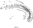
- Fig. 4 provides a perspective view of the electrically conductive connector portion 400 of connector 300.
- Fig. 5 provides a rear perspective view of connector portion 400.
- Bus bars 501-503 are connected to lugs 325-327, respectively.
- each bus bar 501-503 is connected to four winding terminations.
- bus bar 503 and therefore lug 327 is connected to termination coupling members 301-304 which, in turn, are connected to winding terminations 101-104 when the connector is attached to the stator windings.
Landscapes
- Engineering & Computer Science (AREA)
- Power Engineering (AREA)
- Insulation, Fastening Of Motor, Generator Windings (AREA)
- Manufacture Of Motors, Generators (AREA)
Description
- The present invention relates to a stator assembly for an electric motor.
- In response to the demands of consumers who are driven both by ever-escalating fuel prices and the dire consequences of global warming, the automobile industry is slowly starting to embrace the need for ultra-low emission, high efficiency cars. While some within the industry are attempting to achieve these goals by engineering more efficient internal combustion engines, others are incorporating hybrid or all-electric drivetrains into their vehicle line-ups. To meet consumer expectations, however, the automobile industry must not only achieve a greener drivetrain, but must do so while maintaining reasonable levels of performance, range, reliability, safety and cost.
- In recent years, electric vehicles have proven to be not only environmentally friendly, but also capable of meeting, if not exceeding, consumer desires and expectations regarding performance. While early electric vehicles used DC motors in order to achieve the variable levels of speed and torque required to drive a vehicle, the advent of modern motor control systems utilizing direct torque control have allowed AC motors to deliver the same level of performance while providing the many benefits associated with AC motors including small size, low cost, high reliability and low maintenance.
- In an AC motor a rotating magnetic field is generated within the motor's stator assembly, resulting in rotation of the motor's rotor assembly. The rotating magnetic field is generated by a plurality of circumferentially distributed windings that are mounted within a plurality of circumferentially distributed stator slots and teeth. The windings, which may be comprised of round or rectangular wire, are divided into coil groups, each of which represents a single pole of a single phase. Each phase of the coil windings terminate into a connector, commonly referred to as a lug, which is used to couple the coil windings to an AC power source. Thus, for example, in a typical three phase stator assembly there are three winding lugs that connect the stator windings to the three phases of an AC inverter.
- In a typical stator manufacturing process, distributing the windings within the stator assembly is a rapid process utilizing an automated CNC (computer numerical control) winding machine. Once the stator windings are completed, they must be coupled to the stator lugs. During this portion of the stator manufacturing process the wire bundles are routed, insulation sleeves are added, and the lugs are resistance welded to the wire bundles. As this portion of the process is performed by hand, it is quite slow and adds considerable expense to the stator assembly. Accordingly, what is needed is a stator manufacturing process that minimizes or eliminates the need for manually performing the final steps associated with coupling the windings to the lugs, thereby providing a more cost effective stator assembly. The present invention provides a system and manufacturing process that achieves these goals while also providing a more versatile stator assembly that may be configured to meet a variety of torque and power requirements.
-
US 2016/036187 A1 discloses a stator assembly according to the preamble of claim 1. - Furthermore,
DE 10 2016 114723 A1 discloses an electrical, essentially ringshaped connection device for a stator of an electric motor with a retracted round wire winding, comprising: an electrically insulating base ring ; an electrically conductive star ring resting thereon and having a plurality of radially outwardly extending outer connection contacts; three structurally identical pairs, each having a lower, electrically insulating intermediate ring and an upper electrically conductive connection ring resting thereon with outer connection contacts extending radially outward and with one extending from its radially inner side in the axial direction upwardly extending, upper connection contact; and a substantially annular cover which covers the upper connection ring, from which the three upper connection contacts of the electrically conductive connection rings protrude upwards and which covers the outer connection contacts radially outwards; wherein the three pairs of electrically insulating intermediate rings and electrically conductive connection rings are arranged offset from one another in the circumferential direction so that their outer connection contacts are each at connection positions spaced from one another in the circumferential direction and that their upper connection contacts are at Circumferentially spaced contact positions lie. - Additionally,
WO 2018/179790 A1 discloses a phase busbar unit provided with: a busbar holder made of an insulator and supporting a plurality of phase busbars of a motor that rotates around the center axis thereof; and a busbar cover made of an insulator and fixed to the busbar holder while covering at least one axial side of each of the busbars. Each of the busbars includes: a base part; a plurality of extension parts extending radially outward from the base part; and terminals provided on radially outer end portions of the extension parts. The busbar cover includes a plurality of protrusion parts protruding toward the other axial side, wherein the plurality of the protrusion parts contact the busbars, and at least one of the protrusion parts contacts the base part in the vicinity of the extension parts. - Moreover,
EP 2 824 765 A1 discloses wire connection member for connecting a first wire to a second wire by crimping includes a partition for dividing a first housing space for housing tip portions of the first wire from a second housing space for housing a tip portion of the second wire, a first housing portion that, together with the partition, forms the first housing space, and a second housing portion that, together with the partition, forms the second housing space. The partition is arranged between the first and second housing portions. - In addition,
WO 2011/108734 A1 discloses a busbar unit which is arranged on an axial end portion of a stator, and electrically connected with a plurality of coil wire terminals arranged to project in an axial direction above the axial end portion of the stator. The busbar unit includes a plurality of busbars each including a body portion defined by an electrically conductive wire shaped in a ring or the letter "C", the body portion being arranged around an axis of the stator; a holder member arranged on the axial end portion of the stator to hold the busbars; and a plurality of terminal members each including a busbar connection portion connected with the body portion of one of the busbars, and a coil connection portion connected with one of the coil wire terminals. - The present invention provides a stator assembly as claimed in claim 1.
- In one aspect, each termination coupling member of each termination coupling member group may be (i) laser welded, (ii) TIG welded, (iii) resistance welded, and/or (iv) brazed to a different winding termination of the plurality of winding terminations during attachment of the pre-fabricated connector to the stator.
- In another aspect, each of the plurality of electrically insulating coupling member overlays may include a U-shaped end portion that is configured to partially surround a corresponding winding termination, and which may be crimped onto the corresponding winding termination during attachment of the pre-fabricated connector to the stator.
- In another aspect, the pre-fabricated connector as fabricated may further include a second plurality of termination coupling members divided into a second plurality of termination coupling member groups, where each termination coupling member of each termination coupling member group of the second plurality of termination coupling member groups is configured to be mechanically and conductively coupled to a different winding termination of the plurality of winding terminations, where each termination coupling member group of the second plurality of termination coupling member groups is mechanically and conductively coupled to one of a plurality of lugless bus bars, and where the electrically insulating material is configured to prevent electrical contact or partial discharge between the plurality of lugless bus bars, and to prevent electrical contact or partial discharge between the plurality of bus bars and the plurality of lugless bus bars. Each termination coupling member of each termination coupling member group may be (i) laser welded, (ii) TIG welded, (iii) resistance welded, and/or (iv) brazed to a different winding termination of the plurality of winding terminations during attachment of the pre-fabricated connector to the stator. The plurality of electrically insulating coupling member overlays may be configured to prevent electrical contact or partial discharge between the second plurality of termination coupling members, and between the first and second pluralities of termination coupling members. Each of the plurality of electrically insulating coupling member overlays may include a U-shaped end portion that is configured to partially surround a corresponding winding termination, and which may be crimped onto the corresponding winding termination during attachment of the pre-fabricated connector to the stator.
- In another aspect, the first plurality of termination coupling members and the plurality of bus bars may be fabricated from a copper material.
- In another aspect, at least a portion of the plurality of bus bars may be over-molded with the electrically insulating material (e.g., plastic) to form the pre-fabricated connector.
- In another aspect, the plurality of windings may be comprised of (i) copper wire with a round cross-section, or (ii) copper wire with a rectangular cross-section.
- In another aspect, each bus bar of the plurality of bus bars may correspond to a phase of the electric motor.
- A further understanding of the nature and advantages of the present invention may be realized by reference to the remaining portions of the specification and the drawings.
- It should be understood that the accompanying figures are only meant to illustrate, not limit, the scope of the invention and should not be considered to be to scale. Additionally, the same reference label on different figures should be understood to refer to the same component or a component of similar functionality.
-
Fig. 1 provides a perspective view of a stator, this view highlighting the stator winding terminations; -
Fig. 2 provides a detailed perspective view of a portion of the stator shown inFig. 1 ; -
Fig. 3 provides a perspective view of a connector designed in accordance with the invention; -
Fig. 4 provides a perspective view of the electrically conductive connector portion of the connector shown inFig. 3 ; -
Fig. 5 provides a rear perspective view of the electrically conductive portion of the connector shown inFig. 3 ; -
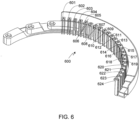
Fig. 6 provides a perspective view of the electrically insulating portion of the connector shown inFig. 3 ; -
Fig. 7 provides a perspective view of an alternate electrically insulating portion that is equally applicable to the connector shown inFig. 3 ; -
Fig. 8 provides a perspective view of a stator assembly that utilizes the stator shown inFig. 1 and the connector shown inFig. 3 ; and -
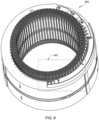
Fig. 9 provides a detailed perspective view of a portion of the stator assembly shown inFig. 8 . - As used herein, the singular forms "a", "an" and "the" are intended to include the plural forms as well, unless the context clearly indicates otherwise. The terms "comprises", "comprising", "includes", and/or "including", as used herein, specify the presence of stated features, integers, steps, operations, elements, and/or components, but do not preclude the presence or addition of one or more other features, integers, steps, operations, elements, components, and/or groups thereof. As used herein, the term "and/or" and the symbol "/" are meant to include any and all combinations of one or more of the associated listed items. Additionally, while the terms first, second, etc. may be used herein to describe various steps or calculations, these steps or calculations should not be limited by these terms, rather these terms are only used to distinguish one step or calculation from another. For example, a first calculation could be termed a second calculation; similarly a first step could be termed a second step; similarly a first component could be termed a second component, all without departing from the scope of this disclosure.
- The stator assembly described and illustrated herein is generally designed for use in a vehicle utilizing an electric motor, e.g., an electric vehicle (EV), although it should be understood that it is equally applicable to electric motors designed for use in other applications. As used herein, the terms "electric vehicle" and "EV" are interchangeable and may refer to an all-electric vehicle, a plug-in hybrid vehicle, also referred to as a PHEV, or a hybrid vehicle, also referred to as a HEV, where a hybrid vehicle utilizes multiple sources of propulsion including an electric drive system.
- The stator assembly of the present invention provides a connector that simplifies the process of connecting the wire windings of the stator to the stator lugs. The connector is preferably used with a stator in which the stator windings terminate in a relatively small number of terminations, and preferably in which those winding terminations are adjacent or in close proximity to one another.
-
Fig. 1 provides a perspective view of anexemplary stator 100 that may be used with the connector. As shown, the windings ofstator 100 terminate in 24 terminals 101-124. Additionally and as preferred, winding terminations 101-124 are immediately adjacent to one another as shown, thereby simplifying their connection to the connector described below.Fig. 2 provides a detailed perspective view ofportion 125 ofstator 100. -
Fig. 3 provides a perspective view of aconnector 300 comprised of an electrically conductive connector portion, preferably fabricated from copper, which couples to winding terminations 101-124 via termination coupling members 301-324. In the present exemplary embodiment, and as described further below, the conductive connector portion couples a first subset of the stator winding terminations to lug 325; a second subset of the stator winding terminations to lug 326; and a third subset of the stator winding terminations to lug 327. Additionally, and as described further below, the conductive connector portion ofconnector 300 also performs the function of the central node for four sets of winding circuits. -
Fig. 4 provides a perspective view of the electricallyconductive connector portion 400 ofconnector 300.Fig. 5 provides a rear perspective view ofconnector portion 400. As shown inFigs. 4 and5 , in this configuration there are seven bus bars 501-507. Bus bars 501-503 are connected to lugs 325-327, respectively. In this embodiment, each bus bar 501-503 is connected to four winding terminations. For example and as shown,bus bar 503 and therefore lug 327 is connected to termination coupling members 301-304 which, in turn, are connected to winding terminations 101-104 when the connector is attached to the stator windings. Thus for this aspect of the illustrated connector, termination coupling members 301-304 form an electrically conductive link betweenlug 327 and stator winding terminations 101-104. Each bus bar 504-507 is lugless (i.e., does not include a connecting lug) and is connected to three winding terminations and thus acts as the central node of the corresponding winding circuits. For example, in thefigures bus bar 504 is shown connected totermination coupling members terminations - In addition to the electrically
conductive portion 400,connector 300 includes an electrically insulating portion.Fig. 6 provides a perspective view of electrically insulatingportion 600. As shown inFigs. 3 and6 , electrically insulatingportion 600 is configured to separate bus bars 501-507 from each other, and to prevent termination coupling members 301-324 from inadvertently shorting to the wrong bus bar. Preferably insulatingportion 600 is formed by inserting electricallyconductive connector portion 400 into a plastic injection mold andover-molding portion 400 with a suitable electrically insulating plastic such as a thermosetting polyester material or an engineered thermoplastic (e.g., polypropylene). - In the embodiment of the electrically insulating
portion 600 shown inFig. 6 , a plurality of insulating coupling member overlays 601-624 are provided that correspond to, and partially surround, corresponding termination coupling members 301-324. As a result of the approximately U-shaped design of each coupling member overlay, an electrically insulating barrier is provided between adjacent termination coupling members. Additionally, at least a portion of each overlay may be configured to extend beyond the sides of the corresponding winding termination, thereby further simplifying connector alignment relative to the stator winding terminations. In at least one embodiment, each overlay is sized such that it may be pinched or crimped onto the corresponding winding termination, thus helping to hold each coupling member to its corresponding winding termination during the process of attaching the connector to the stator windings. - It should be understood that the connector does not require the inclusion of insulating coupling member overlays (e.g., overlays 601-624). For example,
Fig. 7 provides a perspective view of an alternate electrically insulatingportion 700, equally applicable to the electricallyconductive portion 400 ofconnector 300. As shown, this example electrically insulates bus bars 501-507 from one another but does not include the insulating coupling member overlays. - After fabrication of
connector 300, it is placed on top ofstator assembly 100 such that each of the winding terminations (e.g., terminations 101-124) are aligned with, and in contact with, the corresponding termination coupling members (e.g., coupling members 301-324).Fig. 8 provides a perspective view ofconnector 300 attached tostator 100.Fig. 9 provides a detailed perspective view ofportion 801 ofstator assembly 800. Note that in the embodiment illustrated inFigs. 8 and9 , the connector utilizes the insulating member shown inFig. 6 that includes insulating coupling member overlays 601-624. As previously noted, while overlays 601-624 may aid during the connector alignment process, these overlays are not required. - Once
connector 300 and termination coupling members 301-324 are properly positioned relative to winding terminations 101-124, each winding termination is then permanently coupled to the corresponding termination coupling member. Preferably the winding terminations are attached to the corresponding termination coupling members by laser welding. Alternately, tungsten inert gas (TIG) welding, resistance welding or brazing may be used to attach each termination coupling member to the corresponding winding termination. As previously noted, in at least onepreferred embodiment connector 300 includes the approximately U-shaped coupling member overlays (e.g., overlays 601-624). In addition to electrically insulating adjacent winding terminations and adjacent winding coupling members, the termination coupling member overlays simplify connector alignment and can aid during the connector attachment process. - The connector offers a number of advantages over conventional techniques for connecting the stator windings of a motor to the coupling lugs. First and foremost, since the connector is designed to be fabricated as a separate component and then attached to the stator windings via a relatively quick process, a process that can be automated, the resultant stator assembly can be rapidly fabricated and at a lower cost. Thus the slow and tedious process of connecting the winding terminations to the stator lugs is replaced with a rapid manufacturing process that can be automated. Second, different connectors that couple the winding terminations to the bus bars in different configurations can be used to achieve different motor torque and power characteristics for the same set of stator windings. Similarly, different connectors can be used to alter the number of phases for a particular stator winding configuration, for example switching the number of phases from three to six. Third, the connector is very compact, thereby allowing the connector assembly to have minimal impact on the overall stator assembly diameter and length. Fourth, the connector is equally applicable to windings fabricated from round or rectangular wire.
- Systems and methods have been described in general terms as an aid to understanding details of the invention. In some instances, well-known structures, materials, and/or operations have not been specifically shown or described in detail to avoid obscuring aspects of the invention. In other instances, specific details have been given in order to provide a thorough understanding of the invention. Therefore the disclosures and descriptions herein are intended to be illustrative, but not limiting, of the scope of the invention.
Claims (14)
- A stator assembly for an electric motor, comprising:a stator (100) with a plurality of windings circumferentially distributed about said stator (100), wherein said plurality of windings terminate in a plurality of winding terminations (101-124); anda pre-fabricated connector (300) attached to said stator (100) via said plurality of winding terminations (101-124), said pre-fabricated connector (300) fabricated prior to attachment to said stator (100), said pre-fabricated connector (300) as fabricated comprising:a first plurality of termination coupling members (301-304, 309-312, 317-320) divided into a first plurality of termination coupling member groups, wherein each termination coupling member of each termination coupling member group of said first plurality of termination coupling member groups is configured to be mechanically and conductively coupled to a different winding termination of said plurality of winding terminations (101-124), wherein each termination coupling member group is mechanically and conductively coupled to one of a plurality of bus bars (501-503), and wherein each bus bar of said plurality of bus bars (501-503) includes an independent lug (325-327); andan electrically insulating material (600) overlaying portions of said plurality of bus bars (501-503), said electrically insulating material (600) configured to prevent contact between said plurality of bus bars (501-503);characterized bya plurality of electrically insulating coupling member overlays (601-624), said plurality of electrically insulating coupling member overlays (601-624) configured to prevent contact between said first plurality of termination coupling members (301-304, 309-312, 317-320).
- The stator assembly of claim 1, wherein each termination coupling member (301-304, 309-312, 317-320) of each termination coupling member group of said first plurality of termination coupling member groups is (i) laser welded, (ii) tungsten inert gas (TIG) welded, (iii) resistance welded, or (iv) brazed to said different winding termination of said plurality of winding terminations (101-124) during attachment of said pre-fabricated connector (300) to said stator (100).
- The stator assembly of claim 1, each of said plurality of electrically insulating coupling member overlays (601-624) further comprising a U-shaped portion configured to partially surround a corresponding winding termination of said plurality of winding terminations (101-124).
- The stator assembly of claim 3, wherein each U-shaped portion is crimped onto said corresponding winding termination during attachment of said pre-fabricated connector (300) to said stator (100).
- The stator assembly of any claim of claims 1-4, said pre-fabricated connector (300) as fabricated further comprising a second plurality of termination coupling members (305-308, 313-316, 321-324) divided into a second plurality of termination coupling member groups, wherein each termination coupling member of each termination coupling member group of said second plurality of termination coupling member groups is configured to be mechanically and conductively coupled to a different winding termination of said plurality of winding terminations (101-124), wherein each termination coupling member group of said second plurality of termination coupling member groups is mechanically and conductively coupled to one of a plurality of lugless bus bars (504-507), said electrically insulating material (600) configured to prevent contact between said plurality of lugless bus bars (504-507), and said electrically insulating material (600) configured to prevent contact between said plurality of bus bars (501-503) and said plurality of lugless bus bars (504-507).
- The stator assembly of claim 5, wherein each termination coupling member (301-304, 309-312, 317-320) of each termination coupling member group of said first plurality of termination coupling member groups is (i) laser welded, (ii) tungsten inert gas (TIG) welded, (iii) resistance welded, or (iv) brazed to said different winding termination of said plurality of winding terminations (101-124) during attachment of said pre-fabricated connector (300) to said stator (100), and wherein each termination coupling member (305-308, 313-316, 321-324) of each termination coupling member group of said second plurality of termination coupling member groups is laser welded to said different winding termination of said plurality of winding terminations (101-124) during attachment of said pre-fabricated connector (300) to said stator (100).
- The stator assembly of claim 5, wherein said plurality of electrically insulating coupling member overlays (601-624) are configured to prevent contact between said second plurality of termination coupling members (305-308, 313-316, 321-324), and wherein said plurality of electrically insulating coupling member overlays (601-624) are configured to prevent contact between said first plurality of termination coupling members (301-304, 309-312, 317-320) and said second plurality of termination coupling members (305-308, 313-316, 321-324).
- The stator assembly of claim 7, each of said plurality of electrically insulating coupling member overlays (601-624) further comprising a U-shaped portion configured to partially surround a corresponding winding termination of said plurality of winding terminations (101-124).
- The stator assembly of claim 8, wherein each U-shaped portion is crimped onto said corresponding winding termination during attachment of said pre-fabricated connector (300) to said stator (100).
- The stator assembly of any claim of claims 1-9, wherein each of said first plurality of termination coupling members (301-304, 309-312, 317-320) is fabricated from a copper material, and wherein each of said plurality of bus bars (501-503) is fabricated from said copper material.
- The stator assembly of any claim of claims 1-10, wherein at least a portion of said plurality of bus bars (501-503) are over-molded with said electrically insulating material (600).
- The stator assembly of any claim of claims 1-11, wherein a plastic material is selected as said electrically insulating material (600) used to form said pre-fabricated connector (300).
- The stator assembly of any claim of claims 1-12, said plurality of windings comprised of copper wire with a round or rectangular cross-section.
- The stator assembly of any claim of claims 1-13, wherein each bus bar of said plurality of bus bars (501-503) corresponds to a phase of said electric motor.
Applications Claiming Priority (1)
| Application Number | Priority Date | Filing Date | Title |
|---|---|---|---|
| US16/453,029 US11133719B2 (en) | 2019-06-26 | 2019-06-26 | Motor winding connector ring |
Publications (2)
| Publication Number | Publication Date |
|---|---|
| EP3758196A1 EP3758196A1 (en) | 2020-12-30 |
| EP3758196B1 true EP3758196B1 (en) | 2025-07-02 |
Family
ID=70736757
Family Applications (1)
| Application Number | Title | Priority Date | Filing Date |
|---|---|---|---|
| EP20174733.4A Active EP3758196B1 (en) | 2019-06-26 | 2020-05-14 | Motor winding connector ring |
Country Status (5)
| Country | Link |
|---|---|
| US (1) | US11133719B2 (en) |
| EP (1) | EP3758196B1 (en) |
| JP (2) | JP7041999B2 (en) |
| KR (1) | KR102386600B1 (en) |
| CN (2) | CN213341768U (en) |
Families Citing this family (8)
| Publication number | Priority date | Publication date | Assignee | Title |
|---|---|---|---|---|
| US11165301B2 (en) * | 2019-11-12 | 2021-11-02 | Borgwarner Inc. | Interior bus bar for electric machine winding |
| FR3121801B1 (en) | 2021-04-07 | 2023-05-05 | Nidec Psa Emotors | Connector for rotating electrical machine stator |
| US12244197B2 (en) | 2021-07-14 | 2025-03-04 | Borgwarner Inc. | Stator with outer diameter bus bar connection |
| EP4447285A4 (en) * | 2021-12-16 | 2025-03-19 | Guangdong Welling Motor Manufacturing Co., Ltd. | MOTOR, POWER ASSEMBLY AND ELECTRIC-ASSISTED BICYCLE |
| US12456893B2 (en) | 2022-08-29 | 2025-10-28 | Atieva, Inc. | Electric motor with unvarnished end winding for stator |
| DE102022123902B4 (en) * | 2022-09-19 | 2025-05-15 | Schaeffler Technologies AG & Co. KG | Modular system for manufacturing a stator for an electrical machine |
| WO2024216262A1 (en) | 2023-04-14 | 2024-10-17 | Garner Development Services, Llc | Caseless electric motor with a stationary shaft for marine enviroments |
| WO2024227054A1 (en) | 2023-04-27 | 2024-10-31 | Garner Development Services, Llc | Jet pump propulsion system |
Family Cites Families (20)
| Publication number | Priority date | Publication date | Assignee | Title |
|---|---|---|---|---|
| JP3700236B2 (en) | 1996-03-01 | 2005-09-28 | 松下電器産業株式会社 | Electric motor |
| JP2000134851A (en) | 1998-10-20 | 2000-05-12 | Matsushita Electric Ind Co Ltd | Motor stator |
| US20030214190A1 (en) | 2002-05-15 | 2003-11-20 | Delco Remy America | Connection device for hairpin wound electric machines |
| US7187095B2 (en) * | 2004-02-24 | 2007-03-06 | Asmo Co., Ltd. | Motor, control circuit member and manufacturing method of motor |
| JP2008125170A (en) | 2006-11-09 | 2008-05-29 | Toyota Motor Corp | Rotating electric machine and processing method of lead wire terminal thereof |
| JP4855239B2 (en) * | 2006-12-25 | 2012-01-18 | 三菱電線工業株式会社 | Insulation housing for motor |
| JP4939244B2 (en) | 2007-01-31 | 2012-05-23 | アイチエレック株式会社 | Winding connection device for rotating machine, stator for rotating machine and rotating machine |
| JP2008219972A (en) * | 2007-02-28 | 2008-09-18 | Jtekt Corp | Electric motor |
| JP2010011627A (en) | 2008-06-26 | 2010-01-14 | Asmo Co Ltd | Bus bar, bus bar apparatus, stator coupling body, brushless motor, and manufacturing method of stator coupling body |
| JP4688910B2 (en) * | 2008-08-08 | 2011-05-25 | 三菱電機株式会社 | Electric power steering motor |
| US8497617B2 (en) * | 2009-07-15 | 2013-07-30 | GM Global Technology Operations LLC | Stators with improved conductor assembly and method of making same |
| JP5703604B2 (en) | 2010-03-03 | 2015-04-22 | 日本電産株式会社 | Bus bar unit and motor |
| US20130076175A1 (en) | 2011-09-22 | 2013-03-28 | Paul F. Turnbull | Connection module for a bar wound stator assembly and method of manufacturing a bar wound stator assembly |
| JP6190599B2 (en) * | 2013-03-08 | 2017-08-30 | Kyb株式会社 | Manufacturing method of bus bar unit |
| JP6024609B2 (en) | 2013-07-09 | 2016-11-16 | 日立金属株式会社 | Power collection and distribution ring |
| JP6260358B2 (en) | 2014-03-07 | 2018-01-17 | 日産自動車株式会社 | Power distribution member of concentrated winding motor |
| DE112016000451T5 (en) | 2015-01-22 | 2017-11-09 | Jtekt Corporation | Electric motor unit and drive unit for a vehicle |
| DE102016204935A1 (en) | 2016-03-24 | 2017-09-28 | Robert Bosch Gmbh | Circuit board for a stator of an electrical machine and method for manufacturing an electrical machine |
| DE102016114723A1 (en) | 2016-08-09 | 2018-02-15 | Scherdel Innotec Forschungs- Und Entwicklungs-Gmbh | Electrical, substantially annular connection device for a stator of an electric motor and electric motor |
| DE112018001656T5 (en) | 2017-03-31 | 2020-01-02 | Nidec Corporation | Busbar unit and motor that has it |
-
2019
- 2019-06-26 US US16/453,029 patent/US11133719B2/en active Active
-
2020
- 2020-05-13 JP JP2020084796A patent/JP7041999B2/en active Active
- 2020-05-13 KR KR1020200056861A patent/KR102386600B1/en active Active
- 2020-05-14 EP EP20174733.4A patent/EP3758196B1/en active Active
- 2020-06-04 CN CN202021009536.7U patent/CN213341768U/en not_active Expired - Fee Related
- 2020-06-04 CN CN202010498790.6A patent/CN112152336B/en active Active
-
2022
- 2022-03-09 JP JP2022036212A patent/JP7554393B2/en active Active
Also Published As
| Publication number | Publication date |
|---|---|
| JP7041999B2 (en) | 2022-03-25 |
| JP2021005998A (en) | 2021-01-14 |
| EP3758196A1 (en) | 2020-12-30 |
| US20200412195A1 (en) | 2020-12-31 |
| JP7554393B2 (en) | 2024-09-20 |
| CN112152336A (en) | 2020-12-29 |
| CN112152336B (en) | 2023-11-07 |
| US11133719B2 (en) | 2021-09-28 |
| KR20210001913A (en) | 2021-01-06 |
| JP2022091796A (en) | 2022-06-21 |
| CN213341768U (en) | 2021-06-01 |
| KR102386600B1 (en) | 2022-04-15 |
Similar Documents
| Publication | Publication Date | Title |
|---|---|---|
| EP3758196B1 (en) | Motor winding connector ring | |
| US11545867B2 (en) | Bus bar assembly for electric machine winding | |
| US11557934B2 (en) | Interior bus bar for electric machine winding | |
| EP1739809B1 (en) | A central power distributing member for a brushless motor, a brushless motor provided therewith and a method of assembling it | |
| JP5978357B2 (en) | Rotating electric machine | |
| US8143752B2 (en) | Electric motor having electrical connecting elements for connection to winding leads | |
| US8497618B2 (en) | Stator for rotatry electrical machine including an insulating bobbin | |
| CN107431405B (en) | stator | |
| US7205689B2 (en) | Electric motor with space-saving low-resistance neutral ring | |
| US8067867B2 (en) | Motor with neutral bus ring connecting multiple motor coils | |
| CN103368304A (en) | In-vehicle motor and electric power steering device including the same | |
| US10938256B2 (en) | Motor stator and manufacturing method thereof | |
| CN103683618A (en) | Distribution part and rotary electric machine | |
| US10033238B2 (en) | Connection ring arrangement for an electrical machine | |
| CA2349237A1 (en) | Device for converting electric energy into a mechanical one and/or for doing the opposite and method for producing such a device | |
| JP2007174869A (en) | Insulator, stator assembly, segment stator, and stator for rotating electrical machine | |
| KR101000621B1 (en) | Automotive Motor Generator | |
| JP2006187164A (en) | Rotating electric machine | |
| CN115149671A (en) | Stator and motor | |
| CN220692477U (en) | Busbar and driving system | |
| KR102350229B1 (en) | Terminal assembly for drive motor | |
| JP2002233095A (en) | Electric equipment | |
| US20260088665A1 (en) | Wave winding ring terminal high voltage connection |
Legal Events
| Date | Code | Title | Description |
|---|---|---|---|
| PUAI | Public reference made under article 153(3) epc to a published international application that has entered the european phase |
Free format text: ORIGINAL CODE: 0009012 |
|
| STAA | Information on the status of an ep patent application or granted ep patent |
Free format text: STATUS: REQUEST FOR EXAMINATION WAS MADE |
|
| 17P | Request for examination filed |
Effective date: 20200514 |
|
| AK | Designated contracting states |
Kind code of ref document: A1 Designated state(s): AL AT BE BG CH CY CZ DE DK EE ES FI FR GB GR HR HU IE IS IT LI LT LU LV MC MK MT NL NO PL PT RO RS SE SI SK SM TR |
|
| AX | Request for extension of the european patent |
Extension state: BA ME |
|
| P01 | Opt-out of the competence of the unified patent court (upc) registered |
Effective date: 20230707 |
|
| GRAP | Despatch of communication of intention to grant a patent |
Free format text: ORIGINAL CODE: EPIDOSNIGR1 |
|
| STAA | Information on the status of an ep patent application or granted ep patent |
Free format text: STATUS: GRANT OF PATENT IS INTENDED |
|
| RIC1 | Information provided on ipc code assigned before grant |
Ipc: H02K 3/50 20060101AFI20241231BHEP |
|
| INTG | Intention to grant announced |
Effective date: 20250127 |
|
| GRAS | Grant fee paid |
Free format text: ORIGINAL CODE: EPIDOSNIGR3 |
|
| GRAA | (expected) grant |
Free format text: ORIGINAL CODE: 0009210 |
|
| STAA | Information on the status of an ep patent application or granted ep patent |
Free format text: STATUS: THE PATENT HAS BEEN GRANTED |
|
| AK | Designated contracting states |
Kind code of ref document: B1 Designated state(s): AL AT BE BG CH CY CZ DE DK EE ES FI FR GB GR HR HU IE IS IT LI LT LU LV MC MK MT NL NO PL PT RO RS SE SI SK SM TR |
|
| REG | Reference to a national code |
Ref country code: GB Ref legal event code: FG4D |
|
| REG | Reference to a national code |
Ref country code: CH Ref legal event code: EP |
|
| REG | Reference to a national code |
Ref country code: DE Ref legal event code: R096 Ref document number: 602020053653 Country of ref document: DE |
|
| REG | Reference to a national code |
Ref country code: IE Ref legal event code: FG4D |
|
| REG | Reference to a national code |
Ref country code: NL Ref legal event code: MP Effective date: 20250702 |
|
| PG25 | Lapsed in a contracting state [announced via postgrant information from national office to epo] |
Ref country code: PT Free format text: LAPSE BECAUSE OF FAILURE TO SUBMIT A TRANSLATION OF THE DESCRIPTION OR TO PAY THE FEE WITHIN THE PRESCRIBED TIME-LIMIT Effective date: 20251103 |
|
| PG25 | Lapsed in a contracting state [announced via postgrant information from national office to epo] |
Ref country code: NL Free format text: LAPSE BECAUSE OF FAILURE TO SUBMIT A TRANSLATION OF THE DESCRIPTION OR TO PAY THE FEE WITHIN THE PRESCRIBED TIME-LIMIT Effective date: 20250702 |
|
| REG | Reference to a national code |
Ref country code: AT Ref legal event code: MK05 Ref document number: 1810415 Country of ref document: AT Kind code of ref document: T Effective date: 20250702 |
|
| PG25 | Lapsed in a contracting state [announced via postgrant information from national office to epo] |
Ref country code: IS Free format text: LAPSE BECAUSE OF FAILURE TO SUBMIT A TRANSLATION OF THE DESCRIPTION OR TO PAY THE FEE WITHIN THE PRESCRIBED TIME-LIMIT Effective date: 20251102 |
|
| PG25 | Lapsed in a contracting state [announced via postgrant information from national office to epo] |
Ref country code: NO Free format text: LAPSE BECAUSE OF FAILURE TO SUBMIT A TRANSLATION OF THE DESCRIPTION OR TO PAY THE FEE WITHIN THE PRESCRIBED TIME-LIMIT Effective date: 20251002 |
|
| REG | Reference to a national code |
Ref country code: LT Ref legal event code: MG9D |
|
| PG25 | Lapsed in a contracting state [announced via postgrant information from national office to epo] |
Ref country code: AT Free format text: LAPSE BECAUSE OF FAILURE TO SUBMIT A TRANSLATION OF THE DESCRIPTION OR TO PAY THE FEE WITHIN THE PRESCRIBED TIME-LIMIT Effective date: 20250702 |
|
| PG25 | Lapsed in a contracting state [announced via postgrant information from national office to epo] |
Ref country code: FI Free format text: LAPSE BECAUSE OF FAILURE TO SUBMIT A TRANSLATION OF THE DESCRIPTION OR TO PAY THE FEE WITHIN THE PRESCRIBED TIME-LIMIT Effective date: 20250702 |
|
| PG25 | Lapsed in a contracting state [announced via postgrant information from national office to epo] |
Ref country code: HR Free format text: LAPSE BECAUSE OF FAILURE TO SUBMIT A TRANSLATION OF THE DESCRIPTION OR TO PAY THE FEE WITHIN THE PRESCRIBED TIME-LIMIT Effective date: 20250702 |
|
| PG25 | Lapsed in a contracting state [announced via postgrant information from national office to epo] |
Ref country code: GR Free format text: LAPSE BECAUSE OF FAILURE TO SUBMIT A TRANSLATION OF THE DESCRIPTION OR TO PAY THE FEE WITHIN THE PRESCRIBED TIME-LIMIT Effective date: 20251003 |
|
| PG25 | Lapsed in a contracting state [announced via postgrant information from national office to epo] |
Ref country code: CZ Free format text: LAPSE BECAUSE OF FAILURE TO SUBMIT A TRANSLATION OF THE DESCRIPTION OR TO PAY THE FEE WITHIN THE PRESCRIBED TIME-LIMIT Effective date: 20250702 Ref country code: SE Free format text: LAPSE BECAUSE OF FAILURE TO SUBMIT A TRANSLATION OF THE DESCRIPTION OR TO PAY THE FEE WITHIN THE PRESCRIBED TIME-LIMIT Effective date: 20250702 |
|
| PG25 | Lapsed in a contracting state [announced via postgrant information from national office to epo] |
Ref country code: LV Free format text: LAPSE BECAUSE OF FAILURE TO SUBMIT A TRANSLATION OF THE DESCRIPTION OR TO PAY THE FEE WITHIN THE PRESCRIBED TIME-LIMIT Effective date: 20250702 |
|
| PG25 | Lapsed in a contracting state [announced via postgrant information from national office to epo] |
Ref country code: PL Free format text: LAPSE BECAUSE OF FAILURE TO SUBMIT A TRANSLATION OF THE DESCRIPTION OR TO PAY THE FEE WITHIN THE PRESCRIBED TIME-LIMIT Effective date: 20250702 Ref country code: BG Free format text: LAPSE BECAUSE OF FAILURE TO SUBMIT A TRANSLATION OF THE DESCRIPTION OR TO PAY THE FEE WITHIN THE PRESCRIBED TIME-LIMIT Effective date: 20250702 |
|
| PG25 | Lapsed in a contracting state [announced via postgrant information from national office to epo] |
Ref country code: RS Free format text: LAPSE BECAUSE OF FAILURE TO SUBMIT A TRANSLATION OF THE DESCRIPTION OR TO PAY THE FEE WITHIN THE PRESCRIBED TIME-LIMIT Effective date: 20251002 |
|
| PG25 | Lapsed in a contracting state [announced via postgrant information from national office to epo] |
Ref country code: ES Free format text: LAPSE BECAUSE OF FAILURE TO SUBMIT A TRANSLATION OF THE DESCRIPTION OR TO PAY THE FEE WITHIN THE PRESCRIBED TIME-LIMIT Effective date: 20250702 |
|
| REG | Reference to a national code |
Ref country code: DE Ref legal event code: R082 Ref document number: 602020053653 Country of ref document: DE Representative=s name: GULDE & PARTNER PATENT- UND RECHTSANWALTSKANZL, DE |
|
| PG25 | Lapsed in a contracting state [announced via postgrant information from national office to epo] |
Ref country code: SM Free format text: LAPSE BECAUSE OF FAILURE TO SUBMIT A TRANSLATION OF THE DESCRIPTION OR TO PAY THE FEE WITHIN THE PRESCRIBED TIME-LIMIT Effective date: 20250702 |
|
| PG25 | Lapsed in a contracting state [announced via postgrant information from national office to epo] |
Ref country code: DK Free format text: LAPSE BECAUSE OF FAILURE TO SUBMIT A TRANSLATION OF THE DESCRIPTION OR TO PAY THE FEE WITHIN THE PRESCRIBED TIME-LIMIT Effective date: 20250702 |
|
| PG25 | Lapsed in a contracting state [announced via postgrant information from national office to epo] |
Ref country code: IT Free format text: LAPSE BECAUSE OF FAILURE TO SUBMIT A TRANSLATION OF THE DESCRIPTION OR TO PAY THE FEE WITHIN THE PRESCRIBED TIME-LIMIT Effective date: 20250702 |
|
| PG25 | Lapsed in a contracting state [announced via postgrant information from national office to epo] |
Ref country code: SK Free format text: LAPSE BECAUSE OF FAILURE TO SUBMIT A TRANSLATION OF THE DESCRIPTION OR TO PAY THE FEE WITHIN THE PRESCRIBED TIME-LIMIT Effective date: 20250702 Ref country code: EE Free format text: LAPSE BECAUSE OF FAILURE TO SUBMIT A TRANSLATION OF THE DESCRIPTION OR TO PAY THE FEE WITHIN THE PRESCRIBED TIME-LIMIT Effective date: 20250702 |