EP3758194A1 - Rotor für eine elektrische maschine, elektrische maschine für ein fahrzeug und fahrzeug - Google Patents
Rotor für eine elektrische maschine, elektrische maschine für ein fahrzeug und fahrzeug Download PDFInfo
- Publication number
- EP3758194A1 EP3758194A1 EP20180288.1A EP20180288A EP3758194A1 EP 3758194 A1 EP3758194 A1 EP 3758194A1 EP 20180288 A EP20180288 A EP 20180288A EP 3758194 A1 EP3758194 A1 EP 3758194A1
- Authority
- EP
- European Patent Office
- Prior art keywords
- sector
- rotor
- symmetry
- permanent magnet
- plane
- Prior art date
- Legal status (The legal status is an assumption and is not a legal conclusion. Google has not performed a legal analysis and makes no representation as to the accuracy of the status listed.)
- Granted
Links
Images


Classifications
-
- H—ELECTRICITY
- H02—GENERATION; CONVERSION OR DISTRIBUTION OF ELECTRIC POWER
- H02K—DYNAMO-ELECTRIC MACHINES
- H02K1/00—Details of the magnetic circuit
- H02K1/06—Details of the magnetic circuit characterised by the shape, form or construction
- H02K1/22—Rotating parts of the magnetic circuit
- H02K1/27—Rotor cores with permanent magnets
- H02K1/2706—Inner rotors
- H02K1/272—Inner rotors the magnetisation axis of the magnets being perpendicular to the rotor axis
- H02K1/274—Inner rotors the magnetisation axis of the magnets being perpendicular to the rotor axis the rotor consisting of two or more circumferentially positioned magnets
- H02K1/2753—Inner rotors the magnetisation axis of the magnets being perpendicular to the rotor axis the rotor consisting of two or more circumferentially positioned magnets the rotor consisting of magnets or groups of magnets arranged with alternating polarity
- H02K1/276—Magnets embedded in the magnetic core, e.g. interior permanent magnets [IPM]
- H02K1/2766—Magnets embedded in the magnetic core, e.g. interior permanent magnets [IPM] having a flux concentration effect
-
- H—ELECTRICITY
- H02—GENERATION; CONVERSION OR DISTRIBUTION OF ELECTRIC POWER
- H02K—DYNAMO-ELECTRIC MACHINES
- H02K1/00—Details of the magnetic circuit
- H02K1/06—Details of the magnetic circuit characterised by the shape, form or construction
- H02K1/22—Rotating parts of the magnetic circuit
- H02K1/27—Rotor cores with permanent magnets
- H02K1/2706—Inner rotors
- H02K1/272—Inner rotors the magnetisation axis of the magnets being perpendicular to the rotor axis
- H02K1/274—Inner rotors the magnetisation axis of the magnets being perpendicular to the rotor axis the rotor consisting of two or more circumferentially positioned magnets
- H02K1/2753—Inner rotors the magnetisation axis of the magnets being perpendicular to the rotor axis the rotor consisting of two or more circumferentially positioned magnets the rotor consisting of magnets or groups of magnets arranged with alternating polarity
- H02K1/276—Magnets embedded in the magnetic core, e.g. interior permanent magnets [IPM]
-
- H—ELECTRICITY
- H02—GENERATION; CONVERSION OR DISTRIBUTION OF ELECTRIC POWER
- H02K—DYNAMO-ELECTRIC MACHINES
- H02K1/00—Details of the magnetic circuit
- H02K1/06—Details of the magnetic circuit characterised by the shape, form or construction
- H02K1/22—Rotating parts of the magnetic circuit
- H02K1/27—Rotor cores with permanent magnets
-
- B—PERFORMING OPERATIONS; TRANSPORTING
- B60—VEHICLES IN GENERAL
- B60K—ARRANGEMENT OR MOUNTING OF PROPULSION UNITS OR OF TRANSMISSIONS IN VEHICLES; ARRANGEMENT OR MOUNTING OF PLURAL DIVERSE PRIME-MOVERS IN VEHICLES; AUXILIARY DRIVES FOR VEHICLES; INSTRUMENTATION OR DASHBOARDS FOR VEHICLES; ARRANGEMENTS IN CONNECTION WITH COOLING, AIR INTAKE, GAS EXHAUST OR FUEL SUPPLY OF PROPULSION UNITS IN VEHICLES
- B60K1/00—Arrangement or mounting of electrical propulsion units
-
- H—ELECTRICITY
- H02—GENERATION; CONVERSION OR DISTRIBUTION OF ELECTRIC POWER
- H02K—DYNAMO-ELECTRIC MACHINES
- H02K1/00—Details of the magnetic circuit
- H02K1/06—Details of the magnetic circuit characterised by the shape, form or construction
- H02K1/22—Rotating parts of the magnetic circuit
- H02K1/24—Rotor cores with salient poles ; Variable reluctance rotors
- H02K1/246—Variable reluctance rotors
-
- H—ELECTRICITY
- H02—GENERATION; CONVERSION OR DISTRIBUTION OF ELECTRIC POWER
- H02K—DYNAMO-ELECTRIC MACHINES
- H02K1/00—Details of the magnetic circuit
- H02K1/06—Details of the magnetic circuit characterised by the shape, form or construction
- H02K1/22—Rotating parts of the magnetic circuit
- H02K1/27—Rotor cores with permanent magnets
- H02K1/2706—Inner rotors
-
- H—ELECTRICITY
- H02—GENERATION; CONVERSION OR DISTRIBUTION OF ELECTRIC POWER
- H02K—DYNAMO-ELECTRIC MACHINES
- H02K29/00—Motors or generators having non-mechanical commutating devices, e.g. discharge tubes or semiconductor devices
- H02K29/03—Motors or generators having non-mechanical commutating devices, e.g. discharge tubes or semiconductor devices with a magnetic circuit specially adapted for avoiding torque ripples or self-starting problems
-
- H—ELECTRICITY
- H02—GENERATION; CONVERSION OR DISTRIBUTION OF ELECTRIC POWER
- H02K—DYNAMO-ELECTRIC MACHINES
- H02K2201/00—Specific aspects not provided for in the other groups of this subclass relating to the magnetic circuits
- H02K2201/03—Machines characterised by aspects of the air-gap between rotor and stator
-
- H—ELECTRICITY
- H02—GENERATION; CONVERSION OR DISTRIBUTION OF ELECTRIC POWER
- H02K—DYNAMO-ELECTRIC MACHINES
- H02K2213/00—Specific aspects, not otherwise provided for and not covered by codes H02K2201/00 - H02K2211/00
- H02K2213/03—Machines characterised by numerical values, ranges, mathematical expressions or similar information
Definitions
- the present invention relates to a rotor for an electrical machine, comprising a laminated rotor stack subdivided into several sectors, in each of which a permanent magnet arrangement is arranged, which comprises two permanent magnets positioned in a V-shape and symmetrically with respect to a plane of symmetry dividing the sector into two half-sectors.
- the invention also relates to an electrical machine for a vehicle and a vehicle.
- Such a rotor is for example from the document DE 10 2012 219 175 A1 known relating to a rotating electrical machine.
- IPM embedded permanent magnet
- Such a rotor is characterized by a high saliency ratio, which generates a high reluctance torque.
- the V-shaped arrangement of the permanent magnets results in a distorted magnetic air gap field that deviates from a desired sinusoidal shape.
- the invention is therefore based on the object of specifying a possibility for improving the distribution of the magnetic air gap field of an electrical machine, with a high reluctance torque being able to be generated at the same time.
- an outer radius of the laminated rotor core in one respective sector has a pair of local minimum values which are formed symmetrically with respect to the plane of symmetry to one another in a respective half-sector of the sector.
- the invention is based on the consideration of adapting the outer shape of the laminated rotor core by forming the local minimum values of the outer radius in such a way that a distribution of a magnetic air gap field approximates a desired sinusoidal profile. It was recognized that in a conventional rotor with a constant outer radius, the V-shaped arrangement of the permanent magnets generates an essentially step-shaped air gap field, with a trapezoidal course also occurring in the area of stray fluxes. This course of the air gap field can be counteracted by deliberately changing the outer radius, so that the air gap field in the rotor according to the invention advantageously approximates the desired sinusoidal course and at the same time a high reluctance torque can be generated.
- the permanent magnets typically extend in the axial direction along the rotor.
- a respective permanent magnet typically has the shape of a cuboid.
- a cross-sectional area, the surface normal of which runs in the axial direction, of a respective permanent magnet typically has a long side and a short side, the long sides being open towards the outer radius of the laminated rotor core.
- the laminated rotor core expediently has a magnetic pocket which penetrates the laminated rotor core in the axial direction and within which one of the permanent magnets is arranged.
- the magnetic pockets can also create free spaces in the rotor, in particular adjacent to the short sides of the permanent magnets.
- each sector forms one pole of the rotor.
- the plane of symmetry typically extends in the radial and axial directions.
- the symmetry of the half-sectors should not be understood to mean that the laminated rotor core itself has to be designed symmetrically in the half-sectors.
- an opening passing through the rotor does not have any symmetry of the half-sectors in order to fasten a shaft within the opening.
- a maximum value of the outer radius is located over a respective sector on the plane of symmetry.
- a maximum of the approximately sinusoidal air gap field should lie in this area, so that the rotor can have the maximum value of its outer radius here.
- a local maximum value of the outer radius is typically formed at the boundary of two adjacent sectors.
- a respective local minimum value of the pair is advantageously located within a sub-sector of the half-sector which is limited in the circumferential direction by the position of a radially outermost point of the permanent magnet arrangement and by a position of a circumferentially outermost point of the permanent magnet arrangement.
- a second permanent magnet arrangement is arranged in a respective sector, with a radially innermost point of the second permanent magnet arrangement being located radially further out than a radially innermost point of the first permanent magnet arrangement, with the outer radius of the laminated rotor core being a second Has pair of local minimum values which are formed symmetrically with respect to the plane of symmetry to one another in a respective half-sector of the sector and are located in the circumferential direction closer to the plane of symmetry than the first pair of local minimum values.
- the optimized air gap field can also be implemented with more complex permanent magnet structures within a sector.
- the second permanent magnet arrangement comprises two further permanent magnets arranged in a V-shape and symmetrically with respect to the plane of symmetry of the sector.
- a respective permanent magnet of the second permanent magnet arrangement typically has a smaller cross-sectional area than a respective permanent magnet of the first permanent magnet arrangement.
- the second permanent magnet arrangement comprises a permanent magnet arranged orthogonally to the plane of symmetry.
- the permanent magnet is therefore located in both half sectors.
- the or a respective pair of local minimum values are located at a position in the circumferential direction at which a magnetic leakage flux increases strongly.
- an electrical machine for a vehicle comprising a stator and a rotor according to the invention that is rotatably mounted within the stator.
- the object on which the invention is based is finally also achieved by a vehicle comprising an electrical machine according to the invention which is set up to drive the vehicle.
- FIG. 3 is a sectional schematic illustration of a first exemplary embodiment of a rotor 1.
- the rotor 1 comprises a rotor core 2, which is subdivided into a total of eight sectors 3. Each point of the rotor 1 is assigned to exactly one sector 3 in the cross-sectional illustration shown. Two adjacent sectors 3 therefore directly adjoin one another.
- each sector 3 there is a first permanent magnet arrangement 4 with two permanent magnets 6, 7 positioned in a V-shape and symmetrically with respect to a plane of symmetry 5.
- the plane of symmetry 5 extends in the axial and radial directions of the rotor 1 and divides the sector 3 in two half sectors 8, 9.
- the permanent magnet 6 lies in the half sector 8 and the permanent magnet 7 in the half sector 9.
- Each sector 3 forms a pole of the rotor 1, the number of sectors 3 or poles being purely exemplary.
- the rotor 1 comprises a second permanent magnet arrangement 10, which comprises two further permanent magnets 11, 12 arranged in a V-shape and symmetrically with respect to the plane of symmetry 5 of the sector 3, the permanent magnet 11 being arranged in the half-sector 8 and the permanent magnet 12 in the half-sector 9.
- a radially innermost point of the second permanent magnet arrangement or of a respective permanent magnet 11, 9 lies radially further outward than a radially innermost point of the first permanent magnet arrangement 4 or of the permanent magnets 6, 7.
- the rotor 1 has a through opening 13 for a shaft (not shown) extending in the center in the axial direction.
- FIG. 3 is a detailed view of a sector 3 of the rotor 1, which is representative of all other sectors 3. It can be seen that respective permanent magnets 6, 7, 11, 12 are each arranged in a magnet pocket 14 so that respective long sides of the permanent magnets 6, 7, 11, 12 touch the rotor core 2.
- the magnetic pockets extending as through openings in the axial direction are each larger than a cross-sectional area of the permanent magnet 6, 7, 11, 12 that is received, so that free spaces 15 are formed in the rotor 1 on their respective short sides.
- Fig. 3 is a schematic diagram of the half-sector 8 of the sector 3. Viewed in mirror image, the schematic diagram is also representative of the half-sector 9 of the sector 3 and the corresponding half-sectors 8, 9 of the other sectors 3.
- An outer radius r of the laminated rotor core 2 has a first local minimum value 16 in the half-sector 8. Consequently, because of the symmetry of the half-sectors 8, 9 a first pair of local minimum values is formed in a respective sector 3.
- the first local minimum value 16 is within one - in Fig. 3 hatched - sub-sector 17 of the half-sector 8, which is limited in the circumferential direction by the position of a radially outermost point 18 of the first permanent magnet arrangement 4 or the permanent magnet 6 and by a position of a circumferential outermost point 19 of the permanent magnet.
- the outer radius r also has a second local minimum value 20 in the half-sector 8, which is closer to the plane of symmetry 5 in the circumferential direction than the first local minimum value 16. Between the minimum values 16, 20 there is a local maximum value 21 of the outer radius r. For the sake of completeness, it should be mentioned that because of the symmetry of the half-sectors, a second pair of local minimum values and a pair of local maximum values are formed.
- the outer radius r has a global maximum value R max over the entire sector 3, which is shown in dashed lines over the entire circumference of the rotor 1 in the figures. Another local maximum value is formed by the boundary of two adjacent sectors 3.
- Fig. 4 is a diagram of the outer radius r of the rotor 1 over a coordinate x in the circumferential direction.
- T p describes the pole width of the rotor 1.
- FIGS. 5 and 6 are each a diagram of the magnetic flux density B over the coordinate x. Thereby refers Fig. 5 on the magnetic air gap field of a electric machine with the embodiment of the rotor 1 and Fig. 6 on the magnetic air gap field of an electrical machine with a rotor corresponding to the rotor 1, the outer radius of which constantly corresponds to the value R max .
- Fig. 7 is a schematic diagram of a second embodiment of a rotor 1, which corresponds to the first embodiment, unless otherwise described below. Components that are the same or have the same effect are provided with identical reference symbols.
- the second permanent magnet arrangement 10 comprises a permanent magnet 26 arranged orthogonally to the plane of symmetry 5.
- a permanent magnet 26 arranged orthogonally to the plane of symmetry 5.
- local minimum values 16, 21 or local maximum values 18 can be implemented sinusoidal course approximate air gap field can be generated, the course of the outer radius r here compared to the representation in Fig. 4 or the functions for the outer radius r must be adapted here to the deviating stray field.
- Fig. 8 is a schematic diagram of an exemplary embodiment of a vehicle 27, comprising an exemplary embodiment of an electrical machine 28.
- the electrical machine 28 has a stator 29 and a rotor 1 arranged within the stator 29 according to one of the exemplary embodiments described above.
- the electric machine 28 is set up to drive the vehicle 27.
- the vehicle can accordingly be an electric vehicle (BEV) or a hybrid vehicle.
- BEV electric vehicle
Landscapes
- Engineering & Computer Science (AREA)
- Power Engineering (AREA)
- Chemical & Material Sciences (AREA)
- Combustion & Propulsion (AREA)
- Transportation (AREA)
- Mechanical Engineering (AREA)
- Permanent Field Magnets Of Synchronous Machinery (AREA)
- Iron Core Of Rotating Electric Machines (AREA)
- Permanent Magnet Type Synchronous Machine (AREA)
Abstract
wobei ein Außenradius (r) des Rotorblechpakets (2) in einem jeweiligen Sektor (3) ein Paar lokaler Minimalwerte (16) aufweist, die symmetrisch bezüglich der Symmetrieebene (5) zueinander in einem jeweiligen Halbsektor (8, 9) des Sektors (3) ausgebildet sind.
Description
- Die vorliegende Erfindung betrifft einen Rotor für eine elektrische Maschine, umfassend ein in mehrere Sektoren untergliedertes Rotorblechpaket, in denen jeweils eine Permanentmagnetanordnung angeordnet ist, die zwei V-förmig und symmetrisch bezüglich einer den Sektor in zwei Halbsektoren teilenden Symmetrieebene positionierte Permanentmagnete umfasst.
- Daneben betrifft die Erfindung eine elektrische Maschine für ein Fahrzeug und ein Fahrzeug.
- Ein solcher Rotor ist beispielsweise aus dem Dokument
DE 10 2012 219 175 A1 bekannt, welches eine drehende elektrische Maschine betrifft. Diese umfasst einen Rotor mit eingebettetem Permanentmagnet (IPM), in dem mehrere Mengen von Permanentmagneten derart eingebettet sind, dass Magnete von jeder Menge ein Paar von Permanentmagneten umfassen, die sich in einer V-förmigen Anordnung befinden, die sich in Richtung einer äußeren kreisförmigen Umfangsfläche öffnen. - Ein solcher Rotor zeichnet sich durch ein hohes Verhältnis der Schenkligkeit (saliency ratio) aus, wodurch ein hohes Reluktanzmoment erzeugt wird. Die V-förmige Anordnung der Permanentmagneten führt jedoch zu einem verzerrten magnetischen Luftspaltfeld, das von einer gewünschten sinusförmigen Form abweicht.
- Der Erfindung liegt mithin die Aufgabe zugrunde, eine Möglichkeit zur Verbesserung der Verteilung des magnetischen Luftspaltfeld einer elektrischen Maschine anzugeben, wobei gleichzeitig ein hohes Reluktanzmoment erzeugbar ist.
- Zur Lösung dieser Aufgabe ist erfindungsgemäß bei einem Rotor der eingangs genannten Art vorgesehen, dass ein Außenradius des Rotorblechpakets in einem jeweiligen Sektor ein Paar lokaler Minimalwerte aufweist, die symmetrisch bezüglich der Symmetrieebene zueinander in einem jeweiligen Halbsektor des Sektors ausgebildet sind.
- Die Erfindung beruht auf der Überlegung, die äußere Form des Rotorblechpakets durch das Ausbilden der lokalen Minimalwerte des Außenradius so anzupassen, dass sich eine Verteilung eines magnetischen Luftspaltfelds einem gewünschten sinusförmigen Verlauf annähert. Dabei wurde erkannt, dass bei einem herkömmlichen Rotor mit konstantem Außenradius durch die V-förmige Anordnung der Permanentmagnete ein im Wesentlichen treppenförmiges Luftspaltfeld erzeugt wird, wobei im Bereich von Streuflüssen zusätzlich ein trapezförmiger Verlauf zustande kommt. Durch gezielte Veränderung des Außenradius kann diesem Verlauf des Luftspaltfelds entgegengewirkt werden, sodass das Luftspaltfeld bei dem erfindungsgemäßen Rotor vorteilhafterweise dem gewünschten sinusförmigen Verlauf angenähert wird und gleichzeitig ein hohes Reluktanzmoment erzeugbar ist.
- Die Permanentmagnete erstrecken sich typischerweise in axialer Richtung entlang des Rotors. Typischerweise hat ein jeweiliger Permanentmagnet die Form eines Quaders. Eine Querschnittsfläche, deren Flächennormale in axialer Richtung verläuft, eines jeweiligen Permanentmagneten weist typischerweise eine Langseite und eine Kurzseite auf, wobei die Langseiten zum Außenradius des Rotorblechpakets hin geöffnet sind. Zweckmäßigerweise weist das Rotorblechpaket für jeden Permanentmagneten eine das Rotorblechpaket in axialer Richtung durchsetzende Magnettasche auf, innerhalb welcher einer der Permanentmagnete angeordnet ist. Durch die Magnetaschen können auch, insbesondere an die Kurzseiten der Permanentmagnete angrenzende, Freiräume im Rotor ausgebildet sein. Typischerweise bildet jeder Sektor einen Pol des Rotors aus. Die Symmetrieebene erstreckt sich typischerweise in radialer und axialer Richtung. Die Symmetrie der Halbsektoren ist im Übrigen nicht dahingehend zu verstehen, dass das Rotorblechpaket selbst in den Halbsektoren symmetrisch ausgebildet sein muss. So ist es beispielsweise denkbar, dass eine den Rotor durchsetzende Öffnung keine Symmetrie der Halbsektoren aufweist, um eine Welle innerhalb der Öffnung zu befestigen.
- Es wird bei dem erfindungsgemäßen Rotor besonders bevorzugt, wenn sich ein Maximalwert des Außenradius über einen jeweiligen Sektor auf der Symmetrieebene befindet. In diesem Bereich soll ein Maximum des näherungsweise sinusförmigen Luftspaltfelds liegen, sodass der Rotor hier den Maximalwert seines Außenradius aufweisen kann. An der Grenze von zwei benachbarten Sektoren ist bei dem erfindungsgemäßen Rotor typischerweise ein lokaler Maximalwert des Außenradius ausgebildet.
- Es wurde experimentell ermittelt, dass sich ein jeweiliger lokaler Minimalwert des Paars vorteilhafterweise innerhalb eines Teilsektors des Halbsektors befindet, der in Umfangsrichtung durch die Position eines radial äußersten Punkts der Permanentmagnetanordnung und durch eine Position eines in Umfangsrichtung äußersten Punkts der Permanentmagnetanordnung begrenzt ist.
- Gemäß einer besonders bevorzugten Ausführungsform des erfindungsgemäßen Rotors ist vorgesehen, dass in einem jeweiligen Sektor eine zweite Permanentmagnetanordnung angeordnet ist, wobei ein radial innerster Punkt der zweiten Permanentmagnetanordnung radial weiter außen liegt als ein radial innerster Punkt der ersten Permanentmagnetanordnung, wobei der Außenradius des Rotorblechpakets ein zweites Paar lokaler Minimalwerte aufweist, die symmetrisch bezüglich der Symmetrieebene zueinander in einem jeweiligen Halbsektor des Sektors ausgebildet sind und sich in Umfangsrichtung näher an der Symmetrieebene befinden als das erste Paar lokaler Minimalwerte. So kann das optimierte Luftspaltfeld auch bei komplexeren Permanentmagnetstrukturen innerhalb eines Sektors realisiert werden.
- Dabei wird es bevorzugt, wenn sich in einem jeweiligen Halbsektor zwischen dem Minimalwert des ersten Paares und dem Minimalwert des zweiten Paares ein, insbesondere genau ein, lokaler Maximalwert befindet.
- Gemäß einer besonders bevorzugten Ausgestaltungsalternative ist vorgesehen, dass die zweite Permanentmagnetanordnung zwei weitere V-förmig und symmetrisch bezüglich der Symmetrieebene des Sektors angeordnete Permanentmagnete umfasst. Ein jeweiliger Permanentmagnet der zweiten Permanentmagnetanordnung weist typischerweise eine geringere Querschnittsfläche als ein jeweiliger Permanentmagnet der ersten Permanentmagnetanordnung auf.
- Gemäß einer weiteren bevorzugten Ausgestaltungsalternative ist vorgesehen, dass die zweite Permanentmagnetanordnung einen orthogonal zur Symmetrieebene angeordneten Permanentmagneten umfasst. Der Permanentmagnet befindet sich folglich in beiden Halbsektoren.
- Es wurde ferner im Rahmen der Erfindung erkannt, dass sich der Verlauf des Außenradius des Rotors auch analytisch beschreiben lässt. So wird es bevorzugt, dass der Verlauf des Außenradius in einem bezüglich eines Minimalwerts symmetrieebenennahen Bereich der Funktion




- r den Wert des Außenradius,
- Rmax den Maximalwert des Außenradius,
- δ 0 eine Konstante bzw. ein Minimum des Luftspalts zwischen dem Rotor und einem Stator der elektrischen Maschine,
- α, β jeweils einen positiven Proportionalitätsfaktor,
- τp einen Abstand in Umfangsrichtung zwischen den Symmetrieebenen benachbarter Sektoren und
- x eine Koordinate in Umfangsrichtung mit x = 0 an der Position der Symmetrieebene und

- Grundsätzlich kann bei dem erfindungsgemäßen Rotor vorgesehen sein, dass sich das oder ein jeweiliges Paar lokaler Minimalwerte an einer Position in Umfangsrichtung befinden, an der ein magnetischer Streuflussstark zunimmt.
- Die der Erfindung zugrunde liegende Aufgabe wird ferner gelöst durch eine elektrische Maschine für ein Fahrzeug, umfassend einen Stator und einen innerhalb des Stators drehbar gelagerten erfindungsgemäßen Rotor.
- Die der Erfindung zugrunde liegende Aufgabe wird schließlich auch gelöst durch ein Fahrzeug, umfassend eine erfindungsgemäße elektrische Maschine, welche dazu eingerichtet ist, das Fahrzeug anzutreiben.
- Weitere Vorteile und Einzelheiten der vorliegenden Erfindung ergeben sich aus den im Folgenden beschriebenen Ausführungsbeispielen sowie anhand der Zeichnungen. Diese sind schematische Darstellungen und zeigen:
- Fig. 1
- eine geschnittene Prinzipdarstellung eines ersten Ausführungsbeispiels des erfindungsgemäßen Rotors;
- Fig. 2
- eine Detailansicht eines Sektors des in
Fig. 1 gezeigten Rotors; - Fig. 3
- eine Prinzipdarstellung eines Halbsektors des in
Fig. 1 gezeigten Rotors; - Fig. 4
- ein Diagramm eines Außenradius des Rotors über eine Koordinate in Umfangsrichtung;
- Fig. 5
- ein Diagramm der magnetischen Flussdichte über die Koordinate in Umfangsrichtung des Rotors;
- Fig. 6
- ein
Fig. 5 entsprechendes Diagramm eines herkömmlichen Rotors; - Fig. 7
- eine geschnittene Prinzipdarstellung eines weiteren Ausführungsbeispiels des erfindungsgemäßen Rotors; und
- Fig. 8
- eine Prinzipskizze eines Ausführungsbeispiels des erfindungsgemäßen Fahrzeugs mit einem Ausführungsbeispiel der erfindungsgemäßen elektrischen Maschine.
-
Fig. 1 ist eine geschnittene Prinzipdarstellung eines ersten Ausführungsbeispiels eines Rotors 1. - Der Rotor 1 umfasst ein Rotorblechpaket 2, das in insgesamt acht Sektoren 3, untergliedert ist. Dabei ist jeder Punkt des Rotors 1 in der gezeigten querschnittlichen Darstellung genau einem Sektor 3 zugeordnet. Es grenzen mithin zwei benachbarte Sektoren 3 unmittelbar aneinander. In jedem Sektor 3 ist eine erste Permanentmagnetanordnung 4 mit zwei V-förmig und symmetrisch bezüglich einer Symmetrieebene 5 positionieren Permanentmagneten 6, 7 angeordnet. Die Symmetrieebene 5 erstreckt sich in axialer und radialer Richtung des Rotors 1 und teilt den Sektor 3 in zwei Halbsektoren 8, 9. Dabei liegt der Permanentmagnet 6 im Halbsektor 8 und der Permanentmagnet 7 im Halbsektor 9. Jeder Sektor 3 bildet einen Pol des Rotors 1, wobei die Anzahl der Sektoren 3 bzw. der Pole rein exemplarisch ist.
- Des Weiteren umfasst der Rotor 1 eine zweite Permanentmagnetanordnung 10, die zwei weitere V-förmig und symmetrisch bezüglich der Symmetrieebene 5 des Sektors 3 angeordnete Permanentmagnete 11, 12 umfasst, wobei der Permanentmagnet 11 im Halbsektor 8 und der Permanentmagnet 12 im Halbsektor 9 angeordnet sind. Ein radial innerster Punkt der zweiten Permanentmagnetanordnung bzw. eines jeweiligen Permanentmagneten 11, 9 liegt radial weiter außen als ein radial innerster Punkt der ersten Permanentmagnetanordnung 4 bzw. der Permanentmagnete 6, 7.
- Daneben weist der Rotor 1 eine sich im Mittelpunkt in Axialrichtung erstreckende Durchgangsöffnung 13 für eine Welle (nicht gezeigt) auf.
-
Fig. 2 ist eine Detailansicht eines Sektors 3 des Rotors 1, die repräsentativ für alle weiteren Sektoren 3 ist. Ersichtlich sind jeweilige Permanentmagnete 6, 7, 11, 12 jeweils in einer Magnettasche 14 angeordnet, sodass jeweilige Langseiten der Permanentmagnete 6, 7, 11, 12 das Rotorblechpaket 2 berühren. Die sich als Durchgangsöffnungen in axialer Richtung erstreckenden Magnetaschen sind jeweils größer als eine Querschnittsfläche des aufgenommen Permanentmagneten 6, 7, 11, 12, sodass an deren jeweiligen Kurzseiten Freiräume 15 im Rotor 1 ausgebildet sind. -
Fig. 3 ist eine Prinzipdarstellung des Halbsektors 8 des Sektors 3. Die Prinzipdarstellung ist spiegelbildlich betrachtet auch repräsentativ für den Halbsektor 9 des Sektors 3 und die entsprechenden Halbsektoren 8, 9 der übrigen Sektoren 3. - Ein Außenradius r des Rotorblechpakets 2 weist im Halbsektor 8 einen ersten lokalen Minimalwert 16 auf. Folglich ist wegen der Symmetrie der Halbsektoren 8, 9 ein erstes Paar lokaler Minimalwerte in einem jeweiligen Sektor 3 ausgebildet. Der erste lokale Minimalwert 16 befindet sich innerhalb eines - in
Fig. 3 schraffiert dargestellten - Teilsektors 17 des Halbsektors 8, der in Umfangsrichtung durch die Position eines radial äußersten Punkts 18 der ersten Permanentmagnetanordnung 4 bzw. des Permanentmagneten 6 und durch eine Position eines in Umfangsrichtung äußersten Punkts 19 des Permanentmagneten begrenzt ist. - Der Außenradius r weist im Halbsektor 8 ferner einen zweiten lokalen Minimalwert 20 auf, der sich in Umfangsrichtung näher an der Symmetrieebene 5 befindet als der erste lokale Minimalwert 16. Zwischen den Minimalwerten 16, 20 befindet sich ein lokaler Maximalwert 21 des Außenradius r. Der Vollständigkeit halber sei erwähnt, dass wegen der Symmetrie der Halbsektoren so ein zweites Paar lokaler Minimalwerte und ein Paar lokaler Maximalwerte ausgebildet ist.
- Darüber hinaus weist der Außenradius r über den gesamten Sektor 3 einen globalen Maximalwert Rmax auf, welcher in den Fig. über den vollen Umfang des Rotors 1 gestrichelt dargestellt ist. Einen weiteren lokalen Maximalwert bildet die Grenze zweier benachbarter Sektoren 3.
-
Fig. 4 ist ein Diagramm des Außenradius r des Rotors 1 über eine Koordinate x in Umfangsrichtung. Die Koordinate x beschreibt dabei den Abstand von der Symmetrieebene, wobei an der Position der Symmetrieebene x = 0 gilt und an der Grenze zweier benachbarter Sektoren 3 der Wert der Koordinate x = Tp/2 beträgt. Dabei beschreibt Tp die Polweite des Rotors 1. - In einem bezüglich des ersten lokalen Minimalwerts 16 symmetrieebenennahen Bereich 22, der sich von der Position des lokalen Maximalwerts 21 bis zur Position des ersten lokalen Minimalwerts 16 erstreckt, sowie in einem bezüglich des zweiten lokalen Minimalwerts 20 symmetrieebenennahen Bereich 23, der sich von der Position des Symmetrieebene 5 bis zur Position des zweiten lokalen Minimalwerts 20 erstreckt, folgt der Verlauf des Außenradius r der Funktion


Fig. 8 ) beschreiben. Mit anderen Worten beschreibt δ 0 den minimalen Luftspalt zu einer Statorinnenbohrung. - In einem bezüglich des ersten lokalen Minimalwerts 16 symmetrieebenenfernen Bereich 24, der sich von der Position des lokalen Minimalwerts 16 bis zur Grenze zum benachbarten Sektor 3 erstreckt, sowie in einem bezüglich des zweiten lokalen Minimalwerts 20 symmetrieebenenfernen Bereich 25, der sich von der Position des zweiten lokalen Minimalwerts 20 bis zum lokalen Maximalwert 21 erstreckt, folgt der Verlauf des Außenradius r der Funktion


-
Fig. 5 und Fig. 6 sind jeweils ein Diagramm der magnetischen Flussdichte B über die Koordinate x. Dabei bezieht sichFig. 5 auf das magnetische Luftspaltfeld einer elektrischen Maschine mit dem Ausführungsbeispiel des Rotors 1 undFig. 6 auf das magnetische Luftspaltfeld einer elektrischen Maschine mit einem dem Rotor 1 entsprechenden Rotor, dessen Außenradius konstant dem Wert Rmax entspricht. - Ersichtlich ist das in
Fig. 5 gezeigte magnetische Luftspaltfeld wesentlich näher einem sinusförmigen Verlauf angenähert als das inFig. 6 gezeigte. Dies resultiert daraus, dass die Positionen in Umfangsrichtung der Minimalwerte 16, 20 so gewählt sind, dass der starke Anstieg des magnetischen Streuflusses an diesen Stellen sowie der treppenförmige Verlauf berücksichtigt sind. -
Fig. 7 ist eine Prinzipskizze eines zweiten Ausführungsbeispiels eines Rotors 1, welches dem ersten Ausführungsbeispiel entspricht, sofern im Folgenden nichts Abweichendes beschrieben ist. Dabei sind gleiche oder gleichwirkende Komponenten mit identischen Bezugszeichen versehen. - Bei dem Rotor 1 gemäß dem zweiten Ausführungsbeispiel umfasst die zweite Permanentmagnetanordnung 10 einen orthogonal zur Symmetrieebene 5 angeordneten Permanentmagneten 26. Auch bei einer derartigen Struktur von Permanentmagneten 6, 7, 26 kann durch die Ausbildung lokaler Minimalwerte 16, 21 bzw. lokaler Maximalwerte 18 ein dem sinusförmigen Verlauf angenähertes Luftspaltfeld erzeugt werden, wobei der Verlauf des Außenradius r hier gegenüber der Darstellung in
Fig. 4 bzw. die Funktionen für den Außenradius r hier an das abweichende Streufeld anzupassen sind. -
Fig. 8 ist eine Prinzipskizze eines Ausführungsbeispiels eines Fahrzeugs 27, umfassend ein Ausführungsbeispiel einer elektrischen Maschine 28. Die elektrische Maschine 28 weist einen Stator 29 und einen innerhalb des Stators 29 angeordneten Rotor 1 nach einem der zuvor beschriebenen Ausführungsbeispiele auf. Die elektrische Maschine 28 ist dazu eingerichtet, das Fahrzeug 27 anzutreiben. Das Fahrzeug kann dementsprechend ein Elektrofahrzeug (BEV) oder ein Hybridfahrzeug sein.
Claims (11)
- Rotor (1) für eine elektrisch Maschine (28), umfassend ein in mehrere Sektoren (3) untergliedertes Rotorblechpaket (2), in denen jeweils eine Permanentmagnetanordnung (4) angeordnet ist, die zwei V-förmig und symmetrisch bezüglich einer den Sektor (3) in zwei Halbsektoren (8, 9) teilenden Symmetrieebene (5) positionierte Permanentmagnete (6, 7) umfasst,
dadurch gekennzeichnet,
dass ein Außenradius (r) des Rotorblechpakets (2) in einem jeweiligen Sektor (3) ein Paar lokaler Minimalwerte (16) aufweist, die symmetrisch bezüglich der Symmetrieebene (5) zueinander in einem jeweiligen Halbsektor (8, 9) des Sektors (3) ausgebildet sind. - Rotor nach Anspruch 1, wobei
sich ein Maximalwert (Rmax) des Außenradius (r) über einen jeweiligen Sektor (3) auf der Symmetrieebene (5) befindet. - Rotor nach Anspruch 1 oder 2, wobei
sich ein jeweiliger lokaler Minimalwert (16) des Paares innerhalb eines Teilsektors (17) des Halbsektors (8, 9) befindet, wobei der Teilsektor (17) in Umfangsrichtung durch die Position eines radial äußersten Punkts (18) der Permanentmagnetanordnung (4) und durch eine Position eines in Umfangsrichtung äußersten Punkts (19) der Permanentmagnetanordnung (4) begrenzt ist. - Rotor nach einem der vorhergehenden Ansprüche, wobei
in einem jeweiligen Sektor (3) eine zweite Permanentmagnetanordnung (10) angeordnet ist, wobei ein radial innerster Punkt der zweiten Permanentmagnetanordnung (10) radial weiter außen liegt als ein radial innerster Punkt der ersten Permanentmagnetanordnung (4), wobei der Außenradius (r) des Rotorblechpakets (2) ein zweites Paar lokaler Minimalwerte (20) aufweist, die symmetrisch bezüglich der Symmetrieebene (5) zueinander in einem jeweiligen Halbsektor (8, 9) des Sektors (3) ausgebildet sind und sich in Umfangsrichtung näher an der Symmetrieebene (5) befinden als das erste Paar lokaler Minimalwerte (16). - Rotor nach Anspruch 4, wobei
sich in einem jeweiligen Halbsektor (8, 9) zwischen dem Minimalwert (16) des ersten Paares und dem Minimalwert (20) des zweiten Paares ein lokaler Maximalwert (21) befindet. - Rotor nach Anspruch 4 oder 5, wobei
die zweite Permanentmagnetanordnung (10) zwei weitere V-förmig und symmetrisch bezüglich der Symmetrieebene des Sektors angeordnete Permanentmagnete (11, 12) umfasst. - Rotor nach Anspruch 4 oder 5, wobei
die zweite Permanentmagnetanordnung (10) einen orthogonal zur Symmetrieebene (5) angeordneten Permanentmagneten (26) umfasst. - Rotor nach einem der vorhergehenden Ansprüche, wobei
der Verlauf des Außenradius- in einem bezüglich eines Minimalwerts (16, 20) symmetrieebenennahen Bereich (22, 23) der Funktion
 - in einem bezüglich eines Minimalwerts (16, 20) symmetrieebenenfernen Bereich (24, 25) der Funktionbeschreiben.
 - r den Wert des Außenradius,- Rmax den Maximalwert des Außenradius,- δ 0 eine Konstante,- α, β jeweils einen positiven Proportionalitätsfaktor,- τp einen Abstand in Umfangsrichtung zwischen den Symmetrieebenen (5) benachbarter Sektoren (3) und- x eine Koordinate in Umfangsrichtung mit x = 0 an der Position der Symmetrieebene (5) und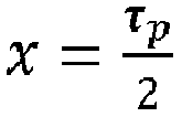
- Rotor nach einem der vorhergehenden Ansprüche, wobei sich das oder ein jeweiliges Paar lokaler Minimalwerte (16, 20) an einer Position in Umfangsrichtung befinden, an der ein magnetischer Streufluss ein lokales Maximum aufweist.
- Elektrische Maschine (28) für ein Fahrzeug (27), umfassend einen Stator (29) und einen innerhalb des Stators (29) drehbar gelagerten Rotor (1) nach einem der vorhergehenden Ansprüche.
- Fahrzeug (27), umfassend eine elektrische Maschine (28) nach Anspruch 10, welche dazu eingerichtet ist, das Fahrzeug (27) anzutreiben.
Applications Claiming Priority (1)
| Application Number | Priority Date | Filing Date | Title |
|---|---|---|---|
| DE102019117364.7A DE102019117364A1 (de) | 2019-06-27 | 2019-06-27 | Rotor für eine elektrische Maschine, elektrische Maschine für ein Fahrzeug und Fahrzeug |
Publications (2)
| Publication Number | Publication Date |
|---|---|
| EP3758194A1 true EP3758194A1 (de) | 2020-12-30 |
| EP3758194B1 EP3758194B1 (de) | 2025-09-17 |
Family
ID=71105243
Family Applications (1)
| Application Number | Title | Priority Date | Filing Date |
|---|---|---|---|
| EP20180288.1A Active EP3758194B1 (de) | 2019-06-27 | 2020-06-16 | Rotor für eine elektrische maschine, elektrische maschine für ein fahrzeug und fahrzeug |
Country Status (5)
| Country | Link |
|---|---|
| US (1) | US11601025B2 (de) |
| EP (1) | EP3758194B1 (de) |
| JP (1) | JP2021007290A (de) |
| CN (1) | CN112152351B (de) |
| DE (1) | DE102019117364A1 (de) |
Families Citing this family (2)
| Publication number | Priority date | Publication date | Assignee | Title |
|---|---|---|---|---|
| KR102823396B1 (ko) * | 2021-04-27 | 2025-06-20 | 한온시스템 주식회사 | 브러쉬리스 모터 |
| DE102022121410A1 (de) * | 2022-08-24 | 2024-02-29 | Seg Automotive Germany Gmbh | Rotor, elektrischen Maschine und Verfahren zum Betreiben einer elektrischen Maschine |
Citations (5)
| Publication number | Priority date | Publication date | Assignee | Title |
|---|---|---|---|---|
| JP2002209350A (ja) * | 2001-01-12 | 2002-07-26 | Meidensha Corp | 電動機又は発電機の回転子 |
| US20020175583A1 (en) * | 2001-05-25 | 2002-11-28 | Satoshi Kikuchi | Permanent magnet type rotating electrical machine and air conditioner using it |
| EP1610444A1 (de) * | 2004-06-24 | 2005-12-28 | Fanuc Ltd | Elektrischer Synchronmotor |
| US20070145850A1 (en) * | 2005-12-21 | 2007-06-28 | Hsu John S | Permanent magnet machine and method with reluctance poles and non-identical PM poles for high density operation |
| DE102012219175A1 (de) | 2011-11-02 | 2013-05-02 | Suzuki Motor Corp. | Drehende elektrische Maschine |
Family Cites Families (16)
| Publication number | Priority date | Publication date | Assignee | Title |
|---|---|---|---|---|
| JP2000316241A (ja) * | 1999-04-27 | 2000-11-14 | Toyota Motor Corp | 永久磁石埋め込み式モータ |
| JP3787756B2 (ja) * | 2000-08-29 | 2006-06-21 | 株式会社日立製作所 | 永久磁石式回転電機 |
| JP3768502B2 (ja) * | 2003-12-17 | 2006-04-19 | 財団法人工業技術研究院 | モータ内に永久磁石を設置したロータ機構 |
| JP4898201B2 (ja) * | 2005-12-01 | 2012-03-14 | アイチエレック株式会社 | 永久磁石回転機 |
| WO2008113082A1 (en) * | 2007-03-15 | 2008-09-18 | A.O. Smith Corporation | Interior permanent magnet motor including rotor with flux barriers |
| JP4900069B2 (ja) | 2007-06-13 | 2012-03-21 | トヨタ自動車株式会社 | 回転電機 |
| WO2012105656A1 (ja) * | 2011-02-04 | 2012-08-09 | 三菱電機株式会社 | 車両用永久磁石埋込型回転電機 |
| US20130169098A1 (en) * | 2011-12-28 | 2013-07-04 | Remy Technologies, Llc | Multi-grade magnet for an electric machine |
| JP5975759B2 (ja) * | 2012-06-29 | 2016-08-23 | 株式会社日立製作所 | 回転電機 |
| JP6190219B2 (ja) * | 2013-09-05 | 2017-08-30 | 株式会社小松製作所 | 電動機、ロータコア、および積層鋼板 |
| US10003227B2 (en) | 2015-03-20 | 2018-06-19 | GM Global Technology Operations LLC | Axially asymmetric configuration for interior permanent magnet machine |
| CN105337468B (zh) * | 2015-12-11 | 2017-12-19 | 北京新能源汽车股份有限公司 | 永磁同步电动机及具有其的电动汽车 |
| DE102016209709A1 (de) * | 2016-06-02 | 2017-12-21 | Volkswagen Aktiengesellschaft | Rotorkern |
| DE102016209711B4 (de) * | 2016-06-02 | 2025-07-10 | Volkswagen Aktiengesellschaft | Rotorkern |
| US10707707B2 (en) * | 2016-12-15 | 2020-07-07 | Ford Global Technologies, Llc | Electric machine rotor |
| CN108711977A (zh) * | 2018-06-25 | 2018-10-26 | 苏州汇川联合动力系统有限公司 | 转子及永磁电机 |
-
2019
- 2019-06-27 DE DE102019117364.7A patent/DE102019117364A1/de active Pending
-
2020
- 2020-06-05 CN CN202010504246.8A patent/CN112152351B/zh active Active
- 2020-06-16 EP EP20180288.1A patent/EP3758194B1/de active Active
- 2020-06-25 US US16/911,625 patent/US11601025B2/en active Active
- 2020-06-26 JP JP2020110381A patent/JP2021007290A/ja active Pending
Patent Citations (5)
| Publication number | Priority date | Publication date | Assignee | Title |
|---|---|---|---|---|
| JP2002209350A (ja) * | 2001-01-12 | 2002-07-26 | Meidensha Corp | 電動機又は発電機の回転子 |
| US20020175583A1 (en) * | 2001-05-25 | 2002-11-28 | Satoshi Kikuchi | Permanent magnet type rotating electrical machine and air conditioner using it |
| EP1610444A1 (de) * | 2004-06-24 | 2005-12-28 | Fanuc Ltd | Elektrischer Synchronmotor |
| US20070145850A1 (en) * | 2005-12-21 | 2007-06-28 | Hsu John S | Permanent magnet machine and method with reluctance poles and non-identical PM poles for high density operation |
| DE102012219175A1 (de) | 2011-11-02 | 2013-05-02 | Suzuki Motor Corp. | Drehende elektrische Maschine |
Also Published As
| Publication number | Publication date |
|---|---|
| CN112152351B (zh) | 2024-12-13 |
| JP2021007290A (ja) | 2021-01-21 |
| US11601025B2 (en) | 2023-03-07 |
| CN112152351A (zh) | 2020-12-29 |
| US20200412188A1 (en) | 2020-12-31 |
| EP3758194B1 (de) | 2025-09-17 |
| DE102019117364A1 (de) | 2020-12-31 |
Similar Documents
| Publication | Publication Date | Title |
|---|---|---|
| EP2195908B1 (de) | Elektrische maschine und rotoranordnung | |
| DE112015001725B4 (de) | Drehende elektrische Maschine mit eingebetteten Permanentmagneten | |
| EP2639936B1 (de) | Elektrische Maschine mit permanent erregtem Läufer und zugehöriger permanent erregter Läufer | |
| DE102011050094B4 (de) | Rotor für eine drehende elektrische Maschine | |
| DE112016004949T5 (de) | Permanentmagnetmotor | |
| DE112014000526T5 (de) | Rotor und drehende elektrische Maschine, die diesen Rotor enthält | |
| DE112012000667T5 (de) | Rotor für elektrische Maschine | |
| EP0729216A2 (de) | Hybriderregte Synchronmaschine | |
| DE112011101641T5 (de) | Rotor einer rotierenden elektrischen Maschine | |
| DE102012104052B4 (de) | Elektromotor mit Permanentmagneten in dessen Stator | |
| DE102021122768A1 (de) | Rotor einer elektrischen maschine | |
| DE112017005282T5 (de) | Rotor für rotierende elektrische Maschine | |
| DE112013006518T5 (de) | Elektrische Rotationsmaschine vom Permanentmagnet-Typ | |
| DE102017129640A1 (de) | Elektrischer maschinenrotor | |
| DE102021132373A1 (de) | Elektrische maschine | |
| DE112017000584T5 (de) | Rotor und Verfahren zur Auslegung des Rotors | |
| DE102012212775A1 (de) | Rotoranordnung für eine elektrische Maschine | |
| EP2942858B1 (de) | Rotorblechpaket | |
| DE102013205928A1 (de) | Rotor mit nachträglich einprägbarer permanenter Magnetisierung | |
| EP3758194B1 (de) | Rotor für eine elektrische maschine, elektrische maschine für ein fahrzeug und fahrzeug | |
| DE102017106052A1 (de) | Elektrische Rotationsmaschine vom Dauermagnettyp | |
| EP3618228A1 (de) | Statoranordnung für einen rotatorischen synchronmotor | |
| DE102017109256A1 (de) | Statoranordnung | |
| EP3616310B1 (de) | E-motor mit verdrehbaren rotorsegmenten zur reduzierung des magnetflusses | |
| DE112022001971T5 (de) | Rotor und Rotierende Elektrische Maschine |
Legal Events
| Date | Code | Title | Description |
|---|---|---|---|
| PUAI | Public reference made under article 153(3) epc to a published international application that has entered the european phase |
Free format text: ORIGINAL CODE: 0009012 |
|
| STAA | Information on the status of an ep patent application or granted ep patent |
Free format text: STATUS: THE APPLICATION HAS BEEN PUBLISHED |
|
| AK | Designated contracting states |
Kind code of ref document: A1 Designated state(s): AL AT BE BG CH CY CZ DE DK EE ES FI FR GB GR HR HU IE IS IT LI LT LU LV MC MK MT NL NO PL PT RO RS SE SI SK SM TR |
|
| AX | Request for extension of the european patent |
Extension state: BA ME |
|
| STAA | Information on the status of an ep patent application or granted ep patent |
Free format text: STATUS: REQUEST FOR EXAMINATION WAS MADE |
|
| 17P | Request for examination filed |
Effective date: 20210629 |
|
| RBV | Designated contracting states (corrected) |
Designated state(s): AL AT BE BG CH CY CZ DE DK EE ES FI FR GB GR HR HU IE IS IT LI LT LU LV MC MK MT NL NO PL PT RO RS SE SI SK SM TR |
|
| RAP3 | Party data changed (applicant data changed or rights of an application transferred) |
Owner name: VALEO EAUTOMOTIVE GERMANY GMBH |
|
| STAA | Information on the status of an ep patent application or granted ep patent |
Free format text: STATUS: EXAMINATION IS IN PROGRESS |
|
| 17Q | First examination report despatched |
Effective date: 20230209 |
|
| P01 | Opt-out of the competence of the unified patent court (upc) registered |
Effective date: 20230528 |
|
| REG | Reference to a national code |
Ref country code: DE Free format text: PREVIOUS MAIN CLASS: H02K0001270000 Ipc: H02K0001276000 Ref country code: DE Ref legal event code: R079 Ref document number: 502020011919 Country of ref document: DE Free format text: PREVIOUS MAIN CLASS: H02K0001270000 Ipc: H02K0001276000 |
|
| GRAP | Despatch of communication of intention to grant a patent |
Free format text: ORIGINAL CODE: EPIDOSNIGR1 |
|
| STAA | Information on the status of an ep patent application or granted ep patent |
Free format text: STATUS: GRANT OF PATENT IS INTENDED |
|
| RIC1 | Information provided on ipc code assigned before grant |
Ipc: H02K 29/03 20060101ALI20250326BHEP Ipc: H02K 1/276 20220101AFI20250326BHEP |
|
| INTG | Intention to grant announced |
Effective date: 20250416 |
|
| GRAS | Grant fee paid |
Free format text: ORIGINAL CODE: EPIDOSNIGR3 |
|
| GRAA | (expected) grant |
Free format text: ORIGINAL CODE: 0009210 |
|
| STAA | Information on the status of an ep patent application or granted ep patent |
Free format text: STATUS: THE PATENT HAS BEEN GRANTED |
|
| AK | Designated contracting states |
Kind code of ref document: B1 Designated state(s): AL AT BE BG CH CY CZ DE DK EE ES FI FR GB GR HR HU IE IS IT LI LT LU LV MC MK MT NL NO PL PT RO RS SE SI SK SM TR |
|
| REG | Reference to a national code |
Ref country code: GB Ref legal event code: FG4D Free format text: NOT ENGLISH |
|
| REG | Reference to a national code |
Ref country code: CH Ref legal event code: EP |
|
| REG | Reference to a national code |
Ref country code: IE Ref legal event code: FG4D Free format text: LANGUAGE OF EP DOCUMENT: GERMAN |
|
| REG | Reference to a national code |
Ref country code: DE Ref legal event code: R096 Ref document number: 502020011919 Country of ref document: DE |
|
| PG25 | Lapsed in a contracting state [announced via postgrant information from national office to epo] |
Ref country code: NO Free format text: LAPSE BECAUSE OF FAILURE TO SUBMIT A TRANSLATION OF THE DESCRIPTION OR TO PAY THE FEE WITHIN THE PRESCRIBED TIME-LIMIT Effective date: 20251217 |
|
| REG | Reference to a national code |
Ref country code: LT Ref legal event code: MG9D |
|
| PG25 | Lapsed in a contracting state [announced via postgrant information from national office to epo] |
Ref country code: FI Free format text: LAPSE BECAUSE OF FAILURE TO SUBMIT A TRANSLATION OF THE DESCRIPTION OR TO PAY THE FEE WITHIN THE PRESCRIBED TIME-LIMIT Effective date: 20250917 |
|
| PG25 | Lapsed in a contracting state [announced via postgrant information from national office to epo] |
Ref country code: HR Free format text: LAPSE BECAUSE OF FAILURE TO SUBMIT A TRANSLATION OF THE DESCRIPTION OR TO PAY THE FEE WITHIN THE PRESCRIBED TIME-LIMIT Effective date: 20250917 |
|
| PG25 | Lapsed in a contracting state [announced via postgrant information from national office to epo] |
Ref country code: GR Free format text: LAPSE BECAUSE OF FAILURE TO SUBMIT A TRANSLATION OF THE DESCRIPTION OR TO PAY THE FEE WITHIN THE PRESCRIBED TIME-LIMIT Effective date: 20251218 |
|
| PG25 | Lapsed in a contracting state [announced via postgrant information from national office to epo] |
Ref country code: SE Free format text: LAPSE BECAUSE OF FAILURE TO SUBMIT A TRANSLATION OF THE DESCRIPTION OR TO PAY THE FEE WITHIN THE PRESCRIBED TIME-LIMIT Effective date: 20250917 |
|
| REG | Reference to a national code |
Ref country code: NL Ref legal event code: MP Effective date: 20250917 |
|
| PG25 | Lapsed in a contracting state [announced via postgrant information from national office to epo] |
Ref country code: LV Free format text: LAPSE BECAUSE OF FAILURE TO SUBMIT A TRANSLATION OF THE DESCRIPTION OR TO PAY THE FEE WITHIN THE PRESCRIBED TIME-LIMIT Effective date: 20250917 |
|
| PG25 | Lapsed in a contracting state [announced via postgrant information from national office to epo] |
Ref country code: BG Free format text: LAPSE BECAUSE OF FAILURE TO SUBMIT A TRANSLATION OF THE DESCRIPTION OR TO PAY THE FEE WITHIN THE PRESCRIBED TIME-LIMIT Effective date: 20250917 |
|
| PG25 | Lapsed in a contracting state [announced via postgrant information from national office to epo] |
Ref country code: RS Free format text: LAPSE BECAUSE OF FAILURE TO SUBMIT A TRANSLATION OF THE DESCRIPTION OR TO PAY THE FEE WITHIN THE PRESCRIBED TIME-LIMIT Effective date: 20251217 |
|
| PG25 | Lapsed in a contracting state [announced via postgrant information from national office to epo] |
Ref country code: NL Free format text: LAPSE BECAUSE OF FAILURE TO SUBMIT A TRANSLATION OF THE DESCRIPTION OR TO PAY THE FEE WITHIN THE PRESCRIBED TIME-LIMIT Effective date: 20250917 |
|
| PG25 | Lapsed in a contracting state [announced via postgrant information from national office to epo] |
Ref country code: SM Free format text: LAPSE BECAUSE OF FAILURE TO SUBMIT A TRANSLATION OF THE DESCRIPTION OR TO PAY THE FEE WITHIN THE PRESCRIBED TIME-LIMIT Effective date: 20250917 |
|
| PG25 | Lapsed in a contracting state [announced via postgrant information from national office to epo] |
Ref country code: ES Free format text: LAPSE BECAUSE OF FAILURE TO SUBMIT A TRANSLATION OF THE DESCRIPTION OR TO PAY THE FEE WITHIN THE PRESCRIBED TIME-LIMIT Effective date: 20250917 |
|
| PG25 | Lapsed in a contracting state [announced via postgrant information from national office to epo] |
Ref country code: IT Free format text: LAPSE BECAUSE OF FAILURE TO SUBMIT A TRANSLATION OF THE DESCRIPTION OR TO PAY THE FEE WITHIN THE PRESCRIBED TIME-LIMIT Effective date: 20250917 |
|
| PG25 | Lapsed in a contracting state [announced via postgrant information from national office to epo] |
Ref country code: IS Free format text: LAPSE BECAUSE OF FAILURE TO SUBMIT A TRANSLATION OF THE DESCRIPTION OR TO PAY THE FEE WITHIN THE PRESCRIBED TIME-LIMIT Effective date: 20260117 |
|
| PG25 | Lapsed in a contracting state [announced via postgrant information from national office to epo] |
Ref country code: PT Free format text: LAPSE BECAUSE OF FAILURE TO SUBMIT A TRANSLATION OF THE DESCRIPTION OR TO PAY THE FEE WITHIN THE PRESCRIBED TIME-LIMIT Effective date: 20260119 Ref country code: CZ Free format text: LAPSE BECAUSE OF FAILURE TO SUBMIT A TRANSLATION OF THE DESCRIPTION OR TO PAY THE FEE WITHIN THE PRESCRIBED TIME-LIMIT Effective date: 20250917 |
|
| PG25 | Lapsed in a contracting state [announced via postgrant information from national office to epo] |
Ref country code: PL Free format text: LAPSE BECAUSE OF FAILURE TO SUBMIT A TRANSLATION OF THE DESCRIPTION OR TO PAY THE FEE WITHIN THE PRESCRIBED TIME-LIMIT Effective date: 20250917 |
|
| PG25 | Lapsed in a contracting state [announced via postgrant information from national office to epo] |
Ref country code: SK Free format text: LAPSE BECAUSE OF FAILURE TO SUBMIT A TRANSLATION OF THE DESCRIPTION OR TO PAY THE FEE WITHIN THE PRESCRIBED TIME-LIMIT Effective date: 20250917 Ref country code: EE Free format text: LAPSE BECAUSE OF FAILURE TO SUBMIT A TRANSLATION OF THE DESCRIPTION OR TO PAY THE FEE WITHIN THE PRESCRIBED TIME-LIMIT Effective date: 20250917 |