EP3758145A1 - Antenna structure - Google Patents
Antenna structure Download PDFInfo
- Publication number
- EP3758145A1 EP3758145A1 EP18906886.9A EP18906886A EP3758145A1 EP 3758145 A1 EP3758145 A1 EP 3758145A1 EP 18906886 A EP18906886 A EP 18906886A EP 3758145 A1 EP3758145 A1 EP 3758145A1
- Authority
- EP
- European Patent Office
- Prior art keywords
- antenna
- antenna structure
- antenna elements
- base
- structure according
- Prior art date
- Legal status (The legal status is an assumption and is not a legal conclusion. Google has not performed a legal analysis and makes no representation as to the accuracy of the status listed.)
- Withdrawn
Links
- 230000005855 radiation Effects 0.000 claims description 52
- 239000000463 material Substances 0.000 claims description 41
- 239000006260 foam Substances 0.000 claims description 11
- 239000000853 adhesive Substances 0.000 claims description 8
- 230000001070 adhesive effect Effects 0.000 claims description 8
- 238000005388 cross polarization Methods 0.000 claims description 8
- 230000001902 propagating effect Effects 0.000 claims description 2
- 230000003071 parasitic effect Effects 0.000 description 24
- 230000010287 polarization Effects 0.000 description 17
- 239000000758 substrate Substances 0.000 description 13
- 238000003491 array Methods 0.000 description 8
- 238000010586 diagram Methods 0.000 description 8
- 239000004020 conductor Substances 0.000 description 6
- 238000009434 installation Methods 0.000 description 6
- 239000004593 Epoxy Substances 0.000 description 4
- JOYRKODLDBILNP-UHFFFAOYSA-N Ethyl urethane Chemical compound CCOC(N)=O JOYRKODLDBILNP-UHFFFAOYSA-N 0.000 description 4
- 238000005452 bending Methods 0.000 description 4
- 239000000470 constituent Substances 0.000 description 4
- 229920005989 resin Polymers 0.000 description 4
- 239000011347 resin Substances 0.000 description 4
- 239000007767 bonding agent Substances 0.000 description 3
- -1 for example Substances 0.000 description 3
- 239000000203 mixture Substances 0.000 description 3
- 229920001296 polysiloxane Polymers 0.000 description 3
- NIXOWILDQLNWCW-UHFFFAOYSA-N acrylic acid group Chemical group C(C=C)(=O)O NIXOWILDQLNWCW-UHFFFAOYSA-N 0.000 description 2
- 230000005540 biological transmission Effects 0.000 description 2
- 238000010276 construction Methods 0.000 description 2
- 230000009977 dual effect Effects 0.000 description 2
- 230000000694 effects Effects 0.000 description 2
- 239000011888 foil Substances 0.000 description 2
- 238000010438 heat treatment Methods 0.000 description 2
- 238000002372 labelling Methods 0.000 description 2
- 230000010363 phase shift Effects 0.000 description 2
- 239000000565 sealant Substances 0.000 description 2
- 229920003002 synthetic resin Polymers 0.000 description 2
- 239000000057 synthetic resin Substances 0.000 description 2
- RYGMFSIKBFXOCR-UHFFFAOYSA-N Copper Chemical compound [Cu] RYGMFSIKBFXOCR-UHFFFAOYSA-N 0.000 description 1
- 241001465754 Metazoa Species 0.000 description 1
- 239000005062 Polybutadiene Substances 0.000 description 1
- 239000004698 Polyethylene Substances 0.000 description 1
- 239000004642 Polyimide Substances 0.000 description 1
- BQCADISMDOOEFD-UHFFFAOYSA-N Silver Chemical compound [Ag] BQCADISMDOOEFD-UHFFFAOYSA-N 0.000 description 1
- 230000004308 accommodation Effects 0.000 description 1
- 150000001336 alkenes Chemical class 0.000 description 1
- 238000013459 approach Methods 0.000 description 1
- 239000012298 atmosphere Substances 0.000 description 1
- 239000011248 coating agent Substances 0.000 description 1
- 238000000576 coating method Methods 0.000 description 1
- 238000004891 communication Methods 0.000 description 1
- 229920001577 copolymer Polymers 0.000 description 1
- 229910052802 copper Inorganic materials 0.000 description 1
- 239000010949 copper Substances 0.000 description 1
- 230000002542 deteriorative effect Effects 0.000 description 1
- 229920001971 elastomer Polymers 0.000 description 1
- 230000005684 electric field Effects 0.000 description 1
- 230000007613 environmental effect Effects 0.000 description 1
- 230000008020 evaporation Effects 0.000 description 1
- 238000001704 evaporation Methods 0.000 description 1
- 239000011521 glass Substances 0.000 description 1
- 230000005484 gravity Effects 0.000 description 1
- 239000011810 insulating material Substances 0.000 description 1
- 238000000034 method Methods 0.000 description 1
- 238000012986 modification Methods 0.000 description 1
- 230000004048 modification Effects 0.000 description 1
- 238000000465 moulding Methods 0.000 description 1
- JRZJOMJEPLMPRA-UHFFFAOYSA-N olefin Natural products CCCCCCCC=C JRZJOMJEPLMPRA-UHFFFAOYSA-N 0.000 description 1
- 230000010355 oscillation Effects 0.000 description 1
- 229920002857 polybutadiene Polymers 0.000 description 1
- 229920000573 polyethylene Polymers 0.000 description 1
- 229920001721 polyimide Polymers 0.000 description 1
- 239000004810 polytetrafluoroethylene Substances 0.000 description 1
- 229920001343 polytetrafluoroethylene Polymers 0.000 description 1
- 229920000915 polyvinyl chloride Polymers 0.000 description 1
- 239000004800 polyvinyl chloride Substances 0.000 description 1
- 238000002360 preparation method Methods 0.000 description 1
- 238000012545 processing Methods 0.000 description 1
- 239000005060 rubber Substances 0.000 description 1
- 230000008054 signal transmission Effects 0.000 description 1
- 229910052709 silver Inorganic materials 0.000 description 1
- 239000004332 silver Substances 0.000 description 1
- 239000002904 solvent Substances 0.000 description 1
- 238000012546 transfer Methods 0.000 description 1
- 238000004078 waterproofing Methods 0.000 description 1
- 239000002023 wood Substances 0.000 description 1
Images



Classifications
-
- H—ELECTRICITY
- H01—ELECTRIC ELEMENTS
- H01Q—ANTENNAS, i.e. RADIO AERIALS
- H01Q21/00—Antenna arrays or systems
- H01Q21/06—Arrays of individually energised antenna units similarly polarised and spaced apart
- H01Q21/061—Two dimensional planar arrays
- H01Q21/065—Patch antenna array
-
- H—ELECTRICITY
- H01—ELECTRIC ELEMENTS
- H01Q—ANTENNAS, i.e. RADIO AERIALS
- H01Q1/00—Details of, or arrangements associated with, antennas
- H01Q1/44—Details of, or arrangements associated with, antennas using equipment having another main function to serve additionally as an antenna, e.g. means for giving an antenna an aesthetic aspect
-
- H—ELECTRICITY
- H01—ELECTRIC ELEMENTS
- H01Q—ANTENNAS, i.e. RADIO AERIALS
- H01Q1/00—Details of, or arrangements associated with, antennas
- H01Q1/12—Supports; Mounting means
- H01Q1/22—Supports; Mounting means by structural association with other equipment or articles
- H01Q1/24—Supports; Mounting means by structural association with other equipment or articles with receiving set
- H01Q1/241—Supports; Mounting means by structural association with other equipment or articles with receiving set used in mobile communications, e.g. GSM
- H01Q1/246—Supports; Mounting means by structural association with other equipment or articles with receiving set used in mobile communications, e.g. GSM specially adapted for base stations
-
- H—ELECTRICITY
- H01—ELECTRIC ELEMENTS
- H01Q—ANTENNAS, i.e. RADIO AERIALS
- H01Q1/00—Details of, or arrangements associated with, antennas
- H01Q1/40—Radiating elements coated with or embedded in protective material
-
- H—ELECTRICITY
- H01—ELECTRIC ELEMENTS
- H01Q—ANTENNAS, i.e. RADIO AERIALS
- H01Q21/00—Antenna arrays or systems
- H01Q21/06—Arrays of individually energised antenna units similarly polarised and spaced apart
- H01Q21/08—Arrays of individually energised antenna units similarly polarised and spaced apart the units being spaced along or adjacent to a rectilinear path
-
- H—ELECTRICITY
- H01—ELECTRIC ELEMENTS
- H01Q—ANTENNAS, i.e. RADIO AERIALS
- H01Q21/00—Antenna arrays or systems
- H01Q21/24—Combinations of antenna units polarised in different directions for transmitting or receiving circularly and elliptically polarised waves or waves linearly polarised in any direction
-
- H—ELECTRICITY
- H01—ELECTRIC ELEMENTS
- H01Q—ANTENNAS, i.e. RADIO AERIALS
- H01Q25/00—Antennas or antenna systems providing at least two radiating patterns
- H01Q25/001—Crossed polarisation dual antennas
-
- H—ELECTRICITY
- H01—ELECTRIC ELEMENTS
- H01Q—ANTENNAS, i.e. RADIO AERIALS
- H01Q3/00—Arrangements for changing or varying the orientation or the shape of the directional pattern of the waves radiated from an antenna or antenna system
- H01Q3/26—Arrangements for changing or varying the orientation or the shape of the directional pattern of the waves radiated from an antenna or antenna system varying the relative phase or relative amplitude of energisation between two or more active radiating elements; varying the distribution of energy across a radiating aperture
- H01Q3/30—Arrangements for changing or varying the orientation or the shape of the directional pattern of the waves radiated from an antenna or antenna system varying the relative phase or relative amplitude of energisation between two or more active radiating elements; varying the distribution of energy across a radiating aperture varying the relative phase between the radiating elements of an array
- H01Q3/34—Arrangements for changing or varying the orientation or the shape of the directional pattern of the waves radiated from an antenna or antenna system varying the relative phase or relative amplitude of energisation between two or more active radiating elements; varying the distribution of energy across a radiating aperture varying the relative phase between the radiating elements of an array by electrical means
- H01Q3/36—Arrangements for changing or varying the orientation or the shape of the directional pattern of the waves radiated from an antenna or antenna system varying the relative phase or relative amplitude of energisation between two or more active radiating elements; varying the distribution of energy across a radiating aperture varying the relative phase between the radiating elements of an array by electrical means with variable phase-shifters
-
- H—ELECTRICITY
- H04—ELECTRIC COMMUNICATION TECHNIQUE
- H04W—WIRELESS COMMUNICATION NETWORKS
- H04W88/00—Devices specially adapted for wireless communication networks, e.g. terminals, base stations or access point devices
- H04W88/08—Access point devices
- H04W88/085—Access point devices with remote components
-
- H—ELECTRICITY
- H01—ELECTRIC ELEMENTS
- H01Q—ANTENNAS, i.e. RADIO AERIALS
- H01Q9/00—Electrically-short antennas having dimensions not more than twice the operating wavelength and consisting of conductive active radiating elements
- H01Q9/04—Resonant antennas
- H01Q9/0407—Substantially flat resonant element parallel to ground plane, e.g. patch antenna
- H01Q9/0414—Substantially flat resonant element parallel to ground plane, e.g. patch antenna in a stacked or folded configuration
Definitions
- the present invention relates to an antenna structure.
- Patent Document 1 describes a method of waterproofing and supporting an antenna element in which an antenna element in a flat-plate shape is set in a cavity of a mold, and a synthetic resin material in a fluidized state is injected into a gap formed between the flat-plate-shaped antenna element and an inner wall of the cavity and solidified, to thereby seal and contain the flat-plate-shaped antenna element in a synthetic resin package.
- Patent Document 2 describes an antenna that is low profile and capable of resisting environmental and physical impact.
- the antenna can be mounted on vehicles, aircraft, spacecraft, manhole covers, utility covers, equipment cabinets, personnel, and animals.
- Patent Document 3 describes a wireless communication module including a flexible laminate base plate configured from multiple laminated flexible base materials and having a cavity, a wireless IC chip disposed in the cavity, and a sealant which fills the cavity so as to cover the wireless IC chip.
- the sealant is a material more rigid than the flexible base material.
- Loop-form electrodes configured from coil patterns are built into the flexible laminate base plate, and the loop-form electrodes are electrically connected to the wireless IC chip.
- An object of the present invention is to provide an antenna structure that can be attached with ease and is likely to blend into environments.
- the invention described in claim 1 provides an antenna structure including: plural antenna elements configured individually and arranged discretely; and a base adhering to at least side surfaces of the plural antenna elements, being embedded with the plural antenna elements to fix thereof, and forming an outer shape of the antenna structure into a plate shape.
- the invention described in claim 2 is the antenna structure described in claim 1, further including a distributor configured separately from the plural antenna elements, the distributor distributing a signal to the plural antenna elements, combining a signal from the plural antenna elements or changing a phase of a signal, and being embedded in the base to be fixed with at least a side surface of the distributor adhering to the base.
- the invention described in claim 3 is the antenna structure described in claim 2, wherein the plural antenna elements and the distributor are connected by a coaxial cable being embedded in the base and having flexibility.
- the invention described in claim 4 is the antenna structure described in claim 2 or 3, wherein the base is constituted by a material having flexibility, and the antenna elements and the distributor are constituted by a material not having flexibility.
- the invention described in claim 5 is the antenna structure described in claim 4, wherein the material constituting the base has a hardness not more than a Shore D hardness of 60.
- the invention described in claim 6 is the antenna structure described in any one of claims 1 to 5, wherein the plural antenna elements are arranged in a line.
- the invention described in claim 7 is the antenna structure described in any one of claims 1 to 6, wherein the base has a circular or polygonal planar shape.
- the invention described in claim 8 is the antenna structure described in claim 7, wherein the base is rotated around a center of the planar shape of the base as an axis, to thereby make a direction of a tilt constituted by the plural antenna elements correspond to a bearing angle of radio frequencies.
- each of the plural antenna elements includes a radiation element part radiating or receiving radio frequencies, the radiation element part being separated from the base inside the antenna element.
- each of the plural antenna elements includes a gap or a foam constituting an air layer on the radiation element part.
- the invention described in claim 11 is the antenna structure described in claim 2, wherein the distributor includes a distribution circuit propagating a signal, the distribution circuit being separated from the base inside the distributor.
- the invention described in claim 12 is the antenna structure described in claim 11, wherein the distributor includes a gap or a foam constituting an air layer on the distribution circuit.
- each of the plural antenna elements includes a radiation element part transmitting or receiving radio frequencies, the radiation element part being a patch antenna provided with a radiation electrode and a ground electrode facing each other, and the radiation electrode has a circular planar shape and is provided with two feeding electrodes to make it possible to transmit or receive radio frequencies of cross polarizations.
- the invention described in claim 14 is the antenna structure described in claim 13, wherein the plural antenna elements are arranged in a line to constitute a sector antenna, and distributors each distributing a signal to the plural antenna elements, combining a signal from the plural antenna elements or changing a phase of a signal are provided to correspond to the respective cross polarizations, the distributors being divided to be provided on both sides of an array arranging the plural antenna elements.
- the invention described in claim 15 is the antenna structure described in claim 14, further including input-output signal lines corresponding to the respective cross polarizations, the input-output signal lines inputting signals from outside and outputting signals to outside, wherein the input-output signal lines are drawn out of the base in a direction along the array of the plural antenna elements.
- the invention described in claim 16 is the antenna structure described in any one of claims 1 to 15, wherein a sheet on which a picture is drawn is attached on one of a front surface and a back surface of the antenna structure, and an adhesive is applied on the other one of the front surface and the back surface of the antenna structure.
- the antenna structure it is possible to make the antenna structure have the flexibility as a whole, as compared to the case in which the base is not constituted by the material having flexibility.
- the antenna elements can function as a sector antenna, as compared to the case in which the antenna elements are not arranged in a line.
- the characteristics of the antenna element or the characteristics of the distribution circuit as a single item can be maintained, as compared to the case in which the gap or foam is not provided.
- the distributors can be arranged with ease, as compared to the case in which the distributors are not arranged on the both sides of the array.
- the input-output signal lines can be arranged with ease, as compared to the case in which the input-output signal lines are not arranged in the direction along the array of the antenna elements.
- the antenna structure can be easily installed and is likely to blend into environments.
- the radio frequencies handled by a base station antenna are increasing to five, six, and so forth. For this reason, accommodation of plural antenna elements provided in accordance with the number of radio frequencies in a single radome approaches the limit.
- the radio frequencies to be added in the future have high frequencies. The higher the frequency, the more the straightness and the shorter the range.
- an antenna has been formed into low profile corresponding to high frequency and has been provided with flexibility in some situations, to thereby make it possible to install the antenna with ease by attaching thereof to a wall, ceiling, floor or the like in a room, a wall surface of a building, a pillar provided on a road, a road surface or the like, and to thereby consider an antenna structure that is sensitive to landscapes or environments.
- FIG. 1 is a perspective view of an example of an antenna structure 1 to which the first exemplary embodiment is applied.
- a base 60 to be described later is transparent, and thereby the interior of the antenna structure 1 can be observed.
- the antenna structure 1 is configured to have a plate-like outer shape.
- the antenna structure 1 includes: plural (in FIG. 1 , six) antenna elements 10 transmitting or receiving the radio frequencies; distributors 20 and 30 distributing signals to the antenna elements 10 or combining signals from the antenna elements 10; and input-output signal lines 40-1 and 40-2 transmitting signals to the antenna structure 1 or receiving signals from the antenna structure 1.
- transmitting and receiving signals are collectively referred to as signal transmission/reception.
- the antenna structure 1 functions as a sector antenna in which the antenna elements 10 are arranged in a line.
- the antenna structure 1 is of a dual polarization type in which one group of polarizations is transmitted or received on the side A and the other group of polarizations is transmitted and received on the side B. Accordingly, two input-output signal lines 40 are provided: A-side signals are transmitted and received by the input-output signal line 40-1, and B-side signals are transmitted and received by the input-output signal line 40-2. In the case where the input-output signal lines 40-1 and 40-2 are not distinguished, they are referred to as the input-output signal lines 40.
- the direction in which the antenna elements 10 are arranged in a line is assumed to be the z direction
- the direction along the plate-like surface of the antenna structure 1 and orthogonal to the direction in which the antenna elements 10 are arranged in a line is assumed to be the x direction.
- the direction orthogonal to the x direction and z direction in the right-hand screw relationship is assumed to be the y direction.
- the surface of the antenna structure 1 viewed from the +y direction is referred to as the front surface of the antenna structure 1
- the surface of the antenna structure 1 viewed from the -y direction is referred to as the back surface of the antenna structure 1.
- the surface viewed from the direction orthogonal to the y direction is referred to as the side surface.
- the back surface side of the antenna structure 1 is referred to as the lower side
- the front surface side of the antenna structure 1 is referred to as the upper side. The same is true in the antenna elements 10 and the distributors 20 and 30.
- the distributor 30 is provided on the antenna elements 10 side and the distributor 20 is provided on the input-output signal line 40 side.
- the input-output signal line 40 is constituted by a coaxial cable 41 and a connector 42, in which one end portion of the coaxial cable 41 is connected to the distributor 20 and the other end portion thereof is connected to the connector 42.
- the antenna structure 1 is connected to a not-shown signal input/output device via the connector 42.
- the antenna structure 1 includes plural signal lines 50 connecting between the antenna elements 10 and the distributors 30 and between the distributors 20 and the distributors 30.
- the signal line 50 is a coaxial cable having flexibility, as an example.
- the antenna structure 1 includes a base 60 embedding and accommodating the antenna elements 10, the distributors 20 and 30, and the signal lines 50. Note that a part of the coaxial cable 41 and the connector 42 of the input-output signal line 40 are protruded to the outside from the base 60.
- Each of the antenna elements 10, the distributors 20 and 30 is configured as an individual (separate) component (module) without flexibility (with rigidity).
- the antenna elements 10 are discretely arranged. The structures of the antenna elements 10, the distributors 20 and 30 will be described later.
- the base 60 is constituted by resin, for example, epoxy, urethane, or polyimide. Consequently, the base 60 is embedded with the antenna elements 10, the distributors 20 and 30, the input-output signal lines 40 and the signal lines 50 to fix the relative positions of the antenna elements 10, the distributors 20 and 30 and the like, as well as forms (molds) the outer shape of the antenna structure 1 into a plate shape. In other words, the antenna structure 1 is in the state of being solidified by the base 60.
- the base 60 will be described later.
- the base 60 is embedded with asperities formed by the antenna elements 10, the distributors 20 and 30 and so forth, to thereby make the back surface and the front surface of the antenna structure 1 flat. Consequently, the antenna structure 1 is in the plate shape. Note that to be flat refers to the asperities formed by the antenna elements 10, the distributors 20, 30 and so forth in a degree not being sensed. Note that the back surface and the front surface of the antenna structure 1 are in parallel with each other here.
- the antenna structure 1 has a rectangular plate-like planar shape, and the side surface thereof is tapered.
- the front surface is small as compared to the back surface.
- the side surface may be perpendicular to the front surface and the back surface; to the contrary, the side surface may be conversely tapered to make the back surface small as compared to the front surface.
- the reason why the side surface is tapered is to obscure the thickness of the antenna structure 1 (a magnitude in the y direction).
- the thickness of the antenna structure 1 varies in accordance with the frequencies to be used. Accordingly, in the case where the antenna structure 1 is thin, it is not required to taper the side surface.
- composition of the base 60 by a material having the flexibility allows the antenna structure 1 to have the flexibility as a whole.
- use of the coaxial cable having the flexibility as the signal line 50 causes the antenna structure 1 to have the flexibility as a whole even though the antenna elements 10, the distributors 20 and 30 are constituted by components that do not have the flexibility (that have the rigidity).
- the distributors 20 and 30 are constituted by components that do not have the flexibility (that have the rigidity).
- the distributors 20 and 30 are constituted by constituting each of the antenna elements 10, the distributors 20 and 30 to occupy a small area in the antenna structure 1, the flexibility of the antenna structure 1 is increased.
- the two-branch distributor 20 and the three-branch distributor 30 are adopted to distribute the signals to the six antenna elements 10; however, a six-branch distributor may be used.
- the area occupied by each of the distributors 20 and 30 is smaller than the area occupied by the six-branch distributor, it is preferable to adopt the distributors 20 and 30 separated into the two stages.
- the distributors 20 and 30 in the direction orthogonal to the bending direction in the antenna structure 1 to secure a bendable region, the antenna structure 1 is more likely to be bent.
- the antenna structure 1 With such an antenna structure 1, coating of an adhesive in advance to one of the front surface and the back surface by a double-faced tape or the like makes it possible to install the antenna structure 1 with ease by attaching thereof to a wall, a ceiling, a floor or the like in doors. At this time, the antenna structure 1 provided with flexibility is likely to be attached to a wall or a pillar having a curved surface. Attaching a sheet on which a pattern like the wall, ceiling or floor is drawn to a surface of the antenna structure 1 not coated with the adhesive enables the antenna structure 1 to blend into environments with ease. Moreover, if the wall, ceiling, or floor is constructed after the antenna structure 1 is embedded in the wall, ceiling or floor, the antenna structure 1 is difficult to be seen (visually observed).
- the film on which the state before attaching the antenna structure 1 is printed may be pasted on a surface of the antenna structure 1. With this, the state before the antenna structure 1 is attached can be reproduced.
- patterns may be drawn on a surface of the antenna structure 1 not coated with the adhesive.
- labeling of a name such as "Meeting Room A” or "evacuation area”
- guidance display such as "evacuation route ->”
- pictures In addition to the patterns of the wall, ceiling, floor or the like, drawings such as labeling of names, guidance displays or the like provided on the surface of the antenna structure 1 not coated with the adhesive are referred to as pictures. Note that, in the case where a picture is provided on a film, it is preferable that the film rarely affects characteristics of the antenna.
- the antenna structure 1 blends into the environments and does not damage the landscapes and atmosphere.
- the antenna structure 1 may be embedded in a surface portion of a road.
- the antenna structure 1 provided with flexibility makes it possible to attach the antenna structure 1 onto the road surface to follow the irregularities thereon. In this case, strength not to be broken by a vehicle or the like that runs on or goes through is required of the antenna structure 1. Even in this case, since the antenna structure 1 is solidified by the base 60, the strength is likely to be kept according to selection of a material constituting the base 60.
- the antenna elements 10, the distributors 20 and 30 are constituted as the components that do not have the flexibility (that have the rigidity), whereas the input-output signal lines 40 and the signal lines 50 are constituted by the coaxial cables having the flexibility. Consequently, even though the base 60 is constituted by a material having the flexibility to cause the antenna structure 1 to have the flexibility as a whole, variations in the characteristics as the antenna can be suppressed.
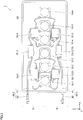
- FIG. 2 is a plan view of the antenna structure 1.
- the antenna structure 1 includes the six antenna elements 10.
- the individual antenna elements 10 are referred to as the antenna elements 10-1, 10-2, 10-3, 10-4, 10-5 and 10-6. Note that the x direction, the y direction, and the z direction are the same as FIG. 1 .
- the antenna element 10 has a planar shape of a square in which the corners are rounded off. Note that the corners do not have to be rounded off, and the planar shape does not have to be a square.
- the antenna structure 1 includes a pair of two-branch distributors 20.
- the individual distributors 20 are referred to as the distributors 20-1 and 20-2.
- the antenna structure 1 includes four three-branch distributors 30.
- the individual distributors 30 are referred to as the distributors 30-1, 30-2, 30-3 and 30-4.
- Two signals are inputted to the antenna structure 1 from the two input-output signal lines 40 (the input-output signal lines 40-1 and 40-2).
- Signals of polarizations 90-degree different in oscillating direction (specifically, polarizations of ⁇ 45° with respect to the z direction) are transmitted to the input-output signal lines 40-1 and 40-2.
- the antenna structure 1 is of a dual polarization type and is capable of dealing with 2MIMO (Multiple-Input and Multiple-Output).
- the input-output signal line 40-1 is connected to an input terminal of the two-branch distributor 20-1.
- the distributor 20-1 branches the inputted signal into two to output thereof from two output terminals.
- One of the output terminals of the distributor 20-1 is connected to an input terminal of the distributor 30-1.
- the other output terminal of the distributor 20-1 is connected to an input terminal of the distributor 30-2.
- the input-output signal line 40-2 is connected to an input terminal of the two-branch distributor 20-2.
- the distributor 20-2 branches the inputted signal into two to output thereof from two output terminals.
- One of the output terminals of the distributor 20-2 is connected to an input terminal of the distributor 30-3.
- the other output terminal of the distributor 20-2 is connected to an input terminal of the distributor 30-4.
- Each of the antenna elements 10-1 to 10-6 includes two input terminals.
- Each of three output terminals of the three-branch distributor 30-1 is connected to one of the input terminals of each of the antenna elements 10-1, 10-2 and 10-3. Moreover, each of three output terminals of the distributor 30-2 is connected to one of the input terminals of each of the antenna elements 10-4, 10-5 and 10-6.
- Each of three output terminals of the three-branch distributor 30-3 is connected to the other one of the input terminals of each of the antenna elements 10-1, 10-2 and 10-3. Moreover, each of three output terminals of the distributor 30-4 is connected to the other one of the input terminals of each of the antenna elements 10-4, 10-5 and 10-6.
- the signal inputted to the input-output signal line 40-1 is distributed to one of the terminals of each of the antenna elements 10-1 to 10-6 (side A) via the distributors 20-1, 30-1 and 30-2.
- the signal inputted to the input-output signal line 40-2 is distributed to the other one of the terminals of each of the antenna elements 10-1 to 10-6 via the distributors 20-2, 30-3 and 30-4.
- the signals received by the antenna elements 10-1 to 10-6 are combined by reversely going through the above route to be outputted from the input-output signal lines 40-1 and 40-2.
- the distributors 20 and 30 and the signal lines 50 corresponding to the two respective polarizations are divided to be disposed on the side A and the side B (both sides) of an array of the antenna elements 10-1 to 10-6. This allows the distributors 20, 30 and the signal lines 50 to be arranged with ease.
- the input-output signal lines 40 (the input-output signal lines 40-1 and 40-2) corresponding to the two polarizations are provided in the direction along an array of the antenna elements 10-1 to 10-6, and are projected from a short side of the base 60 having a square planar shape.
- the antenna structure 1 to use the antenna structure 1 as a sector antenna, in the case where the array of the antenna elements 10-1 to 10-6 (the z direction) is arranged in a direction perpendicular to the ground surface (the vertical direction), which is the direction of gravity, wiring to be connected to the input-output signal lines 40 from above (in doors, from the ceiling side) or below (in doors, from the floor side) may be provided. In other words, wiring construction can be easily carried out.
- the input-output signal lines 40 of the adjacent antenna structure 1 do not interrupt.
- the wiring from the antenna structure 1 arranged on the upper side may be provided above, and the wiring from the antenna structure 1 arranged on the lower side may be provided below.
- FIGS. 3A and 3B show diagrams illustrating a structure of the antenna element 10.
- FIG. 3A is a cross-sectional view of vicinity of the antenna element 10 (a cross-sectional view in the x direction in FIG. 2 )
- FIG. 3B is a plan view of a radiation element part 11 of the antenna element 10.
- FIG. 3A shows, in addition to the antenna element 10, the base 60 in the vicinity of the antenna element 10.
- the base 60 includes: a lower layer part 61 positioned at the lower side of the antenna structure 1; an embedding part 62 embedding the antenna elements 10, the distributors 20 and 30, the signal lines 50 and part of the input-output signal lines 40; and an upper layer part 63 positioned at the upper side of the antenna structure 1.
- the lower layer part 61, the embedding part 62 and the upper layer part 63 are configured as one piece (a continuous structure). That is, the antenna elements 10, the distributors 20 and 30, the signal lines 50 and part of the input-output signal lines 40 are sealed to be enclosed by the lower layer part 61, the embedding part 62 and the upper layer part 63 constituting the base 60.
- the antenna structure 1 is in the state of being solidified by the base 60. Then, the antenna structure 1 is configured in a flat-plate shape having a flat surface.
- the lower layer part 61, the embedding part 62 and the upper layer part 63 do not have to be configured as one piece (a continuous structure).
- the antenna element 10 includes: a radiation element part 11 constituting a patch antenna; a parasitic element part 12; and a container part 13.
- the radiation element part 11 includes an insulating substrate 111; a ground electrode 112 provided on a back surface (a surface in the -y direction) of the insulating substrate 111; and a radiation electrode 113 provided on a front surface (a surface in the +y direction) of the insulating substrate 111.
- the parasitic element part 12 includes an insulating substrate 121 and a parasitic electrode 122 provided on a front surface (a surface in the +y direction) of the insulating substrate 121.
- the insulating substrates 111 and 121 are constituted by an electrical insulating material with a low dielectric loss (tan ⁇ ), for example, glass epoxy, polytetrafluoroethylene, or the like.
- the ground electrode 112, the radiation electrode 113 and the parasitic electrode 122 are constituted by a thin conductive material, such as copper (foil) or silver (foil).
- the container part 13 includes: a bottom part 131 having a square outer shape in a planar view with a circular cup-shaped hollow at the center in a planar view; and a lid part 132 holding the parasitic element part 12 and functioning as a lid for the bottom part 131.
- the bottom part 131 contains the radiation element part 11.
- the parasitic element part 12 is fitted into the lid part 132 from the front surface side (from the y direction side). In other words, the parasitic element part 12 is dropped into a concave provided on the front surface side (the y direction side) of the lid part 132 so that the front surface of the lid part 132 and the front surface of the parasitic element part 12 are flat.
- the container part 13 holds the radiation element part 11 and holds the parasitic element part 12 at a predetermined distance from the radiation element part 11. That is to say, the radiation element part 11 and the parasitic element part 12 are disposed to face each other.
- the bottom part 131 and the lid part 132 are fastened.
- holes provided in the lid part 132 are fitted over the protrusions provided on the bottom part 131 to thereby perform positioning between the bottom part 131 and the lid part 132 (refer to small circles depicted on the front surface of the antenna element 10 in FIGS. 1 , 2A and 2B ).
- the bottom part 131 and the lid part 132 are fixed by a bonding agent.
- the antenna elements 10 are enclosed by the base 60 (the lower layer part 61, the embedding part 62 and the upper layer part 62) to be sealed; thereby the bottom part 131 and the lid part 132 may be simply fixed by the bonding agent.
- the bottom part 131 and the lid part 132 may be fastened by screws, or may be fastened by a snap-fit structure in which convex members are fitted into concave parts.
- the insulating substrate 111 of the radiation element part 11 is configured to have a circular planar shape. Then, the ground electrode 112 is formed on all over the back surface (the surface in the -y direction) of the insulating substrate 111. At the center portion of the front surface (the surface in the +y direction) of the insulating substrate 111, the radiation electrode 113 having a circular planar shape is formed. In other words, the radiation element part 11 constitutes the patch antenna.
- feeding electrodes 114-1 and 114-2 are provided to enable inner conductors (core wires) of the signal lines 50 constituted by the coaxial cables to be connected.
- the inner conductor (the core wire) of the signal line 50 constituted by the coaxial cable is connected.
- the feeding electrodes 114-1 and 114-2 of the radiation electrode 113 are provided to be separated 90° around the center of the radiation electrode 113.
- feeding the radiation electrode 113 from the feeding electrodes 114-1 and 114-2 separated 90° from each other makes it possible to radiate polarizations having oscillation directions of the electric field different 90° from each other (cross polarizations). In other words, it is possible to transmit/receive the radio frequencies of orthogonal polarizations by the single radiation electrode 113.
- an outer conductor (a shield) of the signal line 50 constituted by the coaxial cable is connected to the ground electrode 112 provided on the back surface of the insulating substrate 111 by a piece of hardware 115.
- the piece of hardware 115 is provided to cover the exposed inner conductor (the core wire).
- the feeding electrodes 114-1 and 114-2 are provided +45° and - 45° to the z direction, respectively; therefore, the polarizations are ⁇ 45° polarizations to the vertical direction. Note that, when the feeding electrodes 114-1 and 114-2 are provided 0° and 90° to the z direction, respectively, the polarizations are the polarization in the vertical direction (the vertical polarization) and the polarization orthogonal to the vertical direction (the horizontal polarization).
- the container part 13 holds the radiation element part 11 and the parasitic element part 12 and seals (encapsulates) the radiation element part 11 and the parasitic element part 12 for preventing the material constituting the base 60 from entering.
- the radiation element part 11 and the parasitic element part 12 of the antenna element 10 are separated from the base 60 in the interior of the antenna element 10.
- the antenna element 10 maintains the characteristics as they were designed for a single item.
- the upper layer part 63 of the base 60 is preferably thin so that the characteristics of the antenna element 10 are not affected.
- the antenna element 10 is used for transmission/reception of radio frequencies in 4.7 GHz frequency band
- the diameter of the radiation electrode 113 is 19.5 mm.
- the antenna structure 1 also has low profile.
- the radiation element part 11 of the antenna element 10 may be other than the patch antenna.
- the antenna element 10 it is preferable to have a small thickness (the length in the y direction) (to have low profile).
- each of the distributors 20 and 30 includes a container part similar to that of the antenna element 10, and a distribution circuit constituted by a microstrip line is contained at the bottom part of the container part, the distribution circuit distributing the signals.
- the bottom part is covered with a lid part.
- the distribution circuit is constituted by forming a ground electrode on a back surface of an insulating substrate and forming wiring on a front surface of the insulating substrate.
- each of the distributors 20 and 30, also, the bottom part and the lid part are fastened to prevent the material constituting the base 60 from entering the interior of the container part where the distribution circuit is provided (inside each of the distributors 20 and 30), and there is a gap (space) for securing an air layer between the distribution circuit constituted by the microstrip line and the lid part.
- the distribution circuit of each of the distributors 20 and 30 is separated from the base 60 inside each of the distributors 20 and 30.
- the input-output signal line 40 and the signal line 50 are the coaxial cables. Consequently, even though the base 60 is embedded with the input-output signal lines 40 and the signal lines 50, the dielectric loss or impedance is not changed.
- the antenna element 10, the distributors 20 and 30, in which the characteristics thereof are changed by the change of the dielectric loss or impedance due to entrance of the material constituting the base 60 have sealed structures with a secured air layer, whereas the signal line 50 and the input-output signal line 40 connecting the antenna elements 10, the distributors 20 and 30 are the coaxial cables; therefore, the structure embedding these components in the base 60 does not affect the characteristics.
- the outer conductors of the input-output signal lines 40 and the signal lines 50 are connected to the ground electrodes of the distributors 20 and 30 and the ground electrodes of the radiation element parts 11 in the antenna elements 10 to have a common ground potential (GND potential).
- Configuration of the distribution circuits in the distributors 20 and 30 making the propagation distances of the signals from the input-output signal lines 40-1 and 40-2 to the antenna elements 10-1 to 10-6 equal causes the antenna elements 10-1 to 10-6 to radiate the signals of the same phase.
- the radio frequencies are radiated in the direction orthogonal to the surface of the antenna structure 1 (the y direction).
- the distributors 20 and 30 are sometimes referred to as equal distributors.
- configuration of the distribution circuits in the distributors 20 and 30 making the propagation distances of the signals from the input-output signal lines 40-1 and 40-2 to the antenna elements 10-1 to 10-6 gradually different (phase is shifted) in the antenna elements 10-1 to 10-6 causes the radio frequencies to be radiated with deviation (being tilted) in the z direction or the -z direction from the direction orthogonal to the surface of the antenna structure 1 (the y direction).
- the distributors 20 and 30 are sometimes referred to as phase-shift distributors.
- the distributors 20 and 30 it may be possible to use the distributors 20 as the equal distributors and to use the distributors 30 as the phase-shift distributors. At this time, a phase difference may be provided between the distributor 20-1 and the distributor 20-2, which are the equal distributors. Further, it may be possible that the distributors 20 and 30 are used as the equal distributors, and the lengths of the signal line 50 connecting the distributor 20 and the distributor 30 and/or the signal line 50 connecting the distributor 30 and the antenna element 10 are varied to provide the phase difference.
- the antenna element 10 in the antenna structure 1 to which the first exemplary embodiment is applied included the radiation element part 11 and the parasitic element part 12.
- the parasitic element part 12 does not have to be included.
- an opening for inserting the parasitic element part 12 may not be provided in the lid part of the container part 13.
- the parasitic electrode 122 of the parasitic element part 12 may be eliminated.
- the material constituting the embedding part 62 is not allowed to enter the radiation element part 11.
- the antenna structure 1 is manufactured as follows, as an example.
- a mold configured to correspond to the outer shape of the antenna structure 1 is prepared.
- the antenna elements 10, the distributors 20 and 30 are connected by the input-output signal lines 40 and the signal lines 50.
- the mold is disposed so that the bottom surface thereof is horizontal. Then, the antenna elements 10, the distributors 20 and 30 connected by the input-output signal lines 40 and the signal lines 50 are disposed at planar surface positions to be brought into the state being separated from the bottom surface of the mold by a distance corresponding to the thickness of the lower layer part 61 (the length in the y direction). Note that the mold is configured to let the connectors 42 and part of the coaxial cables 41 in the input-output signal lines 40 out of the mold.
- the material to be the case 60 in the uncured state is poured into the mold, and thereafter, cured.
- the material in the uncured state is poured to cover the surface of each of the antenna elements 10, the distributors 20 and 30 so that the upper layer part 63 can be constituted after the curing.
- the lower layer part 61, the embedding part 62 and the upper layer part 63 constituting the base 60 are formed as one piece (a continuous structure).
- the distributors 20 and 30 connected by the input-output signal lines 40 and the signal lines 50 the cured base 60 is taken out of the mold, and thereby the antenna structure 1 is manufactured.
- the material in the uncured state to serve as the base 60 is cured; therefore, the antenna elements 10, the distributors 20 and 30 connected by the input-output signal lines 40 and the signal lines 50 are solidified in the state of being embedded in the base 60.
- the antenna elements 10, the distributors 20 and 30 connected by the input-output signal lines 40 and the signal lines 50 may be disposed at planar surface positions after the lower layer part 61 is formed, and to form the embedding part 62 and the upper layer part 63.
- the antenna elements 10, the distributors 20 and 30 connected by the input-output signal lines 40 and the signal lines 50 are disposed at planar surface positions in an upside down state, and the embedding part 62 and the lower layer part 61 are formed.
- the material in the uncured state to serve as the base 60 is soft and is able to be charged in the mold. Then, it is acceptable that the material can be cured by evaporation of a solvent, heating, ultraviolet light irradiation, or the like.
- a solvent heating, ultraviolet light irradiation, or the like.
- many kinds of resins, rubbers, silicone, or the like can be used.
- epoxy, urethane, EVA (ethylene-vinyl-acetal copolymer), olefin, flexible polyvinyl chloride, butadiene rubber, various kinds of silicone or the like can be included.
- the base 60 may be constituted by a material made by solidifying powdered wood by a bonding agent for molding or the like.
- a two-pack curable type resin can be preferably used, and more preferably, resin of two-component reactive type at room temperature can be used.
- examples of such materials include epoxy, urethane, acrylic and silicone.
- Use of such materials eliminates the need for heating a material at high temperature to cure the material in the uncured state. Therefore, the processing can be easy and the risk of deteriorating the constituents of the antenna structure 1, such as the antenna elements 10, the distributors 20 and 30 (including the input-output signal lines 40 and the signal lines 50) by heat can be lowered.
- the constituents of the antenna structure 1 may be heated at a low temperature, which does not damage the constituents, to accelerate the curing reaction.
- the material constituting the base 60 has not more than a Shore D hardness of 60 after the material is cured from the uncured state. With not more than the Shore D hardness of 60, the antenna structure 1 has flexibility that can follow the curved shape in the place of installation to some extent. Further, it is preferable that the material constituting the base 60 has not more than a Shore A hardness of 50 after the material is cured from the uncured state. With not more than the Shore A hardness of 50, the antenna structure 1 has high flexibility as a whole that can further follow the curved shape in the place of installation. On the other hand, low hardness of the material constituting the base 60 provides high flexibility, but reduces the ability to protect the constituents of the antenna structure 1 from external forces. Note that, in accordance with the shape of the place where the antenna structure 1 is to be installed, the hardness of the material constituting the base 60 can be appropriately selected.
- the base 60 includes the lower layer part 61 and the upper layer part 63 in addition to the embedding part 62; however, the base 60 does not have to include one of the lower layer part 61 and the upper layer part 63, or both.
- the base 60 was embedded with asperities formed by the antenna elements 10, the distributors 20 and 30 and so forth, to thereby make the back surface and the front surface of the antenna structure 1 flat; however, the irregularities formed by the antenna elements 10, the distributors 20 and 30 may be sensed.
- the back surface of the antenna structure 1 is flat, but the front surface thereof has irregularities reflecting the irregularities formed by the antenna element 10, the distributors 20 and 30.
- the embedding part 62 of the base 60 may adhere to the side surfaces of the antenna element 10, the distributors 20 and 30 (the surfaces in the direction in which the back surface of the antenna structure 1 and a perpendicular line intersect each other) to support thereof.
- the embedding part 62 may adhere only to a part of the side surfaces of the antenna elements 10, the distributors 20 and 30 in the width direction (the y direction). In other words, there may be a state in which the embedding part 62 adheres only to the lower side of the side surfaces. Then, the slim-type (low-profile) antenna elements 10 form the antenna structure 1 into a flat-plate shape.
- the antenna element 10 was provided with the gap 14 to secure the air layer between the radiation element part 11 and the parasitic element part 12.
- the antenna element 10' which is the modified example, a foam (a porous body) 15 is provided instead of the gap 14 on the radiation element part 11. Note that the antenna element 10' is effective in the case where the parasitic element part 12 is not provided and direct contact with the material constituting the base 60 changes the dielectric loss or impedance, and thereby the antenna characteristics are changed.
- FIG. 4 is a cross-sectional view illustrating a structure of the antenna element 10' as a modified example.
- the portions same as FIG. 3A will be assigned with the same reference signs, and descriptions thereof will be omitted.
- the container part 13' is configured only by a cup-shaped bottom part.
- the cup-shaped bottom contains the radiation element part 11. Then, the foam 15 is provided on the radiation element part 11.
- foamed polyethylene for example, foamed polyethylene, an acrylic sponge, or an urethane sponge can be applied. Even though the material in the uncured state to serve as the embedding part 62 of the base 60 is going to enter, the foam 15 suppresses the entrance and, similar to the gap 14 in the antenna element 10, functions as the air layer because the foam 15 includes a lot of air.
- the antenna structure 1 had a rectangular planar shape.
- An antenna structure 2 to which the second exemplary embodiment is applied has a circular planar shape.
- FIGS. 5A and 5B show diagrams showing the antenna structure 2 to which the second exemplary embodiment is applied.
- FIG. 5A is a plan view and
- FIG. 5B is a side elevational view.
- the antenna structure 2 includes the antenna elements 10, the distributors 20 and 30, the input-output signal lines 40, the signal lines 50 and a base 70. As shown in FIGS. 5A and 5B , in the antenna structure 2, the antenna elements 10, the distributors 20 and 30, the input-output signal lines 40 and the signal lines 50 are similar to those in the antenna structure shown in FIG. 2 . Therefore, the same reference signs are assigned and descriptions thereof will be omitted.
- the base 70 is configured to have a circular planar shape. In other words, even though the base 70 is rotated around the center thereof as an axis, the base 70 seems the same (appearance does not change).
- FIGS. 6A to 6C show diagrams showing a case in which the antenna structure 2 is set so that an array of the antenna elements 10 (the z direction) faces the vertical direction.
- FIG. 6A is a front elevational view
- FIG. 6B is a side elevational view
- FIG. 6C is a top view.
- the z direction of the antenna structure 2 (the array direction of the antenna elements 10) is arranged in the vertical direction.
- the antenna structure 2 is set so that the radio frequencies (beam 100) from the antenna element 10 are tilted downward in the array direction of the antenna elements 10 (z direction) by the distributors 20 and 30.
- FIG. 7 shows diagrams showing a case in which the antenna structure 2 is set so that an array of the antenna elements 10 (z direction) faces an oblique direction tilted from the vertical direction.
- FIG. 7A is a front elevational view
- FIG. 7B is a side elevational view
- FIG. 7C is a top view.
- rotation of the antenna structure 2 causes the tilt direction (tilt angle) configured by the antenna structure 2 to correspond to a bearing (azimuth angle) of transmission/reception of the radio frequencies; thereby the tilt can be used for changing the azimuth angle.
- the antenna structure 2 Since the antenna structure 2 has the circular planar shape, though the array of the antenna elements 10 (z direction) is set to face the oblique direction tilted from the vertical direction and the antenna structure 2 is rotated around the center of the circle of the base 70 as an axis, the appearance does not change. Consequently, though the antenna structure 2 is installed to be exposed at an end portion in a room and is rotated, no difference can be seen in the appearance of the antenna structure 2; therefore, the landscapes and the environments are not damaged.
- the antenna structure 2 to which the second exemplary embodiment is applied is, similar to the antenna structure 1 to which the first exemplary embodiment is applied, installed with ease to a wall or the like by the adhesive coated on the back surface or the front surface thereof. Accordingly, in the case where the azimuth angle is to be changed, the antenna structure 2 is detached and rotated around the center of the base 70 as an axis, and thereby the antenna structure 2 can correspond to the new azimuth angle. Moreover, since the antenna structure 2 can be set at an arbitrary azimuth angle by rotation, preparation of one model makes it possible to be ready for various azimuth angles.
- the antenna structure 1 having the rectangular planar shape may be used, but the appearance of the antenna structure 1 is changed by rotation. Therefore, in the case where the antenna structure 2 is installed to be exposed in a room or the like, the landscapes or the environments are damaged.
- the planar shape of the base 60 is formed into a circle to eliminate the difference in the appearance caused by rotation; thereby the tilt is used for changing the azimuth angle. Note that, when the change in the appearance caused by rotation is small, the change by the rotation is less likely to be visually observed, and therefore, the landscapes or the environments are less likely to be damaged. Consequently, the planar shape of the base 60 may be a polygon or the like.
- the antenna elements 10 were arranged in a single line.
- the antenna elements 10 are arranged in plural lines.
- FIG. 8 is a plan view of the antenna structure 3 to which the third exemplary embodiment is applied.
- the antenna structure 3 includes the antenna elements 10 and a base 80, the antenna elements 10 including four arrays arranged in parallel in the x direction, each of the arrays including six antenna elements arranged in the z direction. Note that the arrays in the z direction are referred to as an array ⁇ , an array ⁇ , an array y and an array ⁇ , respectively.
- the distributors 20 and 30 shown in FIGS. 2 , 5A, 5B and 5C are not shown; however, similar to FIGS. 2 , 5A, 5B and 5C, the distributors 20 and 30 may be provided along the arrays of antenna elements 10. It may also be possible that the antenna structure 3 is constituted only by the antenna elements 10 and the distributors 20 and 30 are connected to the antenna elements 10.
- the base 80 is configured in the similar manner as the base 60 in the antenna structure land the base 70 in the antenna structure 2.
- the antenna structure 3 can be formed into a thin type, and it becomes possible to provide the flexibility to the antenna structure 3 as a whole by constituting the base 80 with a material having the flexibility.
- Similar driving of the arrays ⁇ , ⁇ , ⁇ and ⁇ of the antenna elements 10 makes it possible to reduce the beam width from the antenna structure 3. Moreover, by allocating the radio frequencies of different wavelengths to the arrays ⁇ , ⁇ , ⁇ and ⁇ of the antenna elements 10, it becomes possible to deal with 4MIMO, 8MIMO or the like. In addition, it may be possible to individually drive the plural respective antenna elements 10 to constitute radio frequency space on the front surface of the antenna structure 3.
- the six antenna elements 10 were arranged in line in the z direction, but the number of antenna elements 10 is not limited to six and other numbers may be adopted. Moreover, the number of distributors 20 and 30 is not limited to two and four, respectively, and other numbers may be adopted. In addition, arrangement of the antenna elements 10 is not necessarily the arrays; the antenna elements 10 may be arranged to be alternately shifted.
Landscapes
- Engineering & Computer Science (AREA)
- Computer Networks & Wireless Communication (AREA)
- Signal Processing (AREA)
- Waveguide Aerials (AREA)
- Variable-Direction Aerials And Aerial Arrays (AREA)
- Details Of Aerials (AREA)
Abstract
Description
- The present invention relates to an antenna structure.
- Patent Document 1 describes a method of waterproofing and supporting an antenna element in which an antenna element in a flat-plate shape is set in a cavity of a mold, and a synthetic resin material in a fluidized state is injected into a gap formed between the flat-plate-shaped antenna element and an inner wall of the cavity and solidified, to thereby seal and contain the flat-plate-shaped antenna element in a synthetic resin package.
-
Patent Document 2 describes an antenna that is low profile and capable of resisting environmental and physical impact. The antenna can be mounted on vehicles, aircraft, spacecraft, manhole covers, utility covers, equipment cabinets, personnel, and animals. - Patent Document 3 describes a wireless communication module including a flexible laminate base plate configured from multiple laminated flexible base materials and having a cavity, a wireless IC chip disposed in the cavity, and a sealant which fills the cavity so as to cover the wireless IC chip. The sealant is a material more rigid than the flexible base material. Loop-form electrodes configured from coil patterns are built into the flexible laminate base plate, and the loop-form electrodes are electrically connected to the wireless IC chip.
-
- Patent Document 1: Japanese Patent Application Laid-Open Publication No.
2003-115712 - Patent Document 2: National Publication of International Patent Application No.
2013-511917 - Patent Document 3: International Publication No.
WO 2011/108340 - Incidentally, in installing an antenna, in many cases, it is necessary to give considerations to landscapes or environments and it is required to make the antenna difficult to be noticed. However, since conventional antennas were large and thick, reluctances were frequently shown to installation of the antennas. Moreover, the antennas were large, thick, and heavy; therefore, ambitious construction was required and places of installation were limited.
- An object of the present invention is to provide an antenna structure that can be attached with ease and is likely to blend into environments.
- The invention described in claim 1 provides an antenna structure including: plural antenna elements configured individually and arranged discretely; and a base adhering to at least side surfaces of the plural antenna elements, being embedded with the plural antenna elements to fix thereof, and forming an outer shape of the antenna structure into a plate shape.
- The invention described in
claim 2 is the antenna structure described in claim 1, further including a distributor configured separately from the plural antenna elements, the distributor distributing a signal to the plural antenna elements, combining a signal from the plural antenna elements or changing a phase of a signal, and being embedded in the base to be fixed with at least a side surface of the distributor adhering to the base. - The invention described in claim 3 is the antenna structure described in
claim 2, wherein the plural antenna elements and the distributor are connected by a coaxial cable being embedded in the base and having flexibility. - The invention described in claim 4 is the antenna structure described in
claim 2 or 3, wherein the base is constituted by a material having flexibility, and the antenna elements and the distributor are constituted by a material not having flexibility. - The invention described in claim 5 is the antenna structure described in claim 4, wherein the material constituting the base has a hardness not more than a Shore D hardness of 60.
- The invention described in claim 6 is the antenna structure described in any one of claims 1 to 5, wherein the plural antenna elements are arranged in a line.
- The invention described in claim 7 is the antenna structure described in any one of claims 1 to 6, wherein the base has a circular or polygonal planar shape.
- The invention described in claim 8 is the antenna structure described in claim 7, wherein the base is rotated around a center of the planar shape of the base as an axis, to thereby make a direction of a tilt constituted by the plural antenna elements correspond to a bearing angle of radio frequencies.
- The invention described in claim 9 is the antenna structure described in claim 1, wherein each of the plural antenna elements includes a radiation element part radiating or receiving radio frequencies, the radiation element part being separated from the base inside the antenna element.
- The invention described in
claim 10 is the antenna structure described in claim 9, wherein each of the plural antenna elements includes a gap or a foam constituting an air layer on the radiation element part. - The invention described in
claim 11 is the antenna structure described inclaim 2, wherein the distributor includes a distribution circuit propagating a signal, the distribution circuit being separated from the base inside the distributor. - The invention described in
claim 12 is the antenna structure described inclaim 11, wherein the distributor includes a gap or a foam constituting an air layer on the distribution circuit. - The invention described in
claim 13 is the antenna structure described in claim 1, wherein each of the plural antenna elements includes a radiation element part transmitting or receiving radio frequencies, the radiation element part being a patch antenna provided with a radiation electrode and a ground electrode facing each other, and the radiation electrode has a circular planar shape and is provided with two feeding electrodes to make it possible to transmit or receive radio frequencies of cross polarizations. - The invention described in
claim 14 is the antenna structure described inclaim 13, wherein the plural antenna elements are arranged in a line to constitute a sector antenna, and distributors each distributing a signal to the plural antenna elements, combining a signal from the plural antenna elements or changing a phase of a signal are provided to correspond to the respective cross polarizations, the distributors being divided to be provided on both sides of an array arranging the plural antenna elements. - The invention described in
claim 15 is the antenna structure described inclaim 14, further including input-output signal lines corresponding to the respective cross polarizations, the input-output signal lines inputting signals from outside and outputting signals to outside, wherein the input-output signal lines are drawn out of the base in a direction along the array of the plural antenna elements. - The invention described in claim 16 is the antenna structure described in any one of claims 1 to 15, wherein a sheet on which a picture is drawn is attached on one of a front surface and a back surface of the antenna structure, and an adhesive is applied on the other one of the front surface and the back surface of the antenna structure.
- According to the invention described in claim 1, it becomes possible to make the antenna structure be easily attachable and blend into environments.
- According to the invention described in
claim 2, input/output of the signal is easily performed, as compared to the case in which a distributor is not provided. - According to the invention described in claim 3, effects on the characteristics by the base can be suppressed, as compared to the case in which the coaxial cable is not used.
- According to the invention described in claim 4, it is possible to make the antenna structure have the flexibility as a whole, as compared to the case in which the base is not constituted by the material having flexibility.
- According to the invention described in claim 5, it is possible to follow the curved state in the place of installation, as compared to the case in which the Shore D hardness is more than 60.
- According to the invention described in claim 6, the antenna elements can function as a sector antenna, as compared to the case in which the antenna elements are not arranged in a line.
- According to the invention described in claim 7, differences in appearance cannot be seen by rotation of the antenna structure around the center, as compared to the case in which the base does not have the circular or polygonal planar shape.
- According to the invention described in claim 8, it is possible to change the bearing angle, as compared to the case in which the antenna structure is not rotated.
- According to the invention described in
claim 9 or 11, variations in the characteristics can be suppressed, as compared to the case in which the radiation element part or the distribution circuit is not separated from the base. - According to the invention described in
claim - According to the invention described in
claim 13, it is possible to transmit or receive the radio frequencies of the cross polarizations by the single radiation electrode, as compared to the case in which the two feeding electrodes are not provided. - According to the invention described in
claim 14, the distributors can be arranged with ease, as compared to the case in which the distributors are not arranged on the both sides of the array. - According to the invention described in
claim 15, the input-output signal lines can be arranged with ease, as compared to the case in which the input-output signal lines are not arranged in the direction along the array of the antenna elements. - According to the invention described in claim 16, the antenna structure can be easily installed and is likely to blend into environments.
-
-
FIG. 1 is a perspective view of an example of an antenna structure to which the first exemplary embodiment is applied; -
FIG. 2 is a plan view of the antenna structure; -
FIGS. 3A and 3B show diagrams illustrating a structure of an antenna element, whereinFIG. 3A is a cross-sectional view of vicinity of the antenna element (a cross-sectional view in the x direction inFIG. 2 ), andFIG. 3B is a plan view of a radiation element part of the antenna element; -
FIG. 4 is a cross-sectional view illustrating a structure of an antenna element, which is a modified example; -
FIGS. 5A and 5B show diagrams showing an antenna structure to which the second exemplary embodiment is applied, whereFIG. 5A is a plan view andFIG. 5B is a side elevational view; -
FIGS. 6A to 6C shows diagrams showing a case in which the antenna structure is set so that an array of the antenna elements (z direction) faces the vertical direction, whereFIG. 6A is a front elevational view,FIG. 6B is a side elevational view andFIG. 6C is a top view; -
FIGS. 7A and 7B show diagrams showing a case in which the antenna structure is set so that an array of the antenna elements (z direction) faces an oblique direction tilted from the vertical direction, whereFIG. 7A is a front elevational view,FIG. 7B is a side elevational view andFIG. 7C is a top view; and -
FIG. 8 is a plan view of an antenna structure to which the third exemplary embodiment is applied. - The radio frequencies handled by a base station antenna are increasing to five, six, and so forth. For this reason, accommodation of plural antenna elements provided in accordance with the number of radio frequencies in a single radome approaches the limit. In addition, the radio frequencies to be added in the future have high frequencies. The higher the frequency, the more the straightness and the shorter the range.
- Therefore, an antenna has been formed into low profile corresponding to high frequency and has been provided with flexibility in some situations, to thereby make it possible to install the antenna with ease by attaching thereof to a wall, ceiling, floor or the like in a room, a wall surface of a building, a pillar provided on a road, a road surface or the like, and to thereby consider an antenna structure that is sensitive to landscapes or environments. By making an antenna with an antenna structure having such a structure, the need for attachment hardware is eliminated and the installation cost can be reduced.
- Hereinafter, exemplary embodiments according to the present invention will be described in detail with reference to attached drawings.
-
FIG. 1 is a perspective view of an example of an antenna structure 1 to which the first exemplary embodiment is applied. Here, it is assumed that a base 60 to be described later is transparent, and thereby the interior of the antenna structure 1 can be observed. - The antenna structure 1 is configured to have a plate-like outer shape. The antenna structure 1 includes: plural (in
FIG. 1 , six)antenna elements 10 transmitting or receiving the radio frequencies;distributors antenna elements 10 or combining signals from theantenna elements 10; and input-output signal lines 40-1 and 40-2 transmitting signals to the antenna structure 1 or receiving signals from the antenna structure 1. Hereinafter, transmitting and receiving signals are collectively referred to as signal transmission/reception. - Here, the antenna structure 1 functions as a sector antenna in which the
antenna elements 10 are arranged in a line. The antenna structure 1 is of a dual polarization type in which one group of polarizations is transmitted or received on the side A and the other group of polarizations is transmitted and received on the side B. Accordingly, two input-output signal lines 40 are provided: A-side signals are transmitted and received by the input-output signal line 40-1, and B-side signals are transmitted and received by the input-output signal line 40-2. In the case where the input-output signal lines 40-1 and 40-2 are not distinguished, they are referred to as the input-output signal lines 40. Here, the direction in which theantenna elements 10 are arranged in a line is assumed to be the z direction, and the direction along the plate-like surface of the antenna structure 1 and orthogonal to the direction in which theantenna elements 10 are arranged in a line (z direction) is assumed to be the x direction. Then, the direction orthogonal to the x direction and z direction in the right-hand screw relationship is assumed to be the y direction. Further, the surface of the antenna structure 1 viewed from the +y direction is referred to as the front surface of the antenna structure 1, and the surface of the antenna structure 1 viewed from the -y direction is referred to as the back surface of the antenna structure 1. Note that the surface viewed from the direction orthogonal to the y direction is referred to as the side surface. The back surface side of the antenna structure 1 is referred to as the lower side, and the front surface side of the antenna structure 1 is referred to as the upper side. The same is true in theantenna elements 10 and thedistributors - Moreover, by use of a two-
branch distributor 20 and a three-branch distributor 30, signal distribution and signal combination are performed in two stages. Thedistributor 30 is provided on theantenna elements 10 side and thedistributor 20 is provided on the input-output signal line 40 side. The input-output signal line 40 is constituted by acoaxial cable 41 and aconnector 42, in which one end portion of thecoaxial cable 41 is connected to thedistributor 20 and the other end portion thereof is connected to theconnector 42. The antenna structure 1 is connected to a not-shown signal input/output device via theconnector 42. - The antenna structure 1 includes
plural signal lines 50 connecting between theantenna elements 10 and thedistributors 30 and between thedistributors 20 and thedistributors 30. Here, thesignal line 50 is a coaxial cable having flexibility, as an example. - Further, the antenna structure 1 includes a base 60 embedding and accommodating the
antenna elements 10, thedistributors coaxial cable 41 and theconnector 42 of the input-output signal line 40 are protruded to the outside from thebase 60. - Each of the
antenna elements 10, thedistributors antenna elements 10 are discretely arranged. The structures of theantenna elements 10, thedistributors - Note that to have the flexibility refers to the property of being bent in accordance with a force of bending when it is to be bent. On the other hand, to have no flexibility (to have rigidity) refers to a configuration that is not assumed to be bent; however, does not refer to a property of not completely being bent. Consequently, as will be described later, even in the case where the
base 60 has the flexibility and thebase 60 is deformed by bending, theantenna elements 10, thedistributors base 60 and are not deformed. - On the other hand, as will be described later, the
base 60 is constituted by resin, for example, epoxy, urethane, or polyimide. Consequently, thebase 60 is embedded with theantenna elements 10, thedistributors output signal lines 40 and thesignal lines 50 to fix the relative positions of theantenna elements 10, thedistributors base 60. The base 60 will be described later. - The
base 60 is embedded with asperities formed by theantenna elements 10, thedistributors antenna elements 10, thedistributors - In
FIG. 1 , the antenna structure 1 has a rectangular plate-like planar shape, and the side surface thereof is tapered. In other words, the front surface is small as compared to the back surface. In the antenna structure 1, the side surface may be perpendicular to the front surface and the back surface; to the contrary, the side surface may be conversely tapered to make the back surface small as compared to the front surface. The reason why the side surface is tapered is to obscure the thickness of the antenna structure 1 (a magnitude in the y direction). The thickness of the antenna structure 1 varies in accordance with the frequencies to be used. Accordingly, in the case where the antenna structure 1 is thin, it is not required to taper the side surface. - Then, composition of the base 60 by a material having the flexibility allows the antenna structure 1 to have the flexibility as a whole. In other words, use of the coaxial cable having the flexibility as the
signal line 50 causes the antenna structure 1 to have the flexibility as a whole even though theantenna elements 10, thedistributors antenna elements 10, thedistributors branch distributor 20 and the three-branch distributor 30 are adopted to distribute the signals to the sixantenna elements 10; however, a six-branch distributor may be used. In the case where the area occupied by each of thedistributors distributors - Moreover, by avoiding overlapping arrays of the
antenna elements 10, thedistributors - With such an antenna structure 1, coating of an adhesive in advance to one of the front surface and the back surface by a double-faced tape or the like makes it possible to install the antenna structure 1 with ease by attaching thereof to a wall, a ceiling, a floor or the like in doors. At this time, the antenna structure 1 provided with flexibility is likely to be attached to a wall or a pillar having a curved surface. Attaching a sheet on which a pattern like the wall, ceiling or floor is drawn to a surface of the antenna structure 1 not coated with the adhesive enables the antenna structure 1 to blend into environments with ease. Moreover, if the wall, ceiling, or floor is constructed after the antenna structure 1 is embedded in the wall, ceiling or floor, the antenna structure 1 is difficult to be seen (visually observed). In addition, it may be possible to take a photograph of a state before the antenna structure 1 is attached and to print the photograph on a film, and after the antenna structure 1 is attached, the film on which the state before attaching the antenna structure 1 is printed may be pasted on a surface of the antenna structure 1. With this, the state before the antenna structure 1 is attached can be reproduced.
- Note that patterns may be drawn on a surface of the antenna structure 1 not coated with the adhesive. For example, on the surface of the antenna structure 1 not coated with the adhesive, labeling of a name such as "Meeting Room A" or "evacuation area", or guidance display such as "evacuation route ->" may be provided in advance. In addition to the patterns of the wall, ceiling, floor or the like, drawings such as labeling of names, guidance displays or the like provided on the surface of the antenna structure 1 not coated with the adhesive are referred to as pictures. Note that, in the case where a picture is provided on a film, it is preferable that the film rarely affects characteristics of the antenna.
- Thus, the antenna structure 1 blends into the environments and does not damage the landscapes and atmosphere.
- Moreover, the antenna structure 1 may be embedded in a surface portion of a road. At this time, also, the antenna structure 1 provided with flexibility makes it possible to attach the antenna structure 1 onto the road surface to follow the irregularities thereon. In this case, strength not to be broken by a vehicle or the like that runs on or goes through is required of the antenna structure 1. Even in this case, since the antenna structure 1 is solidified by the
base 60, the strength is likely to be kept according to selection of a material constituting thebase 60. - As described above, the
antenna elements 10, thedistributors output signal lines 40 and thesignal lines 50 are constituted by the coaxial cables having the flexibility. Consequently, even though thebase 60 is constituted by a material having the flexibility to cause the antenna structure 1 to have the flexibility as a whole, variations in the characteristics as the antenna can be suppressed. - Hereinafter, the antenna structure 1 will be described in more detail.
-
FIG. 2 is a plan view of the antenna structure 1. - The antenna structure 1 includes the six
antenna elements 10. Theindividual antenna elements 10 are referred to as the antenna elements 10-1, 10-2, 10-3, 10-4, 10-5 and 10-6. Note that the x direction, the y direction, and the z direction are the same asFIG. 1 . - The
antenna element 10 has a planar shape of a square in which the corners are rounded off. Note that the corners do not have to be rounded off, and the planar shape does not have to be a square. - The antenna structure 1 includes a pair of two-
branch distributors 20. Theindividual distributors 20 are referred to as the distributors 20-1 and 20-2. Moreover, the antenna structure 1 includes four three-branch distributors 30. Theindividual distributors 30 are referred to as the distributors 30-1, 30-2, 30-3 and 30-4. - Two signals are inputted to the antenna structure 1 from the two input-output signal lines 40 (the input-output signal lines 40-1 and 40-2). Signals of polarizations 90-degree different in oscillating direction (specifically, polarizations of ±45° with respect to the z direction) are transmitted to the input-output signal lines 40-1 and 40-2. In other words, the antenna structure 1 is of a dual polarization type and is capable of dealing with 2MIMO (Multiple-Input and Multiple-Output).
- The connection relationship will be described.
- The input-output signal line 40-1 is connected to an input terminal of the two-branch distributor 20-1. The distributor 20-1 branches the inputted signal into two to output thereof from two output terminals. One of the output terminals of the distributor 20-1 is connected to an input terminal of the distributor 30-1. The other output terminal of the distributor 20-1 is connected to an input terminal of the distributor 30-2.
- The input-output signal line 40-2 is connected to an input terminal of the two-branch distributor 20-2. The distributor 20-2 branches the inputted signal into two to output thereof from two output terminals. One of the output terminals of the distributor 20-2 is connected to an input terminal of the distributor 30-3. The other output terminal of the distributor 20-2 is connected to an input terminal of the distributor 30-4.
- Each of the antenna elements 10-1 to 10-6 includes two input terminals.
- Each of three output terminals of the three-branch distributor 30-1 is connected to one of the input terminals of each of the antenna elements 10-1, 10-2 and 10-3. Moreover, each of three output terminals of the distributor 30-2 is connected to one of the input terminals of each of the antenna elements 10-4, 10-5 and 10-6.
- Each of three output terminals of the three-branch distributor 30-3 is connected to the other one of the input terminals of each of the antenna elements 10-1, 10-2 and 10-3. Moreover, each of three output terminals of the distributor 30-4 is connected to the other one of the input terminals of each of the antenna elements 10-4, 10-5 and 10-6.
- In this manner, the signal inputted to the input-output signal line 40-1 is distributed to one of the terminals of each of the antenna elements 10-1 to 10-6 (side A) via the distributors 20-1, 30-1 and 30-2. The signal inputted to the input-output signal line 40-2 is distributed to the other one of the terminals of each of the antenna elements 10-1 to 10-6 via the distributors 20-2, 30-3 and 30-4.
- Note that, due to the reversibility of the antenna, the signals received by the antenna elements 10-1 to 10-6 are combined by reversely going through the above route to be outputted from the input-output signal lines 40-1 and 40-2.
- As shown in
FIG. 2 , thedistributors signal lines 50 corresponding to the two respective polarizations are divided to be disposed on the side A and the side B (both sides) of an array of the antenna elements 10-1 to 10-6. This allows thedistributors signal lines 50 to be arranged with ease. - Moreover, the input-output signal lines 40 (the input-output signal lines 40-1 and 40-2) corresponding to the two polarizations are provided in the direction along an array of the antenna elements 10-1 to 10-6, and are projected from a short side of the base 60 having a square planar shape. With this, to use the antenna structure 1 as a sector antenna, in the case where the array of the antenna elements 10-1 to 10-6 (the z direction) is arranged in a direction perpendicular to the ground surface (the vertical direction), which is the direction of gravity, wiring to be connected to the input-
output signal lines 40 from above (in doors, from the ceiling side) or below (in doors, from the floor side) may be provided. In other words, wiring construction can be easily carried out. Further, even in the case where plural antenna structures 1 are arranged in parallel, the input-output signal lines 40 of the adjacent antenna structure 1 do not interrupt. In addition, it becomes possible to vertically pile the two antenna structures 1 for use. The wiring from the antenna structure 1 arranged on the upper side may be provided above, and the wiring from the antenna structure 1 arranged on the lower side may be provided below. -
FIGS. 3A and 3B show diagrams illustrating a structure of theantenna element 10.FIG. 3A is a cross-sectional view of vicinity of the antenna element 10 (a cross-sectional view in the x direction inFIG. 2 ), andFIG. 3B is a plan view of aradiation element part 11 of theantenna element 10.FIG. 3A shows, in addition to theantenna element 10, the base 60 in the vicinity of theantenna element 10. - First, with reference to
FIG. 3A , thebase 60 will be described. - The
base 60 includes: alower layer part 61 positioned at the lower side of the antenna structure 1; an embeddingpart 62 embedding theantenna elements 10, thedistributors signal lines 50 and part of the input-output signal lines 40; and anupper layer part 63 positioned at the upper side of the antenna structure 1. Here, thelower layer part 61, the embeddingpart 62 and theupper layer part 63 are configured as one piece (a continuous structure). That is, theantenna elements 10, thedistributors signal lines 50 and part of the input-output signal lines 40 are sealed to be enclosed by thelower layer part 61, the embeddingpart 62 and theupper layer part 63 constituting thebase 60. In other words, the antenna structure 1 is in the state of being solidified by thebase 60. Then, the antenna structure 1 is configured in a flat-plate shape having a flat surface. - Note that the
lower layer part 61, the embeddingpart 62 and theupper layer part 63 do not have to be configured as one piece (a continuous structure). - The
antenna element 10 includes: aradiation element part 11 constituting a patch antenna; aparasitic element part 12; and acontainer part 13. Theradiation element part 11 includes an insulatingsubstrate 111; aground electrode 112 provided on a back surface (a surface in the -y direction) of the insulatingsubstrate 111; and aradiation electrode 113 provided on a front surface (a surface in the +y direction) of the insulatingsubstrate 111. Theparasitic element part 12 includes an insulatingsubstrate 121 and aparasitic electrode 122 provided on a front surface (a surface in the +y direction) of the insulatingsubstrate 121. - The insulating
substrates ground electrode 112, theradiation electrode 113 and theparasitic electrode 122 are constituted by a thin conductive material, such as copper (foil) or silver (foil). - Then, the
container part 13 includes: abottom part 131 having a square outer shape in a planar view with a circular cup-shaped hollow at the center in a planar view; and alid part 132 holding theparasitic element part 12 and functioning as a lid for thebottom part 131. Thebottom part 131 contains theradiation element part 11. Theparasitic element part 12 is fitted into thelid part 132 from the front surface side (from the y direction side). In other words, theparasitic element part 12 is dropped into a concave provided on the front surface side (the y direction side) of thelid part 132 so that the front surface of thelid part 132 and the front surface of theparasitic element part 12 are flat. Thus, thecontainer part 13 holds theradiation element part 11 and holds theparasitic element part 12 at a predetermined distance from theradiation element part 11. That is to say, theradiation element part 11 and theparasitic element part 12 are disposed to face each other. - Note that, in the
container part 13, thebottom part 131 and thelid part 132 are fastened. Here, as an example, holes provided in thelid part 132 are fitted over the protrusions provided on thebottom part 131 to thereby perform positioning between thebottom part 131 and the lid part 132 (refer to small circles depicted on the front surface of theantenna element 10 inFIGS. 1 ,2A and 2B ). Then, thebottom part 131 and thelid part 132 are fixed by a bonding agent. Theantenna elements 10 are enclosed by the base 60 (thelower layer part 61, the embeddingpart 62 and the upper layer part 62) to be sealed; thereby thebottom part 131 and thelid part 132 may be simply fixed by the bonding agent. Moreover, thebottom part 131 and thelid part 132 may be fastened by screws, or may be fastened by a snap-fit structure in which convex members are fitted into concave parts. - With
FIGS. 3A and 3B , theradiation element part 11 will be described. - The insulating
substrate 111 of theradiation element part 11 is configured to have a circular planar shape. Then, theground electrode 112 is formed on all over the back surface (the surface in the -y direction) of the insulatingsubstrate 111. At the center portion of the front surface (the surface in the +y direction) of the insulatingsubstrate 111, theradiation electrode 113 having a circular planar shape is formed. In other words, theradiation element part 11 constitutes the patch antenna. - Then, at two locations of the
radiation electrode 113, feeding electrodes 114-1 and 114-2 (when not distinguished, referred to as feeding electrodes 114) are provided to enable inner conductors (core wires) of the signal lines 50 constituted by the coaxial cables to be connected. To each of the feeding electrodes 114-1 and 114-2, the inner conductor (the core wire) of thesignal line 50 constituted by the coaxial cable is connected. The feeding electrodes 114-1 and 114-2 of theradiation electrode 113 are provided to be separated 90° around the center of theradiation electrode 113. Consequently, feeding theradiation electrode 113 from the feeding electrodes 114-1 and 114-2 separated 90° from each other makes it possible to radiate polarizations having oscillation directions of the electric field different 90° from each other (cross polarizations). In other words, it is possible to transmit/receive the radio frequencies of orthogonal polarizations by thesingle radiation electrode 113. - Note that an outer conductor (a shield) of the
signal line 50 constituted by the coaxial cable is connected to theground electrode 112 provided on the back surface of the insulatingsubstrate 111 by a piece ofhardware 115. The piece ofhardware 115 is provided to cover the exposed inner conductor (the core wire). - Here, the feeding electrodes 114-1 and 114-2 are provided +45° and - 45° to the z direction, respectively; therefore, the polarizations are ±45° polarizations to the vertical direction. Note that, when the feeding electrodes 114-1 and 114-2 are provided 0° and 90° to the z direction, respectively, the polarizations are the polarization in the vertical direction (the vertical polarization) and the polarization orthogonal to the vertical direction (the horizontal polarization).
- There is a gap (space) 14 to secure an air layer between the
radiation element part 11 and theparasitic element part 12 of the antenna element 10 (inside the antenna element 10). Thecontainer part 13 holds theradiation element part 11 and theparasitic element part 12 and seals (encapsulates) theradiation element part 11 and theparasitic element part 12 for preventing the material constituting the base 60 from entering. In other words, theradiation element part 11 and theparasitic element part 12 of theantenna element 10 are separated from the base 60 in the interior of theantenna element 10. - This is because entrance of the material constituting the base 60 between the
radiation element part 11 and theparasitic element part 12 changes the dielectric loss or impedance, to thereby change the characteristics of theantenna element 10. That is to say, theantenna element 10 maintains the characteristics as they were designed for a single item. Moreover, theupper layer part 63 of thebase 60 is preferably thin so that the characteristics of theantenna element 10 are not affected. - Assuming that, as an example, the
antenna element 10 is used for transmission/reception of radio frequencies in 4.7 GHz frequency band, the diameter of theradiation electrode 113 is 19.5 mm. - As described above, forming the
radiation element part 11 of theantenna element 10 into the patch antenna allows theantenna element 10 to be low profile. Then, the antenna structure 1 also has low profile. - Note that the
radiation element part 11 of theantenna element 10 may be other than the patch antenna. As theantenna element 10, it is preferable to have a small thickness (the length in the y direction) (to have low profile). - Though not shown in the figure, each of the
distributors antenna element 10, and a distribution circuit constituted by a microstrip line is contained at the bottom part of the container part, the distribution circuit distributing the signals. The bottom part is covered with a lid part. Then, the distribution circuit is constituted by forming a ground electrode on a back surface of an insulating substrate and forming wiring on a front surface of the insulating substrate. In each of thedistributors distributors 20 and 30), and there is a gap (space) for securing an air layer between the distribution circuit constituted by the microstrip line and the lid part. In other words, the distribution circuit of each of thedistributors base 60 inside each of thedistributors - This is also because entrance of the material constituting the base 60 to the surface of the microstrip line constituting the distribution circuit changes the dielectric loss or impedance, to thereby change the transfer characteristics of the microstrip line.
- On the other hand, the input-
output signal line 40 and thesignal line 50 are the coaxial cables. Consequently, even though thebase 60 is embedded with the input-output signal lines 40 and the signal lines 50, the dielectric loss or impedance is not changed. In other words, in the antenna structure 1 to which the first exemplary embodiment is applied, theantenna element 10, thedistributors base 60, have sealed structures with a secured air layer, whereas thesignal line 50 and the input-output signal line 40 connecting theantenna elements 10, thedistributors base 60 does not affect the characteristics. - Note that the outer conductors of the input-
output signal lines 40 and thesignal lines 50 are connected to the ground electrodes of thedistributors radiation element parts 11 in theantenna elements 10 to have a common ground potential (GND potential). - Configuration of the distribution circuits in the
distributors - In other words, the radio frequencies are radiated in the direction orthogonal to the surface of the antenna structure 1 (the y direction). In this case, the
distributors - On the other hand, configuration of the distribution circuits in the
distributors distributors - Note that, of the
distributors distributors 20 as the equal distributors and to use thedistributors 30 as the phase-shift distributors. At this time, a phase difference may be provided between the distributor 20-1 and the distributor 20-2, which are the equal distributors. Further, it may be possible that thedistributors signal line 50 connecting thedistributor 20 and thedistributor 30 and/or thesignal line 50 connecting thedistributor 30 and theantenna element 10 are varied to provide the phase difference. - As described above, the
antenna element 10 in the antenna structure 1 to which the first exemplary embodiment is applied included theradiation element part 11 and theparasitic element part 12. However, theparasitic element part 12 does not have to be included. In this case, an opening for inserting theparasitic element part 12 may not be provided in the lid part of thecontainer part 13. Moreover, theparasitic electrode 122 of theparasitic element part 12 may be eliminated. In other words, it is preferable that the material constituting the embeddingpart 62 is not allowed to enter theradiation element part 11. - Note that, in the case where the characteristics are not affected even though the dielectric loss or impedance is changed by the material constituting the embedding
part 62, it is unnecessary to provide thegap 14 for securing the air layer in theantenna element 10 or thegap 14 for securing the air layer in thedistributors - The antenna structure 1 is manufactured as follows, as an example.
- First, a mold configured to correspond to the outer shape of the antenna structure 1 is prepared.
- The
antenna elements 10, thedistributors output signal lines 40 and the signal lines 50. - Next, the mold is disposed so that the bottom surface thereof is horizontal. Then, the
antenna elements 10, thedistributors output signal lines 40 and thesignal lines 50 are disposed at planar surface positions to be brought into the state being separated from the bottom surface of the mold by a distance corresponding to the thickness of the lower layer part 61 (the length in the y direction). Note that the mold is configured to let theconnectors 42 and part of thecoaxial cables 41 in the input-output signal lines 40 out of the mold. - Then, the material to be the
case 60 in the uncured state is poured into the mold, and thereafter, cured. Note that the material in the uncured state is poured to cover the surface of each of theantenna elements 10, thedistributors upper layer part 63 can be constituted after the curing. With this, thelower layer part 61, the embeddingpart 62 and theupper layer part 63 constituting thebase 60 are formed as one piece (a continuous structure). - Together with the
antenna elements 10, thedistributors output signal lines 40 and the signal lines 50, the curedbase 60 is taken out of the mold, and thereby the antenna structure 1 is manufactured. - At this time, the material in the uncured state to serve as the
base 60 is cured; therefore, theantenna elements 10, thedistributors output signal lines 40 and thesignal lines 50 are solidified in the state of being embedded in thebase 60. - Note that it may be possible to dispose the
antenna elements 10, thedistributors output signal lines 40 and thesignal lines 50 at the planar surface positions after thelower layer part 61 is formed, and to form the embeddingpart 62 and theupper layer part 63. Moreover, it may also be possible that, after theupper layer part 63 is formed, theantenna elements 10, thedistributors output signal lines 40 and thesignal lines 50 are disposed at planar surface positions in an upside down state, and the embeddingpart 62 and thelower layer part 61 are formed. - It is sufficient that the material in the uncured state to serve as the
base 60 is soft and is able to be charged in the mold. Then, it is acceptable that the material can be cured by evaporation of a solvent, heating, ultraviolet light irradiation, or the like. For this, many kinds of resins, rubbers, silicone, or the like can be used. For example, epoxy, urethane, EVA (ethylene-vinyl-acetal copolymer), olefin, flexible polyvinyl chloride, butadiene rubber, various kinds of silicone or the like can be included. In addition, other than those described above, thebase 60 may be constituted by a material made by solidifying powdered wood by a bonding agent for molding or the like. - As the material in the uncured state to serve as the
base 60, a two-pack curable type resin can be preferably used, and more preferably, resin of two-component reactive type at room temperature can be used. Examples of such materials include epoxy, urethane, acrylic and silicone. Use of such materials eliminates the need for heating a material at high temperature to cure the material in the uncured state. Therefore, the processing can be easy and the risk of deteriorating the constituents of the antenna structure 1, such as theantenna elements 10, thedistributors 20 and 30 (including the input-output signal lines 40 and the signal lines 50) by heat can be lowered. As a matter of course, the constituents of the antenna structure 1 may be heated at a low temperature, which does not damage the constituents, to accelerate the curing reaction. - It is preferable that the material constituting the
base 60 has not more than a Shore D hardness of 60 after the material is cured from the uncured state. With not more than the Shore D hardness of 60, the antenna structure 1 has flexibility that can follow the curved shape in the place of installation to some extent. Further, it is preferable that the material constituting thebase 60 has not more than a Shore A hardness of 50 after the material is cured from the uncured state. With not more than the Shore A hardness of 50, the antenna structure 1 has high flexibility as a whole that can further follow the curved shape in the place of installation. On the other hand, low hardness of the material constituting thebase 60 provides high flexibility, but reduces the ability to protect the constituents of the antenna structure 1 from external forces. Note that, in accordance with the shape of the place where the antenna structure 1 is to be installed, the hardness of the material constituting the base 60 can be appropriately selected. - In the above, the
base 60 includes thelower layer part 61 and theupper layer part 63 in addition to the embeddingpart 62; however, thebase 60 does not have to include one of thelower layer part 61 and theupper layer part 63, or both. - Moreover, it was assumed that the
base 60 was embedded with asperities formed by theantenna elements 10, thedistributors antenna elements 10, thedistributors antenna element 10, thedistributors upper layer part 63 is not provided, the embeddingpart 62 of the base 60 may adhere to the side surfaces of theantenna element 10, thedistributors 20 and 30 (the surfaces in the direction in which the back surface of the antenna structure 1 and a perpendicular line intersect each other) to support thereof. At this time, the embeddingpart 62 may adhere only to a part of the side surfaces of theantenna elements 10, thedistributors part 62 adheres only to the lower side of the side surfaces. Then, the slim-type (low-profile)antenna elements 10 form the antenna structure 1 into a flat-plate shape. - Next, a modified example of the antenna element 10 (an antenna element 10') will be described.
- The
antenna element 10 was provided with thegap 14 to secure the air layer between theradiation element part 11 and theparasitic element part 12. - In the antenna element 10', which is the modified example, a foam (a porous body) 15 is provided instead of the
gap 14 on theradiation element part 11. Note that the antenna element 10' is effective in the case where theparasitic element part 12 is not provided and direct contact with the material constituting the base 60 changes the dielectric loss or impedance, and thereby the antenna characteristics are changed. -
FIG. 4 is a cross-sectional view illustrating a structure of the antenna element 10' as a modified example. The portions same asFIG. 3A will be assigned with the same reference signs, and descriptions thereof will be omitted. - The container part 13' is configured only by a cup-shaped bottom part. The cup-shaped bottom contains the
radiation element part 11. Then, thefoam 15 is provided on theradiation element part 11. - As the
foam 15, for example, foamed polyethylene, an acrylic sponge, or an urethane sponge can be applied. Even though the material in the uncured state to serve as the embeddingpart 62 of thebase 60 is going to enter, thefoam 15 suppresses the entrance and, similar to thegap 14 in theantenna element 10, functions as the air layer because thefoam 15 includes a lot of air. - In the first exemplary embodiment, the antenna structure 1 had a rectangular planar shape. An
antenna structure 2 to which the second exemplary embodiment is applied has a circular planar shape. -
FIGS. 5A and 5B show diagrams showing theantenna structure 2 to which the second exemplary embodiment is applied.FIG. 5A is a plan view andFIG. 5B is a side elevational view. - The
antenna structure 2 includes theantenna elements 10, thedistributors output signal lines 40, thesignal lines 50 and abase 70. As shown inFIGS. 5A and 5B , in theantenna structure 2, theantenna elements 10, thedistributors output signal lines 40 and thesignal lines 50 are similar to those in the antenna structure shown inFIG. 2 . Therefore, the same reference signs are assigned and descriptions thereof will be omitted. - However, the
base 70 is configured to have a circular planar shape. In other words, even though thebase 70 is rotated around the center thereof as an axis, thebase 70 seems the same (appearance does not change). -
FIGS. 6A to 6C show diagrams showing a case in which theantenna structure 2 is set so that an array of the antenna elements 10 (the z direction) faces the vertical direction.FIG. 6A is a front elevational view,FIG. 6B is a side elevational view andFIG. 6C is a top view. In other words, there is shown a case in which the z direction of the antenna structure 2 (the array direction of the antenna elements 10) is arranged in the vertical direction. - It is assumed that the
antenna structure 2 is set so that the radio frequencies (beam 100) from theantenna element 10 are tilted downward in the array direction of the antenna elements 10 (z direction) by thedistributors - Setting the
antenna structure 2 so that the array of the antenna elements 10 (z direction) faces the vertical direction causes thebeam 100 from theantenna structure 2 to head downwardly in the vertical direction by the tilt angle θ as shown inFIGS. 6A, 6B and 6C . -
FIG. 7 shows diagrams showing a case in which theantenna structure 2 is set so that an array of the antenna elements 10 (z direction) faces an oblique direction tilted from the vertical direction.FIG. 7A is a front elevational view,FIG. 7B is a side elevational view andFIG. 7C is a top view. - Setting the
antenna structure 2 so that the array of the antenna elements 10 (z direction) faces the oblique direction tilted from the vertical direction causes thebeam 100 from theantenna structure 2 to head obliquely downward as shown inFIGS. 7A, 7B and 7C . In other words, rotation of theantenna structure 2 causes thebeam 100 to face a direction of a generating line of a cone having a vertical angle of 2θ. Consequently, by only rotating theantenna structure 2 around the center of the circle of the base 70 as an axis, it is possible to cause the direction of transmitting/receiving the radio frequencies (direction of the beam 100) to head for the center portion in a room. That is to say, rotation of theantenna structure 2 causes the tilt direction (tilt angle) configured by theantenna structure 2 to correspond to a bearing (azimuth angle) of transmission/reception of the radio frequencies; thereby the tilt can be used for changing the azimuth angle. - Since the
antenna structure 2 has the circular planar shape, though the array of the antenna elements 10 (z direction) is set to face the oblique direction tilted from the vertical direction and theantenna structure 2 is rotated around the center of the circle of the base 70 as an axis, the appearance does not change. Consequently, though theantenna structure 2 is installed to be exposed at an end portion in a room and is rotated, no difference can be seen in the appearance of theantenna structure 2; therefore, the landscapes and the environments are not damaged. - Note that, in an ordinary antenna, in the case of changing the direction (the azimuth angle) of transmitting/receiving the radio frequencies, there was no other choice but to change the attachment position of the antenna in accordance with the azimuth angle, or to change the beam direction of the antenna itself.
- In contrast thereto, the
antenna structure 2 to which the second exemplary embodiment is applied is, similar to the antenna structure 1 to which the first exemplary embodiment is applied, installed with ease to a wall or the like by the adhesive coated on the back surface or the front surface thereof. Accordingly, in the case where the azimuth angle is to be changed, theantenna structure 2 is detached and rotated around the center of the base 70 as an axis, and thereby theantenna structure 2 can correspond to the new azimuth angle. Moreover, since theantenna structure 2 can be set at an arbitrary azimuth angle by rotation, preparation of one model makes it possible to be ready for various azimuth angles. - Note that the antenna structure 1 having the rectangular planar shape (
FIG. 2 ) may be used, but the appearance of the antenna structure 1 is changed by rotation. Therefore, in the case where theantenna structure 2 is installed to be exposed in a room or the like, the landscapes or the environments are damaged. - In other words, in the
antenna structure 2, the planar shape of thebase 60 is formed into a circle to eliminate the difference in the appearance caused by rotation; thereby the tilt is used for changing the azimuth angle. Note that, when the change in the appearance caused by rotation is small, the change by the rotation is less likely to be visually observed, and therefore, the landscapes or the environments are less likely to be damaged. Consequently, the planar shape of the base 60 may be a polygon or the like. - In the antenna structure 1 to which the first exemplary embodiment was applied and the
antenna structure 2 to which the second exemplary embodiment was applied, theantenna elements 10 were arranged in a single line. - In the antenna structure 3 to which the third exemplary embodiment is applied, the
antenna elements 10 are arranged in plural lines. -
FIG. 8 is a plan view of the antenna structure 3 to which the third exemplary embodiment is applied. - The antenna structure 3 includes the
antenna elements 10 and abase 80, theantenna elements 10 including four arrays arranged in parallel in the x direction, each of the arrays including six antenna elements arranged in the z direction. Note that the arrays in the z direction are referred to as an array α, an array β, an array y and an array δ, respectively. Here, thedistributors FIGS. 2 ,5A, 5B and 5C are not shown; however, similar toFIGS. 2 ,5A, 5B and 5C, thedistributors antenna elements 10. It may also be possible that the antenna structure 3 is constituted only by theantenna elements 10 and thedistributors antenna elements 10. - The
base 80 is configured in the similar manner as the base 60 in the antenna structure land thebase 70 in theantenna structure 2. - In this manner, also, the antenna structure 3 can be formed into a thin type, and it becomes possible to provide the flexibility to the antenna structure 3 as a whole by constituting the base 80 with a material having the flexibility.
- Similar driving of the arrays α, β, γ and δ of the
antenna elements 10 makes it possible to reduce the beam width from the antenna structure 3. Moreover, by allocating the radio frequencies of different wavelengths to the arrays α, β, γ and δ of theantenna elements 10, it becomes possible to deal with 4MIMO, 8MIMO or the like. In addition, it may be possible to individually drive the pluralrespective antenna elements 10 to constitute radio frequency space on the front surface of the antenna structure 3. - In the antenna structure 1 to which the first exemplary embodiment was applied to the antenna structure 3 to which the third exemplary embodiment was applied, the six
antenna elements 10 were arranged in line in the z direction, but the number ofantenna elements 10 is not limited to six and other numbers may be adopted. Moreover, the number ofdistributors antenna elements 10 is not necessarily the arrays; theantenna elements 10 may be arranged to be alternately shifted. - So far, the first to third exemplary embodiments have been described; however, various modifications may be available without deviating from the gist of the present invention.
-
- 1, 2, 3...
- Antenna structure
- 10, 10-1 to 10-6, 10'...
- Antenna element
- 11...
- Radiation element part
- 12...
- Parasitic element part
- 13, 13'...
- Container part
- 14...
- Gap (Space)
- 15...
- Foam (Porous body)
- 20, 20-1, 20-2, 30, 30-1 to 30-4...
- Distributor
- 40, 40-1, 40-2...
- input-output signal line
- 50...
- Signal line
- 60, 70, 80...
- Base
- 61...
- Lower layer part
- 62...
- Embedding part
- 63...
- Upper layer part
- 100...
- Beam
- 111, 121...
- Insulating substrate
- 112...
- Ground electrode
- 113...
- Radiation electrode
- 114, 114-1, 114-2...
- Feeding electrode
- 122...
- Parasitic electrode
- 131...
- Bottom part
- 132...
- Lid part
Claims (16)
- An antenna structure comprising:a plurality of antenna elements configured individually and arranged discretely; anda base adhering to at least a side surface of the plural antenna elements, being embedded with the plural antenna elements to fix thereof, and forming an outer shape of the antenna structure into a plate shape.
- The antenna structure according to claim 1, further comprising:
a distributor configured separately from the plurality of antenna elements, the distributor distributing a signal to the plurality of antenna elements, combining a signal from the plurality of antenna elements or changing a phase of a signal, and being embedded in the base to be fixed with at least a side surface of the distributor adhering to the base. - The antenna structure according to claim 2, wherein the plurality of antenna elements and the distributor are connected by a coaxial cable being embedded in the base and having flexibility.
- The antenna structure according to claim 2 or 3, wherein the base is constituted by a material having flexibility, and the antenna elements and the distributor are constituted by a material not having flexibility.
- The antenna structure according to claim 4, wherein the material constituting the base has a hardness not more than a Shore D hardness of 60.
- The antenna structure according to any one of claims 1 to 5, wherein the plural antenna elements are arranged in a line.
- The antenna structure according to any one of claims 1 to 6, wherein the base has a circular or polygonal planar shape.
- The antenna structure according to claim 7, wherein the base is rotated around a center of the planar shape of the base as an axis, to thereby make a direction of a tilt constituted by the plurality of antenna elements correspond to an azimuth angle of radio frequencies.
- The antenna structure according to claim 1, wherein each of the plurality of antenna elements includes a radiation element part radiating or receiving radio frequencies, the radiation element part being separated from the base inside the antenna element.
- The antenna structure according to claim 9, wherein each of the plurality of antenna elements includes a gap or a foam constituting an air layer on the radiation element part.
- The antenna structure according to claim 2, wherein the distributor includes a distribution circuit propagating a signal, the distribution circuit being separated from the base inside the distributor.
- The antenna structure according to claim 11, wherein the distributor includes a gap or a foam constituting an air layer on the distribution circuit.
- The antenna structure according to claim 1, wherein
each of the plurality of antenna elements includes a radiation element part transmitting or receiving radio frequencies, the radiation element part being a patch antenna provided with a radiation electrode and a ground electrode facing each other, and
the radiation electrode has a circular planar shape and is provided with two feeding electrodes to make it possible to transmit or receive radio frequencies of cross polarizations. - The antenna structure according to claim 13, wherein
the plural antenna elements are arranged in a line to constitute a sector antenna, and
distributors each distributing a signal to the plurality of antenna elements, combining a signal from the plurality of antenna elements or changing a phase of a signal are provided to correspond to the respective cross polarizations, the distributors being divided to be provided on both sides of an array arranging the plural antenna elements. - The antenna structure according to claim 14, further comprising:input-output signal lines corresponding to the respective cross polarizations, the input-output signal lines inputting signals from outside and outputting signals to outside, whereinthe input-output signal lines are drawn out of the base in a direction along the array of the plural antenna elements.
- The antenna structure according to any one of claims 1 to 15, wherein a sheet on which a picture is drawn is attached on one of a front surface and a back surface of the antenna structure, and an adhesive is applied on the other one of the front surface and the back surface of the antenna structure.
Applications Claiming Priority (1)
| Application Number | Priority Date | Filing Date | Title |
|---|---|---|---|
| PCT/JP2018/006215 WO2019163024A1 (en) | 2018-02-21 | 2018-02-21 | Antenna structure |
Publications (2)
| Publication Number | Publication Date |
|---|---|
| EP3758145A1 true EP3758145A1 (en) | 2020-12-30 |
| EP3758145A4 EP3758145A4 (en) | 2021-03-03 |
Family
ID=67688153
Family Applications (1)
| Application Number | Title | Priority Date | Filing Date |
|---|---|---|---|
| EP18906886.9A Withdrawn EP3758145A4 (en) | 2018-02-21 | 2018-02-21 | Antenna structure |
Country Status (4)
| Country | Link |
|---|---|
| US (1) | US11276920B2 (en) |
| EP (1) | EP3758145A4 (en) |
| JP (1) | JP6934230B2 (en) |
| WO (1) | WO2019163024A1 (en) |
Cited By (1)
| Publication number | Priority date | Publication date | Assignee | Title |
|---|---|---|---|---|
| EP4287402A4 (en) * | 2021-02-02 | 2024-12-18 | Prose Technologies (Suzhou) Co., Ltd. | TWO-BEAM FORMING ANTENNA AND HYBRID ANTENNA COMPRISING SAME |
Families Citing this family (8)
| Publication number | Priority date | Publication date | Assignee | Title |
|---|---|---|---|---|
| EP3758145A4 (en) * | 2018-02-21 | 2021-03-03 | 3M Innovative Properties Company | Antenna structure |
| JP6921917B2 (en) * | 2019-10-01 | 2021-08-18 | 原田工業株式会社 | Antenna module |
| KR102239236B1 (en) * | 2020-02-03 | 2021-04-12 | 주식회사 아모텍 | Combo antenna module and manufacturing method thereof |
| JP2022035484A (en) * | 2020-08-21 | 2022-03-04 | 古河電気工業株式会社 | Radio communication structure |
| WO2023123298A1 (en) * | 2021-12-31 | 2023-07-06 | 京东方科技集团股份有限公司 | Transparent oscillator unit, transparent antenna and antenna system |
| CN118830143A (en) * | 2022-03-10 | 2024-10-22 | 株式会社村田制作所 | Antenna device and communication device equipped with the same |
| CN119096422B (en) * | 2022-05-03 | 2025-12-09 | 华为技术有限公司 | Antenna structure |
| CN115498404B (en) * | 2022-10-10 | 2024-04-30 | 中国电子科技集团公司第三十八研究所 | A broadband conformal antenna and antenna array |
Family Cites Families (18)
| Publication number | Priority date | Publication date | Assignee | Title |
|---|---|---|---|---|
| US3842417A (en) * | 1972-02-14 | 1974-10-15 | Hughes Aircraft Co | Bistatic radar system |
| JPS59110204A (en) * | 1982-12-15 | 1984-06-26 | Mitsubishi Electric Corp | Array antenna device |
| JP2985876B1 (en) | 1998-06-08 | 1999-12-06 | 住友電気工業株式会社 | Polarization diversity antenna |
| JP2003115712A (en) | 2001-10-03 | 2003-04-18 | Sansei Denki Kk | Waterproofing / supporting method for antenna element and waterproofing / supporting device therefor |
| US6762729B2 (en) | 2001-09-03 | 2004-07-13 | Houkou Electric Co., Ltd. | Slotted bow tie antenna with parasitic element, and slotted bow tie array antenna with parasitic element |
| BR0317194A (en) | 2003-01-31 | 2005-11-29 | Ems Technologies Inc | Conformable set of layered antennas |
| JP3096612U (en) * | 2003-03-20 | 2003-09-26 | 三宜有限会社 | Repeater antenna |
| JP2005033517A (en) * | 2003-07-14 | 2005-02-03 | Denki Kogyo Co Ltd | Antenna device |
| US7196674B2 (en) | 2003-11-21 | 2007-03-27 | Andrew Corporation | Dual polarized three-sector base station antenna with variable beam tilt |
| JP4857936B2 (en) * | 2006-06-15 | 2012-01-18 | ブラザー工業株式会社 | Array antenna and wireless tag communication device |
| JP4564507B2 (en) | 2007-03-29 | 2010-10-20 | 株式会社東芝 | Antenna device and antenna composite unit |
| CN201435452Y (en) * | 2009-06-30 | 2010-03-31 | 北京中天鸿大科技有限公司 | Broadband vertical polarization UHF integral antenna |
| CN102714350A (en) | 2009-11-19 | 2012-10-03 | 海德罗尼克斯有限责任公司 | Ruggedized antenna system and method |
| JP5652470B2 (en) | 2010-03-03 | 2015-01-14 | 株式会社村田製作所 | Wireless communication module and wireless communication device |
| WO2014105973A1 (en) | 2012-12-26 | 2014-07-03 | Micron Devices, LLC | Wearable antenna assembly |
| CN103247868B (en) * | 2013-05-03 | 2015-09-23 | 广东健博通科技股份有限公司 | A kind of multi-band broadband dual-polarization LTE omnidirectional antenna |
| JP6775915B2 (en) * | 2015-03-31 | 2020-10-28 | 日本ゼオン株式会社 | Stent delivery device |
| EP3758145A4 (en) * | 2018-02-21 | 2021-03-03 | 3M Innovative Properties Company | Antenna structure |
-
2018
- 2018-02-21 EP EP18906886.9A patent/EP3758145A4/en not_active Withdrawn
- 2018-02-21 JP JP2020501901A patent/JP6934230B2/en not_active Expired - Fee Related
- 2018-02-21 WO PCT/JP2018/006215 patent/WO2019163024A1/en not_active Ceased
- 2018-02-21 US US16/970,464 patent/US11276920B2/en not_active Expired - Fee Related
Cited By (1)
| Publication number | Priority date | Publication date | Assignee | Title |
|---|---|---|---|---|
| EP4287402A4 (en) * | 2021-02-02 | 2024-12-18 | Prose Technologies (Suzhou) Co., Ltd. | TWO-BEAM FORMING ANTENNA AND HYBRID ANTENNA COMPRISING SAME |
Also Published As
| Publication number | Publication date |
|---|---|
| US11276920B2 (en) | 2022-03-15 |
| US20210075099A1 (en) | 2021-03-11 |
| WO2019163024A1 (en) | 2019-08-29 |
| JPWO2019163024A1 (en) | 2021-02-04 |
| EP3758145A4 (en) | 2021-03-03 |
| JP6934230B2 (en) | 2021-09-15 |
Similar Documents
| Publication | Publication Date | Title |
|---|---|---|
| US11276920B2 (en) | Antenna structure | |
| KR102153555B1 (en) | Electronic device antenna arrays mounted against a dielectric layer | |
| US7345632B2 (en) | Multibeam planar antenna structure and method of fabrication | |
| US10186756B2 (en) | Antennas in electronic devices | |
| EP0394489B1 (en) | Array antenna and a feeder device therefor | |
| JP7092152B2 (en) | Antenna module and vehicle | |
| EP1992045B1 (en) | Hybrid circuit with an integral antenna | |
| CN104126248B (en) | Including antenna and the equipment of ground level and the method for manufacture | |
| JP2018125704A (en) | Antenna device and method of manufacturing antenna device | |
| JP7231608B2 (en) | Patch antenna and vehicle antenna device | |
| US7274339B2 (en) | Dual-band multi-mode array antenna | |
| US10396470B1 (en) | Wireless system architecture with dependent superstrate for millimeter-wave phased-array antennas | |
| EP3934024B1 (en) | Electronic device | |
| TWI470871B (en) | Antenna device | |
| EP1609214B1 (en) | Multibeam planar antenna structure and method of fabrication | |
| US11349203B2 (en) | Automotive radar sensor packaging methods and related assemblies | |
| CN112736453A (en) | Electronic device | |
| JP6876665B2 (en) | Antenna unit | |
| JP2002084133A (en) | Antenna device | |
| CN217523043U (en) | Terminal device | |
| CN110492233A (en) | Housing unit and electronic equipment | |
| CN115144822A (en) | Radar, radar module and device with detection function | |
| CN121642517A (en) | Antenna, access network device and communication system | |
| CN116547868A (en) | Millimeter wave antenna device and module comprising such a device | |
| US20180309201A1 (en) | Systems and methods for multilayer antenna structure |
Legal Events
| Date | Code | Title | Description |
|---|---|---|---|
| STAA | Information on the status of an ep patent application or granted ep patent |
Free format text: STATUS: THE INTERNATIONAL PUBLICATION HAS BEEN MADE |
|
| PUAI | Public reference made under article 153(3) epc to a published international application that has entered the european phase |
Free format text: ORIGINAL CODE: 0009012 |
|
| STAA | Information on the status of an ep patent application or granted ep patent |
Free format text: STATUS: REQUEST FOR EXAMINATION WAS MADE |
|
| 17P | Request for examination filed |
Effective date: 20200921 |
|
| AK | Designated contracting states |
Kind code of ref document: A1 Designated state(s): AL AT BE BG CH CY CZ DE DK EE ES FI FR GB GR HR HU IE IS IT LI LT LU LV MC MK MT NL NO PL PT RO RS SE SI SK SM TR |
|
| AX | Request for extension of the european patent |
Extension state: BA ME |
|
| A4 | Supplementary search report drawn up and despatched |
Effective date: 20210129 |
|
| RIC1 | Information provided on ipc code assigned before grant |
Ipc: H01Q 1/24 20060101ALI20210125BHEP Ipc: H01Q 21/24 20060101ALI20210125BHEP Ipc: H01Q 21/08 20060101ALI20210125BHEP Ipc: H01Q 9/04 20060101ALN20210125BHEP Ipc: H01Q 21/06 20060101ALI20210125BHEP Ipc: H01Q 1/40 20060101AFI20210125BHEP |
|
| DAV | Request for validation of the european patent (deleted) | ||
| DAX | Request for extension of the european patent (deleted) | ||
| STAA | Information on the status of an ep patent application or granted ep patent |
Free format text: STATUS: THE APPLICATION HAS BEEN WITHDRAWN |
|
| 18W | Application withdrawn |
Effective date: 20220829 |