EP3758098A1 - Battery cell connection structure and method - Google Patents
Battery cell connection structure and method Download PDFInfo
- Publication number
- EP3758098A1 EP3758098A1 EP19873161.4A EP19873161A EP3758098A1 EP 3758098 A1 EP3758098 A1 EP 3758098A1 EP 19873161 A EP19873161 A EP 19873161A EP 3758098 A1 EP3758098 A1 EP 3758098A1
- Authority
- EP
- European Patent Office
- Prior art keywords
- coupling
- position indication
- frame
- coupling position
- battery cell
- Prior art date
- Legal status (The legal status is an assumption and is not a legal conclusion. Google has not performed a legal analysis and makes no representation as to the accuracy of the status listed.)
- Granted
Links
Images


Classifications
-
- H—ELECTRICITY
- H01—ELECTRIC ELEMENTS
- H01M—PROCESSES OR MEANS, e.g. BATTERIES, FOR THE DIRECT CONVERSION OF CHEMICAL ENERGY INTO ELECTRICAL ENERGY
- H01M50/00—Constructional details or processes of manufacture of the non-active parts of electrochemical cells other than fuel cells, e.g. hybrid cells
- H01M50/50—Current conducting connections for cells or batteries
- H01M50/502—Interconnectors for connecting terminals of adjacent batteries; Interconnectors for connecting cells outside a battery casing
-
- H—ELECTRICITY
- H01—ELECTRIC ELEMENTS
- H01M—PROCESSES OR MEANS, e.g. BATTERIES, FOR THE DIRECT CONVERSION OF CHEMICAL ENERGY INTO ELECTRICAL ENERGY
- H01M50/00—Constructional details or processes of manufacture of the non-active parts of electrochemical cells other than fuel cells, e.g. hybrid cells
- H01M50/20—Mountings; Secondary casings or frames; Racks, modules or packs; Suspension devices; Shock absorbers; Transport or carrying devices; Holders
- H01M50/202—Casings or frames around the primary casing of a single cell or a single battery
-
- H—ELECTRICITY
- H01—ELECTRIC ELEMENTS
- H01M—PROCESSES OR MEANS, e.g. BATTERIES, FOR THE DIRECT CONVERSION OF CHEMICAL ENERGY INTO ELECTRICAL ENERGY
- H01M50/00—Constructional details or processes of manufacture of the non-active parts of electrochemical cells other than fuel cells, e.g. hybrid cells
- H01M50/20—Mountings; Secondary casings or frames; Racks, modules or packs; Suspension devices; Shock absorbers; Transport or carrying devices; Holders
- H01M50/204—Racks, modules or packs for multiple batteries or multiple cells
-
- H—ELECTRICITY
- H01—ELECTRIC ELEMENTS
- H01M—PROCESSES OR MEANS, e.g. BATTERIES, FOR THE DIRECT CONVERSION OF CHEMICAL ENERGY INTO ELECTRICAL ENERGY
- H01M50/00—Constructional details or processes of manufacture of the non-active parts of electrochemical cells other than fuel cells, e.g. hybrid cells
- H01M50/20—Mountings; Secondary casings or frames; Racks, modules or packs; Suspension devices; Shock absorbers; Transport or carrying devices; Holders
- H01M50/262—Mountings; Secondary casings or frames; Racks, modules or packs; Suspension devices; Shock absorbers; Transport or carrying devices; Holders with fastening means, e.g. locks
- H01M50/264—Mountings; Secondary casings or frames; Racks, modules or packs; Suspension devices; Shock absorbers; Transport or carrying devices; Holders with fastening means, e.g. locks for cells or batteries, e.g. straps, tie rods or peripheral frames
-
- H—ELECTRICITY
- H01—ELECTRIC ELEMENTS
- H01M—PROCESSES OR MEANS, e.g. BATTERIES, FOR THE DIRECT CONVERSION OF CHEMICAL ENERGY INTO ELECTRICAL ENERGY
- H01M50/00—Constructional details or processes of manufacture of the non-active parts of electrochemical cells other than fuel cells, e.g. hybrid cells
- H01M50/20—Mountings; Secondary casings or frames; Racks, modules or packs; Suspension devices; Shock absorbers; Transport or carrying devices; Holders
- H01M50/289—Mountings; Secondary casings or frames; Racks, modules or packs; Suspension devices; Shock absorbers; Transport or carrying devices; Holders characterised by spacing elements or positioning means within frames, racks or packs
- H01M50/291—Mountings; Secondary casings or frames; Racks, modules or packs; Suspension devices; Shock absorbers; Transport or carrying devices; Holders characterised by spacing elements or positioning means within frames, racks or packs characterised by their shape
-
- H—ELECTRICITY
- H01—ELECTRIC ELEMENTS
- H01M—PROCESSES OR MEANS, e.g. BATTERIES, FOR THE DIRECT CONVERSION OF CHEMICAL ENERGY INTO ELECTRICAL ENERGY
- H01M50/00—Constructional details or processes of manufacture of the non-active parts of electrochemical cells other than fuel cells, e.g. hybrid cells
- H01M50/50—Current conducting connections for cells or batteries
- H01M50/502—Interconnectors for connecting terminals of adjacent batteries; Interconnectors for connecting cells outside a battery casing
- H01M50/503—Interconnectors for connecting terminals of adjacent batteries; Interconnectors for connecting cells outside a battery casing characterised by the shape of the interconnectors
-
- H—ELECTRICITY
- H01—ELECTRIC ELEMENTS
- H01M—PROCESSES OR MEANS, e.g. BATTERIES, FOR THE DIRECT CONVERSION OF CHEMICAL ENERGY INTO ELECTRICAL ENERGY
- H01M50/00—Constructional details or processes of manufacture of the non-active parts of electrochemical cells other than fuel cells, e.g. hybrid cells
- H01M50/50—Current conducting connections for cells or batteries
- H01M50/502—Interconnectors for connecting terminals of adjacent batteries; Interconnectors for connecting cells outside a battery casing
- H01M50/514—Methods for interconnecting adjacent batteries or cells
- H01M50/517—Methods for interconnecting adjacent batteries or cells by fixing means, e.g. screws, rivets or bolts
-
- Y—GENERAL TAGGING OF NEW TECHNOLOGICAL DEVELOPMENTS; GENERAL TAGGING OF CROSS-SECTIONAL TECHNOLOGIES SPANNING OVER SEVERAL SECTIONS OF THE IPC; TECHNICAL SUBJECTS COVERED BY FORMER USPC CROSS-REFERENCE ART COLLECTIONS [XRACs] AND DIGESTS
- Y02—TECHNOLOGIES OR APPLICATIONS FOR MITIGATION OR ADAPTATION AGAINST CLIMATE CHANGE
- Y02E—REDUCTION OF GREENHOUSE GAS [GHG] EMISSIONS, RELATED TO ENERGY GENERATION, TRANSMISSION OR DISTRIBUTION
- Y02E60/00—Enabling technologies; Technologies with a potential or indirect contribution to GHG emissions mitigation
- Y02E60/10—Energy storage using batteries
Definitions
- the present invention relates to a structure and method for connecting a battery cell to a frame.
- secondary batteries have come to be widely used in middle- or large-sized devices, such as vehicles, robots, and satellites, as well as small-sized devices, such as portable electronic devices.
- middle- or large-sized devices such as vehicles, robots, and satellites
- small-sized devices such as portable electronic devices.
- fossil fuels are being depleted and increasing attention is being paid to environmental pollution
- research on hybrid vehicles and electric vehicles is being actively conducted.
- the most essential part of a hybrid vehicle or an electric vehicle is a battery pack configured to supply electric power to a motor.
- a plurality of battery cells is densely provided in a battery module.
- the battery module includes a frame, in which the plurality of battery cells are loaded, and a connection member connected to the plurality of battery cells, the connection member being coupled to the frame.
- the connection member is generally fastened to the frame using a rivet.
- a riveting process has advantages in that the riveting process is performed within a short processing time and in that the force of fastening between the connection member and the frame is increased.
- it is difficult to separate the connection member and the frame, coupled to each other through the riveting process, from each other.
- the present invention has been made in view of the above problems, and it is an object of the present invention to provide a battery cell connection structure and method that are capable of coupling a connection member to a frame without completely disassembling a battery module even in the case in which the process of coupling the connection member to the frame fails.
- a battery cell connection structure including a connection member configured to connect a plurality of battery cells loaded in a frame to the frame, wherein the connection member includes a connection portion configured to be connected to the plurality of battery cells loaded in the frame and a coupling portion extending from the connection portion, the coupling portion being configured to be coupled to the frame, and the coupling portion is provided with a plurality of coupling position indication portions arranged in a line in the direction in which the coupling portion extends, the plurality of coupling position indication portions being configured to indicate a coupling position of the coupling portion at which the coupling portion is coupled to the frame.
- the coupling portion may be inclined at a predetermined angle relative to the connection portion.
- Each of the coupling position indication portions may be configured as any one of a concave recess, a protrusion, and a mark.
- the coupling portion may be coupled to the frame using a fastening member, and each of the coupling position indication portions may be a through-hole, through which the fastening member is inserted.
- a coupling position indication portion located at the outermost end of the coupling portion in the direction in which the coupling portion extends, among the plurality of coupling position indication portions, may be coupled to the frame.
- At least a pair of coupling position indication portions, among the plurality of coupling position indication portions, may be formed so as to have a predetermined angle therebetween.
- a cutting mark may be made between a pair of adjacent coupling position indication portions, among the plurality of coupling position indication portions.
- a cutting groove may be formed between a pair of adjacent coupling position indication portions, among the plurality of coupling position indication portions.
- Each of the coupling position indication portions may be coupled to the frame by any one of bolting, riveting, and welding.
- a battery cell connection method using a battery cell connection structure including a connection member configured to connect a plurality of battery cells loaded in a frame to the frame, wherein the connection member includes a connection portion configured to be connected to the plurality of battery cells loaded in the frame and a coupling portion extending from the connection portion, the coupling portion being configured to be coupled to the frame, and the coupling portion is provided with a plurality of coupling position indication portions arranged in a line in the direction in which the coupling portion extends, the plurality of coupling position indication portions being configured to indicate a coupling position of the coupling portion at which the coupling portion is coupled to the frame, wherein the battery cell connection method includes (a) coupling a first coupling position indication portion, located at the outermost end of the coupling portion in the direction in which the coupling portion extends, among the plurality of coupling position indication portions, to the frame, (b) in the case in which a process of coupling the first coupling position indication portion to
- Step (b) may be performed before or after step (c).
- a battery module comprising a battery cell connected using the battery cell connection structure or the battery cell connection method.
- a battery module to which a battery cell connection structure according to an embodiment of the present invention is applied, includes a plurality of battery cells 10 and a frame 20 in which the plurality of battery cells 10 are loaded.
- the battery cell connection structure serves to connect the plurality of battery cells 10, loaded in the frame 20, to the frame 20.
- the cell connection structure may include a connection member 30, which is connected to the plurality of battery cells 10 and which is coupled to the frame 20, and a fixing portion 40, which is provided at the frame 20 and to which the connection member 30 is fixed.
- the fixing portion 40 which is the portion to which the connection member 30 is coupled, may be integrally formed with the frame, or may be manufactured separately from the frame 20 and may then be attached to the frame 20 by bolting, riveting, welding, etc.
- connection member 30 serves to electrically connect the plurality of battery cells 10 to each other.
- the connection member 30 may include terminal portions 37 connected to electrodes of the plurality of battery cells 10.
- connection member 30 may include a connection portion 31, which is connected to the plurality of battery cells 10, and a coupling portion 32 extending from the connection portion 31, the coupling portion 32 being coupled to the frame 20.
- the terminal portions 37, which are electrically connected to the plurality of battery cells 10, may be provided at the connection portion 31.
- the coupling portion 32 is fixed to the fixing portion 40 of the frame 20.
- the coupling portion 32 may be fixed to the fixing portion 40 of the frame 20 by any one of bolting, riveting, and welding.
- the coupling portion 32 may be formed so as to be inclined at a predetermined angle A relative to the connection portion 31.
- the coupling portion 32 may be formed so as to be inclined at an angle of about 90 degrees relative to the connection portion 31. Consequently, the coupling portion 32 may be formed so as to be inclined at an angle of about 45 degrees relative to the fixing portion 40 of the frame 20. Since the coupling portion 32 is formed so as to be inclined at the predetermined angle A relative to the connection portion 31, when the coupling portion 32 is fastened to the fixing portion 40 using a fastening member F, such as a rivet or a bolt, (see FIG. 3 , 4 , or 6 ), mechanical interference between the fastening member F or a tool used to fasten the fastening member F and the frame 20 or the fixing portion 40 may be prevented.
- a fastening member F such as a rivet or a bolt
- the coupling portion 32 may be provided with a plurality of coupling position indication portions 321 and 322, which are arranged in a line in the direction in which the coupling portion 32 extends and which indicate the coupling position of the coupling portion 32 at which the coupling portion 32 is coupled to the fixing portion 40 of the frame 20.
- the plurality of coupling position indication portions 321 and 322 serve to guide the position at which the fastening member F is coupled to the coupling portion 32 when a worker couples the coupling portion 32 to the fixing portion 40 of the frame 20 using the fastening member F.
- the plurality of coupling position indication portions 321 and 322 serve to guide the position at which welding is to be performed when the worker couples the coupling portion 32 to the fixing portion 40 of the frame 20 using a welding machine.
- the coupling portion 32 is shown as having therein two coupling position indication portions 321 and 322. However, the present invention is not limited thereto.
- the coupling portion 32 may be provided with three or more coupling position indication portions 321 and 322.
- each of the plurality of coupling position indication portions 321 and 322 may be formed in the shape of a hole, through which the fastening member F is inserted. Since each of the plurality of coupling position indication portions 321 and 322 is formed in the shape of a hole, the fastening member F may be inserted through the hole, whereby the coupling portion 32 may be easily coupled to the fixing portion 40 of the frame 20.
- each of the plurality of coupling position indication portions 321 and 322 may be configured as a predetermined mark.
- each of the plurality of coupling position indication portions 321 and 322 may have any one of various shapes, as long as the plurality of coupling position indication portions 321 and 322 are capable of guiding the position at which the fastening member F is to be fastened or welded.
- each of the plurality of coupling position indication portions 321 and 322 may be configured as any one of a concave recess, a through-hole, a protrusion, and a mark.
- the coupling position indication portion 321 that is located at the outermost end of the coupling portion 32 in the direction in which the coupling portion 32 extends, among the plurality of coupling position indication portions 321 and 322, may be fixed to the fixing portion 40 of the frame 20.
- the plurality of coupling position indication portions 321 and 322 may be formed so as to have a predetermined angle B (an angle greater than 0 degrees) therebetween.
- a predetermined angle B an angle greater than 0 degrees
- at least a pair of coupling position indication portions 321 and 322, among the three or more coupling position indication portions 321 and 322, may be formed so as to have the predetermined angle B therebetween.
- the process of coupling the coupling position indication portion 321 (the first coupling position indication portion), which is located at the outermost end, to the fixing portion 40 of the frame 20 may fail due to damage to the coupling portion 32 caused by a collision between the fastening member F and the coupling portion 32, etc. during the process of coupling the coupling position indication portion 321 (the first coupling position indication portion), which is located at the outermost end, to the fixing portion 40 of the frame 20.
- the coupling position indication portion 321 (the first coupling position indication portion) that is located at the outermost end may be removed from the coupling portion 32 by cutting.
- the coupling position indication portion 322 (the second coupling position indication portion) that is located at the outermost end of the coupling portion 32 after the removal process described above may be coupled to the fixing portion 40 of the frame 20.
- FIGS. 5 and 6 show that the process of removing the coupling position indication portion 321 (the first coupling position indication portion) from the coupling portion 32 by cutting is performed and then the process of coupling the coupling position indication portion 322 (the second coupling position indication portion) to the fixing portion 40 of the frame 20 is performed.
- the present invention is not limited thereto.
- the connection member 30 may be coupled to the frame 20 without completely disassembling the battery module.
- a cutting mark 325 is preferably provided between the plurality of coupling position indication portions 321 and 322 such that the worker can easily check the position at which the outermost end (the first coupling position indication portion 321) is to be cut.
- the cutting mark 325 may be made between a pair of adjacent coupling position indication portions 321 and 322.
- the worker may operate a cutting tool along the cutting mark 325 while checking the cutting mark 325 at the time of cutting the outermost end (the first coupling position indication portion 321), whereby it is possible to accurately remove the outermost end (the first coupling position indication portion 321) by cutting.
- a cutting groove 327 is preferably formed between the plurality of coupling position indication portions 321 and 322 such that the worker can easily cut the portion from which the outermost end (the first coupling position indication portion 321) is to be cut in order to remove the same.
- the cutting groove 327 may be formed between a pair of adjacent coupling position indication portions 321 and 322.
- the outermost end (the first coupling position indication portion 321) may be easily cut along the cutting groove 327 when the worker cuts the outermost end (the first coupling position indication portion 321).
- the connection member may be coupled to the frame without completely disassembling a battery module.
Landscapes
- Chemical & Material Sciences (AREA)
- Chemical Kinetics & Catalysis (AREA)
- Electrochemistry (AREA)
- General Chemical & Material Sciences (AREA)
- Battery Mounting, Suspending (AREA)
- Connection Of Batteries Or Terminals (AREA)
Abstract
Description
- This application claims the benefit of priority to Korean Patent Application No.
2018-0124459 filed on October 18, 2018 - The present invention relates to a structure and method for connecting a battery cell to a frame.
- In recent years, with an increase in the demand for portable electronic devices, such as laptop computers, smartphones, and tablet computers, research has been actively conducted on high-performance secondary batteries that are capable of being repeatedly charged and discharged.
- In addition, secondary batteries have come to be widely used in middle- or large-sized devices, such as vehicles, robots, and satellites, as well as small-sized devices, such as portable electronic devices. In particular, as fossil fuels are being depleted and increasing attention is being paid to environmental pollution, research on hybrid vehicles and electric vehicles is being actively conducted. The most essential part of a hybrid vehicle or an electric vehicle is a battery pack configured to supply electric power to a motor.
- A plurality of battery cells is densely provided in a battery module. The battery module includes a frame, in which the plurality of battery cells are loaded, and a connection member connected to the plurality of battery cells, the connection member being coupled to the frame. The connection member is generally fastened to the frame using a rivet.
- A riveting process has advantages in that the riveting process is performed within a short processing time and in that the force of fastening between the connection member and the frame is increased. However, it is difficult to separate the connection member and the frame, coupled to each other through the riveting process, from each other. Also, in the case in which a separate tool is used between the connection member and the frame, it is difficult to perform riveting due to interference with the separate tool. Consequently, in the case in which the process of coupling the connection member to the frame fails, i.e. in the case in which a portion of the connection member is damaged during the process of coupling the connection member to the frame, the battery module must be completely disassembled or discarded.
- The present invention has been made in view of the above problems, and it is an object of the present invention to provide a battery cell connection structure and method that are capable of coupling a connection member to a frame without completely disassembling a battery module even in the case in which the process of coupling the connection member to the frame fails.
- In accordance with an aspect of the present invention, the above and other objects can be accomplished by the provision of a battery cell connection structure including a connection member configured to connect a plurality of battery cells loaded in a frame to the frame, wherein the connection member includes a connection portion configured to be connected to the plurality of battery cells loaded in the frame and a coupling portion extending from the connection portion, the coupling portion being configured to be coupled to the frame, and the coupling portion is provided with a plurality of coupling position indication portions arranged in a line in the direction in which the coupling portion extends, the plurality of coupling position indication portions being configured to indicate a coupling position of the coupling portion at which the coupling portion is coupled to the frame.
- The coupling portion may be inclined at a predetermined angle relative to the connection portion.
- Each of the coupling position indication portions may be configured as any one of a concave recess, a protrusion, and a mark.
- The coupling portion may be coupled to the frame using a fastening member, and each of the coupling position indication portions may be a through-hole, through which the fastening member is inserted.
- A coupling position indication portion located at the outermost end of the coupling portion in the direction in which the coupling portion extends, among the plurality of coupling position indication portions, may be coupled to the frame.
- At least a pair of coupling position indication portions, among the plurality of coupling position indication portions, may be formed so as to have a predetermined angle therebetween.
- A cutting mark may be made between a pair of adjacent coupling position indication portions, among the plurality of coupling position indication portions.
- A cutting groove may be formed between a pair of adjacent coupling position indication portions, among the plurality of coupling position indication portions.
- Each of the coupling position indication portions may be coupled to the frame by any one of bolting, riveting, and welding.
- In accordance with another aspect of the present invention, there is provided a battery cell connection method using a battery cell connection structure including a connection member configured to connect a plurality of battery cells loaded in a frame to the frame, wherein the connection member includes a connection portion configured to be connected to the plurality of battery cells loaded in the frame and a coupling portion extending from the connection portion, the coupling portion being configured to be coupled to the frame, and the coupling portion is provided with a plurality of coupling position indication portions arranged in a line in the direction in which the coupling portion extends, the plurality of coupling position indication portions being configured to indicate a coupling position of the coupling portion at which the coupling portion is coupled to the frame, wherein the battery cell connection method includes (a) coupling a first coupling position indication portion, located at the outermost end of the coupling portion in the direction in which the coupling portion extends, among the plurality of coupling position indication portions, to the frame, (b) in the case in which a process of coupling the first coupling position indication portion to the frame fails, removing the first coupling position indication portion from the coupling portion, and (c) coupling a second coupling position indication portion, adjacent to the first coupling position indication portion, to the frame.
- Step (b) may be performed before or after step (c).
- In accordance with a further aspect of the present invention, there is provided a battery module comprising a battery cell connected using the battery cell connection structure or the battery cell connection method.
-
-
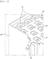
FIG. 1 is a perspective view schematically showing a battery cell connection structure according to an embodiment of the present invention and a battery module. -
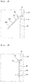
FIG. 2 is a sectional view schematically showing the battery cell connection structure according to the embodiment of the present invention. -
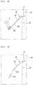
FIGS. 3 to 6 are sectional views schematically showing the operation process of the battery cell connection structure according to the embodiment of the present invention. -
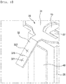
FIG. 7 is a sectional view schematically showing another example of the battery cell connection structure according to the embodiment of the present invention. -
FIG. 8 is a sectional view schematically showing another example of the battery cell connection structure according to the embodiment of the present invention. -
FIG. 9 is a sectional view schematically showing a further example of the battery cell connection structure according to the embodiment of the present invention. - Hereinafter, a battery cell connection structure and method according to embodiments of the present invention will be described with reference to the accompanying drawings.
- As shown in
FIG. 1 , a battery module, to which a battery cell connection structure according to an embodiment of the present invention is applied, includes a plurality ofbattery cells 10 and aframe 20 in which the plurality ofbattery cells 10 are loaded. - The battery cell connection structure according to the embodiment of the present invention serves to connect the plurality of
battery cells 10, loaded in theframe 20, to theframe 20. The cell connection structure may include aconnection member 30, which is connected to the plurality ofbattery cells 10 and which is coupled to theframe 20, and afixing portion 40, which is provided at theframe 20 and to which theconnection member 30 is fixed. - The
fixing portion 40, which is the portion to which theconnection member 30 is coupled, may be integrally formed with the frame, or may be manufactured separately from theframe 20 and may then be attached to theframe 20 by bolting, riveting, welding, etc. - The
connection member 30 serves to electrically connect the plurality ofbattery cells 10 to each other. To this end, theconnection member 30 may includeterminal portions 37 connected to electrodes of the plurality ofbattery cells 10. - The
connection member 30 may include aconnection portion 31, which is connected to the plurality ofbattery cells 10, and acoupling portion 32 extending from theconnection portion 31, thecoupling portion 32 being coupled to theframe 20. Theterminal portions 37, which are electrically connected to the plurality ofbattery cells 10, may be provided at theconnection portion 31. - The
coupling portion 32 is fixed to thefixing portion 40 of theframe 20. For example, thecoupling portion 32 may be fixed to thefixing portion 40 of theframe 20 by any one of bolting, riveting, and welding. - As shown in
FIG. 2 , thecoupling portion 32 may be formed so as to be inclined at a predetermined angle A relative to theconnection portion 31. Thecoupling portion 32 may be formed so as to be inclined at an angle of about 90 degrees relative to theconnection portion 31. Consequently, thecoupling portion 32 may be formed so as to be inclined at an angle of about 45 degrees relative to thefixing portion 40 of theframe 20. Since thecoupling portion 32 is formed so as to be inclined at the predetermined angle A relative to theconnection portion 31, when thecoupling portion 32 is fastened to thefixing portion 40 using a fastening member F, such as a rivet or a bolt, (seeFIG. 3 ,4 , or6 ), mechanical interference between the fastening member F or a tool used to fasten the fastening member F and theframe 20 or thefixing portion 40 may be prevented. - The
coupling portion 32 may be provided with a plurality of couplingposition indication portions coupling portion 32 extends and which indicate the coupling position of thecoupling portion 32 at which thecoupling portion 32 is coupled to thefixing portion 40 of theframe 20. - The plurality of coupling
position indication portions coupling portion 32 when a worker couples thecoupling portion 32 to thefixing portion 40 of theframe 20 using the fastening member F. In another example, the plurality of couplingposition indication portions coupling portion 32 to thefixing portion 40 of theframe 20 using a welding machine. - In the drawings, the
coupling portion 32 is shown as having therein two couplingposition indication portions coupling portion 32 may be provided with three or more couplingposition indication portions - For example, as shown in
FIGS. 1 to 6 , each of the plurality of couplingposition indication portions position indication portions coupling portion 32 may be easily coupled to thefixing portion 40 of theframe 20. - In another example, as shown in
FIGS. 7 to 9 , each of the plurality of couplingposition indication portions position indication portions position indication portions position indication portions - As shown in
FIGS. 2 and 3 , the couplingposition indication portion 321 that is located at the outermost end of thecoupling portion 32 in the direction in which thecoupling portion 32 extends, among the plurality of couplingposition indication portions fixing portion 40 of theframe 20. - As shown in
FIG. 7 , the plurality of couplingposition indication portions position indication portions position indication portions position indication portions position indication portions position indication portion 321 that is located at the outermost end of thecoupling portion 32 in the direction in which thecoupling portion 32 extends, among the plurality of couplingposition indication portions portion 40 of theframe 20, it is possible to prevent the other couplingposition indication portion 322 from impeding the process in which the couplingposition indication portion 321 located at the outermost end is coupled to the fixingportion 40 of theframe 20. - Meanwhile, as shown in
FIG. 4 , the process of coupling the coupling position indication portion 321 (the first coupling position indication portion), which is located at the outermost end, to the fixingportion 40 of theframe 20 may fail due to damage to thecoupling portion 32 caused by a collision between the fastening member F and thecoupling portion 32, etc. during the process of coupling the coupling position indication portion 321 (the first coupling position indication portion), which is located at the outermost end, to the fixingportion 40 of theframe 20. - In this case, as shown in
FIG. 5 , the coupling position indication portion 321 (the first coupling position indication portion) that is located at the outermost end may be removed from thecoupling portion 32 by cutting. - Subsequently, as shown in
FIG. 6 , the coupling position indication portion 322 (the second coupling position indication portion) that is located at the outermost end of thecoupling portion 32 after the removal process described above may be coupled to the fixingportion 40 of theframe 20. - Meanwhile,
FIGS. 5 and6 show that the process of removing the coupling position indication portion 321 (the first coupling position indication portion) from thecoupling portion 32 by cutting is performed and then the process of coupling the coupling position indication portion 322 (the second coupling position indication portion) to the fixingportion 40 of theframe 20 is performed. However, the present invention is not limited thereto. For example, the process of coupling the coupling position indication portion 322 (the second coupling position indication portion) to the fixingportion 40 of theframe 20 may be performed, and then the process of removing the coupling position indication portion 321 (the first coupling position indication portion), which is defective, from thecoupling portion 32 by cutting may be performed. - In the battery cell connection structure and method according to the embodiments of the present invention described above, even in the case in which the process of coupling the outermost end (the first coupling position indication portion 321) of the
coupling portion 32 of theconnection member 30 to theframe 20 fails, the outermost end (the first coupling position indication portion 321) of thecoupling portion 32 may be removed by cutting, and then a newly formed outermost end (the second coupling position indication portion 322) of thecoupling portion 32 may be coupled to theframe 20. Even in the case in which the process of coupling theconnection member 30 to theframe 20 fails, therefore, theconnection member 30 may be coupled to theframe 20 without completely disassembling the battery module. - In the case in which the process of coupling the outermost end (the first coupling position indication portion 321) of the
coupling portion 32 of theconnection member 30 to theframe 20 fails, as shown inFIG. 8 , a cuttingmark 325 is preferably provided between the plurality of couplingposition indication portions position indication portions coupling portion 32, the cuttingmark 325 may be made between a pair of adjacent couplingposition indication portions mark 325 is made between the pair of adjacent couplingposition indication portions mark 325 while checking the cuttingmark 325 at the time of cutting the outermost end (the first coupling position indication portion 321), whereby it is possible to accurately remove the outermost end (the first coupling position indication portion 321) by cutting. - In the case in which the process of coupling the outermost end (the first coupling position indication portion 321) of the
coupling portion 32 of theconnection member 30 to theframe 20 fails, as shown inFIG. 9 , a cuttinggroove 327 is preferably formed between the plurality of couplingposition indication portions position indication portions coupling portion 32, the cuttinggroove 327 may be formed between a pair of adjacent couplingposition indication portions groove 327 is formed between the pair of adjacent couplingposition indication portions groove 327 when the worker cuts the outermost end (the first coupling position indication portion 321). - Although the preferred embodiments of the present invention have been described by way of illustration, the scope of the present invention is not limited to the specific embodiments described herein, and the present invention can be appropriately modified within the category described in the claims.
-
- 10: Battery cell
- 20: Frame
- 30: Connection member
- 31: Connection portion
- 32: Coupling portion
- 40: Fixing portion
- In the battery cell connection structure and method according to the embodiments of the present invention, even in the case in which the process of coupling the outermost end (the first coupling position indication portion) of the coupling portion of the connection member, which connects the plurality of battery cells, to the frame fails, the outermost end (the first coupling position indication portion) of the coupling portion may be removed by cutting, and then a newly formed outermost end (the second coupling position indication portion) of the coupling portion may be coupled to the frame. Even in the case in which the process of coupling the connection member to the frame fails, therefore, the connection member may be coupled to the frame without completely disassembling a battery module.
Claims (13)
- A battery cell connection structure comprising a connection member configured to connect a plurality of battery cells loaded in a frame to the frame, wherein
the connection member comprises:a connection portion configured to be connected to the plurality of battery cells loaded in the frame; anda coupling portion extending from the connection portion, the coupling portion being configured to be coupled to the frame, andthe coupling portion is provided with a plurality of coupling position indication portions arranged in a line in a direction in which the coupling portion extends, the plurality of coupling position indication portions being configured to indicate a coupling position of the coupling portion at which the coupling portion is coupled to the frame. - The battery cell connection structure according to claim 1, wherein the coupling portion is inclined at a predetermined angle relative to the connection portion.
- The battery cell connection structure according to claim 1, wherein each of the coupling position indication portions is configured as any one of a concave recess, a protrusion, and a mark.
- The battery cell connection structure according to claim 1, wherein
the coupling portion is coupled to the frame using a fastening member, and
each of the coupling position indication portions is a through-hole, through which the fastening member is inserted. - The battery cell connection structure according to claim 1, wherein a coupling position indication portion located at an outermost end of the coupling portion in the direction in which the coupling portion extends, among the plurality of coupling position indication portions, is coupled to the frame.
- The battery cell connection structure according to claim 1, wherein at least a pair of coupling position indication portions, among the plurality of coupling position indication portions, are formed so as to have a predetermined angle therebetween.
- The battery cell connection structure according to claim 1, wherein a cutting mark is made between a pair of adjacent coupling position indication portions, among the plurality of coupling position indication portions.
- The battery cell connection structure according to claim 1, wherein a cutting groove is formed between a pair of adjacent coupling position indication portions, among the plurality of coupling position indication portions.
- The battery cell connection structure according to claim 1, wherein each of the coupling position indication portions is coupled to the frame by any one of bolting, riveting, and welding.
- A battery module comprising a battery cell connected using the battery cell connection structure according to any one of claims 1 to 9.
- A battery cell connection method using a battery cell connection structure comprising a connection member configured to connect a plurality of battery cells loaded in a frame to the frame, the connection member comprising: a connection portion configured to be connected to the plurality of battery cells loaded in the frame; and a coupling portion extending from the connection portion, the coupling portion being configured to be coupled to the frame, the coupling portion being provided with a plurality of coupling position indication portions arranged in a line in a direction in which the coupling portion extends, the plurality of coupling position indication portions being configured to indicate a coupling position of the coupling portion at which the coupling portion is coupled to the frame, wherein the battery cell connection method comprises:(a) coupling a first coupling position indication portion, located at an outermost end of the coupling portion in the direction in which the coupling portion extends, among the plurality of coupling position indication portions, to the frame;(b) in a case in which a process of coupling the first coupling position indication portion to the frame fails, removing the first coupling position indication portion from the coupling portion; and(c) coupling a second coupling position indication portion, adjacent to the first coupling position indication portion, to the frame.
- The battery cell connection method according to claim 11, wherein step (b) is performed before or after step (c) .
- A battery module comprising a battery cell connected using the battery cell connection method according to claim 11 or 12.
Applications Claiming Priority (2)
| Application Number | Priority Date | Filing Date | Title |
|---|---|---|---|
| KR1020180124459A KR102438383B1 (en) | 2018-10-18 | 2018-10-18 | Structure and method for connecting battery cell |
| PCT/KR2019/013459 WO2020080777A1 (en) | 2018-10-18 | 2019-10-15 | Battery cell connection structure and method |
Publications (3)
| Publication Number | Publication Date |
|---|---|
| EP3758098A1 true EP3758098A1 (en) | 2020-12-30 |
| EP3758098A4 EP3758098A4 (en) | 2021-05-26 |
| EP3758098B1 EP3758098B1 (en) | 2026-02-18 |
Family
ID=70282974
Family Applications (1)
| Application Number | Title | Priority Date | Filing Date |
|---|---|---|---|
| EP19873161.4A Active EP3758098B1 (en) | 2018-10-18 | 2019-10-15 | Battery cell connection structure and method |
Country Status (8)
| Country | Link |
|---|---|
| US (1) | US20210367300A1 (en) |
| EP (1) | EP3758098B1 (en) |
| JP (1) | JP7048847B2 (en) |
| KR (1) | KR102438383B1 (en) |
| CN (1) | CN111971818A (en) |
| ES (1) | ES3064340T3 (en) |
| TW (1) | TWI875708B (en) |
| WO (1) | WO2020080777A1 (en) |
Family Cites Families (14)
| Publication number | Priority date | Publication date | Assignee | Title |
|---|---|---|---|---|
| CN102668165B (en) * | 2009-10-01 | 2015-01-14 | 迪尔基金两合公司 | Device for electrically interconnecting cells in a battery pack by means of cell connectors and battery pack with such cell connectors |
| US8785781B2 (en) * | 2010-06-21 | 2014-07-22 | Samsung Sdi Co., Ltd. | Connecting tab of battery pack, coupling structure between the connecting tab and wire, and coupling method thereof |
| US8932741B2 (en) * | 2010-12-07 | 2015-01-13 | Volkswagen Ag | Conductor plate for a vehicle battery module |
| CN102903881B (en) * | 2011-07-29 | 2016-02-03 | 比亚迪股份有限公司 | A kind of for the connector between battery module and battery system |
| US20140234683A1 (en) * | 2013-02-19 | 2014-08-21 | Faster Faster, Inc. | Thermal Insulation of Battery Cells |
| KR102084098B1 (en) * | 2013-09-23 | 2020-03-04 | 삼성에스디아이 주식회사 | Battery module having holder |
| JP6292377B2 (en) * | 2013-12-02 | 2018-03-14 | 三菱自動車工業株式会社 | Battery cell fixing device |
| JP2015198071A (en) * | 2014-04-03 | 2015-11-09 | トヨタ自動車株式会社 | bus bar |
| JP6244279B2 (en) * | 2014-08-27 | 2017-12-06 | 株式会社Gsユアサ | Power storage device and method for manufacturing power storage device |
| KR101991925B1 (en) * | 2015-12-04 | 2019-06-21 | 주식회사 엘지화학 | Battery Module Comprising Cartridge Having Gripping Part |
| JPWO2017169729A1 (en) * | 2016-03-30 | 2019-02-14 | 三洋電機株式会社 | Battery pack |
| KR101934346B1 (en) * | 2016-11-11 | 2019-01-03 | 주식회사 아이티엠반도체 | Hetero electrodes plate apparatus of battery pack module and battery pack module |
| GB2560039B (en) * | 2017-02-28 | 2020-05-27 | Jaguar Land Rover Ltd | Battery cell housing |
| KR20180124459A (en) | 2017-05-12 | 2018-11-21 | 한국전기연구원 | Ohmic contact and ohmic contact between semiconductor and metal and method for forming the same |
-
2018
- 2018-10-18 KR KR1020180124459A patent/KR102438383B1/en active Active
-
2019
- 2019-08-26 TW TW108130448A patent/TWI875708B/en active
- 2019-10-15 JP JP2020550094A patent/JP7048847B2/en active Active
- 2019-10-15 CN CN201980025968.0A patent/CN111971818A/en active Pending
- 2019-10-15 ES ES19873161T patent/ES3064340T3/en active Active
- 2019-10-15 WO PCT/KR2019/013459 patent/WO2020080777A1/en not_active Ceased
- 2019-10-15 EP EP19873161.4A patent/EP3758098B1/en active Active
- 2019-10-15 US US17/058,285 patent/US20210367300A1/en active Pending
Also Published As
| Publication number | Publication date |
|---|---|
| JP2021516855A (en) | 2021-07-08 |
| US20210367300A1 (en) | 2021-11-25 |
| TW202017229A (en) | 2020-05-01 |
| JP7048847B2 (en) | 2022-04-06 |
| EP3758098A4 (en) | 2021-05-26 |
| KR102438383B1 (en) | 2022-08-31 |
| EP3758098B1 (en) | 2026-02-18 |
| TWI875708B (en) | 2025-03-11 |
| KR20200043720A (en) | 2020-04-28 |
| CN111971818A (en) | 2020-11-20 |
| ES3064340T3 (en) | 2026-04-24 |
| WO2020080777A1 (en) | 2020-04-23 |
Similar Documents
| Publication | Publication Date | Title |
|---|---|---|
| EP3613535B1 (en) | Laser welding jig and laser welding device comprising same | |
| US12263606B2 (en) | Battery, power utilization device, welding deviation detection device and welding deviation detection method | |
| KR102222887B1 (en) | Battery module | |
| KR101201748B1 (en) | Battery modual | |
| US9660230B2 (en) | Battery pack having end plates | |
| EP2654099B1 (en) | Battery module and battery pack | |
| CN106104854B (en) | Busbar module, battery monitoring module and battery module | |
| EP2461392B1 (en) | Battery module | |
| EP2544261A1 (en) | Battery connection assembly | |
| KR20160016613A (en) | Energy storage apparatus | |
| EP3154108A1 (en) | Battery module and battery pack including same | |
| EP3930084B1 (en) | Connection assembly, battery module, battery pack, device, and manufacturing method | |
| EP4723359A1 (en) | Battery cell, battery, and electrical device | |
| KR20200077634A (en) | Battery module | |
| KR102019472B1 (en) | Battery module and battery pack including the same | |
| KR20170052327A (en) | Battery module | |
| KR20150106735A (en) | Battery pack | |
| JP6808283B2 (en) | Batteries | |
| EP3758098B1 (en) | Battery cell connection structure and method | |
| EP3712981A1 (en) | Battery module | |
| KR101829092B1 (en) | Battery Cell Seating Guide JIG And Method For Seating Battery Cell At End Plate | |
| CN223347956U (en) | Flexible circuit board, battery pack and electric equipment | |
| CN219350871U (en) | Wiring device applied to battery breaking unit, connecting piece and battery pack | |
| WO2025107309A1 (en) | Battery pack and electrical device |
Legal Events
| Date | Code | Title | Description |
|---|---|---|---|
| STAA | Information on the status of an ep patent application or granted ep patent |
Free format text: STATUS: THE INTERNATIONAL PUBLICATION HAS BEEN MADE |
|
| PUAI | Public reference made under article 153(3) epc to a published international application that has entered the european phase |
Free format text: ORIGINAL CODE: 0009012 |
|
| STAA | Information on the status of an ep patent application or granted ep patent |
Free format text: STATUS: REQUEST FOR EXAMINATION WAS MADE |
|
| 17P | Request for examination filed |
Effective date: 20200922 |
|
| AK | Designated contracting states |
Kind code of ref document: A1 Designated state(s): AL AT BE BG CH CY CZ DE DK EE ES FI FR GB GR HR HU IE IS IT LI LT LU LV MC MK MT NL NO PL PT RO RS SE SI SK SM TR |
|
| AX | Request for extension of the european patent |
Extension state: BA ME |
|
| REG | Reference to a national code |
Ref country code: DE Ref legal event code: R079 Free format text: PREVIOUS MAIN CLASS: H01M0002200000 Ipc: H01M0050200000 |
|
| A4 | Supplementary search report drawn up and despatched |
Effective date: 20210423 |
|
| RIC1 | Information provided on ipc code assigned before grant |
Ipc: H01M 50/20 20210101AFI20210419BHEP Ipc: H01M 50/50 20210101ALI20210419BHEP |
|
| RAP1 | Party data changed (applicant data changed or rights of an application transferred) |
Owner name: LG ENERGY SOLUTION LTD. |
|
| DAV | Request for validation of the european patent (deleted) | ||
| DAX | Request for extension of the european patent (deleted) | ||
| RAP3 | Party data changed (applicant data changed or rights of an application transferred) |
Owner name: LG ENERGY SOLUTION, LTD. |
|
| STAA | Information on the status of an ep patent application or granted ep patent |
Free format text: STATUS: EXAMINATION IS IN PROGRESS |
|
| 17Q | First examination report despatched |
Effective date: 20240325 |
|
| REG | Reference to a national code |
Ref country code: DE Ipc: H01M0050204000 Ref country code: DE Ref legal event code: R079 Ref document number: 602019081596 Country of ref document: DE Free format text: PREVIOUS MAIN CLASS: H01M0050200000 Ipc: H01M0050204000 |
|
| GRAP | Despatch of communication of intention to grant a patent |
Free format text: ORIGINAL CODE: EPIDOSNIGR1 |
|
| STAA | Information on the status of an ep patent application or granted ep patent |
Free format text: STATUS: GRANT OF PATENT IS INTENDED |
|
| RIC1 | Information provided on ipc code assigned before grant |
Ipc: H01M 50/204 20210101AFI20251002BHEP Ipc: H01M 50/262 20210101ALI20251002BHEP Ipc: H01M 50/264 20210101ALI20251002BHEP Ipc: H01M 50/50 20210101ALI20251002BHEP Ipc: H01M 50/503 20210101ALI20251002BHEP Ipc: H01M 50/517 20210101ALI20251002BHEP |
|
| INTG | Intention to grant announced |
Effective date: 20251023 |
|
| P01 | Opt-out of the competence of the unified patent court (upc) registered |
Free format text: CASE NUMBER: UPC_APP_0012121_3758098/2025 Effective date: 20251105 |
|
| GRAS | Grant fee paid |
Free format text: ORIGINAL CODE: EPIDOSNIGR3 |
|
| GRAA | (expected) grant |
Free format text: ORIGINAL CODE: 0009210 |
|
| STAA | Information on the status of an ep patent application or granted ep patent |
Free format text: STATUS: THE PATENT HAS BEEN GRANTED |
|
| AK | Designated contracting states |
Kind code of ref document: B1 Designated state(s): AL AT BE BG CH CY CZ DE DK EE ES FI FR GB GR HR HU IE IS IT LI LT LU LV MC MK MT NL NO PL PT RO RS SE SI SK SM TR |
|
| REG | Reference to a national code |
Ref country code: CH Ref legal event code: F10 Free format text: ST27 STATUS EVENT CODE: U-0-0-F10-F00 (AS PROVIDED BY THE NATIONAL OFFICE) Effective date: 20260218 Ref country code: GB Ref legal event code: FG4D |
|
| REG | Reference to a national code |
Ref country code: IE Ref legal event code: FG4D |
|
| REG | Reference to a national code |
Ref country code: DE Ref legal event code: R096 Ref document number: 602019081596 Country of ref document: DE |
|
| REG | Reference to a national code |
Ref country code: ES Ref legal event code: FG2A Ref document number: 3064340 Country of ref document: ES Kind code of ref document: T3 Effective date: 20260424 |