EP2544261A1 - Battery connection assembly - Google Patents
Battery connection assembly Download PDFInfo
- Publication number
- EP2544261A1 EP2544261A1 EP11750621A EP11750621A EP2544261A1 EP 2544261 A1 EP2544261 A1 EP 2544261A1 EP 11750621 A EP11750621 A EP 11750621A EP 11750621 A EP11750621 A EP 11750621A EP 2544261 A1 EP2544261 A1 EP 2544261A1
- Authority
- EP
- European Patent Office
- Prior art keywords
- coupling unit
- coupling
- positioning member
- unit
- individual
- Prior art date
- Legal status (The legal status is an assumption and is not a legal conclusion. Google has not performed a legal analysis and makes no representation as to the accuracy of the status listed.)
- Withdrawn
Links
Images


Classifications
-
- H—ELECTRICITY
- H01—ELECTRIC ELEMENTS
- H01R—ELECTRICALLY-CONDUCTIVE CONNECTIONS; STRUCTURAL ASSOCIATIONS OF A PLURALITY OF MUTUALLY-INSULATED ELECTRICAL CONNECTING ELEMENTS; COUPLING DEVICES; CURRENT COLLECTORS
- H01R11/00—Individual connecting elements providing two or more spaced connecting locations for conductive members which are, or may be, thereby interconnected, e.g. end pieces for wires or cables supported by the wire or cable and having means for facilitating electrical connection to some other wire, terminal, or conductive member, blocks of binding posts
- H01R11/11—End pieces or tapping pieces for wires, supported by the wire and for facilitating electrical connection to some other wire, terminal or conductive member
- H01R11/28—End pieces consisting of a ferrule or sleeve
- H01R11/281—End pieces consisting of a ferrule or sleeve for connections to batteries
- H01R11/288—Interconnections between batteries
-
- H—ELECTRICITY
- H01—ELECTRIC ELEMENTS
- H01M—PROCESSES OR MEANS, e.g. BATTERIES, FOR THE DIRECT CONVERSION OF CHEMICAL ENERGY INTO ELECTRICAL ENERGY
- H01M50/00—Constructional details or processes of manufacture of the non-active parts of electrochemical cells other than fuel cells, e.g. hybrid cells
- H01M50/20—Mountings; Secondary casings or frames; Racks, modules or packs; Suspension devices; Shock absorbers; Transport or carrying devices; Holders
- H01M50/204—Racks, modules or packs for multiple batteries or multiple cells
-
- H—ELECTRICITY
- H01—ELECTRIC ELEMENTS
- H01M—PROCESSES OR MEANS, e.g. BATTERIES, FOR THE DIRECT CONVERSION OF CHEMICAL ENERGY INTO ELECTRICAL ENERGY
- H01M50/00—Constructional details or processes of manufacture of the non-active parts of electrochemical cells other than fuel cells, e.g. hybrid cells
- H01M50/50—Current conducting connections for cells or batteries
- H01M50/502—Interconnectors for connecting terminals of adjacent batteries; Interconnectors for connecting cells outside a battery casing
- H01M50/521—Interconnectors for connecting terminals of adjacent batteries; Interconnectors for connecting cells outside a battery casing characterised by the material
- H01M50/522—Inorganic material
-
- Y—GENERAL TAGGING OF NEW TECHNOLOGICAL DEVELOPMENTS; GENERAL TAGGING OF CROSS-SECTIONAL TECHNOLOGIES SPANNING OVER SEVERAL SECTIONS OF THE IPC; TECHNICAL SUBJECTS COVERED BY FORMER USPC CROSS-REFERENCE ART COLLECTIONS [XRACs] AND DIGESTS
- Y02—TECHNOLOGIES OR APPLICATIONS FOR MITIGATION OR ADAPTATION AGAINST CLIMATE CHANGE
- Y02E—REDUCTION OF GREENHOUSE GAS [GHG] EMISSIONS, RELATED TO ENERGY GENERATION, TRANSMISSION OR DISTRIBUTION
- Y02E60/00—Enabling technologies; Technologies with a potential or indirect contribution to GHG emissions mitigation
- Y02E60/10—Energy storage using batteries
Definitions
- the present invention relates to a battery connecting assembly.
- electric cells having positive and negative electrode terminals are arranged in line.
- the electrode terminals of electric cells that are adjacent to each other are connected through a connecting member (bus bar) to connect a plurality of electric cells in series or parallel (See Patent Document 1).
- Patent Document 1 Japanese Unexamined Patent Publication No. 11-067184
- the inventors of the present invention have come to conceive a battery connecting assembly having resin units corresponding to the number of connecting members, and connecting these units to each other to attach a plurality of electric cells thereto, instead of a battery connection plate where a plurality of connecting members are integrally molded.
- Electrodes arranged in multiple lines To connect the plurality of batteries in series or parallel, the electrode terminals arranged in the plurality of lines may need to be connected by each line.
- a specific description will be made as follows. In a case that a plurality of electric cells is connected in series or parallel, electrode terminals of every two adjacent electric cells are connected through a connecting member in one line. On the other hand, in the other line, electrode terminals of every two adjacent electric cells are connected through a connecting member in a manner that the two adjacent electric cells of the other line are displaced by one electric cell with respect to the two adjacent connected electric cells of the one line.
- the battery connecting assembly of one line must be installed in a place displaced from the battery connecting assembly of the other line by one electric cell. After the battery connecting assembly is connected to one line, if the installation position of the other battery connecting assembly to the other line is made wrongly, it is concerned that not only the electric cells cannot be connected in series or the like, but also the electric cells may be short-circuited.
- the present invention was made in view of the foregoing circumstances. It is an object of the present invention to provide a battery connecting assembly configured to prevent an error in the installation position, and the like.
- a battery connecting assembly accommodating a plurality of connecting members connecting electrode terminals adjacent to each other in an electrode terminal group of each line in a battery module, in which a plurality of electric cells each having a positive electrode terminal and a negative electrode terminal is aligned to form the plurality of electrode terminal groups of the plurality of lines, including: a first coupling unit having a plurality of individual units each accommodating the connecting member, and configured by coupling the individual units adjacent to each other; a second coupling unit having a plurality of individual units each accommodating the connecting member, and configured by coupling the individual units adjacent to each other, and arranged side by side with the first coupling unit; and a positioning member connected to the first coupling unit and the second coupling unit to position the first coupling unit and the second coupling unit relatively.
- the battery connecting assembly prevents a short circuit and the like due to, for example, a wrong assembly position of the second coupling unit with respect to the first coupling unit because the positions of the first coupling unit and the second coupling unit are defined by the positioning member.
- a battery connecting assembly 20 of this embodiment connects a plurality of electric cells 10 in a battery module M having a group of electric cells, in which the plurality of electric cells 10 each having positive and negative electrode terminals 12A and 12B are aligned.
- the battery module M having this battery connecting assembly 20 is used for, for example, a driving source of an electric car, hybrid car or the like.
- the description is made based on a rule that the right and left direction (width direction) refers to FIG. 18 , and the front side and the rear side refer to the upper side and the lower side of FIG. 18 , respectively.
- the battery module M includes: the plurality of electric cells 10; a voltage detecting line W detecting the voltage of the electric cells 10; and the battery connecting assembly 20 accommodating a plurality of connecting members 13 connecting adjacent electrode terminals 12A and 12B.
- Each electric cell 10 has: an electric cell body 11 accommodating an electric power generation element (not shown); and electrode terminals 12A and 12B having a bolt shape vertically projecting from the top surface of the electric cell body 11 (the positive electrode is indicated as 12A and the negative electrode is indicated as 12B).
- the electrode terminals 12A and 12B are provided on the front side and rear side of the top surface of each electric cell body 11 with the polarities opposite to each other.
- the electric cells 10 are arranged such that the orientation of each electric cell 10 is opposite to that of an electric cell 10 adjacent thereto so as to have a configuration where the electrode terminals 12A and 12B are arranged adjacent to each other.
- the plurality of electric cells 10 is fixed by a retaining plate.
- the voltage detecting line W is a cable, in which the core is covered with an insulation layer, and this insulation layer is stripped at the terminal to expose the core.
- the cable is then connected to a battery ECU (not shown).
- This battery ECU has a microcomputer, elements and the like, and has a known configuration having functions of detecting the voltage, current, temperature and the like of the electric cells 10, of conducting charge and discharge control of each electric cell 10, and the like.
- the battery connecting assembly 20 includes: a first coupling unit 21, in which a plurality of individual units 20A is placed (coupled to each other) in one line in the right and left direction; a second coupling unit 22, in which a plurality of individual units 20A is placed (coupled to each other) in one line in the right and left direction, and placed parallel to the first coupling unit 21; and a positioning member 40 positioning the first coupling unit 21 and the second coupling unit 22 relatively.
- each individual unit 20A has an identical shape to one another. As shown in FIG. 4 , each individual unit 20A includes: a metal connecting member 13 connecting adj acent electrode terminals 12A and 12B; and a resin body portion 26 accommodating the connecting member 13. In addition, each of the individual units 20A is mounted on the top surfaces of two (or predetermined number of) electric cells 10 adjacent to each other. The following descriptions will be made in a rule that the right and left direction of the individual unit 20A refers to FIG. 6 , and the front side and the rear side refer to the upper side and the lower side of FIG. 6 , respectively.
- the connecting member 13 is made of metal such as copper, copper alloy and stainless steel (SUS), and has a substantially rectangular plate shape having terminal insertion holes through which the electrode terminals 12A and 12B are inserted.
- a plate-shaped terminal portion 14 is placed on one side of the connecting member 13 in the right and left direction. The terminal portion 14 is crimped to the terminal of the voltage detecting line W, and has a rectangular shape with a terminal insertion hole at the center.
- the body portion 26 is made of synthetic resin such as PP.
- the body portion 26 includes: an accommodating portion 25 accommodating the connecting member 13; a ditch portion 30 extending to the front part of the accommodating portion 25, and having the voltage detecting line W routed therein; and a coupling portion 50 provided at four corners of the body portion and coupling to the body portion 26 of adjacent individual units 20A; and a locked portion 55 having a positioning member 40 (described later) to be locked at the rear end of the accommodating portion 25.
- the accommodating portion 25 has a bottom portion 23, on which the connection portion 13 is mounted, and a wall portion 24 rising from the edge of the bottom portion 23 so as to surround the connecting member 13.
- the bottom portion 23 has an opening formed substantially in its entirety, through which the electrode terminals 12A and 12B are inserted, and the bottom portion 23 connects the lower ends of the front and rear wall portions 24 at the middle portion in the width direction.
- the wall portion 24 prevents a short circuit due to contact of a tool and the like to the electrode terminals 12A and 12B or the connecting portion 13, and as shown in FIG. 4 , the wall portion 24 in the front is a dividing wall portion 24A formed higher than others.
- a pair of locking claws 24B projects from the proximal portion of the dividing wall portion 24A so as to increase their sizes toward the lower side in an inclined manner.
- the connecting member 13 placed on the bottom portion 23 is locked at the upper side thereof by the pair of locking claws 24B.
- a pair of partition walls 27 is provided inside the right and left wall portions 24, and the connecting member 13 is accommodated inside these partition walls 27 while the voltage detecting line W is drawn to the ditch portion 30 through the space between a partition wall 27 and a wall portion 24.
- the ditch portion 30 is defined by: the dividing wall portion 24A; a base plate 31 extending to the front side of the dividing wall portion 24A at the height of the wall portion 24 other than the dividing wall portion 24A; and a side wall portion 32 rising from the front edge of the base plate 31.
- an electric-wire retaining claw 33 projects from the top end of the side wall portion 32 toward the dividing wall portion 24A while a retaining projection portion 34 projects from the top end of the dividing wall portion 24A toward the side wall portion 32.
- a space for inserting the voltage detecting line W is formed between the electric-wire retaining claw 33 and the retaining projection portion 34, and the voltage detecting line W is inserted through this space to be retained within the ditch portion 30.
- the coupling portion 50 has two engaging portion 51 provided at the left end side (one side in the aligned direction), and two engaged portion 52 provided at the right end side (the other side in the aligned direction of the individual units 20A) and engaged with the engaging portions 51 of an adjacent individual unit 20A.
- Each engaging portion 51 includes: supporting proximal portions 51A projecting from the front end and the rear end in a rectangular parallelepiped shape; a shaft portion 51B cylindrically extending to the left (in the aligned direction) of the individual unit 20A from the supporting proximal 51A; and a flanged portion 51C having a disc shape and radially extending from the circumference of the shaft portion 51B at the end of the shaft portion 51B.
- each engaged portion 52 has an insertion recessed portion 53 projecting from the front end and the rear end in a rectangular parallelepiped shape.
- the insertion recessed portion 53 includes a shaft insertion hole having a substantially circular shape penetrating in the right and left direction, and a pair of engaging projection portions projecting inwardly at the upper part of the shaft insertion hole.
- the shaft insertion hole has a diameter sufficient to insert the shaft portion 51B of the engaging portion 51, and the dimension between the pair of engaging projection portions 53B is slightly smaller than the diameter of the shaft portion 51B.
- the locked portion 55 protrudes from the middle part of the rear of the body portion 26 in the right and left direction, and has a locking hole 56 penetrating in the upper and lower direction.
- the locking hole 56 opens with a substantially constant dimension other than both ends and has a U shape by cutting both ends toward the rear side.
- the hole wall 56A forming the front wall of the locking hole 56 is formed to be flush with the rear surface 20B of the individual unit 20A.
- the lower portion of the locked portion 55 has a fitting recessed portion 57 formed therein having a shape such that the positioning member matingly fits into the fitting recessed portion 57.
- the second coupling units 22 are arranged (coupled) in one line at a place corresponding to the locations of the electrode terminals 12A and 12B to be attached, and thereby the second coupling unit 22 is arranged spaced apart from the first coupling unit 21 by a certain distance in the front and rear direction.
- the individual units 20A of the second coupling unit 22 are arranged such that the locations of the individual units 20A are displaced by the width dimension of one electric cell 10 in the right and left direction.
- the second coupling unit 22 does not have positioning members 40 at both ends, and the number of individual units 20A is larger than the number of individual units 20A of the first coupling unit 21.
- Each individual unit 20A of the second coupling unit 22 has the same configuration as the individual unit 20A of the first coupling unit 21.
- the positioning member 40 is made of synthetic resin such as PP, and includes a first divided member 41 coupled to the left end side (one side) of the first coupling unit 21, and a second divided member 42 coupled to the right end side (the other side) of the first coupling unit 21.
- the first divided member 41 includes a dividing body portion 41A having a shape such that the individual unit 20A is divided by substantially half, and an extended locking portion 60 extending rearward from the divided body portion 41A in an arm shape and connected to the second coupling unit 22.
- the divided body portion 41A has a divided shape such that the right half of the individual unit 20A remains while the left half is cut out.
- the divided body portion 41A includes: an accommodating portion 43 accommodating a terminal portion 14; a ditch portion 47, in which the voltage detecting line W is routed; and an engaged portion 52 coupling with the body portion 26 of an adjacent unit 20A.
- One divided body portion 41A is mounted on the upper surface of one electric cell 10.
- the accommodating portion 43 has a bottom portion 44, and a wall portion 45 rising from the edge of the bottom portion 44 other than the left end side.
- the bottom portion 44 has an opening substantially in entirety of the bottom portion 23 other than the edge, through which the electrode terminal 12A is inserted.
- the wall portion 45 at the front side is a dividing wall portion 45A formed higher than others.
- a locking claw 45B protrudes from the proximal portion of the dividing wall portion 45A so as to increase their sizes toward the lower side in an inclined manner.
- the top surface of the terminal portion 14 placed on the bottom portion 44 is locked by the locking claw 45B.
- a partition wall 46 is provided inside of the wall portion 45 of the right side, and the terminal portion 14 is accommodated at the left side of the partition wall 46 while the voltage detecting line W is routed at the right side of the partition wall 46. Since the positioning member 40 does not connect electrode terminals 12A and 12B (because only one electrode terminal 12A is inserted into the accommodating portion 43), it is not provided with any connecting member 13.
- the ditch portion 47 is defined by: adividingwallportion 45A; a bottom plate 48 extending to the front of the dividing wall portion 45A at the height of the wall portion 45 other than the dividing wall portion 45A; and a side wall portion 49 rising from the front edge of the bottom plate 48.
- an electric-wire retaining claw 49A projects rearward from the top end of the side wall portion 49 while a retaining projection portion 45C projects forward from the top end of the dividing wall portion 45A.
- a space having a dimension sufficient to insert the voltage detecting line W is formed between the electric-wire retaining claw 49A and the retaining projection portion 45C, and the voltage detecting line W is inserted through this space to be retained within the ditch portion 47.
- the extended locking portion 60 has a U-shaped section where the top surface side defines a recessed portion.
- the extended locking portion 60 has an extended body portion 61 extending toward the second coupling unit 22, and an engaging projection part 65 rising perpendicularly from the distal end of the extended body portion 61.
- the extended body portion 61 has a bottom surface extending along (and flush with) the bottom surface of the divided body portion 41A.
- the extended body portion 61 includes: an extended proximal portion 62 linearly extending rearward; an inclined portion 63 inclined rightward (toward one side in the right and left direction) from the extended proximal portion 62 in accordance with the position of the locked portion 55 of an individual unit 20A to be connected; and an extended distal portion 64 again linearly extending rearward from the distal end of the inclined portion 63.
- the engaging projection part 65 is continued from the distal end of the extended distal portion 64, and has a projection height such that the distal end slightly penetrates the engaging hole 56 when inserted through the engaging hole 56 of the locked portion 55.
- Engaged portions 52 are provided at the front and rear ends of the right end side (at one side of the aligned direction) of the divided body portion 41A respectively, and both are engaged with the engaging portions 51 of an adjacent unit 20A.
- the engaged portion 52 of the first divided member 41 has a configuration identical with the engaged portion 52 of the individual unit 20A.
- the second divided member 42 is formed to be symmetrical with the first dividedmember 41.
- the second divided member 42 includes: a divided body portion 70 having a shape such that an individual unit 20A is divided by half; and an extended locking portion 80 integrally formed with the divided body portion 70 and extending rearward from the divided body portion 70 in an arm shape to be connected to the second coupling unit 22.
- the divided body portion 70 has a divided shape such that the right half of the individual unit 20A remains while the left half is cut out.
- the divided body portion 70 includes: an accommodating portion 71 accommodating a terminal portion 14; a ditch portion 72 in which the voltage detecting line W is routed; and an engaging portion 51 coupling the divided body portion 70 to the body portion 26 of an adjacent unit 20A.
- One divided body portion 70 is mounted on the top surface of one electric cell 10.
- the accommodating portion 71 has a bottom portion 73, and a wall portion 74 rising from the edge of the bottom portion 73 other than the right end side.
- the bottomportion 73 has an opening substantially in its entirety, through which the electrode terminal 12B is inserted, and the bottom portion 73 is formed to include the edge of the opening.
- the wall portion 74 at the front side is a dividing wall portion 74A formed higher than others.
- a locking claw 74B protrudes from the proximal portion of the dividing wall portion 74A so as to increase their sizes toward the lower side in an inclined manner.
- the top surface of the terminal portion 14 is locked to the locking claw 74B.
- a partition wall 75 is provided at the inner side of the wall portion 74 of the right side, and the terminal portion 14 is accommodated at the right side of the partition wall 46 while the voltage detecting line W is routed at the left side of the partition wall 46. Since the positioning member 40 does not connect electrode terminals 12A and 12B (since only one electrode terminal 12B is inserted into the accommodating portion 71), it is not provided with any connecting member 13.
- the ditchportion 72 is defined by: a dividing wall portion 74A; a bottom plate 77 extending to the front of the dividing wall portion 74A at the height of the wall portion 74 other than the dividing wall portion 74A; and a side wall portion 76 rising from the front edge of the bottom plate 77.
- An electric-wire retaining claw 76A protrudes rearward from the top end of the side wall portion 76 while a retaining projection portion 74C projects forward from the top end of the dividing wall portion 74A.
- a space sufficient to insert the voltage detecting line W is formed between the electric-wire retaining claw 76A and the retaining projection portion 74C, and the voltage detecting line W is inserted through this space to be retained within the ditch portion 72.
- the extended locking portion 80 has a U section where the top surface defines a recessed portion.
- the extended locking portion 80 has an extended body portion 81 extending toward the second coupling unit 22, and an engaging projection part 85 vertically rising from the distal end of the extended body portion 81.
- the extended body portion 81 has a bottom surface extending along (and flush with) the bottom surface of the divided body portion 41A.
- the extended body portion 81 includes: an extended proximal portion 82 linearly extending rearward; an inclined portion 83 connected to the extended proximal portion 82 and inclined leftward (toward one side in the right and left direction) from the extended proximal portion 82 in accordance with the position of the locked portion 55; and an extended distal portion 84 again linearly extending rearward from the distal end of the inclined portion 83.
- the engaging projection part 85 is continued from the distal end of the extended distal portion 84, and has a projection height such that the distal end slightly penetrates the engaging hole 56 when inserted through the engaging hole 56 of the locked portion 55.
- Engaging portions 51 are provided at the front and rear of the right end side (at one side of the aligned direction) of the divided body portion 70 respectively, and both are engaged with the engaged portions 52 of an adjacent individual unit 20A respectively.
- the engaged portion 51 of the second divided member 42 has a configuration identical with the engaged portion 51 of the individual unit 20A.
- the first coupling unit 21 including six (multiple) individual units 20A is formed by inserting the shaft portion 51B of the engaging portion 51 through the insertion recessed portion 53 of the engaged portion 52 to engage the engaging portion 51 with the engaged portion 52.
- the engaging portion 51 at one end side of the first coupling unit 21 is engaged with the engaged portion 52 of the first divided member 41 (positioning member) to be coupled, and the engaged portion 52 at the other end side of the first coupling unit 21 is engaged with the engaging portion 51 of the second divided member 42 (positioning member) to be coupled ( FIG. 15 ).
- the second coupling unit 22 including seven (multiple) individual units 20A is formed by engaging the engaging portion 51 with the engaged portion 52.
- the locking projection part 65 of the extended locking portion 60 in the first divided member 41 is inserted into the locking hole 56 of the locked portion 55 of the individual unit 20A at the left end in the second coupling unit 22, while the locking projection part 85 of the extended locking portion 80 in the second divided member 42 is inserted into the locking hole 56 of the locked portion 55 of the individual unit 20A at the right end in the second coupling unit 22.
- the battery connecting assembly 20 is formed ( FIG. 16 ).
- the connecting members 13 are accommodated in the accommodating portion 25, the cover of the terminal portion of the voltage detecting line W is peeled off in accordance with the number of units 20A to expose the tip ends of the core, the terminal portion 14 is crimped, and the terminal portion 14 is overlapped on the connecting member 13 to pass through the voltage detecting line W through the ditch portion 30 ( FIG. 1 ).
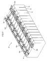
- All the electrode terminals 12A and 12B of the plurality of aligned electric cells 10 are integrally inserted into all the terminal insertion holes of the connecting members 13 accommodated in the battery connecting assembly 20, and the terminal insertion holes of the terminal portions 14 overlapped on these connecting members 13 ( FIG. 17 ).
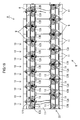
- nuts are screwed and fastened on electrode terminals 12A and 12B projecting from the terminal insertion holes of the terminal portions 14 and the connecting members 13. Once all of them are fastened, the battery module M is completed ( FIG. 18 ).
- both ends of the coupling units 21 and 22 are positioned by the positioning member 40, whereas in the second embodiment, as shown in FIG. 22 , portions of the coupling units other than both ends are also positioned by a positioning member 90, which is different from the positioning member 40.
- a description of the same structures as those of the first embodiment will be omitted using the same numerals.
- the positioning member 90 has a sectional U shape having a recessed portion. As shown in FIG. 19 , the positioning member 90 includes: an extended body portion 95 extending in a substantially crank shape in the front and rear direction; a first locking portion 91 locked to the locked portion 55 of an individual unit 20A included in the first coupling unit 87 at one end side of the extended body portion 95; and an second locking portion 92 locked to the locked portion 55 of the individual unit 20A included in the second coupling unit 88 at the other end side of the extended body portion 95.
- the extended body portion 95 has a sectional U shape having a recessed portion on the upper surface.
- the extended body portion 95 has extended proximal portions 96 and 96 linearly extending, and an inclined portion 97 coupling these extended proximal portions 62.
- the inclined portion 97 is inclined at an angle and distance such that one of the extended base portions 96 and 96 is arranged at a position corresponding to the locked portion 55 of the individual unit 20A included in the first coupling unit 87, while the other of the extended proximal portions 96 and 96 is arranged at a position corresponding to the locked portion 55 of the individual unit 20A include in the second coupling unit 88.
- the first locking portion 91 vertically rises from one end side of the extended body portion 95
- the second locking portion 92 vertically rises from the other end side of the extended body portion 95. Then, the positioning member 90 couples both the coupling units 87 and 88 to be locked between the locked portions 55 of individual units 20A placed in the substantially middle part of the first coupling unit 87 and the second coupling unit 88.
- the positioning member 90 includes the first locking portion 91 locked to the locked portion 55 of the individual unit 20A included in the first coupling unit 87, and the second locking portion 92 locked to the locked portion 55 of the individual unit 20A included in the second coupling unit 88, it is possible to position the first coupling unit 87 and the second coupling unit 88 with a simple configuration.
- the positioning member 90 as it is possible to add the positioning member 90 as needed, even when, for example, the number of units 20A included in each coupling unit becomes large, the first coupling unit 87 and the second coupling unit 88 can be stably positioned by adding the positioning member 90.
- the disclosed technique is a battery connecting assembly accommodating a plurality of connecting members connecting electrode terminals adjacent to each other in an electrode terminal group of each line in a battery module, in which a plurality of electric cells each having a positive electrode terminal and a negative electrode terminal is aligned to form the plurality of electrode terminal groups of the plurality of lines, including: a first coupling unit having a plurality of individual units each accommodating the connecting member, and configured by coupling the individual units adjacent to each other; a second coupling unit having a plurality of individual units each accommodating the connecting member, and configured by coupling the individual units adjacent to each other, and arranged side by side with the first coupling unit; and a positioning member connected to the first coupling unit and the second coupling unit to position the first coupling unit and the second coupling unit relatively (first means) .
- the battery connecting assembly prevents a short circuit and the like due to, for example, a wrong assembly position of the second coupling unit with respect to the first coupling unit because the positions of the first coupling unit and the second coupling unit are defined by the positioning member.
- the positioning member may be aligned at an end of the first coupling unit, and include an engaging portion engaging the positioning member to the first coupling unit, and an extended locking portion extending to the second coupling unit and locking the positioning member to an locked portion of the individual unit (second means).
- a positioning member 40 can be provided in a space where no individual unit is provided.
- both sides of both coupling units and are positioned it is possible to position the first coupling units the second coupling units more stably.
- the positioning member may include a first locking portion locked to a locked portion of the individual unit included in the first coupling unit, and a second locking portion locked to a locked portion of the individual unit included in the second coupling unit (third means).
- the configuration of the third means it is possible to position the first coupling unit and the second coupling unit with a simple configuration.
- the first coupling unit and the second coupling unit can be stably positioned by adding the positioning member.
Abstract
Description
- The present invention relates to a battery connecting assembly.
- In a battery module for electric cars or hybrid cars, electric cells having positive and negative electrode terminals are arranged in line. The electrode terminals of electric cells that are adjacent to each other are connected through a connecting member (bus bar) to connect a plurality of electric cells in series or parallel (See Patent Document 1).
- Patent Document 1: Japanese Unexamined Patent Publication No.
11-067184 - In the above configuration, as it is required to connect electrode terminals through a connecting member, it is required to attach a connecting member between each pair of electrode terminals, which is troublesome work. Therefore, it is conceivable to form a battery connection plate, in which a plurality of connectingmembers is integrally molded in resin, and to attach this battery connection plate to electric cells arranged in line to mount a plurality of connecting members at once.
- However, in a case of using the battery connection plate where the plurality of connecting members is integrally molded, the number of the electric cells increases. Therefore, as the size of a mold forming the battery connection plate becomes larger, this increases the cost. In addition, there has been a problem that, when the number of electric cells is changed, it is required to prepare another new mold having a length corresponding to the number of electric cells, and to form a battery connection plate having a different length, resulting in increasing the cost for forming the mold and the like, which then increases manufacturing costs.
- Therefore, the inventors of the present invention have come to conceive a battery connecting assembly having resin units corresponding to the number of connecting members, and connecting these units to each other to attach a plurality of electric cells thereto, instead of a battery connection plate where a plurality of connecting members are integrally molded.
- Positive and negative electrode terminals project from electric cells. Therefore, arranging the plurality of electric cells side by side makes the electrode terminals arranged in multiple lines. To connect the plurality of batteries in series or parallel, the electrode terminals arranged in the plurality of lines may need to be connected by each line. A specific description will be made as follows. In a case that a plurality of electric cells is connected in series or parallel, electrode terminals of every two adjacent electric cells are connected through a connecting member in one line. On the other hand, in the other line, electrode terminals of every two adjacent electric cells are connected through a connecting member in a manner that the two adjacent electric cells of the other line are displaced by one electric cell with respect to the two adjacent connected electric cells of the one line.
- Accordingly, at the time that electric cell connection assemblies each having a plurality of connecting members are installed line by line, the battery connecting assembly of one line must be installed in a place displaced from the battery connecting assembly of the other line by one electric cell. After the battery connecting assembly is connected to one line, if the installation position of the other battery connecting assembly to the other line is made wrongly, it is concerned that not only the electric cells cannot be connected in series or the like, but also the electric cells may be short-circuited.
- The present invention was made in view of the foregoing circumstances. It is an object of the present invention to provide a battery connecting assembly configured to prevent an error in the installation position, and the like.
- A battery connecting assembly accommodating a plurality of connecting members connecting electrode terminals adjacent to each other in an electrode terminal group of each line in a battery module, in which a plurality of electric cells each having a positive electrode terminal and a negative electrode terminal is aligned to form the plurality of electrode terminal groups of the plurality of lines, including: a first coupling unit having a plurality of individual units each accommodating the connecting member, and configured by coupling the individual units adjacent to each other; a second coupling unit having a plurality of individual units each accommodating the connecting member, and configured by coupling the individual units adjacent to each other, and arranged side by side with the first coupling unit; and a positioning member connected to the first coupling unit and the second coupling unit to position the first coupling unit and the second coupling unit relatively.
- According to the above configuration, the battery connecting assembly prevents a short circuit and the like due to, for example, a wrong assembly position of the second coupling unit with respect to the first coupling unit because the positions of the first coupling unit and the second coupling unit are defined by the positioning member.
- According to the present invention, a wrong installation position of a battery connecting assembly is prevented.
-
-
FIG. 1 is a plan view of a battery connecting assembly according to a first embodiment; -
FIG. 2 is a left side view of the battery connecting assembly; -
FIG. 3 is a right side view of the battery connecting assembly; -
FIG. 4 is a perspective view of an individual unit; -
FIG. 5 is a perspective view of the individual unit as viewed from a rear perspective; -
FIG. 6 is a plan view of the individual unit; -
FIG. 7 is a perspective view of a positioning member coupled to the left end side of the coupling unit; -
FIG. 8 is a plan view of the positioning member coupled to the left end side of the coupling unit; -
FIG. 9 is a side view of the positioning member coupled to the left end side of the coupling unit; -
FIG. 10 is a front view of the positioning member coupled to the left end side of the coupling unit; -
FIG. 11 is a perspective view of the positioning member coupled to the right end side of the coupling unit; -
FIG. 12 is a plan view of the positioning member coupled to the right end side of the coupling unit; -
FIG. 13 is a side view of the positioning member coupled to the right end side of the coupling unit; -
FIG. 14 is a front view of the positioning member coupled to the right end side of the coupling unit; -
FIG. 15 illustrates a state where the positioning member is coupled to the coupling unit; -
FIG. 16 is a perspective view of the battery connecting assembly; -
FIG. 17 illustrates a state where the battery connecting assembly is attached to a plurality of electric cells; -
FIG. 18 is a plan view of a battery module; -
FIG. 19 is a plan view of a positioning member according to a second embodiment; -
FIG. 20 is a side view of the positioning member; -
FIG. 21 is a front view of the positioning member; and -
FIG. 22 is a plan view of a battery module. -
- 10: Electric cell
- 12A: Positive electrode terminal (Electrode terminal)
- 12B: Negative electrode terminal (Electrode terminal)
- 13: Connecting member
- 20: Battery connecting assembly
- 20A: Individual unit
- 21, 87: First coupling unit
- 22, 88: Second coupling unit
- 25, 43, 71: Accommodating portion
- 26: Body portion
- 30, 47, 72: Ditch portion
- 40, 90: Positioning member
- 41: First divided member
- 41A, 70: Divided body portion
- 42: Second divided member
- 50: Coupling portion
- 51: Engaging portion
- 52: Engaged portion
- 55: Locked portion
- 56: Locking hole
- 60, 80: Extended locking portion
- 61, 81, 95: Extended body portion
- 65, 85: Locking projection part
- 91: First locking portion
- 92: Second locking portion
- M: Battery module
- W: Voltage detecting line
- A first embodiment of the present invention will be described with reference to
FIGs. 1 to 18 . As shown inFIG. 18 , abattery connecting assembly 20 of this embodiment connects a plurality ofelectric cells 10 in a battery module M having a group of electric cells, in which the plurality ofelectric cells 10 each having positive andnegative electrode terminals battery connecting assembly 20 is used for, for example, a driving source of an electric car, hybrid car or the like. Hereinafter, the description is made based on a rule that the right and left direction (width direction) refers toFIG. 18 , and the front side and the rear side refer to the upper side and the lower side ofFIG. 18 , respectively. - The battery module M includes: the plurality of
electric cells 10; a voltage detecting line W detecting the voltage of theelectric cells 10; and thebattery connecting assembly 20 accommodating a plurality of connectingmembers 13 connectingadjacent electrode terminals electric cell 10 has: anelectric cell body 11 accommodating an electric power generation element (not shown); andelectrode terminals - The
electrode terminals electric cell body 11 with the polarities opposite to each other. - In addition, the
electric cells 10 are arranged such that the orientation of eachelectric cell 10 is opposite to that of anelectric cell 10 adjacent thereto so as to have a configuration where theelectrode terminals electric cells 10 is fixed by a retaining plate. The voltage detecting line W is a cable, in which the core is covered with an insulation layer, and this insulation layer is stripped at the terminal to expose the core. The cable is then connected to a battery ECU (not shown). This battery ECU has a microcomputer, elements and the like, and has a known configuration having functions of detecting the voltage, current, temperature and the like of theelectric cells 10, of conducting charge and discharge control of eachelectric cell 10, and the like. - As shown in
FIG. 1 , thebattery connecting assembly 20 includes: afirst coupling unit 21, in which a plurality ofindividual units 20A is placed (coupled to each other) in one line in the right and left direction; asecond coupling unit 22, in which a plurality ofindividual units 20A is placed (coupled to each other) in one line in the right and left direction, and placed parallel to thefirst coupling unit 21; and a positioningmember 40 positioning thefirst coupling unit 21 and thesecond coupling unit 22 relatively. -
Individual units 20A have an identical shape to one another. As shown inFIG. 4 , eachindividual unit 20A includes: ametal connecting member 13 connecting adjacent electrode terminals resin body portion 26 accommodating the connectingmember 13. In addition, each of theindividual units 20A is mounted on the top surfaces of two (or predetermined number of)electric cells 10 adjacent to each other. The following descriptions will be made in a rule that the right and left direction of theindividual unit 20A refers toFIG. 6 , and the front side and the rear side refer to the upper side and the lower side ofFIG. 6 , respectively. - The connecting
member 13 is made of metal such as copper, copper alloy and stainless steel (SUS), and has a substantially rectangular plate shape having terminal insertion holes through which theelectrode terminals terminal portion 14 is placed on one side of the connectingmember 13 in the right and left direction. Theterminal portion 14 is crimped to the terminal of the voltage detecting line W, and has a rectangular shape with a terminal insertion hole at the center. - The
body portion 26 is made of synthetic resin such as PP. Thebody portion 26 includes: anaccommodating portion 25 accommodating the connectingmember 13; aditch portion 30 extending to the front part of theaccommodating portion 25, and having the voltage detecting line W routed therein; and acoupling portion 50 provided at four corners of the body portion and coupling to thebody portion 26 of adjacentindividual units 20A; and a lockedportion 55 having a positioning member 40 (described later) to be locked at the rear end of theaccommodating portion 25. - As shown in
FIG. 6 , theaccommodating portion 25 has abottom portion 23, on which theconnection portion 13 is mounted, and awall portion 24 rising from the edge of thebottom portion 23 so as to surround the connectingmember 13. Thebottom portion 23 has an opening formed substantially in its entirety, through which theelectrode terminals bottom portion 23 connects the lower ends of the front andrear wall portions 24 at the middle portion in the width direction. Thewall portion 24 prevents a short circuit due to contact of a tool and the like to theelectrode terminals portion 13, and as shown inFIG. 4 , thewall portion 24 in the front is a dividingwall portion 24A formed higher than others. - A pair of locking
claws 24B projects from the proximal portion of the dividingwall portion 24A so as to increase their sizes toward the lower side in an inclined manner. When accommodating the connectingmember 13, the connectingmember 13 placed on thebottom portion 23 is locked at the upper side thereof by the pair of lockingclaws 24B. A pair ofpartition walls 27 is provided inside the right and leftwall portions 24, and the connectingmember 13 is accommodated inside thesepartition walls 27 while the voltage detecting line W is drawn to theditch portion 30 through the space between apartition wall 27 and awall portion 24. - The
ditch portion 30 is defined by: the dividingwall portion 24A; abase plate 31 extending to the front side of the dividingwall portion 24A at the height of thewall portion 24 other than the dividingwall portion 24A; and aside wall portion 32 rising from the front edge of thebase plate 31. As shown inFIG. 5 , an electric-wire retaining claw 33 projects from the top end of theside wall portion 32 toward the dividingwall portion 24A while a retainingprojection portion 34 projects from the top end of the dividingwall portion 24A toward theside wall portion 32. A space for inserting the voltage detecting line W is formed between the electric-wire retaining claw 33 and the retainingprojection portion 34, and the voltage detecting line W is inserted through this space to be retained within theditch portion 30. Whenindividual units 20A are coupled in the right and left direction, theditch portions 30 of adjacentindividual units 20A are arranged in line. Therefore, the voltage detecting line W connected to the battery ECU and the like is accommodated therein. - The
coupling portion 50 has two engagingportion 51 provided at the left end side (one side in the aligned direction), and two engagedportion 52 provided at the right end side (the other side in the aligned direction of theindividual units 20A) and engaged with the engagingportions 51 of an adjacentindividual unit 20A. - Each engaging
portion 51 includes: supportingproximal portions 51A projecting from the front end and the rear end in a rectangular parallelepiped shape; ashaft portion 51B cylindrically extending to the left (in the aligned direction) of theindividual unit 20A from the supporting proximal 51A; and aflanged portion 51C having a disc shape and radially extending from the circumference of theshaft portion 51B at the end of theshaft portion 51B. On the other hand, each engagedportion 52 has an insertion recessedportion 53 projecting from the front end and the rear end in a rectangular parallelepiped shape. The insertion recessedportion 53 includes a shaft insertion hole having a substantially circular shape penetrating in the right and left direction, and a pair of engaging projection portions projecting inwardly at the upper part of the shaft insertion hole. - The shaft insertion hole has a diameter sufficient to insert the
shaft portion 51B of the engagingportion 51, and the dimension between the pair of engaging projection portions 53B is slightly smaller than the diameter of theshaft portion 51B. In this manner, when theindividual units 20A are coupled to each other, theshaft portion 51B of each engagingportion 51 is inserted between the pair of engaging projection portions of an insertion recessedportion 53, and the engagedportion 52 bends and deforms in a direction, in which the dimension between the pair of engaging projection portions slightly expands, and once theshaft portion 51B is inserted into the shaft insertion hole of the insertion recessedportion 53, the engagedportion 52 recovers the original shape, and the engagingportion 51 and the engagedportion 52 are engaged with each other. In this manner, in a state where theindividual units 20A are coupled to each other, removal of theshaft portion 51B in the up and down direction is restricted by locking theshaft portion 51B to the pair of engaging projection portion 53B while the removal in the right and left direction is restricted by sandwiching the engagedportion 52 between theflanged portion 51C and the engaging surface. - As shown in
FIG. 4 , the lockedportion 55 protrudes from the middle part of the rear of thebody portion 26 in the right and left direction, and has a lockinghole 56 penetrating in the upper and lower direction. The lockinghole 56 opens with a substantially constant dimension other than both ends and has a U shape by cutting both ends toward the rear side. Thehole wall 56A forming the front wall of the lockinghole 56 is formed to be flush with therear surface 20B of theindividual unit 20A. The lower portion of the lockedportion 55 has a fitting recessedportion 57 formed therein having a shape such that the positioning member matingly fits into the fitting recessedportion 57. - As shown in
FIG. 1 , thesecond coupling units 22 are arranged (coupled) in one line at a place corresponding to the locations of theelectrode terminals second coupling unit 22 is arranged spaced apart from thefirst coupling unit 21 by a certain distance in the front and rear direction. Also, theindividual units 20A of thesecond coupling unit 22 are arranged such that the locations of theindividual units 20A are displaced by the width dimension of oneelectric cell 10 in the right and left direction. In addition, thesecond coupling unit 22 does not havepositioning members 40 at both ends, and the number ofindividual units 20A is larger than the number ofindividual units 20A of thefirst coupling unit 21. Eachindividual unit 20A of thesecond coupling unit 22 has the same configuration as theindividual unit 20A of thefirst coupling unit 21. - The positioning
member 40 is made of synthetic resin such as PP, and includes a first dividedmember 41 coupled to the left end side (one side) of thefirst coupling unit 21, and a second dividedmember 42 coupled to the right end side (the other side) of thefirst coupling unit 21. As shown inFIG. 7 , the first dividedmember 41 includes a dividingbody portion 41A having a shape such that theindividual unit 20A is divided by substantially half, and anextended locking portion 60 extending rearward from the dividedbody portion 41A in an arm shape and connected to thesecond coupling unit 22. - The divided
body portion 41A has a divided shape such that the right half of theindividual unit 20A remains while the left half is cut out. The dividedbody portion 41A includes: anaccommodating portion 43 accommodating aterminal portion 14; aditch portion 47, in which the voltage detecting line W is routed; and an engagedportion 52 coupling with thebody portion 26 of anadjacent unit 20A. One dividedbody portion 41A is mounted on the upper surface of oneelectric cell 10. - The
accommodating portion 43 has abottom portion 44, and awall portion 45 rising from the edge of thebottom portion 44 other than the left end side. Thebottom portion 44 has an opening substantially in entirety of thebottom portion 23 other than the edge, through which theelectrode terminal 12A is inserted. Thewall portion 45 at the front side is a dividingwall portion 45A formed higher than others. - A locking
claw 45B protrudes from the proximal portion of the dividingwall portion 45A so as to increase their sizes toward the lower side in an inclined manner. When accommodating the connectingmember 13, the top surface of theterminal portion 14 placed on thebottom portion 44 is locked by the lockingclaw 45B. Apartition wall 46 is provided inside of thewall portion 45 of the right side, and theterminal portion 14 is accommodated at the left side of thepartition wall 46 while the voltage detecting line W is routed at the right side of thepartition wall 46. Since the positioningmember 40 does not connectelectrode terminals electrode terminal 12A is inserted into the accommodating portion 43), it is not provided with any connectingmember 13. - The
ditch portion 47 is defined by:adividingwallportion 45A; abottom plate 48 extending to the front of the dividingwall portion 45A at the height of thewall portion 45 other than the dividingwall portion 45A; and aside wall portion 49 rising from the front edge of thebottom plate 48. As shown inFIG. 8 , an electric-wire retaining claw 49A projects rearward from the top end of theside wall portion 49 while a retainingprojection portion 45C projects forward from the top end of the dividingwall portion 45A. A space having a dimension sufficient to insert the voltage detecting line W is formed between the electric-wire retaining claw 49A and the retainingprojection portion 45C, and the voltage detecting line W is inserted through this space to be retained within theditch portion 47. Whenindividual units 20A are coupled in the right and left direction, thisditch portion 47 is linked to theditch portion 30 of anadjacent unit 20A. - The
extended locking portion 60 has a U-shaped section where the top surface side defines a recessed portion. Theextended locking portion 60 has an extended body portion 61 extending toward thesecond coupling unit 22, and an engagingprojection part 65 rising perpendicularly from the distal end of the extended body portion 61. The extended body portion 61 has a bottom surface extending along (and flush with) the bottom surface of the dividedbody portion 41A. The extended body portion 61 includes: an extendedproximal portion 62 linearly extending rearward; an inclined portion 63 inclined rightward (toward one side in the right and left direction) from the extendedproximal portion 62 in accordance with the position of the lockedportion 55 of anindividual unit 20A to be connected; and an extendeddistal portion 64 again linearly extending rearward from the distal end of the inclined portion 63. - The engaging
projection part 65 is continued from the distal end of the extendeddistal portion 64, and has a projection height such that the distal end slightly penetrates the engaginghole 56 when inserted through the engaginghole 56 of the lockedportion 55. -
Engaged portions 52 are provided at the front and rear ends of the right end side (at one side of the aligned direction) of the dividedbody portion 41A respectively, and both are engaged with the engagingportions 51 of anadjacent unit 20A. The engagedportion 52 of the first dividedmember 41 has a configuration identical with the engagedportion 52 of theindividual unit 20A. - As shown in
FIG. 11 , the second dividedmember 42 is formed to be symmetrical with thefirst dividedmember 41. The second dividedmember 42 includes: a dividedbody portion 70 having a shape such that anindividual unit 20A is divided by half; and anextended locking portion 80 integrally formed with the dividedbody portion 70 and extending rearward from the dividedbody portion 70 in an arm shape to be connected to thesecond coupling unit 22. The dividedbody portion 70 has a divided shape such that the right half of theindividual unit 20A remains while the left half is cut out. The dividedbody portion 70 includes: anaccommodating portion 71 accommodating aterminal portion 14; aditch portion 72 in which the voltage detecting line W is routed; and an engagingportion 51 coupling the dividedbody portion 70 to thebody portion 26 of anadjacent unit 20A. One dividedbody portion 70 is mounted on the top surface of oneelectric cell 10. - The
accommodating portion 71 has abottom portion 73, and awall portion 74 rising from the edge of thebottom portion 73 other than the right end side. Thebottomportion 73 has an opening substantially in its entirety, through which theelectrode terminal 12B is inserted, and thebottom portion 73 is formed to include the edge of the opening. Thewall portion 74 at the front side is a dividingwall portion 74A formed higher than others. - A locking
claw 74B protrudes from the proximal portion of the dividingwall portion 74A so as to increase their sizes toward the lower side in an inclined manner. When theterminal portion 14 is mounted on thebottomportion 73, the top surface of theterminal portion 14 is locked to the lockingclaw 74B. As shown inFIG. 12 , apartition wall 75 is provided at the inner side of thewall portion 74 of the right side, and theterminal portion 14 is accommodated at the right side of thepartition wall 46 while the voltage detecting line W is routed at the left side of thepartition wall 46. Since the positioningmember 40 does not connectelectrode terminals electrode terminal 12B is inserted into the accommodating portion 71), it is not provided with any connectingmember 13. - The
ditchportion 72 is defined by: a dividingwall portion 74A; abottom plate 77 extending to the front of the dividingwall portion 74A at the height of thewall portion 74 other than the dividingwall portion 74A; and aside wall portion 76 rising from the front edge of thebottom plate 77. An electric-wire retaining claw 76A protrudes rearward from the top end of theside wall portion 76 while a retainingprojection portion 74C projects forward from the top end of the dividingwall portion 74A. A space sufficient to insert the voltage detecting line W is formed between the electric-wire retaining claw 76A and the retainingprojection portion 74C, and the voltage detecting line W is inserted through this space to be retained within theditch portion 72. When the second dividedmember 42 and theindividual unit 20A are coupled in the right and left direction, theditch portion 72 of the second dividedmember 42 and theditch portion 30 of theindividual unit 20A are arranged in line. - The
extended locking portion 80 has a U section where the top surface defines a recessed portion. Theextended locking portion 80 has an extended body portion 81 extending toward thesecond coupling unit 22, and an engagingprojection part 85 vertically rising from the distal end of the extended body portion 81. The extended body portion 81 has a bottom surface extending along (and flush with) the bottom surface of the dividedbody portion 41A. The extended body portion 81 includes: an extendedproximal portion 82 linearly extending rearward; an inclined portion 83 connected to the extendedproximal portion 82 and inclined leftward (toward one side in the right and left direction) from the extendedproximal portion 82 in accordance with the position of the lockedportion 55; and an extendeddistal portion 84 again linearly extending rearward from the distal end of the inclined portion 83. The engagingprojection part 85 is continued from the distal end of the extendeddistal portion 84, and has a projection height such that the distal end slightly penetrates the engaginghole 56 when inserted through the engaginghole 56 of the lockedportion 55. - Engaging
portions 51 are provided at the front and rear of the right end side (at one side of the aligned direction) of the dividedbody portion 70 respectively, and both are engaged with the engagedportions 52 of an adjacentindividual unit 20A respectively. The engagedportion 51 of the second dividedmember 42 has a configuration identical with the engagedportion 51 of theindividual unit 20A. - Next, a description will be made of assembly of the
battery connecting assembly 20. Thefirst coupling unit 21 including six (multiple)individual units 20A is formed by inserting theshaft portion 51B of the engagingportion 51 through the insertion recessedportion 53 of the engagedportion 52 to engage the engagingportion 51 with the engagedportion 52. The engagingportion 51 at one end side of thefirst coupling unit 21 is engaged with the engagedportion 52 of the first divided member 41 (positioning member) to be coupled, and the engagedportion 52 at the other end side of thefirst coupling unit 21 is engaged with the engagingportion 51 of the second divided member 42 (positioning member) to be coupled (FIG. 15 ). - In addition, similarly the
second coupling unit 22 including seven (multiple)individual units 20A is formed by engaging the engagingportion 51 with the engagedportion 52. Next, the lockingprojection part 65 of theextended locking portion 60 in the first dividedmember 41 is inserted into the lockinghole 56 of the lockedportion 55 of theindividual unit 20A at the left end in thesecond coupling unit 22, while the lockingprojection part 85 of theextended locking portion 80 in the second dividedmember 42 is inserted into the lockinghole 56 of the lockedportion 55 of theindividual unit 20A at the right end in thesecond coupling unit 22. In this manner, thebattery connecting assembly 20 is formed (FIG. 16 ). - Next, a description will be made of assembly of the battery module M. In the
individual unit 20A, the connectingmembers 13 are accommodated in theaccommodating portion 25, the cover of the terminal portion of the voltage detecting line W is peeled off in accordance with the number ofunits 20A to expose the tip ends of the core, theterminal portion 14 is crimped, and theterminal portion 14 is overlapped on the connectingmember 13 to pass through the voltage detecting line W through the ditch portion 30 (FIG. 1 ). All theelectrode terminals members 13 accommodated in thebattery connecting assembly 20, and the terminal insertion holes of theterminal portions 14 overlapped on these connecting members 13 (FIG. 17 ). Then, nuts are screwed and fastened onelectrode terminals terminal portions 14 and the connectingmembers 13. Once all of them are fastened, the battery module M is completed (FIG. 18 ). - According to the configuration of the above embodiment, the following effects are derived.
- (1) According to the configuration of this embodiment, the
battery connecting assembly 20 prevents a short circuit and the like due to, for example, a wrong assembly position of thesecond coupling unit 22 with respect to thefirst coupling unit 21 because the positioningmember 40 is connected to both the first andsecond coupling units first coupling unit 21 and thesecond coupling unit 22. -
- (2) In a configuration where the
electric cells 10 are connected in series, in the ends of the group of electrode terminals, there are terminals not connected to anyother electrode terminals 12A (12B). The connectingmembers 13 and theindividual units 20A are omitted for these portions. However, in the present embodiment, a positioningmember 40 can be provided in a space where noindividual unit 20A is provided. In addition, as both sides of bothcoupling units first coupling units 21 and thesecond coupling units 22 more stably. - A description will be made of a second embodiment with reference to
FIGs. 19 to 22 . In the first embodiment, both ends of thecoupling units member 40, whereas in the second embodiment, as shown inFIG. 22 , portions of the coupling units other than both ends are also positioned by a positioningmember 90, which is different from the positioningmember 40. Hereinafter, a description of the same structures as those of the first embodiment will be omitted using the same numerals. - The number of
individual units 20A, which constitutes theelectric cells 10, thefirst coupling unit 87 and thesecond coupling unit 88, is larger than that of the first embodiment (for example, the number ofelectric cells 10 is 24). The positioningmember 90 has a sectional U shape having a recessed portion. As shown inFIG. 19 , the positioningmember 90 includes: anextended body portion 95 extending in a substantially crank shape in the front and rear direction; afirst locking portion 91 locked to the lockedportion 55 of anindividual unit 20A included in thefirst coupling unit 87 at one end side of theextended body portion 95; and ansecond locking portion 92 locked to the lockedportion 55 of theindividual unit 20A included in thesecond coupling unit 88 at the other end side of theextended body portion 95. - The
extended body portion 95 has a sectional U shape having a recessed portion on the upper surface. Theextended body portion 95 has extendedproximal portions inclined portion 97 coupling these extendedproximal portions 62. Theinclined portion 97 is inclined at an angle and distance such that one of theextended base portions portion 55 of theindividual unit 20A included in thefirst coupling unit 87, while the other of the extendedproximal portions portion 55 of theindividual unit 20A include in thesecond coupling unit 88. - The
first locking portion 91 vertically rises from one end side of theextended body portion 95, and thesecond locking portion 92 vertically rises from the other end side of theextended body portion 95. Then, the positioningmember 90 couples both thecoupling units portions 55 ofindividual units 20A placed in the substantially middle part of thefirst coupling unit 87 and thesecond coupling unit 88. - Thus, according to the configuration of the second embodiment, as the positioning
member 90 includes thefirst locking portion 91 locked to the lockedportion 55 of theindividual unit 20A included in thefirst coupling unit 87, and thesecond locking portion 92 locked to the lockedportion 55 of theindividual unit 20A included in thesecond coupling unit 88, it is possible to position thefirst coupling unit 87 and thesecond coupling unit 88 with a simple configuration. In addition, as it is possible to add the positioningmember 90 as needed, even when, for example, the number ofunits 20A included in each coupling unit becomes large, thefirst coupling unit 87 and thesecond coupling unit 88 can be stably positioned by adding the positioningmember 90. - The present invention is not limited to the embodiments described above and in the drawings. The following embodiments, for example, may be included in the technical scope of the present invention.
- (1) In the above embodiment, although the connecting
member 13 connectsheteropolar electrode terminals electric cells 10 in series), the present invention is not limited to this and may include the connecting member that connects thehomopolar electrode terminals electric cells 10 in parallel). For example, the battery module M of the above embodiment may be further connected to anotherelectric cell 10 in parallel, and thehomopolar electrode terminals - (2) In the above embodiment, the
individual units 20A are attached to the battery module M after they are coupled to each other. However, thebattery connecting assembly 20 may be attached to the battery module M by repeatedly conducting the work of coupling the engagingportions 51 and the engagedportions 52 when theindividual units 20A are attached to theelectrode terminals - (3) The number of electric cells 10 (the number of electric cells to be connected) included in the ionization module M is not limited to the number in the above embodiment. Accordingly, the numbers of
individual units 20A, first coupling units 21 (87) and second coupling units 22 (88) attached to the ionization module M are not limited to the aforementioned number, but it may be a battery connecting assembly having the number of units in accordance with the number ofelectric cells 10. - (4) In the first embodiment, the positioning
member 40 is locked to theindividual unit 20A at the end of thesecond coupling unit 22. However, the present invention is not limited to this, but the positioningmember 40 is locked to thegrade unit 20A other than the one at the end of thesecond coupling unit 22. - (5) The second embodiment has the positioning
member 90 in addition to the positioningmember 40. However, the present invention is not limited to this, but it may be an electric cell assembly only having the positioningmember 90 without having the positioningmember 40. In addition, although it has been described that the positioningmember 90 couples the middle parts of thecoupling units member 90 couples engagedportions 55, which are close to each other in the right and left direction, it may couple engagedportions 55, which are far from each other in the right and left direction. - The disclosed technique is a battery connecting assembly accommodating a plurality of connecting members connecting electrode terminals adjacent to each other in an electrode terminal group of each line in a battery module, in which a plurality of electric cells each having a positive electrode terminal and a negative electrode terminal is aligned to form the plurality of electrode terminal groups of the plurality of lines, including: a first coupling unit having a plurality of individual units each accommodating the connecting member, and configured by coupling the individual units adjacent to each other; a second coupling unit having a plurality of individual units each accommodating the connecting member, and configured by coupling the individual units adjacent to each other, and arranged side by side with the first coupling unit; and a positioning member connected to the first coupling unit and the second coupling unit to position the first coupling unit and the second coupling unit relatively (first means) .
- According to the configuration of the first means, the battery connecting assembly prevents a short circuit and the like due to, for example, a wrong assembly position of the second coupling unit with respect to the first coupling unit because the positions of the first coupling unit and the second coupling unit are defined by the positioning member.
- In addition to the configuration of the first means, the positioning member may be aligned at an end of the first coupling unit, and include an engaging portion engaging the positioning member to the first coupling unit, and an extended locking portion extending to the second coupling unit and locking the positioning member to an locked portion of the individual unit (second means).
- In a case that the electric cells are connected in series, in the ends of the group of electrode terminals, there are terminals not connected to any other electrode terminals. The connecting members and individual units are omitted for these positions. However, according to the first means, a positioning
member 40 can be provided in a space where no individual unit is provided. In addition, as both sides of both coupling units and are positioned, it is possible to position the first coupling units the second coupling units more stably. - In addition to the configurations of the first and second means, the positioning member may include a first locking portion locked to a locked portion of the individual unit included in the first coupling unit, and a second locking portion locked to a locked portion of the individual unit included in the second coupling unit (third means).
- According to the configuration of the third means, it is possible to position the first coupling unit and the second coupling unit with a simple configuration. In addition, as it is possible to add a positioning member as needed, even when, for example, the number of units included in each coupling unit becomes large, the first coupling unit and the second coupling unit can be stably positioned by adding the positioning member.
Claims (3)
- A battery connecting assembly accommodating a plurality of connecting members connecting electrode terminals adjacent to each other in an electrode terminal group of each line in a battery module, in which a plurality of electric cells each having a positive electrode terminal and a negative electrode terminal is aligned to form the plurality of electrode terminal groups of the plurality of lines, comprising:a first coupling unit having a plurality of individual units each accommodating the connecting member, and configured by coupling the individual units adjacent to each other;a second coupling unit having a plurality of individual units each accommodating the connecting member,and configured by coupling the individual units adjacent to each other, and arranged side by side with the first coupling unit; anda positioning member connected to the first coupling unit and the second coupling unit to position the first coupling unit and the second coupling unit relatively.
- The battery connecting assembly according to claim 1, wherein the positioning member is aligned at an end of the first coupling unit, and comprises an engaging portion engaging the positioning member to the first coupling unit, and an extended locking portion extending to the second coupling unit and locking the positioning member to an locked portion of the individual unit.
- The battery connecting assembly according to one of claims 1 and claim 2, wherein the positioning member comprises a first locking portion locking to a locked portion of the individual unit included in the first coupling unit, and a second locking portion locking to a locked portion of the individual unit included in the second coupling unit.
Applications Claiming Priority (2)
| Application Number | Priority Date | Filing Date | Title |
|---|---|---|---|
| JP2010045663A JP5504977B2 (en) | 2010-03-02 | 2010-03-02 | Battery connection assembly |
| PCT/JP2011/054567 WO2011108511A1 (en) | 2010-03-02 | 2011-03-01 | Battery connection assembly |
Publications (2)
| Publication Number | Publication Date |
|---|---|
| EP2544261A1 true EP2544261A1 (en) | 2013-01-09 |
| EP2544261A4 EP2544261A4 (en) | 2015-01-28 |
Family
ID=44542163
Family Applications (1)
| Application Number | Title | Priority Date | Filing Date |
|---|---|---|---|
| EP11750621.2A Withdrawn EP2544261A4 (en) | 2010-03-02 | 2011-03-01 | Battery connection assembly |
Country Status (5)
| Country | Link |
|---|---|
| US (1) | US9397327B2 (en) |
| EP (1) | EP2544261A4 (en) |
| JP (1) | JP5504977B2 (en) |
| CN (1) | CN102782899B (en) |
| WO (1) | WO2011108511A1 (en) |
Families Citing this family (19)
| Publication number | Priority date | Publication date | Assignee | Title |
|---|---|---|---|---|
| EP2544283B1 (en) | 2010-03-02 | 2015-02-25 | Toyota Jidosha Kabushiki Kaisha | Fuel cell |
| JP5673495B2 (en) * | 2011-11-01 | 2015-02-18 | 株式会社オートネットワーク技術研究所 | Wiring module |
| JP5973175B2 (en) * | 2012-01-24 | 2016-08-23 | トヨタ自動車株式会社 | Busbar module |
| JP5757252B2 (en) * | 2012-02-08 | 2015-07-29 | 株式会社オートネットワーク技術研究所 | Wiring module |
| JP5992694B2 (en) * | 2012-02-23 | 2016-09-14 | 矢崎総業株式会社 | Electric wire routing device |
| CN104603983B (en) * | 2012-09-03 | 2018-01-02 | 株式会社自动网络技术研究所 | Battery wiring module |
| JP6033019B2 (en) * | 2012-09-19 | 2016-11-30 | 矢崎総業株式会社 | Busbar and wire connection structure |
| JP6182992B2 (en) | 2013-06-14 | 2017-08-23 | 株式会社Gsユアサ | Power storage module |
| JP6210808B2 (en) * | 2013-09-13 | 2017-10-11 | 矢崎総業株式会社 | Busbar module connection structure |
| JP6281946B2 (en) * | 2014-04-18 | 2018-02-21 | 矢崎総業株式会社 | Battery connector and battery pack provided with the same |
| JP2017004645A (en) * | 2015-06-05 | 2017-01-05 | 株式会社オートネットワーク技術研究所 | Wiring module |
| US10734628B2 (en) * | 2015-09-16 | 2020-08-04 | Autonetworks Technologies, Ltd. | Terminal and wiring module |
| US10847821B2 (en) * | 2016-12-28 | 2020-11-24 | Honda Motor Co., Ltd. | Temperature detecting device and insertion hole structure of base |
| TWI641173B (en) * | 2017-01-17 | 2018-11-11 | 美商莫仕有限公司 | Battery connection module and battery device |
| JP6752735B2 (en) * | 2017-02-07 | 2020-09-09 | 株式会社オートネットワーク技術研究所 | Connection module |
| JP6772937B2 (en) * | 2017-04-10 | 2020-10-21 | 株式会社オートネットワーク技術研究所 | Storage pack base plate structure and storage pack |
| JP6874555B2 (en) * | 2017-06-16 | 2021-05-19 | 株式会社オートネットワーク技術研究所 | Busbar and wiring module with the busbar |
| JP6988687B2 (en) | 2018-05-21 | 2022-01-05 | 株式会社オートネットワーク技術研究所 | Wiring module |
| JP2024019922A (en) * | 2022-08-01 | 2024-02-14 | 住友電装株式会社 | battery wiring module |
Citations (3)
| Publication number | Priority date | Publication date | Assignee | Title |
|---|---|---|---|---|
| US1460604A (en) * | 1923-07-03 | Battery connector | ||
| US20070009790A1 (en) * | 2005-07-05 | 2007-01-11 | Vutetakis David G | Lightweight connectors for lead-acid storage batteries |
| JP2007280679A (en) * | 2006-04-04 | 2007-10-25 | Sanyo Electric Co Ltd | Battery pack |
Family Cites Families (12)
| Publication number | Priority date | Publication date | Assignee | Title |
|---|---|---|---|---|
| JP3271495B2 (en) * | 1995-10-24 | 2002-04-02 | 松下電器産業株式会社 | Battery pack |
| JP3523025B2 (en) | 1997-08-22 | 2004-04-26 | 矢崎総業株式会社 | Bus bar for connection between batteries |
| JP3485162B2 (en) * | 1998-10-09 | 2004-01-13 | 矢崎総業株式会社 | Battery connection plate and method of manufacturing the same |
| JP4220649B2 (en) | 1999-06-10 | 2009-02-04 | パナソニック株式会社 | Assembled battery |
| US6932651B2 (en) * | 2003-09-16 | 2005-08-23 | Honda Motor Co., Ltd. | Connecting structure for electric cells |
| CN101218697B (en) * | 2005-07-05 | 2010-12-08 | 松下电器产业株式会社 | Connecting device between batteries |
| JP5139745B2 (en) * | 2007-08-10 | 2013-02-06 | 矢崎総業株式会社 | Power supply |
| JP5040566B2 (en) * | 2007-09-28 | 2012-10-03 | 三菱自動車工業株式会社 | Electric vehicle battery fixing structure |
| CN201402838Y (en) * | 2007-12-10 | 2010-02-10 | 江森自控帅福得先进能源动力系统有限责任公司 | Battery system |
| JP2010225449A (en) * | 2009-03-24 | 2010-10-07 | Autonetworks Technologies Ltd | Connecting unit |
| JP5500336B2 (en) * | 2009-06-23 | 2014-05-21 | 株式会社オートネットワーク技術研究所 | Battery connection assembly |
| JP5813302B2 (en) * | 2009-09-07 | 2015-11-17 | 矢崎総業株式会社 | Bus bar module and power supply device including the bus bar module |
-
2010
- 2010-03-02 JP JP2010045663A patent/JP5504977B2/en active Active
-
2011
- 2011-03-01 US US13/581,571 patent/US9397327B2/en active Active
- 2011-03-01 CN CN201180011654.9A patent/CN102782899B/en active Active
- 2011-03-01 WO PCT/JP2011/054567 patent/WO2011108511A1/en active Application Filing
- 2011-03-01 EP EP11750621.2A patent/EP2544261A4/en not_active Withdrawn
Patent Citations (3)
| Publication number | Priority date | Publication date | Assignee | Title |
|---|---|---|---|---|
| US1460604A (en) * | 1923-07-03 | Battery connector | ||
| US20070009790A1 (en) * | 2005-07-05 | 2007-01-11 | Vutetakis David G | Lightweight connectors for lead-acid storage batteries |
| JP2007280679A (en) * | 2006-04-04 | 2007-10-25 | Sanyo Electric Co Ltd | Battery pack |
Non-Patent Citations (1)
| Title |
|---|
| See also references of WO2011108511A1 * |
Also Published As
| Publication number | Publication date |
|---|---|
| EP2544261A4 (en) | 2015-01-28 |
| WO2011108511A1 (en) | 2011-09-09 |
| CN102782899A (en) | 2012-11-14 |
| CN102782899B (en) | 2015-04-08 |
| JP5504977B2 (en) | 2014-05-28 |
| JP2011181402A (en) | 2011-09-15 |
| US9397327B2 (en) | 2016-07-19 |
| US20120322320A1 (en) | 2012-12-20 |
Similar Documents
| Publication | Publication Date | Title |
|---|---|---|
| EP2544261A1 (en) | Battery connection assembly | |
| US9780351B2 (en) | Wiring module | |
| US9209550B2 (en) | Battery wiring module | |
| JP5772524B2 (en) | Battery wiring module | |
| WO2016084760A1 (en) | Wiring module | |
| EP2775547B1 (en) | Battery wiring module | |
| US10122005B2 (en) | Wiring module and method for producing wiring module | |
| US20170324225A1 (en) | Structure for attaching temperature detection member to bus bar and wiring module | |
| EP2624376B1 (en) | Cell voltage detecting connector | |
| EP2930769A1 (en) | Power supply device | |
| CN106953039B (en) | Battery module and battery pack | |
| CN106935780B (en) | Battery module and battery pack | |
| US10141109B2 (en) | Power storage module | |
| JP5382149B2 (en) | Wiring module | |
| US10388941B2 (en) | Connection module | |
| JP2012248512A (en) | Battery wiring module and battery module | |
| JP5796746B2 (en) | Wiring module | |
| US10158187B1 (en) | Conductor module attachment structure | |
| JP2012243647A (en) | Battery pack wiring module and manufacturing method thereof | |
| JP5521639B2 (en) | Battery connection assembly | |
| US20220263202A1 (en) | Connection module | |
| CN215911502U (en) | Battery module and battery module | |
| JP6156156B2 (en) | Wiring module | |
| EP3923403A1 (en) | Connector, battery management unit and battery pack | |
| US20170012258A1 (en) | Electricity storage module |
Legal Events
| Date | Code | Title | Description |
|---|---|---|---|
| PUAI | Public reference made under article 153(3) epc to a published international application that has entered the european phase |
Free format text: ORIGINAL CODE: 0009012 |
|
| 17P | Request for examination filed |
Effective date: 20120829 |
|
| AK | Designated contracting states |
Kind code of ref document: A1 Designated state(s): AL AT BE BG CH CY CZ DE DK EE ES FI FR GB GR HR HU IE IS IT LI LT LU LV MC MK MT NL NO PL PT RO RS SE SI SK SM TR |
|
| DAX | Request for extension of the european patent (deleted) | ||
| A4 | Supplementary search report drawn up and despatched |
Effective date: 20150108 |
|
| RIC1 | Information provided on ipc code assigned before grant |
Ipc: H01M 2/20 20060101AFI20141222BHEP Ipc: H02G 3/16 20060101ALI20141222BHEP |
|
| 17Q | First examination report despatched |
Effective date: 20170811 |
|
| STAA | Information on the status of an ep patent application or granted ep patent |
Free format text: STATUS: THE APPLICATION IS DEEMED TO BE WITHDRAWN |
|
| 18D | Application deemed to be withdrawn |
Effective date: 20171222 |