EP3758095A1 - Battery pack - Google Patents
Battery pack Download PDFInfo
- Publication number
- EP3758095A1 EP3758095A1 EP19888162.5A EP19888162A EP3758095A1 EP 3758095 A1 EP3758095 A1 EP 3758095A1 EP 19888162 A EP19888162 A EP 19888162A EP 3758095 A1 EP3758095 A1 EP 3758095A1
- Authority
- EP
- European Patent Office
- Prior art keywords
- gas
- vent hole
- sound generator
- battery pack
- sound
- Prior art date
- Legal status (The legal status is an assumption and is not a legal conclusion. Google has not performed a legal analysis and makes no representation as to the accuracy of the status listed.)
- Granted
Links
Images
Classifications
-
- H—ELECTRICITY
- H01—ELECTRIC ELEMENTS
- H01M—PROCESSES OR MEANS, e.g. BATTERIES, FOR THE DIRECT CONVERSION OF CHEMICAL ENERGY INTO ELECTRICAL ENERGY
- H01M50/00—Constructional details or processes of manufacture of the non-active parts of electrochemical cells other than fuel cells, e.g. hybrid cells
- H01M50/30—Arrangements for facilitating escape of gases
-
- H—ELECTRICITY
- H01—ELECTRIC ELEMENTS
- H01M—PROCESSES OR MEANS, e.g. BATTERIES, FOR THE DIRECT CONVERSION OF CHEMICAL ENERGY INTO ELECTRICAL ENERGY
- H01M10/00—Secondary cells; Manufacture thereof
- H01M10/42—Methods or arrangements for servicing or maintenance of secondary cells or secondary half-cells
- H01M10/425—Structural combination with electronic components, e.g. electronic circuits integrated to the outside of the casing
-
- H—ELECTRICITY
- H01—ELECTRIC ELEMENTS
- H01M—PROCESSES OR MEANS, e.g. BATTERIES, FOR THE DIRECT CONVERSION OF CHEMICAL ENERGY INTO ELECTRICAL ENERGY
- H01M10/00—Secondary cells; Manufacture thereof
- H01M10/42—Methods or arrangements for servicing or maintenance of secondary cells or secondary half-cells
- H01M10/48—Accumulators combined with arrangements for measuring, testing or indicating the condition of cells, e.g. the level or density of the electrolyte
- H01M10/488—Cells or batteries combined with indicating means for external visualization of the condition, e.g. by change of colour or of light density
-
- H—ELECTRICITY
- H01—ELECTRIC ELEMENTS
- H01M—PROCESSES OR MEANS, e.g. BATTERIES, FOR THE DIRECT CONVERSION OF CHEMICAL ENERGY INTO ELECTRICAL ENERGY
- H01M50/00—Constructional details or processes of manufacture of the non-active parts of electrochemical cells other than fuel cells, e.g. hybrid cells
- H01M50/20—Mountings; Secondary casings or frames; Racks, modules or packs; Suspension devices; Shock absorbers; Transport or carrying devices; Holders
- H01M50/202—Casings or frames around the primary casing of a single cell or a single battery
-
- H—ELECTRICITY
- H01—ELECTRIC ELEMENTS
- H01M—PROCESSES OR MEANS, e.g. BATTERIES, FOR THE DIRECT CONVERSION OF CHEMICAL ENERGY INTO ELECTRICAL ENERGY
- H01M50/00—Constructional details or processes of manufacture of the non-active parts of electrochemical cells other than fuel cells, e.g. hybrid cells
- H01M50/20—Mountings; Secondary casings or frames; Racks, modules or packs; Suspension devices; Shock absorbers; Transport or carrying devices; Holders
- H01M50/256—Carrying devices, e.g. belts
-
- H—ELECTRICITY
- H01—ELECTRIC ELEMENTS
- H01M—PROCESSES OR MEANS, e.g. BATTERIES, FOR THE DIRECT CONVERSION OF CHEMICAL ENERGY INTO ELECTRICAL ENERGY
- H01M50/00—Constructional details or processes of manufacture of the non-active parts of electrochemical cells other than fuel cells, e.g. hybrid cells
- H01M50/30—Arrangements for facilitating escape of gases
- H01M50/35—Gas exhaust passages comprising elongated, tortuous or labyrinth-shaped exhaust passages
- H01M50/358—External gas exhaust passages located on the battery cover or case
-
- H—ELECTRICITY
- H01—ELECTRIC ELEMENTS
- H01M—PROCESSES OR MEANS, e.g. BATTERIES, FOR THE DIRECT CONVERSION OF CHEMICAL ENERGY INTO ELECTRICAL ENERGY
- H01M50/00—Constructional details or processes of manufacture of the non-active parts of electrochemical cells other than fuel cells, e.g. hybrid cells
- H01M50/30—Arrangements for facilitating escape of gases
- H01M50/394—Gas-pervious parts or elements
-
- H—ELECTRICITY
- H01—ELECTRIC ELEMENTS
- H01M—PROCESSES OR MEANS, e.g. BATTERIES, FOR THE DIRECT CONVERSION OF CHEMICAL ENERGY INTO ELECTRICAL ENERGY
- H01M2220/00—Batteries for particular applications
- H01M2220/10—Batteries in stationary systems, e.g. emergency power source in plant
-
- H—ELECTRICITY
- H01—ELECTRIC ELEMENTS
- H01M—PROCESSES OR MEANS, e.g. BATTERIES, FOR THE DIRECT CONVERSION OF CHEMICAL ENERGY INTO ELECTRICAL ENERGY
- H01M2220/00—Batteries for particular applications
- H01M2220/20—Batteries in motive systems, e.g. vehicle, ship, plane
-
- H—ELECTRICITY
- H01—ELECTRIC ELEMENTS
- H01M—PROCESSES OR MEANS, e.g. BATTERIES, FOR THE DIRECT CONVERSION OF CHEMICAL ENERGY INTO ELECTRICAL ENERGY
- H01M2220/00—Batteries for particular applications
- H01M2220/30—Batteries in portable systems, e.g. mobile phone, laptop
-
- Y—GENERAL TAGGING OF NEW TECHNOLOGICAL DEVELOPMENTS; GENERAL TAGGING OF CROSS-SECTIONAL TECHNOLOGIES SPANNING OVER SEVERAL SECTIONS OF THE IPC; TECHNICAL SUBJECTS COVERED BY FORMER USPC CROSS-REFERENCE ART COLLECTIONS [XRACs] AND DIGESTS
- Y02—TECHNOLOGIES OR APPLICATIONS FOR MITIGATION OR ADAPTATION AGAINST CLIMATE CHANGE
- Y02E—REDUCTION OF GREENHOUSE GAS [GHG] EMISSIONS, RELATED TO ENERGY GENERATION, TRANSMISSION OR DISTRIBUTION
- Y02E60/00—Enabling technologies; Technologies with a potential or indirect contribution to GHG emissions mitigation
- Y02E60/10—Energy storage using batteries
Definitions
- the present invention relates to a battery pack.
- the most essential part of a hybrid vehicle or an electric vehicle is a battery pack configured to supply electric power to a motor.
- the battery pack includes a battery module including a plurality of battery cells, wherein the plurality of battery cells is connected to each other in series and/or in parallel, whereby the capacity and output of the battery module are increased.
- a battery cell is manufactured through a process of stacking a plurality of electrode plates in the state in which a separator is disposed therebetween and welding a plurality of electrode tabs to the plurality of electrode plates, respectively, to form an electrode assembly and wrapping the electrode assembly in an aluminum pouch so as to be sealed.
- gas may be generated in the battery cell.
- the gas may be generated due to the decomposition of an electrolyte when the lifespan of the battery cell expires, the battery cell is exposed to high temperature, the battery cell is overcharged, or short circuit occurs in the battery cell.
- the pouch of the battery cell generally has a gas discharge structure configured to prevent the occurrence of a safety-related accident due to the gas generated as described above.
- a conventional battery pack does not have a construction that is capable of immediately confirming the generation of gas in a battery cell. Therefore, there is a need for a construction capable of enabling a user to immediately confirm the generation of gas in the case in which the gas is generated in the battery cell such that the user can take a measure, such as exchange of the battery pack.
- the present invention has been made in view of the above problems, and it is an object of the present invention to provide a battery pack capable of enabling a user to immediately confirm the generation of gas in a battery cell.
- a battery pack according to an embodiment of the present invention provided to accomplish the above object may include a battery cell, a casing configured to receive the battery cell, the casing having formed therein a vent hole configured to allow gas generated in the battery cell to be discharged therethrough, and a sound generator installed in the vent hole so as to block the vent hole, the sound generator being configured to allow the gas to pass therethrough, the sound generator being configured to generate a sound by the flow of the gas when the gas is discharged from the casing through the vent hole.
- the sound generator may include a first portion having a first orifice formed at an inlet side of the vent hole and a second portion disposed so as to be spaced apart from the first portion, a gas diffusion space being formed between the first portion and the second portion, the second portion having a second orifice formed at an outlet side of the vent hole.
- the sound generator may include a partition wall disposed at the inlet side of the vent hole, the partition wall having a gas passage hole formed therein, and a vibration plate supported by the partition wall, the vibration plate being configured to be vibrated by the flow of gas that has passed through the gas passage hole in order to generate a sound.
- a collision wall installed so as to be spaced apart from the sound generator and configured to allow a sound wave of the sound generated by the sound generator to collide therewith may be provided at the outlet side of the vent hole.
- a concave portion configured to reflect a sound wave of the sound generated by the sound generator may be provided at the outlet side of the vent hole.
- a moisture blocking membrane may be installed at the inlet side of the vent hole so as to block the inlet, the moisture blocking membrane being configured to allow the flow of gas into the vent hole and to block the introduction of moisture into the casing.
- the casing may include an upper housing and a lower housing, the vent hole may be formed in the upper housing, and the battery cell may be received in the lower housing.
- the upper housing may have a gas capture space formed therein, the gas capture space being configured to communicate with the vent hole and to capture the gas.
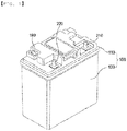
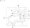
- FIG. 1 is a perspective view schematically showing a battery pack according to a first embodiment of the present invention
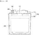
- FIG. 2 is a sectional view schematically showing the battery pack according to the first embodiment of the present invention.
- the battery pack according to the first embodiment of the present invention includes a casing 100 having an inner space, electrode terminals 210 and 220 exposed outside through through-holes (not shown) formed in the casing 100, and a battery module disposed in the casing 100, the battery module having a plurality of battery cells 300.
- the electrode terminals 210 and 220 may be configured so as to be exposed upwards in FIG. 1 .
- the casing 100 may have the shape of an approximately rectangular parallelepiped; however, the present invention is not limited as to the shape of the casing 100.
- the casing 100 serves to protect the battery cells 300 from external force.
- the casing 100 includes an upper housing 110 and a lower housing 120.
- the upper housing 110 and the lower housing 120 are coupled to each other such that the inner space, which is configured to receive the battery cells 300, is formed in the casing 100.
- Each of the upper housing 110 and the lower housing 120 may be made of plastic.
- the upper housing 110 and the lower housing 120 may be joined to each other by welding.
- the interior of the casing 100 may have a dustproof and waterproof structure.
- the present invention is not limited as to the material of each of the upper housing 110 and the lower housing 120.
- the upper housing 110 and the lower housing 120 may be coupled to each other by any of various fastening means, such as bolting and riveting, in place of welding.
- the plurality of battery cells 300 may be received in the lower housing 120.
- each of the battery cells 300 may be a pouch-shaped battery cell, and the pouch-shaped battery cell may include an electrode assembly configured by stacking a plurality of electrode plates in the state in which a separator is disposed therebetween and a pouch configured to wrap the electrode assembly.
- the lower housing 120 may have a battery cell receiving space having a width and a height corresponding respectively to the width and the length of each of the battery cells 300.
- a vent hole 190 configured to allow gas generated in the battery cells 300 to be discharged therethrough may be formed in the upper housing 110.
- the vent hole 190 has an inlet 191 configured to allow gas to be introduced therethrough and an outlet 192 configured to allow gas to be discharged therethrough. Consequently, gas generated in the battery cells 300 due to problems with the battery cells 300 may flow from the lower housing 120 to the upper housing 110, and may be discharged outside through the vent hole 190 of the upper housing 110 under a predetermined pressure.
- the upper housing 110 may have a gas capture space 160 configured to communicate with the vent hole 190.
- Gas generated in the battery cells 300 may be captured in the gas capture space 160.
- the pressure of the gas captured in the gas capture space 160 reaches the predetermined pressure, therefore, the gas may be discharged outside through the vent hole 190.
- the gas capture space 160 may be located at the middle of the upper part of the casing 100 or may be located at a position biased to one side from a vertical central axis of the casing 100. Consequently, the gas generated in the battery cells 300 may directly flow to the gas capture space 160 located at the middle of the upper part of the casing 100 (the middle of the upper housing 110). In addition, the gas that has flowed to the gas capture space 160 may directly flow toward the vent hole 190.
- the battery pack according to the first embodiment of the present invention may include a sound generator 400 configured to generate a sound such that, in the case in which gas is generated in the battery cells 300, a user can immediately confirm the same.
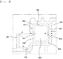
- FIG. 3 is a sectional view schematically showing the sound generator of the battery pack according to the first embodiment of the present invention and the flow of gas passing through the sound generator.
- the sound generator 400 may be mounted in the vent hole 190 of the casing 100 of the battery pack.
- the sound generator 400 may be configured as a single module, and may be inserted and fitted into the interior of the vent hole 190 of the casing 100.
- the sound generator 400 may have a size corresponding to the size of the inner space of the vent hole 190, and therefore the sound generator 400 may be fastened to the interior of the vent hole 190 in a tight fitting fashion, whereby fastening therebetween may be stably maintained.
- the sound generator 400 may be fitted into the interior of the vent hole 190, and then the sound generator 400 may be stably mounted in the vent hole 190 by welding, bolting, riveting, an adhesive, etc.
- the sound generator 400 Since the sound generator 400 is configured as a single separate module, the sound generator 400 may be fitted into a vent hole 190 of a battery pack having a conventional structure, and may be used in this state. Consequently, the sound generator 400 may be easily applied to a battery pack having a conventional structure. In this case, a space having a sufficient size to allow the sound generator 400 to pass toward the vent hole 190 may be secured at the outlet 192 side of the vent hole 190.
- the present invention is not limited to the construction in which the sound generator 400 is configured as a separate module.
- the sound generator 400 may be formed integrally with the casing 100.
- the sound generator 400 may be formed integrally with the casing 100 through injection molding, insert injection molding, etc.
- the sound generator 400 is installed in the vent hole 190 so as to block the vent hole 190, and is configured to allow gas to pass therethrough. In the process in which gas introduced through the inlet 191 of the vent hole 190 is discharged through the outlet 192 of the vent hole 190, therefore, the gas generates a sound when passing through the sound generator 400.
- the sound generator 400 may include a first portion 410 having a first orifice 411 formed at the inlet 191 side of the vent hole 190 and a second portion 420 disposed so as to be spaced apart from the first portion 410, a gas diffusion space 430 being formed between the first portion 410 and the second portion 420, the second portion 420 having a second orifice 421 formed at the outlet 192 side of the vent hole 190.
- the first portion 410 may have a plurality of first orifices 411.
- the plurality of first orifices 411 may be disposed about the center of the inlet 191 of the vent hole 190 at regular intervals in the circumferential direction thereof.
- the second portion 420 may have a plurality of second orifices 421.
- the plurality of second orifices 421 may be disposed about the center of the outlet 192 of the vent hole 190 at regular intervals in the circumferential direction thereof.
- the inner diameter of the first orifice 411 may be gradually increased from the inlet 191 of the vent hole 190 in a direction toward the gas diffusion space 430.
- the present invention is not limited to this construction, and the first orifice 411 may have a uniform inner diameter.
- the inner diameter of the second orifice 421 may be gradually increased from the gas diffusion space 430 in a direction toward the outlet 192 of the vent hole 190.
- the present invention is not limited to this construction, and the second orifice 421 may have a uniform inner diameter.
- gas introduced through the inlet 191 of the vent hole 190 pushes the first portion 410 of the sound generator 400, whereby pressure of the gas increases.
- the gas ejected into the gas diffusion space 430 generates a swirl while flowing very unstable.
- the gas ejected into the gas diffusion space 430 collides with the second portion 420. Consequently, a sound wave is generated due to the swirl of the gas and the collision of the gas with the second portion 420.
- some of the gas in the gas diffusion space 430 generates a swirl when passing through the second orifice 421 of the second portion 420 and being ejected outside, and a sound wave is generated due to this swirl.
- the sound wave generated by ejection of the gas as described above is transmitted to a user, whereby it is possible for the user to immediately confirm the situation in which the gas is ejected through the outlet 192 of the vent hole 190.
- a collision wall 180 installed so as to be spaced apart from the sound generator 400 and configured to allow the sound wave of the sound generated by the sound generator 400 to collide therewith may be provided at the outlet 192 side of the vent hole 190.
- the collision wall 180 may serve to reflect the sound wave toward a position at which the user is capable of clearly hearing the sound.
- the collision wall 180 may be formed in the upper housing 110 at a position adjacent to the outlet 192 side of the vent hole 190.
- the present invention is not limited to this construction, and the collision wall 180 may be formed integrally with the sound generator 400. Consequently, the sound generator 400 may be configured as a single module including the collision wall 180, and may be mounted in the vent hole 190.
- a concave portion 170 configured to reflect the sound wave of the sound generated by the sound generator 400 may be further provided at the outlet 192 side of the vent hole 190.
- the concave portion 170 may serve to reflect the sound wave toward a position at which the user is capable of clearly hearing the sound.
- the concave portion 170 may have a curved surface formed to induce smooth reflection of the sound wave discharged through the outlet 192 of the vent hole 190.
- the curved surface of the concave portion 170 may be curved toward the collision wall 180.
- the collision wall 180, the concave portion 170, the outlet 192 of the vent hole 190, and the second portion 420 of the sound generator 400 form a space having the shape of a predetermined bowl thereamong. This space may serve to reflect the sound wave toward a position at which the user is capable of clearly hearing the sound.
- the concave portion 170 may be formed in the upper housing 110 at a position adjacent to the outlet 192 side of the vent hole 190.
- the present invention is not limited to this construction, and the concave portion 170 may be formed integrally with the sound generator 400. Consequently, the sound generator 400 may be configured as a single module including the concave portion 170, and may be mounted in the vent hole 190.
- the battery pack according to the first embodiment of the present invention includes the sound generator 400, which is configured to generate a sound by the flow of gas generated in the battery cells 300. In the case in which gas is generated in the battery cells 300, therefore, it is possible for the user to immediately confirm the same.
- the sound generator 400 of the battery pack is configured to generate a sound only by the flow of gas. Consequently, it is possible for the user to confirm the generation of gas without additional electric power or power or without a separate sensor.
- FIG. 4 Components identical to the components of the first embodiment of the present invention are denoted by the same reference numerals, and a detailed description thereof will be omitted.
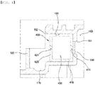
- FIG. 4 is a sectional view schematically showing a sound generator and a moisture blocking membrane of a battery pack according to a second embodiment of the present invention.
- the battery pack according to the second embodiment of the present invention may have a moisture blocking membrane 500 installed at an inlet 191 side of a vent hole 190 so as to block the inlet 191 and configured to allow the flow of gas into the vent hole 190 and to block the introduction of moisture into a casing.
- the moisture blocking membrane 500 is located between a gas capture space 160 and the vent hole 190 to partition the gas capture space 160 and the vent hole 190 from each other.
- the moisture blocking membrane 500 may be fixedly coupled to the inlet 191 of the vent hole 190 through various fastening means, such as welding, bolting, riveting, and an adhesive.
- the moisture blocking membrane 500 is configured to allow gas having a predetermined pressure to pass therethrough. When the pressure of gas captured in the gas capture space 160 reaches the predetermined pressure, therefore, the gas present in the gas capture space 160 may flow into the vent hole 190 through the moisture blocking membrane 500, and may generate a sound while passing through a sound generator 400.
- the moisture blocking membrane 500 is provided between the gas capture space 160 and the vent hole 190, whereby it is possible to prevent moisture from being introduced into the casing 100.
- the gas may be discharged outside through the vent hole 190 only when the pressure of the gas in the casing 100 reaches the predetermined pressure.
- FIG. 5 Components identical to the components of the first and second embodiments of the present invention are denoted by the same reference numerals, and a detailed description thereof will be omitted.
- FIG. 5 is a sectional view schematically showing a sound generator of a battery pack according to a third embodiment of the present invention and the flow of gas passing through the sound generator.
- the battery pack according to the third embodiment of the present invention may include a sound generator 600, and the sound generator 600 may include a partition wall 610 disposed at an inlet 191 side of a vent hole 190, the partition wall 610 having a gas passage hole 611 formed therein, and a vibration plate 620 supported by the partition wall 610, the vibration plate 620 being configured to be vibrated by the flow of gas that has passed through the gas passage hole 611 in order to generate a sound.
- the sound generator 600 may include a partition wall 610 disposed at an inlet 191 side of a vent hole 190, the partition wall 610 having a gas passage hole 611 formed therein, and a vibration plate 620 supported by the partition wall 610, the vibration plate 620 being configured to be vibrated by the flow of gas that has passed through the gas passage hole 611 in order to generate a sound.
- the sound generator 600 may be configured as a single module, and may be inserted and fitted into the interior of the vent hole 190, which is formed in a casing 100.
- the sound generator 600 may have a size corresponding to the size of an inner space of the vent hole 190, and therefore the sound generator 600 may be fastened to the interior of the vent hole 190 in a tight fitting fashion, whereby fastening therebetween may be stably maintained.
- the sound generator 600 may be fitted into the interior of the vent hole 190, and then the sound generator 600 may be stably mounted in the vent hole 190 by welding, bolting, riveting, an adhesive, etc.
- the sound generator 600 Since the sound generator 600 is configured as a single separate module, the sound generator 600 may be fitted into a vent hole 190 of a battery pack having a conventional structure, and may be used in this state. Consequently, the sound generator 600 may be easily applied to a battery pack having a conventional structure. In this case, a space having a sufficient size to allow the sound generator 600 to pass toward the vent hole 190 may be secured at an outlet 192 side of the vent hole 190.
- the present invention is not limited to the construction in which the sound generator 600 is configured as a separate module.
- the sound generator 600 may be formed integrally with the casing 100.
- the sound generator 600 may be formed integrally with the casing 100 through injection molding, insert injection molding, etc.
- the partition wall 610 may have a plurality of gas passage holes 611.
- the plurality of gas passage holes 611 may be disposed at regular intervals in the circumferential direction of the vibration plate 620.
- the vibration plate 620 may be made of plastic or metal that exhibits predetermined flexibility.
- the center of the vibration plate 620 may be fixed to the center of the partition wall 610 via a connection member having the shape of a predetermined bar.
- gas introduced through the inlet 191 of the vent hole 190 pushes the partition wall 610 of the sound generator 600, whereby pressure of the gas increases.
- some of the gas that pushes the partition wall 610 passes through the gas passage holes 611, and is then ejected toward the vibration plate 620.
- the vibration plate 620 may be vibrated by the ejected gas, and may vibrate ambient air to generate a sound wave.
- the sound generator 600 of the battery pack is configured to generate a sound only by the flow of gas. Consequently, it is possible for the user to confirm the generation of gas without additional electric power or power or without a separate sensor.
- the battery pack according to the embodiment of the present invention may be applied to a device including the battery pack as a power source.
- the device may be a computer, a cellular phone, a wearable electronic device, a power tool, an electric vehicle (EV), a hybrid electric vehicle, a plug-in hybrid electric vehicle, an electric two-wheeled vehicle, an electric golf cart, or an energy storage apparatus.
- the energy storage apparatus may be applied to various fields or places, such as a smart-grid system configured to control the supply and demand of electric power or a charging station for electric vehicles.
- a battery pack according to an embodiment of the present invention includes a sound generator configured to generate a sound by the flow of gas generated in a battery cell. In the case in which gas is generated in the battery cell, therefore, it is possible for a user to immediately confirm the same.
- the sound generator of the battery pack is configured to generate a sound only by the flow of gas. Consequently, it is possible for the user to confirm the generation of gas without additional electric power or power or without a separate sensor.
Landscapes
- Chemical & Material Sciences (AREA)
- Chemical Kinetics & Catalysis (AREA)
- Electrochemistry (AREA)
- General Chemical & Material Sciences (AREA)
- Engineering & Computer Science (AREA)
- Manufacturing & Machinery (AREA)
- Microelectronics & Electronic Packaging (AREA)
- Battery Mounting, Suspending (AREA)
- Gas Exhaust Devices For Batteries (AREA)
Abstract
Description
- The present invention relates to a battery pack.
- In recent years, with an increase in the demand for portable electronic devices, such as laptop computers, smartphones, and tablet computers, research has been actively conducted on high-performance secondary batteries that are capable of being repeatedly charged and discharged.
- In addition, secondary batteries have come to be widely used in medium- or large-sized devices, such as vehicles, robots, and satellites, as well as small-sized devices, such as portable electronic devices. In particular, as fossil fuels are being depleted and increasing attention is being paid to environmental pollution, research on hybrid vehicles and electric vehicles is being actively conducted. The most essential part of a hybrid vehicle or an electric vehicle is a battery pack configured to supply electric power to a motor. The battery pack includes a battery module including a plurality of battery cells, wherein the plurality of battery cells is connected to each other in series and/or in parallel, whereby the capacity and output of the battery module are increased.
- Basically, a battery cell is manufactured through a process of stacking a plurality of electrode plates in the state in which a separator is disposed therebetween and welding a plurality of electrode tabs to the plurality of electrode plates, respectively, to form an electrode assembly and wrapping the electrode assembly in an aluminum pouch so as to be sealed.
- During the use of the battery pack, gas may be generated in the battery cell. The gas may be generated due to the decomposition of an electrolyte when the lifespan of the battery cell expires, the battery cell is exposed to high temperature, the battery cell is overcharged, or short circuit occurs in the battery cell. The pouch of the battery cell generally has a gas discharge structure configured to prevent the occurrence of a safety-related accident due to the gas generated as described above.
- However, a conventional battery pack does not have a construction that is capable of immediately confirming the generation of gas in a battery cell. Therefore, there is a need for a construction capable of enabling a user to immediately confirm the generation of gas in the case in which the gas is generated in the battery cell such that the user can take a measure, such as exchange of the battery pack.
- The present invention has been made in view of the above problems, and it is an object of the present invention to provide a battery pack capable of enabling a user to immediately confirm the generation of gas in a battery cell.
- A battery pack according to an embodiment of the present invention provided to accomplish the above object may include a battery cell, a casing configured to receive the battery cell, the casing having formed therein a vent hole configured to allow gas generated in the battery cell to be discharged therethrough, and a sound generator installed in the vent hole so as to block the vent hole, the sound generator being configured to allow the gas to pass therethrough, the sound generator being configured to generate a sound by the flow of the gas when the gas is discharged from the casing through the vent hole.
- The sound generator may include a first portion having a first orifice formed at an inlet side of the vent hole and a second portion disposed so as to be spaced apart from the first portion, a gas diffusion space being formed between the first portion and the second portion, the second portion having a second orifice formed at an outlet side of the vent hole.
- The sound generator may include a partition wall disposed at the inlet side of the vent hole, the partition wall having a gas passage hole formed therein, and a vibration plate supported by the partition wall, the vibration plate being configured to be vibrated by the flow of gas that has passed through the gas passage hole in order to generate a sound.
- A collision wall installed so as to be spaced apart from the sound generator and configured to allow a sound wave of the sound generated by the sound generator to collide therewith may be provided at the outlet side of the vent hole.
- A concave portion configured to reflect a sound wave of the sound generated by the sound generator may be provided at the outlet side of the vent hole.
- A moisture blocking membrane may be installed at the inlet side of the vent hole so as to block the inlet, the moisture blocking membrane being configured to allow the flow of gas into the vent hole and to block the introduction of moisture into the casing.
- The casing may include an upper housing and a lower housing, the vent hole may be formed in the upper housing, and the battery cell may be received in the lower housing.
- The upper housing may have a gas capture space formed therein, the gas capture space being configured to communicate with the vent hole and to capture the gas.
- The following drawings appended to this specification are provided to illustrate preferred embodiments of the present invention and to aid in understanding the technical idea of the present invention together with the detailed description of the invention, a description of which will follow, and the present invention should not be interpreted as being limited only to matters described in the drawings.
-
FIG. 1 is a perspective view schematically showing a battery pack according to a first embodiment of the present invention. -
FIG. 2 is a sectional view schematically showing the battery pack according to the first embodiment of the present invention. -
FIG. 3 is a sectional view schematically showing a sound generator of the battery pack according to the first embodiment of the present invention and the flow of gas passing through the sound generator. -
FIG. 4 is a sectional view schematically showing a sound generator and a moisture blocking membrane of a battery pack according to a second embodiment of the present invention. -
FIG. 5 is a sectional view schematically showing a sound generator of a battery pack according to a third embodiment of the present invention and the flow of gas passing through the sound generator. - Embodiments of the present invention are provided in order to more completely describe the present invention to a person having ordinary skill in the art, and therefore the shape and size of each element in the drawings may be exaggerated, omitted, or schematically illustrated for clearer description. Consequently, the size or rate of each element does not entirely reflect the actual size or rate thereof.
- Hereinafter, the preferred embodiments of the present invention will be described in detail with reference to the accompanying drawings. It should be noted that terms or words used in this specification and the claims are not to be interpreted as having ordinary and dictionary-based meanings but as having meanings and concepts coinciding with the technical idea of the present invention based on the principle that the inventors may properly define the concepts of the terms in order to explain the invention in the best method.
-
FIG. 1 is a perspective view schematically showing a battery pack according to a first embodiment of the present invention, andFIG. 2 is a sectional view schematically showing the battery pack according to the first embodiment of the present invention. - As shown in
FIGS. 1 and2 , the battery pack according to the first embodiment of the present invention includes acasing 100 having an inner space,electrode terminals casing 100, and a battery module disposed in thecasing 100, the battery module having a plurality ofbattery cells 300. - As shown in
FIG. 1 , theelectrode terminals FIG. 1 . - As shown in
FIG. 1 , thecasing 100 may have the shape of an approximately rectangular parallelepiped; however, the present invention is not limited as to the shape of thecasing 100. Thecasing 100 serves to protect thebattery cells 300 from external force. Thecasing 100 includes anupper housing 110 and alower housing 120. Theupper housing 110 and thelower housing 120 are coupled to each other such that the inner space, which is configured to receive thebattery cells 300, is formed in thecasing 100. - Each of the
upper housing 110 and thelower housing 120 may be made of plastic. In this case, theupper housing 110 and thelower housing 120 may be joined to each other by welding. As a result, the interior of thecasing 100 may have a dustproof and waterproof structure. However, the present invention is not limited as to the material of each of theupper housing 110 and thelower housing 120. In addition, theupper housing 110 and thelower housing 120 may be coupled to each other by any of various fastening means, such as bolting and riveting, in place of welding. - The plurality of
battery cells 300 may be received in thelower housing 120. For example, each of thebattery cells 300 may be a pouch-shaped battery cell, and the pouch-shaped battery cell may include an electrode assembly configured by stacking a plurality of electrode plates in the state in which a separator is disposed therebetween and a pouch configured to wrap the electrode assembly. Thelower housing 120 may have a battery cell receiving space having a width and a height corresponding respectively to the width and the length of each of thebattery cells 300. - A
vent hole 190 configured to allow gas generated in thebattery cells 300 to be discharged therethrough may be formed in theupper housing 110. Thevent hole 190 has aninlet 191 configured to allow gas to be introduced therethrough and anoutlet 192 configured to allow gas to be discharged therethrough. Consequently, gas generated in thebattery cells 300 due to problems with thebattery cells 300 may flow from thelower housing 120 to theupper housing 110, and may be discharged outside through thevent hole 190 of theupper housing 110 under a predetermined pressure. - Meanwhile, the
upper housing 110 may have agas capture space 160 configured to communicate with thevent hole 190. Gas generated in thebattery cells 300 may be captured in thegas capture space 160. When the pressure of the gas captured in thegas capture space 160 reaches the predetermined pressure, therefore, the gas may be discharged outside through thevent hole 190. - As an example, the
gas capture space 160 may be located at the middle of the upper part of thecasing 100 or may be located at a position biased to one side from a vertical central axis of thecasing 100. Consequently, the gas generated in thebattery cells 300 may directly flow to thegas capture space 160 located at the middle of the upper part of the casing 100 (the middle of the upper housing 110). In addition, the gas that has flowed to thegas capture space 160 may directly flow toward thevent hole 190. - The battery pack according to the first embodiment of the present invention may include a
sound generator 400 configured to generate a sound such that, in the case in which gas is generated in thebattery cells 300, a user can immediately confirm the same. - Hereinafter, the
sound generator 400 of the battery pack according to the first embodiment of the present invention will be described with reference toFIG. 3. FIG. 3 is a sectional view schematically showing the sound generator of the battery pack according to the first embodiment of the present invention and the flow of gas passing through the sound generator. - As shown in
FIG. 3 , thesound generator 400 may be mounted in thevent hole 190 of thecasing 100 of the battery pack. - As an example, the
sound generator 400 may be configured as a single module, and may be inserted and fitted into the interior of thevent hole 190 of thecasing 100. Thesound generator 400 may have a size corresponding to the size of the inner space of thevent hole 190, and therefore thesound generator 400 may be fastened to the interior of thevent hole 190 in a tight fitting fashion, whereby fastening therebetween may be stably maintained. - Alternatively, the
sound generator 400 may be fitted into the interior of thevent hole 190, and then thesound generator 400 may be stably mounted in thevent hole 190 by welding, bolting, riveting, an adhesive, etc. - Since the
sound generator 400 is configured as a single separate module, thesound generator 400 may be fitted into avent hole 190 of a battery pack having a conventional structure, and may be used in this state. Consequently, thesound generator 400 may be easily applied to a battery pack having a conventional structure. In this case, a space having a sufficient size to allow thesound generator 400 to pass toward thevent hole 190 may be secured at theoutlet 192 side of thevent hole 190. - However, the present invention is not limited to the construction in which the
sound generator 400 is configured as a separate module. As another example, thesound generator 400 may be formed integrally with thecasing 100. For example, thesound generator 400 may be formed integrally with thecasing 100 through injection molding, insert injection molding, etc. - The
sound generator 400 is installed in thevent hole 190 so as to block thevent hole 190, and is configured to allow gas to pass therethrough. In the process in which gas introduced through theinlet 191 of thevent hole 190 is discharged through theoutlet 192 of thevent hole 190, therefore, the gas generates a sound when passing through thesound generator 400. - The
sound generator 400 may include afirst portion 410 having afirst orifice 411 formed at theinlet 191 side of thevent hole 190 and asecond portion 420 disposed so as to be spaced apart from thefirst portion 410, agas diffusion space 430 being formed between thefirst portion 410 and thesecond portion 420, thesecond portion 420 having asecond orifice 421 formed at theoutlet 192 side of thevent hole 190. - Depending on circumstances, the
first portion 410 may have a plurality offirst orifices 411. The plurality offirst orifices 411 may be disposed about the center of theinlet 191 of thevent hole 190 at regular intervals in the circumferential direction thereof. In the same manner, thesecond portion 420 may have a plurality ofsecond orifices 421. The plurality ofsecond orifices 421 may be disposed about the center of theoutlet 192 of thevent hole 190 at regular intervals in the circumferential direction thereof. - In order to effectively generate a swirl of gas, the inner diameter of the
first orifice 411 may be gradually increased from theinlet 191 of thevent hole 190 in a direction toward thegas diffusion space 430. However, the present invention is not limited to this construction, and thefirst orifice 411 may have a uniform inner diameter. In the same manner, in order to effectively generate a swirl of gas, the inner diameter of thesecond orifice 421 may be gradually increased from thegas diffusion space 430 in a direction toward theoutlet 192 of thevent hole 190. However, the present invention is not limited to this construction, and thesecond orifice 421 may have a uniform inner diameter. - According to this construction, gas introduced through the
inlet 191 of thevent hole 190 pushes thefirst portion 410 of thesound generator 400, whereby pressure of the gas increases. - When the pressure of the gas introduced through the
inlet 191 of thevent hole 190 reaches a predetermined pressure, some of the gas that pushes thefirst portion 410 passes through thefirst orifice 411 and is then ejected into thegas diffusion space 430. - At this time, the gas ejected into the
gas diffusion space 430 generates a swirl while flowing very unstable. In addition, the gas ejected into thegas diffusion space 430 collides with thesecond portion 420. Consequently, a sound wave is generated due to the swirl of the gas and the collision of the gas with thesecond portion 420. - In addition, some of the gas in the
gas diffusion space 430 generates a swirl when passing through thesecond orifice 421 of thesecond portion 420 and being ejected outside, and a sound wave is generated due to this swirl. - The sound wave generated by ejection of the gas as described above is transmitted to a user, whereby it is possible for the user to immediately confirm the situation in which the gas is ejected through the
outlet 192 of thevent hole 190. - Meanwhile, a
collision wall 180 installed so as to be spaced apart from thesound generator 400 and configured to allow the sound wave of the sound generated by thesound generator 400 to collide therewith may be provided at theoutlet 192 side of thevent hole 190. Thecollision wall 180 may serve to reflect the sound wave toward a position at which the user is capable of clearly hearing the sound. - The
collision wall 180 may be formed in theupper housing 110 at a position adjacent to theoutlet 192 side of thevent hole 190. However, the present invention is not limited to this construction, and thecollision wall 180 may be formed integrally with thesound generator 400. Consequently, thesound generator 400 may be configured as a single module including thecollision wall 180, and may be mounted in thevent hole 190. - In addition, a
concave portion 170 configured to reflect the sound wave of the sound generated by thesound generator 400 may be further provided at theoutlet 192 side of thevent hole 190. In the same manner as thecollision wall 180, theconcave portion 170 may serve to reflect the sound wave toward a position at which the user is capable of clearly hearing the sound. - The
concave portion 170 may have a curved surface formed to induce smooth reflection of the sound wave discharged through theoutlet 192 of thevent hole 190. In addition, the curved surface of theconcave portion 170 may be curved toward thecollision wall 180. Meanwhile, thecollision wall 180, theconcave portion 170, theoutlet 192 of thevent hole 190, and thesecond portion 420 of thesound generator 400 form a space having the shape of a predetermined bowl thereamong. This space may serve to reflect the sound wave toward a position at which the user is capable of clearly hearing the sound. - The
concave portion 170 may be formed in theupper housing 110 at a position adjacent to theoutlet 192 side of thevent hole 190. However, the present invention is not limited to this construction, and theconcave portion 170 may be formed integrally with thesound generator 400. Consequently, thesound generator 400 may be configured as a single module including theconcave portion 170, and may be mounted in thevent hole 190. - The battery pack according to the first embodiment of the present invention includes the
sound generator 400, which is configured to generate a sound by the flow of gas generated in thebattery cells 300. In the case in which gas is generated in thebattery cells 300, therefore, it is possible for the user to immediately confirm the same. - In addition, according to the first embodiment of the present invention, the
sound generator 400 of the battery pack is configured to generate a sound only by the flow of gas. Consequently, it is possible for the user to confirm the generation of gas without additional electric power or power or without a separate sensor. - Hereinafter, a battery pack according to a second embodiment of the present invention will be described with reference to
FIG. 4 . Components identical to the components of the first embodiment of the present invention are denoted by the same reference numerals, and a detailed description thereof will be omitted. -
FIG. 4 is a sectional view schematically showing a sound generator and a moisture blocking membrane of a battery pack according to a second embodiment of the present invention. - As shown in
FIG. 4 , the battery pack according to the second embodiment of the present invention may have amoisture blocking membrane 500 installed at aninlet 191 side of avent hole 190 so as to block theinlet 191 and configured to allow the flow of gas into thevent hole 190 and to block the introduction of moisture into a casing. - The
moisture blocking membrane 500 is located between agas capture space 160 and thevent hole 190 to partition thegas capture space 160 and thevent hole 190 from each other. Themoisture blocking membrane 500 may be fixedly coupled to theinlet 191 of thevent hole 190 through various fastening means, such as welding, bolting, riveting, and an adhesive. - The
moisture blocking membrane 500 is configured to allow gas having a predetermined pressure to pass therethrough. When the pressure of gas captured in thegas capture space 160 reaches the predetermined pressure, therefore, the gas present in thegas capture space 160 may flow into thevent hole 190 through themoisture blocking membrane 500, and may generate a sound while passing through asound generator 400. - In the battery pack according to the second embodiment of the present invention, the
moisture blocking membrane 500 is provided between thegas capture space 160 and thevent hole 190, whereby it is possible to prevent moisture from being introduced into thecasing 100. In addition, the gas may be discharged outside through thevent hole 190 only when the pressure of the gas in thecasing 100 reaches the predetermined pressure. - Hereinafter, a battery pack according to a third embodiment of the present invention will be described with reference to
FIG. 5 . Components identical to the components of the first and second embodiments of the present invention are denoted by the same reference numerals, and a detailed description thereof will be omitted. -
FIG. 5 is a sectional view schematically showing a sound generator of a battery pack according to a third embodiment of the present invention and the flow of gas passing through the sound generator. - As shown in
FIG. 5 , the battery pack according to the third embodiment of the present invention may include asound generator 600, and thesound generator 600 may include apartition wall 610 disposed at aninlet 191 side of avent hole 190, thepartition wall 610 having agas passage hole 611 formed therein, and avibration plate 620 supported by thepartition wall 610, thevibration plate 620 being configured to be vibrated by the flow of gas that has passed through thegas passage hole 611 in order to generate a sound. - As an example, the
sound generator 600 may be configured as a single module, and may be inserted and fitted into the interior of thevent hole 190, which is formed in acasing 100. Thesound generator 600 may have a size corresponding to the size of an inner space of thevent hole 190, and therefore thesound generator 600 may be fastened to the interior of thevent hole 190 in a tight fitting fashion, whereby fastening therebetween may be stably maintained. - Alternatively, the
sound generator 600 may be fitted into the interior of thevent hole 190, and then thesound generator 600 may be stably mounted in thevent hole 190 by welding, bolting, riveting, an adhesive, etc. - Since the
sound generator 600 is configured as a single separate module, thesound generator 600 may be fitted into avent hole 190 of a battery pack having a conventional structure, and may be used in this state. Consequently, thesound generator 600 may be easily applied to a battery pack having a conventional structure. In this case, a space having a sufficient size to allow thesound generator 600 to pass toward thevent hole 190 may be secured at anoutlet 192 side of thevent hole 190. - However, the present invention is not limited to the construction in which the
sound generator 600 is configured as a separate module. As another example, thesound generator 600 may be formed integrally with thecasing 100. For example, thesound generator 600 may be formed integrally with thecasing 100 through injection molding, insert injection molding, etc. - The
partition wall 610 may have a plurality of gas passage holes 611. The plurality of gas passage holes 611 may be disposed at regular intervals in the circumferential direction of thevibration plate 620. - The
vibration plate 620 may be made of plastic or metal that exhibits predetermined flexibility. The center of thevibration plate 620 may be fixed to the center of thepartition wall 610 via a connection member having the shape of a predetermined bar. - According to this construction, gas introduced through the
inlet 191 of thevent hole 190 pushes thepartition wall 610 of thesound generator 600, whereby pressure of the gas increases. At this time, some of the gas that pushes thepartition wall 610 passes through the gas passage holes 611, and is then ejected toward thevibration plate 620. As a result, thevibration plate 620 may be vibrated by the ejected gas, and may vibrate ambient air to generate a sound wave. - According to the third embodiment of the present invention, the
sound generator 600 of the battery pack is configured to generate a sound only by the flow of gas. Consequently, it is possible for the user to confirm the generation of gas without additional electric power or power or without a separate sensor. - The battery pack according to the embodiment of the present invention may be applied to a device including the battery pack as a power source.
- For example, the device may be a computer, a cellular phone, a wearable electronic device, a power tool, an electric vehicle (EV), a hybrid electric vehicle, a plug-in hybrid electric vehicle, an electric two-wheeled vehicle, an electric golf cart, or an energy storage apparatus. The energy storage apparatus may be applied to various fields or places, such as a smart-grid system configured to control the supply and demand of electric power or a charging station for electric vehicles.
- The preferred embodiments of the present invention have been described illustratively; however, the scope of the present invention is not limited to such specific embodiments, and may be appropriately changed within the category described in the claims.
-
- 100: Casing
- 300: Battery cells
- 400: Sound generator
- 500: Moisture blocking membrane
- 600: Sound generator
- A battery pack according to an embodiment of the present invention includes a sound generator configured to generate a sound by the flow of gas generated in a battery cell. In the case in which gas is generated in the battery cell, therefore, it is possible for a user to immediately confirm the same.
- According to the embodiment of the present invention, the sound generator of the battery pack is configured to generate a sound only by the flow of gas. Consequently, it is possible for the user to confirm the generation of gas without additional electric power or power or without a separate sensor.
Claims (10)
- A battery pack comprising:a battery cell;a casing configured to receive the battery cell, the casing having formed therein a vent hole configured to allow gas generated in the battery cell to be discharged therethrough; anda sound generator installed in the vent hole so as to block the vent hole, the sound generator being configured to allow the gas to pass therethrough, the sound generator being configured to generate a sound by flow of the gas when the gas is discharged from the casing through the vent hole.
- The battery pack according to claim 1, wherein the sound generator comprises:a first portion having a first orifice formed at an inlet side of the vent hole; anda second portion disposed so as to be spaced apart from the first portion, a gas diffusion space being formed between the first portion and the second portion, the second portion having a second orifice formed at an outlet side of the vent hole.
- The battery pack according to claim 1, wherein the sound generator comprises:a partition wall disposed at an inlet side of the vent hole, the partition wall having a gas passage hole formed therein; anda vibration plate supported by the partition wall, the vibration plate being configured to be vibrated by flow of gas that has passed through the gas passage hole in order to generate a sound.
- The battery pack according to claim 1, wherein a collision wall installed so as to be spaced apart from the sound generator and configured to allow a sound wave of the sound generated by the sound generator to collide therewith is provided at an outlet side of the vent hole.
- The battery pack according to claim 1, wherein a concave portion configured to reflect a sound wave of the sound generated by the sound generator is provided at an outlet side of the vent hole.
- The battery pack according to claim 1, wherein a moisture blocking membrane is installed at an inlet side of the vent hole so as to block the inlet, the moisture blocking membrane being configured to allow flow of gas into the vent hole and to block introduction of moisture into the casing.
- The battery pack according to claim 1, wherein the casing comprises an upper housing and a lower housing, the vent hole is formed in the upper housing, and the battery cell is received in the lower housing.
- The battery pack according to claim 7, wherein the upper housing has a gas capture space formed therein, the gas capture space being configured to communicate with the vent hole and to capture the gas.
- A device having the battery pack according to any one of claims 1 to 8.
- The device according to claim 9, wherein the device is one of a computer, a cellular phone, a wearable electronic device, a power tool, an electric vehicle (EV), a hybrid electric vehicle, a plug-in hybrid electric vehicle, an electric two-wheeled vehicle, an electric golf cart, and an energy storage apparatus.
Applications Claiming Priority (2)
| Application Number | Priority Date | Filing Date | Title |
|---|---|---|---|
| KR1020180144863A KR102448322B1 (en) | 2018-11-21 | 2018-11-21 | battery pack |
| PCT/KR2019/015855 WO2020106021A1 (en) | 2018-11-21 | 2019-11-19 | Battery pack |
Publications (3)
| Publication Number | Publication Date |
|---|---|
| EP3758095A1 true EP3758095A1 (en) | 2020-12-30 |
| EP3758095A4 EP3758095A4 (en) | 2021-05-26 |
| EP3758095B1 EP3758095B1 (en) | 2025-10-22 |
Family
ID=70774727
Family Applications (1)
| Application Number | Title | Priority Date | Filing Date |
|---|---|---|---|
| EP19888162.5A Active EP3758095B1 (en) | 2018-11-21 | 2019-11-19 | Battery pack |
Country Status (8)
| Country | Link |
|---|---|
| US (2) | US11502368B2 (en) |
| EP (1) | EP3758095B1 (en) |
| JP (1) | JP7102023B2 (en) |
| KR (1) | KR102448322B1 (en) |
| CN (1) | CN111868961B (en) |
| ES (1) | ES3052732T3 (en) |
| PL (1) | PL3758095T3 (en) |
| WO (1) | WO2020106021A1 (en) |
Families Citing this family (3)
| Publication number | Priority date | Publication date | Assignee | Title |
|---|---|---|---|---|
| KR102935497B1 (en) * | 2021-07-14 | 2026-03-06 | 주식회사 엘지에너지솔루션 | Venting device including sealing cap and battery module including same |
| KR102580196B1 (en) * | 2021-07-26 | 2023-09-20 | 한국앤컴퍼니 주식회사 | Thermal runaway detection device that can be applied to VRLA batteries for UPS |
| DE102023001932B3 (en) | 2023-05-12 | 2024-07-18 | Mercedes-Benz Group AG | Warning device for a battery, battery unit and vehicle |
Family Cites Families (21)
| Publication number | Priority date | Publication date | Assignee | Title |
|---|---|---|---|---|
| US2143340A (en) * | 1937-03-11 | 1939-01-10 | Elton L Willits | Gas operated signal for secondary batteries |
| US2288984A (en) * | 1939-08-12 | 1942-07-07 | Edw K Tryon Company | Battery alarm |
| US5329872A (en) | 1991-08-30 | 1994-07-19 | Wright Howard W | All weather safety whistle and sound generator |
| JP4172670B2 (en) * | 1999-06-15 | 2008-10-29 | シチズン電子株式会社 | Buzzer with battery compartment |
| JP2009043592A (en) | 2007-08-09 | 2009-02-26 | Toshiba Corp | Battery module |
| KR20110012622A (en) * | 2009-07-31 | 2011-02-09 | 세종대학교산학협력단 | Method and apparatus for providing exhibition viewing service based on user's emotional information in ubiquitous computing space |
| KR20110126222A (en) * | 2010-05-17 | 2011-11-23 | 양기와 | Explosion-Free Butane Gas Burner |
| US20120263982A1 (en) * | 2010-11-30 | 2012-10-18 | Shunsuke Yasui | Battery pack |
| US8925478B2 (en) * | 2012-05-01 | 2015-01-06 | Curtis E. Graber | Directional isophasic toroidal whistle |
| KR101388621B1 (en) * | 2012-12-20 | 2014-04-24 | 현대오트론 주식회사 | Battery pack unit |
| JP2014192092A (en) | 2013-03-28 | 2014-10-06 | Sanyo Electric Co Ltd | Battery module |
| JP6225499B2 (en) * | 2013-05-28 | 2017-11-08 | 睦月電機株式会社 | Explosion-proof device for sealed electrochemical devices |
| JP2016025073A (en) | 2014-07-25 | 2016-02-08 | 株式会社豊田自動織機 | Battery module and battery pack including the same |
| CN104505482A (en) * | 2014-11-25 | 2015-04-08 | 广安鼎恒新能源锂电池制造股份有限公司 | New lithium ion battery with protection function and preparation process thereof |
| KR20160109513A (en) * | 2015-03-11 | 2016-09-21 | 삼성에스디아이 주식회사 | Battery pack |
| KR20160113888A (en) | 2015-03-23 | 2016-10-04 | 삼성에스디아이 주식회사 | Battery pack |
| KR102358433B1 (en) | 2015-04-17 | 2022-02-04 | 삼성에스디아이 주식회사 | Battery pack |
| CN208173340U (en) | 2015-10-30 | 2018-11-30 | 株式会社村田制作所 | LC composite device and processor |
| KR20170051067A (en) * | 2015-11-02 | 2017-05-11 | 주식회사 아트라스비엑스 | A gas alarm for battery |
| KR101794850B1 (en) | 2016-06-17 | 2017-11-08 | 현대자동차주식회사 | Exhaust sound pipe using exhaust gas flow as exciting force |
| DE102018211162A1 (en) * | 2018-07-06 | 2020-01-09 | Bayerische Motoren Werke Aktiengesellschaft | Vehicle with a high-voltage battery and method for generating an acoustic warning signal |
-
2018
- 2018-11-21 KR KR1020180144863A patent/KR102448322B1/en active Active
-
2019
- 2019-11-19 WO PCT/KR2019/015855 patent/WO2020106021A1/en not_active Ceased
- 2019-11-19 US US17/040,183 patent/US11502368B2/en active Active
- 2019-11-19 JP JP2020548923A patent/JP7102023B2/en active Active
- 2019-11-19 PL PL19888162.5T patent/PL3758095T3/en unknown
- 2019-11-19 CN CN201980018115.4A patent/CN111868961B/en active Active
- 2019-11-19 ES ES19888162T patent/ES3052732T3/en active Active
- 2019-11-19 EP EP19888162.5A patent/EP3758095B1/en active Active
-
2022
- 2022-09-28 US US17/954,700 patent/US11652258B2/en active Active
Also Published As
| Publication number | Publication date |
|---|---|
| WO2020106021A1 (en) | 2020-05-28 |
| EP3758095A4 (en) | 2021-05-26 |
| US20230088261A1 (en) | 2023-03-23 |
| ES3052732T3 (en) | 2026-01-13 |
| US20210013472A1 (en) | 2021-01-14 |
| PL3758095T3 (en) | 2026-02-16 |
| KR102448322B1 (en) | 2022-09-29 |
| CN111868961B (en) | 2022-11-25 |
| CN111868961A (en) | 2020-10-30 |
| EP3758095B1 (en) | 2025-10-22 |
| JP2021516435A (en) | 2021-07-01 |
| KR20200059753A (en) | 2020-05-29 |
| US11502368B2 (en) | 2022-11-15 |
| JP7102023B2 (en) | 2022-07-19 |
| US11652258B2 (en) | 2023-05-16 |
Similar Documents
| Publication | Publication Date | Title |
|---|---|---|
| US11652258B2 (en) | Battery pack | |
| US11784360B2 (en) | Battery module | |
| JP6578435B2 (en) | Battery module and battery pack including the same | |
| EP2991131B1 (en) | Battery module assembly | |
| EP2450981B1 (en) | Secondary battery module | |
| US11588193B2 (en) | Battery module | |
| US20180229621A1 (en) | Battery module, battery pack comprising battery module, and vehicle comprising battery pack | |
| AU2018308076B2 (en) | Battery module, and battery pack and energy storage system including the same | |
| CN100588003C (en) | Secondary battery module | |
| KR20150062743A (en) | Battery module and battery pack including the same | |
| EP4002570A1 (en) | Battery module and battery pack comprising same | |
| JPWO2015019559A1 (en) | Battery unit | |
| EP3522254A1 (en) | Battery module, battery pack including battery module, and vehicle including battery pack | |
| KR20160054269A (en) | Battery module and battery pack including the same | |
| EP4210154A1 (en) | Battery pack and device comprising same | |
| US12456779B2 (en) | Battery module, battery pack, and vehicle | |
| CN115917834B (en) | Battery module, battery pack including the battery module, and electric vehicle | |
| CN115699409B (en) | Battery packs and vehicles | |
| EP3608993B1 (en) | Battery module comprising connecting board | |
| CN118743076A (en) | Battery Pack | |
| KR20160144764A (en) | Battery Pack | |
| KR20200055336A (en) | Battery pack | |
| KR20190036255A (en) | Battery module, battery pack and vehicle comprising the same | |
| EP4683082A1 (en) | Battery pack and device including same | |
| CN121909559A (en) | Battery pack |
Legal Events
| Date | Code | Title | Description |
|---|---|---|---|
| STAA | Information on the status of an ep patent application or granted ep patent |
Free format text: STATUS: THE INTERNATIONAL PUBLICATION HAS BEEN MADE |
|
| PUAI | Public reference made under article 153(3) epc to a published international application that has entered the european phase |
Free format text: ORIGINAL CODE: 0009012 |
|
| STAA | Information on the status of an ep patent application or granted ep patent |
Free format text: STATUS: REQUEST FOR EXAMINATION WAS MADE |
|
| 17P | Request for examination filed |
Effective date: 20200925 |
|
| AK | Designated contracting states |
Kind code of ref document: A1 Designated state(s): AL AT BE BG CH CY CZ DE DK EE ES FI FR GB GR HR HU IE IS IT LI LT LU LV MC MK MT NL NO PL PT RO RS SE SI SK SM TR |
|
| AX | Request for extension of the european patent |
Extension state: BA ME |
|
| REG | Reference to a national code |
Ref country code: DE Ref legal event code: R079 Free format text: PREVIOUS MAIN CLASS: H01M0002120000 Ipc: H01M0010480000 Ref country code: DE Ref legal event code: R079 Ref document number: 602019077262 Country of ref document: DE Free format text: PREVIOUS MAIN CLASS: H01M0002120000 Ipc: H01M0010480000 |
|
| A4 | Supplementary search report drawn up and despatched |
Effective date: 20210428 |
|
| RIC1 | Information provided on ipc code assigned before grant |
Ipc: H01M 10/48 20060101AFI20210421BHEP Ipc: H01M 50/358 20210101ALI20210421BHEP |
|
| RAP1 | Party data changed (applicant data changed or rights of an application transferred) |
Owner name: LG ENERGY SOLUTION LTD. |
|
| DAV | Request for validation of the european patent (deleted) | ||
| DAX | Request for extension of the european patent (deleted) | ||
| RAP3 | Party data changed (applicant data changed or rights of an application transferred) |
Owner name: LG ENERGY SOLUTION, LTD. |
|
| STAA | Information on the status of an ep patent application or granted ep patent |
Free format text: STATUS: EXAMINATION IS IN PROGRESS |
|
| 17Q | First examination report despatched |
Effective date: 20221220 |
|
| GRAP | Despatch of communication of intention to grant a patent |
Free format text: ORIGINAL CODE: EPIDOSNIGR1 |
|
| STAA | Information on the status of an ep patent application or granted ep patent |
Free format text: STATUS: GRANT OF PATENT IS INTENDED |
|
| INTG | Intention to grant announced |
Effective date: 20250612 |
|
| P01 | Opt-out of the competence of the unified patent court (upc) registered |
Free format text: CASE NUMBER: APP_31531/2025 Effective date: 20250701 |
|
| GRAS | Grant fee paid |
Free format text: ORIGINAL CODE: EPIDOSNIGR3 |
|
| GRAA | (expected) grant |
Free format text: ORIGINAL CODE: 0009210 |
|
| STAA | Information on the status of an ep patent application or granted ep patent |
Free format text: STATUS: THE PATENT HAS BEEN GRANTED |
|
| AK | Designated contracting states |
Kind code of ref document: B1 Designated state(s): AL AT BE BG CH CY CZ DE DK EE ES FI FR GB GR HR HU IE IS IT LI LT LU LV MC MK MT NL NO PL PT RO RS SE SI SK SM TR |
|
| REG | Reference to a national code |
Ref country code: CH Ref legal event code: F10 Free format text: ST27 STATUS EVENT CODE: U-0-0-F10-F00 (AS PROVIDED BY THE NATIONAL OFFICE) Effective date: 20251022 Ref country code: GB Ref legal event code: FG4D |
|
| REG | Reference to a national code |
Ref country code: DE Ref legal event code: R096 Ref document number: 602019077262 Country of ref document: DE |
|
| REG | Reference to a national code |
Ref country code: IE Ref legal event code: FG4D |
|
| REG | Reference to a national code |
Ref country code: SE Ref legal event code: TRGR |
|
| PGFP | Annual fee paid to national office [announced via postgrant information from national office to epo] |
Ref country code: DE Payment date: 20251208 Year of fee payment: 7 |
|
| PGFP | Annual fee paid to national office [announced via postgrant information from national office to epo] |
Ref country code: GB Payment date: 20251208 Year of fee payment: 7 |
|
| REG | Reference to a national code |
Ref country code: ES Ref legal event code: FG2A Ref document number: 3052732 Country of ref document: ES Kind code of ref document: T3 Effective date: 20260113 |
|
| PGFP | Annual fee paid to national office [announced via postgrant information from national office to epo] |
Ref country code: HU Payment date: 20251216 Year of fee payment: 7 Ref country code: FR Payment date: 20251209 Year of fee payment: 7 |
|
| PGFP | Annual fee paid to national office [announced via postgrant information from national office to epo] |
Ref country code: BE Payment date: 20251209 Year of fee payment: 7 |
|
| PGFP | Annual fee paid to national office [announced via postgrant information from national office to epo] |
Ref country code: SE Payment date: 20251209 Year of fee payment: 7 |
|
| PGFP | Annual fee paid to national office [announced via postgrant information from national office to epo] |
Ref country code: ES Payment date: 20251215 Year of fee payment: 7 |
|
| REG | Reference to a national code |
Ref country code: NL Ref legal event code: MP Effective date: 20251022 |
|
| PG25 | Lapsed in a contracting state [announced via postgrant information from national office to epo] |
Ref country code: NL Free format text: LAPSE BECAUSE OF FAILURE TO SUBMIT A TRANSLATION OF THE DESCRIPTION OR TO PAY THE FEE WITHIN THE PRESCRIBED TIME-LIMIT Effective date: 20251022 |
|
| REG | Reference to a national code |
Ref country code: LT Ref legal event code: MG9D |
|
| PG25 | Lapsed in a contracting state [announced via postgrant information from national office to epo] |
Ref country code: NO Free format text: LAPSE BECAUSE OF FAILURE TO SUBMIT A TRANSLATION OF THE DESCRIPTION OR TO PAY THE FEE WITHIN THE PRESCRIBED TIME-LIMIT Effective date: 20260122 |
|
| PG25 | Lapsed in a contracting state [announced via postgrant information from national office to epo] |
Ref country code: AT Free format text: LAPSE BECAUSE OF FAILURE TO SUBMIT A TRANSLATION OF THE DESCRIPTION OR TO PAY THE FEE WITHIN THE PRESCRIBED TIME-LIMIT Effective date: 20251022 Ref country code: FI Free format text: LAPSE BECAUSE OF FAILURE TO SUBMIT A TRANSLATION OF THE DESCRIPTION OR TO PAY THE FEE WITHIN THE PRESCRIBED TIME-LIMIT Effective date: 20251022 Ref country code: HR Free format text: LAPSE BECAUSE OF FAILURE TO SUBMIT A TRANSLATION OF THE DESCRIPTION OR TO PAY THE FEE WITHIN THE PRESCRIBED TIME-LIMIT Effective date: 20251022 |
|
| REG | Reference to a national code |
Ref country code: AT Ref legal event code: MK05 Ref document number: 1850022 Country of ref document: AT Kind code of ref document: T Effective date: 20251022 |
|
| PG25 | Lapsed in a contracting state [announced via postgrant information from national office to epo] |
Ref country code: RS Free format text: LAPSE BECAUSE OF FAILURE TO SUBMIT A TRANSLATION OF THE DESCRIPTION OR TO PAY THE FEE WITHIN THE PRESCRIBED TIME-LIMIT Effective date: 20260122 |
|
| PG25 | Lapsed in a contracting state [announced via postgrant information from national office to epo] |
Ref country code: IS Free format text: LAPSE BECAUSE OF FAILURE TO SUBMIT A TRANSLATION OF THE DESCRIPTION OR TO PAY THE FEE WITHIN THE PRESCRIBED TIME-LIMIT Effective date: 20260222 |