EP3758094B1 - Battery pack and battery pack assembly apparatus - Google Patents
Battery pack and battery pack assembly apparatus Download PDFInfo
- Publication number
- EP3758094B1 EP3758094B1 EP20735998.5A EP20735998A EP3758094B1 EP 3758094 B1 EP3758094 B1 EP 3758094B1 EP 20735998 A EP20735998 A EP 20735998A EP 3758094 B1 EP3758094 B1 EP 3758094B1
- Authority
- EP
- European Patent Office
- Prior art keywords
- housing
- support
- contact surface
- battery pack
- pressing module
- Prior art date
- Legal status (The legal status is an assumption and is not a legal conclusion. Google has not performed a legal analysis and makes no representation as to the accuracy of the status listed.)
- Active
Links
Images



Classifications
-
- B—PERFORMING OPERATIONS; TRANSPORTING
- B23—MACHINE TOOLS; METAL-WORKING NOT OTHERWISE PROVIDED FOR
- B23K—SOLDERING OR UNSOLDERING; WELDING; CLADDING OR PLATING BY SOLDERING OR WELDING; CUTTING BY APPLYING HEAT LOCALLY, e.g. FLAME CUTTING; WORKING BY LASER BEAM
- B23K37/00—Auxiliary devices or processes, not specially adapted for a procedure covered by only one of the other main groups of this subclass
- B23K37/04—Auxiliary devices or processes, not specially adapted for a procedure covered by only one of the other main groups of this subclass for holding or positioning work
-
- H—ELECTRICITY
- H01—ELECTRIC ELEMENTS
- H01M—PROCESSES OR MEANS, e.g. BATTERIES, FOR THE DIRECT CONVERSION OF CHEMICAL ENERGY INTO ELECTRICAL ENERGY
- H01M10/00—Secondary cells; Manufacture thereof
- H01M10/04—Construction or manufacture in general
- H01M10/0404—Machines for assembling batteries
-
- H—ELECTRICITY
- H01—ELECTRIC ELEMENTS
- H01M—PROCESSES OR MEANS, e.g. BATTERIES, FOR THE DIRECT CONVERSION OF CHEMICAL ENERGY INTO ELECTRICAL ENERGY
- H01M50/00—Constructional details or processes of manufacture of the non-active parts of electrochemical cells other than fuel cells, e.g. hybrid cells
- H01M50/20—Mountings; Secondary casings or frames; Racks, modules or packs; Suspension devices; Shock absorbers; Transport or carrying devices; Holders
- H01M50/202—Casings or frames around the primary casing of a single cell or a single battery
-
- H—ELECTRICITY
- H01—ELECTRIC ELEMENTS
- H01M—PROCESSES OR MEANS, e.g. BATTERIES, FOR THE DIRECT CONVERSION OF CHEMICAL ENERGY INTO ELECTRICAL ENERGY
- H01M50/00—Constructional details or processes of manufacture of the non-active parts of electrochemical cells other than fuel cells, e.g. hybrid cells
- H01M50/20—Mountings; Secondary casings or frames; Racks, modules or packs; Suspension devices; Shock absorbers; Transport or carrying devices; Holders
- H01M50/244—Secondary casings; Racks; Suspension devices; Carrying devices; Holders characterised by their mounting method
-
- H—ELECTRICITY
- H01—ELECTRIC ELEMENTS
- H01M—PROCESSES OR MEANS, e.g. BATTERIES, FOR THE DIRECT CONVERSION OF CHEMICAL ENERGY INTO ELECTRICAL ENERGY
- H01M2220/00—Batteries for particular applications
- H01M2220/10—Batteries in stationary systems, e.g. emergency power source in plant
-
- H—ELECTRICITY
- H01—ELECTRIC ELEMENTS
- H01M—PROCESSES OR MEANS, e.g. BATTERIES, FOR THE DIRECT CONVERSION OF CHEMICAL ENERGY INTO ELECTRICAL ENERGY
- H01M2220/00—Batteries for particular applications
- H01M2220/20—Batteries in motive systems, e.g. vehicle, ship, plane
-
- H—ELECTRICITY
- H01—ELECTRIC ELEMENTS
- H01M—PROCESSES OR MEANS, e.g. BATTERIES, FOR THE DIRECT CONVERSION OF CHEMICAL ENERGY INTO ELECTRICAL ENERGY
- H01M2220/00—Batteries for particular applications
- H01M2220/30—Batteries in portable systems, e.g. mobile phone, laptop
-
- Y—GENERAL TAGGING OF NEW TECHNOLOGICAL DEVELOPMENTS; GENERAL TAGGING OF CROSS-SECTIONAL TECHNOLOGIES SPANNING OVER SEVERAL SECTIONS OF THE IPC; TECHNICAL SUBJECTS COVERED BY FORMER USPC CROSS-REFERENCE ART COLLECTIONS [XRACs] AND DIGESTS
- Y02—TECHNOLOGIES OR APPLICATIONS FOR MITIGATION OR ADAPTATION AGAINST CLIMATE CHANGE
- Y02E—REDUCTION OF GREENHOUSE GAS [GHG] EMISSIONS, RELATED TO ENERGY GENERATION, TRANSMISSION OR DISTRIBUTION
- Y02E60/00—Enabling technologies; Technologies with a potential or indirect contribution to GHG emissions mitigation
- Y02E60/10—Energy storage using batteries
-
- Y—GENERAL TAGGING OF NEW TECHNOLOGICAL DEVELOPMENTS; GENERAL TAGGING OF CROSS-SECTIONAL TECHNOLOGIES SPANNING OVER SEVERAL SECTIONS OF THE IPC; TECHNICAL SUBJECTS COVERED BY FORMER USPC CROSS-REFERENCE ART COLLECTIONS [XRACs] AND DIGESTS
- Y02—TECHNOLOGIES OR APPLICATIONS FOR MITIGATION OR ADAPTATION AGAINST CLIMATE CHANGE
- Y02P—CLIMATE CHANGE MITIGATION TECHNOLOGIES IN THE PRODUCTION OR PROCESSING OF GOODS
- Y02P70/00—Climate change mitigation technologies in the production process for final industrial or consumer products
- Y02P70/50—Manufacturing or production processes characterised by the final manufactured product
Definitions
- the present invention relates to a battery pack and a battery pack assembly apparatus used to assemble a battery pack.
- the most essential part of a hybrid vehicle or an electric vehicle is a battery pack configured to supply electric power to a motor.
- the battery pack includes a battery module including a plurality of battery cells, wherein the plurality of battery cells is connected to each other in series and/or in parallel, whereby the capacity and output of the battery module are increased.
- a battery cell is manufactured through a process of stacking a plurality of electrode plates in the state in which a separator is disposed therebetween and welding a plurality of electrode tabs to the plurality of electrode plates, respectively, to form an electrode assembly and wrapping the electrode assembly in an aluminum pouch so as to be sealed.
- the battery pack includes a housing unit configured to receive a battery cell.
- the housing unit is composed of an upper housing and a lower housing, and the housing unit is assembled by coupling the upper housing and the lower housing to each other.
- the upper housing is pressed against the lower housing by a jig while a contact surface of the upper housing and a contact surface of the lower housing are in contact with each other.
- the housing unit is assembled by welding the contact surface of the upper housing and the contact surface of the lower housing to each other.
- CN 206 076 305 U JP 2012-084248 and CN 205429015 U relate to making batteries.
- the present invention has been made in view of the above problems, and it is an object of the present invention to provide a battery pack in which a first housing and a second housing constituting a housing unit are configured to press together against each other, thereby improving the welding quality between the first housing and the second housing.
- a battery pack configured to receive a battery cell therein, the housing unit comprising a first housing including a first contact surface; and a second housing including a second contact surface opposite the first contact surface, wherein the first housing and the second housing are coupled by welding in a state in which the first contact surface and the second contact surface are in contact with each other and pressed against each other, a first support is provided on an outer surface of the first housing, the first support contacting a first pressing module that presses the first housing toward the second housing, and a second support is provided on an outer surface of the second housing, the second support contacting a second pressing module that presses the second housing toward the first housing.
- the first support protrudes outward from the outer surface of the first housing and in some embodiments is formed in a flange shape including the first contact surface.
- the second support protrudes outward from the outer surface of the second housing and in some embodiments is formed in a flange shape including the second contact surface.
- the first support in some embodiments is formed in a rib shape protruding outward from the outer surface of the first housing.
- the second support in some embodiments is formed in a rib shape protruding outward from the outer surface of the second housing.
- a battery pack assembly apparatus may be configured to assemble a battery pack comprising a housing unit configured to receive a battery cell therein and including a first housing and a second housing, and may include a first pressing module coupled to a first support formed on an outer surface of the first housing; and a second pressing module coupled to a second support formed on an outer surface of the second housing, wherein the first pressing module and the second pressing module may be moved in a direction adjacent to each other to press the first housing and the second housing against each other.
- the first support may protrude from the outer surface of the first housing and may extend in a circumferential direction of the first housing.
- the first pressing module may be configured to extend in the circumferential direction of the first housing to press the entire first support.
- the second support may protrude from the outer surface of the second housing and may extend in a circumferential direction of the second housing.
- the second pressing module may be configured to extend in the circumferential direction of the second housing to press the entire second support.
- a first housing and a second housing constituting a housing unit of the battery pack include a first support and a second support, respectively.
- a first contact surface of the first housing and a second contact surface of the second housing may be in close contact. Therefore, since the first contact surface and the second contact surface may be welded to each other in close contact, the first contact surface and the second contact surface may be welded uniformly, and welding defects may be prevented from occurring.
- FIG. 1 is a perspective view schematically showing a battery pack according to a first embodiment of the present disclosure
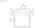
- FIG. 2 is a sectional view schematically showing the battery pack according to the first embodiment of the present disclosure.
- the battery pack according to the first embodiment of the present disclosure includes a housing unit 100 having an inner space, electrode terminals 210 and 220 exposed outside through through-holes (not shown) formed in the housing unit 100, and a battery module 300 disposed in the housing unit 100, the battery module having a plurality of battery cells 310.
- the electrode terminals 210 and 220 may be configured so as to be exposed upwards in FIG. 1 .
- the housing unit 100 may have a roughly rectangular parallelepiped shape; however, the present invention is not limited as to the shape of the housing unit 100.
- the housing unit 100 serves to protect the battery module 300 from the external environment.
- the housing unit 100 includes a first housing (an upper housing) 110 and a second housing (a lower housing) 120.
- the first housing 110 and the second housing 120 are coupled to each other such that the inner space, which is configured to receive the battery module 300, is formed in the housing unit 100.
- the plurality of battery cells 310 may be received in the second housing 120.
- each of the battery cells 310 may be a pouch-type battery cell.
- the pouch-type battery cell 310 may include an electrode assembly configured by stacking a plurality of electrode plates in the state in which a separator is disposed therebetween and a pouch configured to wrap the electrode assembly.
- the second housing 120 may have a battery cell receiving space having a width and a height corresponding respectively to the width and the length of each of the battery cells 310.
- Each of the first housing 110 and the second housing 120 may be made of plastic.
- the first housing 110 and the second housing 120 are joined to each other by welding (for example, ultrasonic welding or laser welding).
- welding for example, ultrasonic welding or laser welding.
- the interior of the housing unit 100 may have a dustproof and waterproof structure.
- the first housing 110 includes a first contact surface 111 continuously formed along a circumferential direction of the first housing 110.
- the second housing 120 includes a second contact surface 121 continuously formed along a circumferential direction of the second housing 120 and opposite the first contact surface 111 of the first housing 110.
- the first contact surface 111 of the first housing 110 and the second contact surface 121 of the second housing 120 have shapes corresponding to each other and are formed to closely contact each other.
- the first contact surface 111 and the second contact surface 121 each function as a welding surface.
- the first contact surface 111 and the second contact surface 121 are welded while being pressed against each other.
- a material constituting the first contact surface 111 and a material constituting the second contact surface 121 are melted and fused to each other, and accordingly, the first housing 110 and the second housing 120 are coupled to each other.
- a battery pack assembly apparatus 400 configured to press and weld the first housing 110 and the second housing 120 against each other is provided so that the first contact surface 111 and the second contact surface 121 may be pressed against each other.
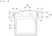
- FIG. 3 is a sectional view schematically showing a process of assembling a housing unit of the battery pack according to the first embodiment of the present disclosure, which is not part of the subject matter of the independent claims 1 and 2.
- the battery pack assembly apparatus 400 may include a first pressing module 410 in contact with the first housing 100, the first pressing module 410 configured to press the first housing 110 toward the second housing 120; a second pressing module 420 in contact with the second housing 120, the second pressing module 420 configured to press the second housing 120 toward the first housing 110; a control module (not shown) configured to control the first pressing module 410 and the second pressing module 420 to move in a direction adjacent to each other; and a welding module (not shown) configured to weld the first contact surface 111 of the first housing 110 and the second contact surface 121 of the second housing 120 pressed by the first pressing module 410 and the second pressing module 420 to each other.
- the first pressing module 410 and the second pressing module 420 may be configured to move adjacent to or spaced apart from each other by being connected to a linear movement mechanism such as, for example, an actuator operated by pneumatic or hydraulic pressure, a linear motor using electromagnetic interaction, or a ball screw device.
- the first pressing module 410 and the second pressing module 420 may move adjacent to each other to press the first housing 110 and the second housing 120 against each other.
- the welding module it may be configured to apply ultrasonic vibration or a laser beam to the first contact surface 111 of the first housing 110 and the second contact surface 121 of the second housing 120 pressed by the first pressing module 410 and the second pressing module 420.
- the first contact surface 111 and the second contact surface 121 may be pressed against each other to be in full contact. Since the first contact surface 111 and the second contact surface 121 may be in full contact, the first contact surface 111 and the second contact surface 121 may be uniformly welded.
- a first support 112 in contact with the first pressing module 410 may be provided on an outer surface of the first housing 110 so that the first housing 110 may be pressed by the first pressing module 410.
- the first support 112 may protrude outward from the outer surface of the first housing 110.
- the first support 112 may protrude outward from the outer surface of the first housing 110 and may be formed in a flange shape including the first contact surface 111.
- the first support 112 may protrude from the outer surface of the first housing 110 and extend continuously in the circumferential direction of the first housing 110 to form the first contact surface 111.
- a second support 122 in contact with the second pressing module 420 may be provided on an outer surface of the second housing 120 so that the second housing 120 may be pressed by the second pressing module 420.
- the second support 122 may protrude outward from the outer surface of the second housing 120.
- the second support 122 may protrude outward from the outer surface of the second housing 120 and may be formed in a flange shape including the second contact surface 121.
- the second support 122 may protrude from the outer surface of the second housing 120 and extend continuously in the circumferential direction of the second housing 120 to form the second contact surface 121.
- first pressing module 410 may be configured to extend in the circumferential direction of the first housing 110 to press the entire first support 112.
- second pressing module 420 may be configured to extend in the circumferential direction of the second housing 120 to press the entire second support 122.
- the first housing 110 and the second housing 120 constituting the housing unit 100 of the battery pack include the first support 112 and the second support 120, respectively.
- the first support 112 and the second support 122 are pressed against each other by the first pressing module 410 and the second pressing module 420 of the battery pack assembly apparatus 400, the first contact surface 111 of the first housing 110 and the second contact surface 121 of the second housing 120 may be in full contact. Therefore, since the first contact surface 111 and the second contact surface 121 may be welded to each other in close contact, the first contact surface 111 and the second contact surface 121 may be uniformly welded, and welding defects may be prevented from occurring.
- the first contact surface 111 and the second contact surface 121 may be pressed in closer contact with each other.
- the first support 112 and the second support 122 are formed in a flange shape including the first contact surface 111 and the second contact surface 121, respectively, the first contact surface 111 and the second contact surface 121 may be pressed in closer contact with each other as the first support 112 and the second support 122 are pressed by the first pressure module 410 and the second pressure module 420.
- FIG. 4 Components identical to the components of the first embodiment of the present disclosure as described above are denoted by the same reference numerals, and a detailed description thereof will be omitted.
- FIG. 4 is a sectional view schematically showing the battery pack according to the second embodiment of the present disclosure.
- a first support 112 in contact with a first pressing module 410 is provided on an outer surface of a first housing 110 so that the first housing 110 may be pressed by the first pressing module 410.
- the first support 112 has a rib shape protruding outward from the outer surface of the first housing 110.
- the first support 112 is disposed to be spaced apart from a second support 122.
- a first contact surface 111 is formed at an end portion extending downward from the first support 112.
- the first support 112 may extend continuously in a circumferential direction of the first housing 110.
- a plurality of the first supports 112 may be formed at predetermined intervals in the circumferential direction of the first housing 110.
- the second support 122 in contact with a second pressing module 420 is provided on an outer surface of a second housing 120 so that the second housing 120 may be pressed by the second pressing module 420.
- the second support 122 protrudes outward from the outer surface of the second housing 120.
- the second support 122 protrudes outward from the outer surface of the second housing 120 and is formed in a flange shape including a second contact surface 121.
- the second support 122 may protrude from the outer surface of the second housing 120 and extend continuously in a circumferential direction of the second housing 120 to form the second contact surface 121.
- the first contact surface 111 and the second contact surface 121 may be in close contact with each other by pressing the first support 112 and the second support 122 by the first pressing module 410 and the second pressing module 420, the first contact surface 111 and the second contact surface 121 may be uniformly welded.
- a position of the first support 112 of the first housing 110 according to a pressing position of the first pressing module 410 may be freely designed regardless of a position of the first contact surface 111.
- FIG. 5 Components identical to the components of the first and second embodiments of the present disclosure as described above are denoted by the same reference numerals, and a detailed description thereof will be omitted.
- FIG. 5 is a sectional view schematically showing the battery pack according to the third embodiment of the present disclosure, which is another embodiment of the present invention.
- a first support 112 in contact with a first pressing module 410 is provided on an outer surface of a first housing 110 so that the first housing 110 may be pressed by the first pressing module 410.
- the first support 112 protrudes outward from the outer surface of the first housing 110.
- the first support 112 protrudes outward from the outer surface of the first housing 110 and is formed in a flange shape including a first contact surface 111.
- the first support 112 may protrude from the outer surface of the first housing 110 and extend continuously in a circumferential direction of the first housing 110 to form the first contact surface 111.
- a second support 122 in contact with a second pressing module 420 is provided on an outer surface of a second housing 120 so that the second housing 120 may be pressed by the second pressing module 420.
- the second support 122 has a rib shape protruding outward from an outer surface of the second housing 120.
- the second support 122 is disposed to be spaced apart from the first support 112.
- a second contact surface 121 is formed at an end portion extending upward from the second support 122.
- the second support 122 may extend continuously in a circumferential direction of the second housing 120.
- a plurality of the second supports 122 may be formed at predetermined intervals in the circumferential direction of the second housing 120.
- a position of the second support 122 of the second housing 120 according to a pressing position of the second pressing module 420 may be freely designed regardless of a position of the second contact surface 121.
- the battery pack according to the embodiment of the present disclosure may be applied to a device including the battery pack as a power source.
- the device may be a computer, a cellular phone, a wearable electronic device, a power tool, an electric vehicle (EV), a hybrid electric vehicle, a plug-in hybrid electric vehicle, an electric two-wheeled vehicle, an electric golf cart, or an energy storage apparatus.
- the energy storage apparatus may be applied to various fields or places, such as a smart-grid system configured to control the supply and demand of electric power or a charging station for electric vehicles.
Landscapes
- Chemical & Material Sciences (AREA)
- Chemical Kinetics & Catalysis (AREA)
- Electrochemistry (AREA)
- General Chemical & Material Sciences (AREA)
- Engineering & Computer Science (AREA)
- Physics & Mathematics (AREA)
- Optics & Photonics (AREA)
- Mechanical Engineering (AREA)
- Manufacturing & Machinery (AREA)
- Battery Mounting, Suspending (AREA)
Description
- The present invention relates to a battery pack and a battery pack assembly apparatus used to assemble a battery pack.
- This application claims the benefit of priority to
Korean Patent Application No. 2019-0000643 filed on January 3, 2019 - In recent years, with an increase in the demand for portable electronic devices, such as laptop computers, smartphones, and tablet computers, research has been actively conducted on high-performance secondary batteries that are capable of being repeatedly charged and discharged.
- In addition, secondary batteries have come to be widely used in medium- or large-sized devices, such as vehicles, robots, and satellites, as well as small-sized devices, such as portable electronic devices. In particular, as fossil fuels are being depleted and increasing attention is being paid to environmental pollution, research on hybrid vehicles and electric vehicles is being actively conducted. The most essential part of a hybrid vehicle or an electric vehicle is a battery pack configured to supply electric power to a motor. The battery pack includes a battery module including a plurality of battery cells, wherein the plurality of battery cells is connected to each other in series and/or in parallel, whereby the capacity and output of the battery module are increased.
- Basically, a battery cell is manufactured through a process of stacking a plurality of electrode plates in the state in which a separator is disposed therebetween and welding a plurality of electrode tabs to the plurality of electrode plates, respectively, to form an electrode assembly and wrapping the electrode assembly in an aluminum pouch so as to be sealed.
- The battery pack includes a housing unit configured to receive a battery cell. The housing unit is composed of an upper housing and a lower housing, and the housing unit is assembled by coupling the upper housing and the lower housing to each other.
- In the process of assembling the housing unit, the upper housing is pressed against the lower housing by a jig while a contact surface of the upper housing and a contact surface of the lower housing are in contact with each other. In this state, the housing unit is assembled by welding the contact surface of the upper housing and the contact surface of the lower housing to each other.
- In the case of a conventional battery pack, only an upper housing is pressed by a jig in the process of assembling a housing unit, and thus, a contact surface of the upper housing and a contact surface of a lower housing may not be in full contact. Therefore, a problem may arise in which the contact surface of the upper housing and the contact surface of the lower housing are not properly welded to each other.
- In addition, in the case of the conventional battery pack, only the upper housing is pressed by the jig in the process of assembling the housing unit, and thus, the pressing force for pressing the upper housing may vary depending on an operator. Therefore, since the welding state between the upper housing and the lower housing may vary depending on the operator, a problem may arise in which the quality of the battery pack is not constant.
-
- The present invention has been made in view of the above problems, and it is an object of the present invention to provide a battery pack in which a first housing and a second housing constituting a housing unit are configured to press together against each other, thereby improving the welding quality between the first housing and the second housing.
- It is a further object of the present disclosure to provide a battery pack assembly apparatus configured to press the first housing and the second housing against each other using a first pressing module and a second pressing module, thereby improving the welding quality between the first housing and the second housing.
- The solution is provided by the subject matter of independent claims. Further embodiments are claimed in dependent claims.
- A battery pack according to embodiments of the present invention provided to accomplish the above object includes a housing unit configured to receive a battery cell therein, the housing unit comprising a first housing including a first contact surface; and a second housing including a second contact surface opposite the first contact surface, wherein the first housing and the second housing are coupled by welding in a state in which the first contact surface and the second contact surface are in contact with each other and pressed against each other, a first support is provided on an outer surface of the first housing, the first support contacting a first pressing module that presses the first housing toward the second housing, and a second support is provided on an outer surface of the second housing, the second support contacting a second pressing module that presses the second housing toward the first housing.
- The first support protrudes outward from the outer surface of the first housing and in some embodiments is formed in a flange shape including the first contact surface.
- The second support protrudes outward from the outer surface of the second housing and in some embodiments is formed in a flange shape including the second contact surface.
- The first support in some embodiments is formed in a rib shape protruding outward from the outer surface of the first housing.
- The second support in some embodiments is formed in a rib shape protruding outward from the outer surface of the second housing.
- A battery pack assembly apparatus according to the present disclosure provided to accomplish the above object may be configured to assemble a battery pack comprising a housing unit configured to receive a battery cell therein and including a first housing and a second housing, and may include a first pressing module coupled to a first support formed on an outer surface of the first housing; and a second pressing module coupled to a second support formed on an outer surface of the second housing, wherein the first pressing module and the second pressing module may be moved in a direction adjacent to each other to press the first housing and the second housing against each other.
- The first support may protrude from the outer surface of the first housing and may extend in a circumferential direction of the first housing. The first pressing module may be configured to extend in the circumferential direction of the first housing to press the entire first support.
- The second support may protrude from the outer surface of the second housing and may extend in a circumferential direction of the second housing. The second pressing module may be configured to extend in the circumferential direction of the second housing to press the entire second support.
- According to a battery pack according to an embodiment of the present invention, a first housing and a second housing constituting a housing unit of the battery pack include a first support and a second support, respectively. As the first support and the second support are pressed against each other by a first pressing module and a second pressing module of a battery pack assembly apparatus, a first contact surface of the first housing and a second contact surface of the second housing may be in close contact. Therefore, since the first contact surface and the second contact surface may be welded to each other in close contact, the first contact surface and the second contact surface may be welded uniformly, and welding defects may be prevented from occurring.
- The following drawings appended to this specification are provided to illustrate preferred embodiments of the present invention and to aid in understanding the technical idea of the present invention together with the detailed description of the invention, a description of which will follow, and the present invention should not be interpreted as being limited only to matters described in the drawings.
-
FIG. 1 is a perspective view schematically showing a battery pack according to a first embodiment of the present disclosure and an example useful for understanding the background of the present invention. -
FIG. 2 is a sectional view schematically showing the battery pack according to the first embodiment which is not part of the claimed invention. -
FIG. 3 is a sectional view schematically showing a process of assembling a housing unit of the battery pack according to the first embodiment which is not part of the claimed invention. -
FIG. 4 is a sectional view schematically showing a battery pack according to a second embodiment of the present disclosure which is an embodiment of the present invention. -
FIG. 5 is a sectional view schematically showing a battery pack according to a third embodiment of the present disclosure which is another embodiment of the present invention. - Hereinafter, a battery pack and a battery pack assembling apparatus according to an embodiment of the present disclosure and invention will be described with reference to the accompanying drawings.
- Embodiments of the present invention are provided in order to more completely describe the present invention to a person having ordinary skill in the art, and therefore the shape and size of each element in the drawings may be exaggerated, omitted, or schematically illustrated for clearer description. Consequently, the size or rate of each element does not entirely reflect the actual size or rate thereof.
- Hereinafter, the preferred embodiments of the present invention will be described in detail with reference to the accompanying drawings. It should be noted that terms or words used in this specification and the claims are not to be interpreted as having ordinary and dictionary-based meanings but as having meanings and concepts coinciding with the technical idea of the present invention based on the principle that the inventors may properly define the concepts of the terms in order to explain the invention in the best method.
-
FIG. 1 is a perspective view schematically showing a battery pack according to a first embodiment of the present disclosure, andFIG. 2 is a sectional view schematically showing the battery pack according to the first embodiment of the present disclosure. - As shown in
FIGS. 1 and2 , the battery pack according to the first embodiment of the present disclosure includes ahousing unit 100 having an inner space,electrode terminals housing unit 100, and abattery module 300 disposed in thehousing unit 100, the battery module having a plurality ofbattery cells 310. - As shown in
FIG. 1 , theelectrode terminals FIG. 1 . - As shown in
FIG. 1 , thehousing unit 100 may have a roughly rectangular parallelepiped shape; however, the present invention is not limited as to the shape of thehousing unit 100. Thehousing unit 100 serves to protect thebattery module 300 from the external environment. - The
housing unit 100 includes a first housing (an upper housing) 110 and a second housing (a lower housing) 120. Thefirst housing 110 and thesecond housing 120 are coupled to each other such that the inner space, which is configured to receive thebattery module 300, is formed in thehousing unit 100. - The plurality of
battery cells 310 may be received in thesecond housing 120. For example, each of thebattery cells 310 may be a pouch-type battery cell. The pouch-type battery cell 310 may include an electrode assembly configured by stacking a plurality of electrode plates in the state in which a separator is disposed therebetween and a pouch configured to wrap the electrode assembly. Thesecond housing 120 may have a battery cell receiving space having a width and a height corresponding respectively to the width and the length of each of thebattery cells 310. - Each of the
first housing 110 and thesecond housing 120 may be made of plastic. Thefirst housing 110 and thesecond housing 120 are joined to each other by welding (for example, ultrasonic welding or laser welding). As thefirst housing 110 and thesecond housing 120 are joined to each other by welding, the interior of thehousing unit 100 may have a dustproof and waterproof structure. - The
first housing 110 includes afirst contact surface 111 continuously formed along a circumferential direction of thefirst housing 110. Thesecond housing 120 includes asecond contact surface 121 continuously formed along a circumferential direction of thesecond housing 120 and opposite thefirst contact surface 111 of thefirst housing 110. Thefirst contact surface 111 of thefirst housing 110 and thesecond contact surface 121 of thesecond housing 120 have shapes corresponding to each other and are formed to closely contact each other. - The
first contact surface 111 and thesecond contact surface 121 each function as a welding surface. Thefirst contact surface 111 and thesecond contact surface 121 are welded while being pressed against each other. For example, when ultrasonic vibration or a laser beam is applied between thefirst contact surface 111 and thesecond contact surface 121 in a state where thefirst contact surface 111 and thesecond contact surface 121 are in close contact with each other, a material constituting thefirst contact surface 111 and a material constituting thesecond contact surface 121 are melted and fused to each other, and accordingly, thefirst housing 110 and thesecond housing 120 are coupled to each other. - A battery
pack assembly apparatus 400 configured to press and weld thefirst housing 110 and thesecond housing 120 against each other is provided so that thefirst contact surface 111 and thesecond contact surface 121 may be pressed against each other. -
FIG. 3 is a sectional view schematically showing a process of assembling a housing unit of the battery pack according to the first embodiment of the present disclosure, which is not part of the subject matter of the independent claims 1 and 2. - As shown in
FIG. 3 , the batterypack assembly apparatus 400 may include a firstpressing module 410 in contact with thefirst housing 100, the firstpressing module 410 configured to press thefirst housing 110 toward thesecond housing 120; a secondpressing module 420 in contact with thesecond housing 120, the secondpressing module 420 configured to press thesecond housing 120 toward thefirst housing 110; a control module (not shown) configured to control the firstpressing module 410 and the secondpressing module 420 to move in a direction adjacent to each other; and a welding module (not shown) configured to weld thefirst contact surface 111 of thefirst housing 110 and thesecond contact surface 121 of thesecond housing 120 pressed by the firstpressing module 410 and the secondpressing module 420 to each other. - The first
pressing module 410 and the secondpressing module 420 may be configured to move adjacent to or spaced apart from each other by being connected to a linear movement mechanism such as, for example, an actuator operated by pneumatic or hydraulic pressure, a linear motor using electromagnetic interaction, or a ball screw device. The firstpressing module 410 and the secondpressing module 420 may move adjacent to each other to press thefirst housing 110 and thesecond housing 120 against each other. - As the welding module, it may be configured to apply ultrasonic vibration or a laser beam to the
first contact surface 111 of thefirst housing 110 and thesecond contact surface 121 of thesecond housing 120 pressed by the firstpressing module 410 and the secondpressing module 420. - Since the
first housing 110 and thesecond housing 120 are pressed against each other by the firstpressing module 410 and the secondpressing module 420, thefirst contact surface 111 and thesecond contact surface 121 may be pressed against each other to be in full contact. Since thefirst contact surface 111 and thesecond contact surface 121 may be in full contact, thefirst contact surface 111 and thesecond contact surface 121 may be uniformly welded. - As shown in
FIG. 3 , which is not part of the subject matter of the independent claims 1 and 2, afirst support 112 in contact with the firstpressing module 410 may be provided on an outer surface of thefirst housing 110 so that thefirst housing 110 may be pressed by the firstpressing module 410. Thefirst support 112 may protrude outward from the outer surface of thefirst housing 110. For example, thefirst support 112 may protrude outward from the outer surface of thefirst housing 110 and may be formed in a flange shape including thefirst contact surface 111. In this case, thefirst support 112 may protrude from the outer surface of thefirst housing 110 and extend continuously in the circumferential direction of thefirst housing 110 to form thefirst contact surface 111. - In addition, as shown in
FIG. 3 , asecond support 122 in contact with the secondpressing module 420 may be provided on an outer surface of thesecond housing 120 so that thesecond housing 120 may be pressed by the secondpressing module 420. Thesecond support 122 may protrude outward from the outer surface of thesecond housing 120. For example, thesecond support 122 may protrude outward from the outer surface of thesecond housing 120 and may be formed in a flange shape including thesecond contact surface 121. In this case, thesecond support 122 may protrude from the outer surface of thesecond housing 120 and extend continuously in the circumferential direction of thesecond housing 120 to form thesecond contact surface 121. - For example, the first
pressing module 410 may be configured to extend in the circumferential direction of thefirst housing 110 to press the entirefirst support 112. Similarly, the secondpressing module 420 may be configured to extend in the circumferential direction of thesecond housing 120 to press the entiresecond support 122. - According to the battery pack according to the first embodiment of the present disclosure, the
first housing 110 and thesecond housing 120 constituting thehousing unit 100 of the battery pack include thefirst support 112 and thesecond support 120, respectively. As thefirst support 112 and thesecond support 122 are pressed against each other by the firstpressing module 410 and the secondpressing module 420 of the batterypack assembly apparatus 400, thefirst contact surface 111 of thefirst housing 110 and thesecond contact surface 121 of thesecond housing 120 may be in full contact. Therefore, since thefirst contact surface 111 and thesecond contact surface 121 may be welded to each other in close contact, thefirst contact surface 111 and thesecond contact surface 121 may be uniformly welded, and welding defects may be prevented from occurring. - In addition, according to the battery pack according to the first embodiment of the present disclosure, since the pressing forces of the first
pressing module 410 and the secondpressing module 420 are transmitted to the entirefirst support 112 and the entiresecond support 122, thefirst contact surface 111 and thesecond contact surface 121 may be pressed in closer contact with each other. - In addition, according to the battery pack according to the first embodiment of the present disclosure, since the
first support 112 and thesecond support 122 are formed in a flange shape including thefirst contact surface 111 and thesecond contact surface 121, respectively, thefirst contact surface 111 and thesecond contact surface 121 may be pressed in closer contact with each other as thefirst support 112 and thesecond support 122 are pressed by thefirst pressure module 410 and thesecond pressure module 420. - Hereinafter, a battery pack according to a second embodiment of the present disclosure and an embodiment of the invention will be described with reference to
FIG. 4 . Components identical to the components of the first embodiment of the present disclosure as described above are denoted by the same reference numerals, and a detailed description thereof will be omitted. -
FIG. 4 is a sectional view schematically showing the battery pack according to the second embodiment of the present disclosure. - As shown in
FIG. 4 , in the case of battery pack according to the second embodiment of the present disclosure, afirst support 112 in contact with a firstpressing module 410 is provided on an outer surface of afirst housing 110 so that thefirst housing 110 may be pressed by the firstpressing module 410. Thefirst support 112 has a rib shape protruding outward from the outer surface of thefirst housing 110. Thefirst support 112 is disposed to be spaced apart from asecond support 122. Afirst contact surface 111 is formed at an end portion extending downward from thefirst support 112. In accordance with the independent claim 1, thefirst support 112 may extend continuously in a circumferential direction of thefirst housing 110. Alternatively in accordance with the independent claim 1, a plurality of thefirst supports 112 may be formed at predetermined intervals in the circumferential direction of thefirst housing 110. - In addition, the
second support 122 in contact with a secondpressing module 420 is provided on an outer surface of asecond housing 120 so that thesecond housing 120 may be pressed by the secondpressing module 420. Thesecond support 122 protrudes outward from the outer surface of thesecond housing 120. For example, thesecond support 122 protrudes outward from the outer surface of thesecond housing 120 and is formed in a flange shape including asecond contact surface 121. In this case, thesecond support 122 may protrude from the outer surface of thesecond housing 120 and extend continuously in a circumferential direction of thesecond housing 120 to form thesecond contact surface 121. - According to the battery pack according to the second embodiment of the present disclosure, since the
first contact surface 111 and thesecond contact surface 121 may be in close contact with each other by pressing thefirst support 112 and thesecond support 122 by the firstpressing module 410 and the secondpressing module 420, thefirst contact surface 111 and thesecond contact surface 121 may be uniformly welded. - In addition, according to the battery pack according to the second embodiment of the present disclosure, since the
first contact surface 111 of thefirst housing 110 and thefirst support 112 of thefirst housing 110 are separately formed, a position of thefirst support 112 of thefirst housing 110 according to a pressing position of the firstpressing module 410 may be freely designed regardless of a position of thefirst contact surface 111. - Hereinafter, a battery pack according to a third embodiment of the present disclosure will be described with reference to
FIG. 5 . Components identical to the components of the first and second embodiments of the present disclosure as described above are denoted by the same reference numerals, and a detailed description thereof will be omitted. -
FIG. 5 is a sectional view schematically showing the battery pack according to the third embodiment of the present disclosure, which is another embodiment of the present invention. - As shown in
FIG. 5 , in the case of the battery pack according to the third embodiment of the present disclosure, afirst support 112 in contact with a firstpressing module 410 is provided on an outer surface of afirst housing 110 so that thefirst housing 110 may be pressed by the firstpressing module 410. Thefirst support 112 protrudes outward from the outer surface of thefirst housing 110. In accordance with the independent claim 2 thefirst support 112 protrudes outward from the outer surface of thefirst housing 110 and is formed in a flange shape including afirst contact surface 111. In this case, thefirst support 112 may protrude from the outer surface of thefirst housing 110 and extend continuously in a circumferential direction of thefirst housing 110 to form thefirst contact surface 111. - In addition, a
second support 122 in contact with a secondpressing module 420 is provided on an outer surface of asecond housing 120 so that thesecond housing 120 may be pressed by the secondpressing module 420. Thesecond support 122 has a rib shape protruding outward from an outer surface of thesecond housing 120. Thesecond support 122 is disposed to be spaced apart from thefirst support 112. Asecond contact surface 121 is formed at an end portion extending upward from thesecond support 122. In accordance with the independent claim 2, thesecond support 122 may extend continuously in a circumferential direction of thesecond housing 120. Alternatively in accordance with the independent claim 2, a plurality of thesecond supports 122 may be formed at predetermined intervals in the circumferential direction of thesecond housing 120. - According to the battery pack according to the third embodiment of the present disclosure, since the
first contact surface 111 and thesecond contact surface 121 may be in close contact with each other by pressing thefirst support 112 and thesecond support 122 by the firstpressing module 410 and the secondpressing module 420, thefirst contact surface 111 and thesecond contact surface 121 may be uniformly welded. - In addition, according to the battery pack according to the third embodiment of the present disclosure, since the
second contact surface 121 of thesecond housing 120 and thesecond support 122 of thesecond housing 120 are separately formed, a position of thesecond support 122 of thesecond housing 120 according to a pressing position of the secondpressing module 420 may be freely designed regardless of a position of thesecond contact surface 121. - The battery pack according to the embodiment of the present disclosure may be applied to a device including the battery pack as a power source.
- For example, the device may be a computer, a cellular phone, a wearable electronic device, a power tool, an electric vehicle (EV), a hybrid electric vehicle, a plug-in hybrid electric vehicle, an electric two-wheeled vehicle, an electric golf cart, or an energy storage apparatus. The energy storage apparatus may be applied to various fields or places, such as a smart-grid system configured to control the supply and demand of electric power or a charging station for electric vehicles.
- The preferred embodiments of the present invention have been described illustratively; however, the scope of the present invention is not limited to such specific embodiments, and may be appropriately changed within the scope defined in the claims.
Claims (4)
- A battery pack comprising:
a housing unit (100) configured to receive a battery cell therein, the housing unit comprising:a first housing (110) including a first contact surface (111); anda second housing (120) including a second contact surface (121) opposite the first contact surface (111), whereinthe first housing (110) and the second housing (120) are coupled by welding in a state in which the first contact surface (111) and the second contact surface (121) are in contact with each other and pressed against each other,a first support (112) is provided on an outer surface of the first housing (110), the first support (112) being configured for contacting a first pressing module (410) that presses the first housing (110) toward the second housing (120), anda second support (122) is provided on an outer surface of the second housing, the second support (122) being configured for contacting a second pressing module (420) that presses the second housing (120) toward the first housing (110),wherein the second support (122) protrudes outward from the outer surface of the second housing (120) and is formed in a flange shape including the second contact surface (121),the first support (112) is formed in a rib shape protruding outward from the outer surface of the first housing (110),the first support (112) is disposed so that it is spaced apart from the second support (122),the first contact surface (111) is formed at an end portion extending downward from the first support (112),and whereinthe first support (112) extends continuously in a circumferential direction of the first housing (110) or a plurality of the first supports (112) is formed at predetermined intervals in the circumferential direction of the first housing (110). - A battery pack comprising:
a housing unit (100) configured to receive a battery cell therein, the housing unit comprising:a first housing (110) including a first contact surface (111); anda second housing (120) including a second contact surface (121) opposite the first contact surface (111), whereinthe first housing (110) and the second housing (120) are coupled by welding in a state in which the first contact surface (111) and the second contact surface (121) are in contact with each other and pressed against each other,a first support (112) is provided on an outer surface of the first housing (110), the first support (112) being configured for contacting a first pressing module (410) that presses the first housing (110) toward the second housing (120), anda second support (122) is provided on an outer surface of the second housing, the second support (122) being configured for contacting a second pressing module (420) that presses the second housing (120) toward the first housing (110),wherein the first support (112) protrudes outward from the outer surface of the first housing (110) and is formed in a flange shape including the first contact surface (111),wherein the second support (122) is formed in a rib shape protruding outward from the outer surface of the second housing (120),the second support (122) is disposed so that it is spaced apart from the first support (112),the second contact surface (121) is formed at an end portion extending upward from the second support (122), and whereinthe second support (122) extends continuously in a circumferential direction of the second housing (120) or a plurality of the second supports (122) is formed at predetermined intervals in the circumferential direction of the second housing (120). - A device having the battery pack according to any one of claims 1 or 2.
- The device according to claim 3, wherein the device is one of a computer, a cellular phone, a wearable electronic device, a power tool, an electric vehicle (EV), a hybrid electric vehicle, a plug-in hybrid electric vehicle, an electric two-wheeled vehicle, an electric golf cart, and an energy storage apparatus.
Applications Claiming Priority (2)
| Application Number | Priority Date | Filing Date | Title |
|---|---|---|---|
| KR1020190000643A KR102407165B1 (en) | 2019-01-03 | 2019-01-03 | Battery pack and apparatus for assembling battery pack |
| PCT/KR2020/000136 WO2020141942A1 (en) | 2019-01-03 | 2020-01-03 | Battery pack and battery pack assembly device |
Publications (3)
| Publication Number | Publication Date |
|---|---|
| EP3758094A1 EP3758094A1 (en) | 2020-12-30 |
| EP3758094A4 EP3758094A4 (en) | 2021-09-08 |
| EP3758094B1 true EP3758094B1 (en) | 2025-06-18 |
Family
ID=71407066
Family Applications (1)
| Application Number | Title | Priority Date | Filing Date |
|---|---|---|---|
| EP20735998.5A Active EP3758094B1 (en) | 2019-01-03 | 2020-01-03 | Battery pack and battery pack assembly apparatus |
Country Status (8)
| Country | Link |
|---|---|
| US (1) | US20210242526A1 (en) |
| EP (1) | EP3758094B1 (en) |
| JP (1) | JP7055307B2 (en) |
| KR (1) | KR102407165B1 (en) |
| CN (1) | CN111868960B (en) |
| ES (1) | ES3035013T3 (en) |
| HU (1) | HUE071999T2 (en) |
| WO (1) | WO2020141942A1 (en) |
Families Citing this family (4)
| Publication number | Priority date | Publication date | Assignee | Title |
|---|---|---|---|---|
| CN112247356B (en) * | 2020-09-30 | 2023-06-13 | 江苏逸飞激光设备有限公司 | Current collecting disc welding production line |
| KR102952459B1 (en) * | 2020-10-13 | 2026-04-13 | 주식회사 엘지에너지솔루션 | Battery pack assembly guide jig |
| ES3042286T3 (en) | 2020-11-23 | 2025-11-19 | Lg Energy Solution Ltd | Battery pack case including over-fusion prevention structure |
| WO2024077414A1 (en) * | 2022-10-09 | 2024-04-18 | 宁德新能源科技有限公司 | Battery pack |
Family Cites Families (18)
| Publication number | Priority date | Publication date | Assignee | Title |
|---|---|---|---|---|
| JP2004103369A (en) * | 2002-09-09 | 2004-04-02 | Matsushita Electric Ind Co Ltd | Flat battery and method of manufacturing the same |
| DE102005013351B4 (en) * | 2005-03-23 | 2007-12-20 | Diehl Aerospace Gmbh | Device for emergency power supply |
| JP2009146645A (en) * | 2007-12-12 | 2009-07-02 | Toyota Motor Corp | Welded structure manufacturing method and battery manufacturing method |
| JP4325721B2 (en) * | 2008-01-18 | 2009-09-02 | トヨタ自動車株式会社 | Temperature control mechanism |
| JP5521964B2 (en) * | 2010-10-07 | 2014-06-18 | トヨタ自動車株式会社 | Battery module |
| JP2012094358A (en) | 2010-10-27 | 2012-05-17 | Nisshin Steel Co Ltd | Manufacturing method of metal closed bottom or sealed container |
| CN103537813B (en) * | 2013-09-26 | 2015-10-28 | 奇瑞新能源汽车技术有限公司 | A kind of using method of high-capacity dynamical lithium-ion battery case weld fixture |
| US10218027B2 (en) * | 2013-11-11 | 2019-02-26 | A123 Systems, LLC | Vehicle starter battery |
| EP3128576A4 (en) * | 2014-03-31 | 2017-11-01 | Nec Corporation | Storage battery unit and storage battery device provided with same |
| JP6260487B2 (en) * | 2014-07-31 | 2018-01-17 | 株式会社Gsユアサ | Power storage device |
| US20160104921A1 (en) * | 2014-10-08 | 2016-04-14 | Ford Global Technologies, Llc | Battery module |
| US20160344059A1 (en) * | 2015-05-18 | 2016-11-24 | Johnson Controls Technology Company | System and method for lithium-ion battery module assembly via heat seal of cover to base of housing |
| CN205429015U (en) * | 2015-12-31 | 2016-08-03 | 深圳市大富精工有限公司 | Battery and battery case thereof |
| CN206076305U (en) | 2016-08-12 | 2017-04-05 | 宁德时代新能源科技股份有限公司 | cabinet |
| KR102635431B1 (en) * | 2016-12-13 | 2024-02-07 | 주식회사 엘지에너지솔루션 | Cartridge for battery cell and Battery module having the same |
| KR20190000643A (en) | 2017-06-23 | 2019-01-03 | 주식회사 만도 | Method and apparatus for improving response of active roll stabilizer for vehicle |
| CN207771032U (en) * | 2018-01-26 | 2018-08-28 | 东莞市星马焊锡有限公司 | A fully automatic aluminum shell battery cover plate welding machine |
| CN207997064U (en) * | 2018-03-09 | 2018-10-23 | 武汉逸飞激光智能装备有限公司 | A kind of battery case cap welding equipment |
-
2019
- 2019-01-03 KR KR1020190000643A patent/KR102407165B1/en active Active
-
2020
- 2020-01-03 CN CN202080001830.XA patent/CN111868960B/en active Active
- 2020-01-03 ES ES20735998T patent/ES3035013T3/en active Active
- 2020-01-03 JP JP2020546107A patent/JP7055307B2/en active Active
- 2020-01-03 WO PCT/KR2020/000136 patent/WO2020141942A1/en not_active Ceased
- 2020-01-03 US US17/052,843 patent/US20210242526A1/en active Pending
- 2020-01-03 HU HUE20735998A patent/HUE071999T2/en unknown
- 2020-01-03 EP EP20735998.5A patent/EP3758094B1/en active Active
Also Published As
| Publication number | Publication date |
|---|---|
| CN111868960A (en) | 2020-10-30 |
| ES3035013T3 (en) | 2025-08-27 |
| WO2020141942A1 (en) | 2020-07-09 |
| EP3758094A4 (en) | 2021-09-08 |
| KR20200084579A (en) | 2020-07-13 |
| KR102407165B1 (en) | 2022-06-10 |
| JP2021516426A (en) | 2021-07-01 |
| HUE071999T2 (en) | 2025-10-28 |
| EP3758094A1 (en) | 2020-12-30 |
| JP7055307B2 (en) | 2022-04-18 |
| US20210242526A1 (en) | 2021-08-05 |
| CN111868960B (en) | 2022-09-23 |
Similar Documents
| Publication | Publication Date | Title |
|---|---|---|
| EP3758094B1 (en) | Battery pack and battery pack assembly apparatus | |
| CN111587496B (en) | Battery module including heat shrinkable tube | |
| KR101328354B1 (en) | Lithium ion secondary battery, vehicle, and device equipped with battery | |
| US9876207B2 (en) | Battery module | |
| EP4184669B1 (en) | Battery cell and manufacturing method and manufacturing system therefor, battery, and power consuming device | |
| EP3561902B1 (en) | Battery module, battery pack comprising battery module, and vehicle comprising battery pack | |
| US20250391972A1 (en) | Battery cell including end cap with protruding structure, method and system for manufacturing same, battery, and electrical device | |
| KR20170130091A (en) | Lead welding apparatus, battery module manufactured by the lead welding apparatus and battery pack comprising the battery module | |
| KR20150062777A (en) | Battery module and battery pack including the same | |
| JP2020513661A (en) | Battery module | |
| KR102263480B1 (en) | Pouch-type Secondary Battery Having Preliminary Cutting Line | |
| KR20160094909A (en) | Battery module and battery pack including the same | |
| KR20180073972A (en) | The fixed structure of battery module-pack housing using plastic laser welding | |
| KR20190135865A (en) | Battery module | |
| KR101381680B1 (en) | Battery Pack Comprising Charging Coil | |
| JP2017153233A (en) | Unmanned carrier and battery pack for unmanned carrier | |
| EP4096001A1 (en) | Battery pack, power storage device and vehicle | |
| JP2023532036A (en) | Battery modules, battery packs and automobiles | |
| US7485392B2 (en) | Rechargeable battery having impact buffer function | |
| KR20190135859A (en) | Battery module | |
| EP4379945B1 (en) | Battery module and battery pack and vehicle comprising the same | |
| EP4513642A1 (en) | Battery module case and battery module comprising same | |
| CN120380649A (en) | Battery assembly | |
| KR102302969B1 (en) | Secondary Battery Having Top Cap with Variable Coupling Structure | |
| KR20250146795A (en) | Electrode assembly, protective tape attachment apparatus and method |
Legal Events
| Date | Code | Title | Description |
|---|---|---|---|
| STAA | Information on the status of an ep patent application or granted ep patent |
Free format text: STATUS: THE INTERNATIONAL PUBLICATION HAS BEEN MADE |
|
| PUAI | Public reference made under article 153(3) epc to a published international application that has entered the european phase |
Free format text: ORIGINAL CODE: 0009012 |
|
| STAA | Information on the status of an ep patent application or granted ep patent |
Free format text: STATUS: REQUEST FOR EXAMINATION WAS MADE |
|
| 17P | Request for examination filed |
Effective date: 20200925 |
|
| AK | Designated contracting states |
Kind code of ref document: A1 Designated state(s): AL AT BE BG CH CY CZ DE DK EE ES FI FR GB GR HR HU IE IS IT LI LT LU LV MC MK MT NL NO PL PT RO RS SE SI SK SM TR |
|
| AX | Request for extension of the european patent |
Extension state: BA ME |
|
| RIC1 | Information provided on ipc code assigned before grant |
Ipc: H01M 50/244 20210101AFI20210422BHEP Ipc: H01M 10/04 20060101ALI20210422BHEP Ipc: B23K 37/04 20060101ALI20210422BHEP |
|
| REG | Reference to a national code |
Ref country code: DE Ref legal event code: R079 Ipc: H01M0050244000 Ref country code: DE Ref legal event code: R079 Ref document number: 602020052924 Country of ref document: DE Free format text: PREVIOUS MAIN CLASS: H01M0002100000 Ipc: H01M0050244000 |
|
| A4 | Supplementary search report drawn up and despatched |
Effective date: 20210806 |
|
| RIC1 | Information provided on ipc code assigned before grant |
Ipc: B23K 37/04 20060101ALI20210802BHEP Ipc: H01M 10/04 20060101ALI20210802BHEP Ipc: H01M 50/244 20210101AFI20210802BHEP |
|
| RAP1 | Party data changed (applicant data changed or rights of an application transferred) |
Owner name: LG ENERGY SOLUTION LTD. |
|
| RAP3 | Party data changed (applicant data changed or rights of an application transferred) |
Owner name: LG ENERGY SOLUTION, LTD. |
|
| DAV | Request for validation of the european patent (deleted) | ||
| DAX | Request for extension of the european patent (deleted) | ||
| STAA | Information on the status of an ep patent application or granted ep patent |
Free format text: STATUS: EXAMINATION IS IN PROGRESS |
|
| 17Q | First examination report despatched |
Effective date: 20221222 |
|
| GRAP | Despatch of communication of intention to grant a patent |
Free format text: ORIGINAL CODE: EPIDOSNIGR1 |
|
| STAA | Information on the status of an ep patent application or granted ep patent |
Free format text: STATUS: GRANT OF PATENT IS INTENDED |
|
| INTG | Intention to grant announced |
Effective date: 20250228 |
|
| P01 | Opt-out of the competence of the unified patent court (upc) registered |
Free format text: CASE NUMBER: APP_13940/2025 Effective date: 20250321 |
|
| GRAS | Grant fee paid |
Free format text: ORIGINAL CODE: EPIDOSNIGR3 |
|
| GRAA | (expected) grant |
Free format text: ORIGINAL CODE: 0009210 |
|
| STAA | Information on the status of an ep patent application or granted ep patent |
Free format text: STATUS: THE PATENT HAS BEEN GRANTED |
|
| AK | Designated contracting states |
Kind code of ref document: B1 Designated state(s): AL AT BE BG CH CY CZ DE DK EE ES FI FR GB GR HR HU IE IS IT LI LT LU LV MC MK MT NL NO PL PT RO RS SE SI SK SM TR |
|
| REG | Reference to a national code |
Ref country code: GB Ref legal event code: FG4D |
|
| REG | Reference to a national code |
Ref country code: CH Ref legal event code: EP |
|
| REG | Reference to a national code |
Ref country code: DE Ref legal event code: R096 Ref document number: 602020052924 Country of ref document: DE |
|
| REG | Reference to a national code |
Ref country code: CH Ref legal event code: EP |
|
| REG | Reference to a national code |
Ref country code: IE Ref legal event code: FG4D |
|
| REG | Reference to a national code |
Ref country code: ES Ref legal event code: FG2A Ref document number: 3035013 Country of ref document: ES Kind code of ref document: T3 Effective date: 20250827 |
|
| PG25 | Lapsed in a contracting state [announced via postgrant information from national office to epo] |
Ref country code: FI Free format text: LAPSE BECAUSE OF FAILURE TO SUBMIT A TRANSLATION OF THE DESCRIPTION OR TO PAY THE FEE WITHIN THE PRESCRIBED TIME-LIMIT Effective date: 20250618 |
|
| REG | Reference to a national code |
Ref country code: LT Ref legal event code: MG9D |
|
| PG25 | Lapsed in a contracting state [announced via postgrant information from national office to epo] |
Ref country code: NO Free format text: LAPSE BECAUSE OF FAILURE TO SUBMIT A TRANSLATION OF THE DESCRIPTION OR TO PAY THE FEE WITHIN THE PRESCRIBED TIME-LIMIT Effective date: 20250918 Ref country code: GR Free format text: LAPSE BECAUSE OF FAILURE TO SUBMIT A TRANSLATION OF THE DESCRIPTION OR TO PAY THE FEE WITHIN THE PRESCRIBED TIME-LIMIT Effective date: 20250919 |
|
| PG25 | Lapsed in a contracting state [announced via postgrant information from national office to epo] |
Ref country code: BG Free format text: LAPSE BECAUSE OF FAILURE TO SUBMIT A TRANSLATION OF THE DESCRIPTION OR TO PAY THE FEE WITHIN THE PRESCRIBED TIME-LIMIT Effective date: 20250618 |
|
| PG25 | Lapsed in a contracting state [announced via postgrant information from national office to epo] |
Ref country code: HR Free format text: LAPSE BECAUSE OF FAILURE TO SUBMIT A TRANSLATION OF THE DESCRIPTION OR TO PAY THE FEE WITHIN THE PRESCRIBED TIME-LIMIT Effective date: 20250618 |
|
| PG25 | Lapsed in a contracting state [announced via postgrant information from national office to epo] |
Ref country code: RS Free format text: LAPSE BECAUSE OF FAILURE TO SUBMIT A TRANSLATION OF THE DESCRIPTION OR TO PAY THE FEE WITHIN THE PRESCRIBED TIME-LIMIT Effective date: 20250918 |
|
| REG | Reference to a national code |
Ref country code: NL Ref legal event code: MP Effective date: 20250618 |
|
| REG | Reference to a national code |
Ref country code: HU Ref legal event code: AG4A Ref document number: E071999 Country of ref document: HU |
|
| PG25 | Lapsed in a contracting state [announced via postgrant information from national office to epo] |
Ref country code: LV Free format text: LAPSE BECAUSE OF FAILURE TO SUBMIT A TRANSLATION OF THE DESCRIPTION OR TO PAY THE FEE WITHIN THE PRESCRIBED TIME-LIMIT Effective date: 20250618 |
|
| PG25 | Lapsed in a contracting state [announced via postgrant information from national office to epo] |
Ref country code: NL Free format text: LAPSE BECAUSE OF FAILURE TO SUBMIT A TRANSLATION OF THE DESCRIPTION OR TO PAY THE FEE WITHIN THE PRESCRIBED TIME-LIMIT Effective date: 20250618 |
|
| PG25 | Lapsed in a contracting state [announced via postgrant information from national office to epo] |
Ref country code: PT Free format text: LAPSE BECAUSE OF FAILURE TO SUBMIT A TRANSLATION OF THE DESCRIPTION OR TO PAY THE FEE WITHIN THE PRESCRIBED TIME-LIMIT Effective date: 20251020 |
|
| REG | Reference to a national code |
Ref country code: AT Ref legal event code: MK05 Ref document number: 1805092 Country of ref document: AT Kind code of ref document: T Effective date: 20250618 |
|
| PG25 | Lapsed in a contracting state [announced via postgrant information from national office to epo] |
Ref country code: IS Free format text: LAPSE BECAUSE OF FAILURE TO SUBMIT A TRANSLATION OF THE DESCRIPTION OR TO PAY THE FEE WITHIN THE PRESCRIBED TIME-LIMIT Effective date: 20251018 |
|
| PGFP | Annual fee paid to national office [announced via postgrant information from national office to epo] |
Ref country code: GB Payment date: 20251222 Year of fee payment: 7 |
|
| PG25 | Lapsed in a contracting state [announced via postgrant information from national office to epo] |
Ref country code: SM Free format text: LAPSE BECAUSE OF FAILURE TO SUBMIT A TRANSLATION OF THE DESCRIPTION OR TO PAY THE FEE WITHIN THE PRESCRIBED TIME-LIMIT Effective date: 20250618 Ref country code: AT Free format text: LAPSE BECAUSE OF FAILURE TO SUBMIT A TRANSLATION OF THE DESCRIPTION OR TO PAY THE FEE WITHIN THE PRESCRIBED TIME-LIMIT Effective date: 20250618 |
|
| PGFP | Annual fee paid to national office [announced via postgrant information from national office to epo] |
Ref country code: FR Payment date: 20251223 Year of fee payment: 7 |
|
| PGFP | Annual fee paid to national office [announced via postgrant information from national office to epo] |
Ref country code: BE Payment date: 20251229 Year of fee payment: 7 |
|
| PG25 | Lapsed in a contracting state [announced via postgrant information from national office to epo] |
Ref country code: CZ Free format text: LAPSE BECAUSE OF FAILURE TO SUBMIT A TRANSLATION OF THE DESCRIPTION OR TO PAY THE FEE WITHIN THE PRESCRIBED TIME-LIMIT Effective date: 20250618 |
|
| PG25 | Lapsed in a contracting state [announced via postgrant information from national office to epo] |
Ref country code: PL Free format text: LAPSE BECAUSE OF FAILURE TO SUBMIT A TRANSLATION OF THE DESCRIPTION OR TO PAY THE FEE WITHIN THE PRESCRIBED TIME-LIMIT Effective date: 20250618 |
|
| PG25 | Lapsed in a contracting state [announced via postgrant information from national office to epo] |
Ref country code: EE Free format text: LAPSE BECAUSE OF FAILURE TO SUBMIT A TRANSLATION OF THE DESCRIPTION OR TO PAY THE FEE WITHIN THE PRESCRIBED TIME-LIMIT Effective date: 20250618 |
|
| PG25 | Lapsed in a contracting state [announced via postgrant information from national office to epo] |
Ref country code: RO Free format text: LAPSE BECAUSE OF FAILURE TO SUBMIT A TRANSLATION OF THE DESCRIPTION OR TO PAY THE FEE WITHIN THE PRESCRIBED TIME-LIMIT Effective date: 20250618 Ref country code: SK Free format text: LAPSE BECAUSE OF FAILURE TO SUBMIT A TRANSLATION OF THE DESCRIPTION OR TO PAY THE FEE WITHIN THE PRESCRIBED TIME-LIMIT Effective date: 20250618 |
|
| PGFP | Annual fee paid to national office [announced via postgrant information from national office to epo] |
Ref country code: HU Payment date: 20260129 Year of fee payment: 7 |
|
| REG | Reference to a national code |
Ref country code: DE Ref legal event code: R097 Ref document number: 602020052924 Country of ref document: DE |
|
| PGFP | Annual fee paid to national office [announced via postgrant information from national office to epo] |
Ref country code: ES Payment date: 20260212 Year of fee payment: 7 |
|
| PG25 | Lapsed in a contracting state [announced via postgrant information from national office to epo] |
Ref country code: DK Free format text: LAPSE BECAUSE OF FAILURE TO SUBMIT A TRANSLATION OF THE DESCRIPTION OR TO PAY THE FEE WITHIN THE PRESCRIBED TIME-LIMIT Effective date: 20250618 |
|
| PGFP | Annual fee paid to national office [announced via postgrant information from national office to epo] |
Ref country code: DE Payment date: 20251222 Year of fee payment: 7 |
|
| PG25 | Lapsed in a contracting state [announced via postgrant information from national office to epo] |
Ref country code: IT Free format text: LAPSE BECAUSE OF FAILURE TO SUBMIT A TRANSLATION OF THE DESCRIPTION OR TO PAY THE FEE WITHIN THE PRESCRIBED TIME-LIMIT Effective date: 20250618 |
|
| PLBE | No opposition filed within time limit |
Free format text: ORIGINAL CODE: 0009261 |
|
| STAA | Information on the status of an ep patent application or granted ep patent |
Free format text: STATUS: NO OPPOSITION FILED WITHIN TIME LIMIT |
|
| REG | Reference to a national code |
Ref country code: CH Ref legal event code: L10 Free format text: ST27 STATUS EVENT CODE: U-0-0-L10-L00 (AS PROVIDED BY THE NATIONAL OFFICE) Effective date: 20260430 |