EP3758042A1 - Monochromator and charged particle beam system - Google Patents
Monochromator and charged particle beam system Download PDFInfo
- Publication number
- EP3758042A1 EP3758042A1 EP20181438.1A EP20181438A EP3758042A1 EP 3758042 A1 EP3758042 A1 EP 3758042A1 EP 20181438 A EP20181438 A EP 20181438A EP 3758042 A1 EP3758042 A1 EP 3758042A1
- Authority
- EP
- European Patent Office
- Prior art keywords
- monochromator
- wien filter
- wien
- electron
- energy
- Prior art date
- Legal status (The legal status is an assumption and is not a legal conclusion. Google has not performed a legal analysis and makes no representation as to the accuracy of the status listed.)
- Granted
Links
Images


Classifications
-
- H—ELECTRICITY
- H01—ELECTRIC ELEMENTS
- H01J—ELECTRIC DISCHARGE TUBES OR DISCHARGE LAMPS
- H01J37/00—Discharge tubes with provision for introducing objects or material to be exposed to the discharge, e.g. for the purpose of examination or processing thereof
- H01J37/02—Details
- H01J37/04—Arrangements of electrodes and associated parts for generating or controlling the discharge, e.g. electron-optical arrangement or ion-optical arrangement
- H01J37/05—Electron or ion-optical arrangements for separating electrons or ions according to their energy or mass
-
- H—ELECTRICITY
- H01—ELECTRIC ELEMENTS
- H01J—ELECTRIC DISCHARGE TUBES OR DISCHARGE LAMPS
- H01J37/00—Discharge tubes with provision for introducing objects or material to be exposed to the discharge, e.g. for the purpose of examination or processing thereof
- H01J37/26—Electron or ion microscopes; Electron or ion diffraction tubes
- H01J37/28—Electron or ion microscopes; Electron or ion diffraction tubes with scanning beams
-
- H—ELECTRICITY
- H01—ELECTRIC ELEMENTS
- H01J—ELECTRIC DISCHARGE TUBES OR DISCHARGE LAMPS
- H01J2237/00—Discharge tubes exposing object to beam, e.g. for analysis treatment, etching, imaging
- H01J2237/05—Arrangements for energy or mass analysis
- H01J2237/057—Energy or mass filtering
Definitions
- the present invention relates to a monochromator and a charged particle beam system.
- Monochromators are used to achieve higher resolution in electron energy loss spectroscopy (EELS) implemented in transmission electron microscopy (TEM).
- EELS electron energy loss spectroscopy
- TEM transmission electron microscopy
- the maximum amount of information achievable by a transmission electron microscope (TEM) image can be improved by monochromatizing the electron rays by means of a monochromator.
- the morphology of a substance can be imaged and observed at atomic resolution.
- STEM scanning transmission electron microscopy
- HAADF-STEM high-angle annular dark field scanning transmission electron microscopy
- EELS EELS
- Monochromators of the single Wien filter type and monochromators of the double Wien filter type are known (see, for example, patent document 1).
- Patent document 1 JP-A-2001-357809
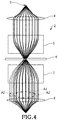
- FIG. 4 shows the configuration of a monochromator, 2, of the double Wien filter type.
- trajectories of electron rays with different energies are indicated by solid and broken lines.
- the monochromator 2 has a Wien filter 5, an energy-selecting slit 6, and another Wien filter 7.
- An electrostatic lens 4 is positioned at the entrance of the monochromator 2, while another electrostatic lens 8 is located at the exit of the monochromator 2.
- the electron rays passed through the energy-selecting slit 6 are collimated by the Wien filter 7 and converged into one point by the electrostatic lens 8. Consequently, energy dispersion is canceled out.
- the rays are achromatized at the focal plane.
- the virtual electron source for the achromatized electron rays at the focal plane is circular in shape.
- STEM images having high, isotropic spatial resolution by using a circular virtual electron source and focusing monochromatized electron rays onto a sample in this way.
- This allows for analysis, for example, using both HAADF-STEM and EELS in which both high spatial resolution and high energy resolution are achieved at the same time.
- a TEM image is generated by irradiating a wide area of a sample with an electron beam
- the electron beam interference is made isotropic by the circular virtual electron source.
- the effects of chromatic aberration are reduced by the monochromatization of the electron beam. This allows for, for example, generation of TEM images having higher resolution.
- FIG. 1 shows the configuration of the monochromator, 100, associated with the first embodiment.
- trajectories of electron rays having different energies are indicated by solid and broken lines.
- the monochromator 100 includes a first Wien filter 10, a second Wien filter 20, a third Wien filter 30, a fourth Wien filter 40, a first energy-selecting slit 60, and a second energy-selecting slit 62.
- the monochromator 100 is equipped with four stages of Wien filters.
- the monochromator 100 is positioned between a first electrostatic lens 4 and a second electrostatic lens 8.
- the second Wien filter 20 is located behind (i.e., downstream of) the first Wien filter 10.
- the third Wien filter 30 is disposed behind the second Wien filter 20.
- the fourth Wien filter 40 is positioned behind the third Wien filter 30. That is, the first, second, third, and fourth filters 10, 20, 30, and 40, respectively, are arranged in turn in this order from the electron source (3) side.
- the first Wien filter 10 uses electric and magnetic fields which intersect perpendicularly to each other.
- the first Wien filter 10 produces an electromagnetic field in an electron beam path.
- the first Wien filter 10 applies the mutually perpendicularly intersecting electric and magnetic fields to the path of the electron beam traveling along the optical path.
- Each of the second Wien filter 20, third Wien filter 30, and fourth Wien filter 40 is a filter using mutually perpendicular electric and magnetic fields in the same way as the first Wien filter 10, and produces an electromagnetic field within the electron beam path.
- All of the first Wien filter 10, second Wien filter 20, third Wien filter 30, and fourth Wien filter 40 produce the same electromagnetic field. That is, the electromagnetic fields produced by the first through fourth Wien filters 10, 20, 30, 40, respectively, are identical in strength and sense. That electromagnetic fields are identical in strength means that their electric fields are identical in strength and their magnetic fields are identical in strength. Also, that electromagnetic fields are identical in sense means that their electric fields are identical in sense and their magnetic fields are identical in sense.
- the height of a Wien filter can also be referred to as the filter length.
- the first Wien filter 10 and the second Wien filter 20 are arranged symmetrically with respect to a first plane of symmetry M1.
- the third Wien filter 30 and the fourth Wien filter 40 are arranged symmetrically with respect to a second plane of symmetry M2.
- the distance between the first Wien filter 10 and the second Wien filter 20 is equal to the distance between the third Wien filter 30 and the fourth Wien filter 40.
- a pair of the first filter 10 and second filter 20 and a pair of the third filter 30 and fourth filter 40 are arranged symmetrically with respect to a third plane of symmetry M3.
- the distance between the second Wien filter 20 and the third plane of symmetry M3 is equal to the distance between the third plane of symmetry M3 and the third Wien filter 30.
- the first energy-selecting slit 60 is disposed between the first Wien filter 10 and the second Wien filter 20 and placed in the first plane of symmetry M1.
- the first energy-selecting slit 60 has a finite width.
- the second energy-selecting slit 62 is disposed between the third Wien filter 30 and the fourth Wien filter 40 and positioned in the second plane of symmetry M2.
- the second energy-selecting slit 62 has a finite width.
- the first electrostatic lens 4 is mounted at the entrance of the monochromator 100 and located ahead of the first Wien filter 10.
- the first electrostatic lens 4 operates to collimate the electron rays emitted from the electron source 3. That is, the electron rays emanating from the electron source 3 are collimated by the action of the first electrostatic lens 4.
- the second electrostatic lens 8 is mounted at the exit of the monochromator 100 and located behind the fourth Wien filter 40.
- the second electrostatic lens 8 operates to converge the electron rays passed through the fourth Wien filter 40.
- the operation of the monochromator 100 is next described by referring to the electron ray diagram of FIG. 1 .
- the first through fourth Wien filters 10, 20, 30, 40 are operated such that the same electromagnetic field is produced by these Wien filters 10, 20, 30, 40.
- the electron rays emitted from the electron source 3 are collimated by the first electrostatic lens 4 and spectrally dispersed by the first Wien filter 10. As a result, a spectrum corresponding to the velocity distribution among the electron rays is created on the first energy-selecting slit 60.
- the electron rays which have been made uniform in velocity are passed through the first energy-selecting slit 60. Consequently, the electron rays are monochromatized.
- the electron rays emerging from the slit 60 have a finite energy width corresponding to the width of the first energy-selecting slit 60.
- the electron rays passed through the first energy-selecting slit 60 are collimated by the second Wien filter 20 and spectrally dispersed by the third Wien filter 30. As a result, a spectrum corresponding to the distribution of velocity among the electron rays is formed on the second energy-selecting slit 62.
- the electron rays passed through the slit 62 enter the fourth Wien filter 40.
- the electron rays are collimated. Also, positional dispersion and angular dispersion are canceled out. As shown in FIG. 1 , the trajectories of the electron rays having different energies agree in the fourth Wien filter 40, whereby the positional dispersion and angular dispersion are canceled out.
- the electron rays passed through the fourth Wien filter 40 are converged into one point by the second electrostatic lens 8.
- positional dispersion and angular dispersion of the electron rays are canceled out and, therefore, the energy dispersion is nullified at and around the focal plane for the electron rays passed through the monochromator 100.
- the virtual electron source becomes circular in shape.
- Positional dispersion means that in a monochromator, electron rays are different in position due to their different energies.
- Angular dispersion means that in a monochromator, the electron rays form different angles relative to the optical axis due to their different energies.
- both first energy-selecting slit 60 and second energy-selecting slit 62 are used.
- either only the first energy-selecting slit 60 or only the second energy-selecting slit 62 may be used because the first and second slits 60, 62 are optically equivalent.
- the monochromator 100 includes the first Wien filter 10, the second Wien filter 20, the third Wien filter 30, and the fourth Wien filter 40.
- the first through fourth Wien filters 10, 20, 30, 40 produce electromagnetic fields which are identical in sense and strength. Therefore, in the monochromator 100, positional dispersion and angular dispersion in the electron rays can be reduced as described previously.
- TEM imaging is done, for example, such that a defocused electron beam is directed at a sample, the energies of the rays of the beam can be made uniform.
- STEM imaging is done using an electron beam not focused greatly, electron scattering can be achieved by the use of the electron beam having a uniform energy distribution. This can eliminate the anisotropy of chromatic aberration in
- an electron beam having a uniform energy distribution can be extracted by inserting an aperture stop for limiting the angle of the beam such that electron rays lying in the angular region A1 pass through the aperture stop.
- the angular distribution in the electron beam can be reduced by the four stages of Wien filters as described above and so the above-described problems do not occur.
- the monochromator 100 monochromatizes the electron beam.
- the monochromator 100 may monochromatize a charged particle beam such as an ion beam other than an electron beam.
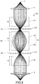
- FIG. 2 illustrates the configuration of the monochromator, 200, associated with the second embodiment.
- Those members of the monochromator 200 which are similar in function with their respective counterparts of the monochromator 100 associated with the first embodiment are indicated by the same reference numerals as in FIG. 1 and a detailed description thereof is omitted.
- the second Wien filter 20 and the third Wien filter 30 are fabricated integrally as a single fifth Wien filter 50. That is, the monochromator 200 is equipped with three stages of Wien filters.
- the fifth Wien filter 50 is disposed between the first Wien filter 10 and the fourth Wien filter 40.
- the length of the fifth Wien filter 50 taken along the optical axis of the electrodes and magnetic polepieces is twice the length of the first Wien filter 10 taken along the optical axis of the electrodes and magnetic polepieces.
- the distance between the first Wien filter 10 and the fifth Wien filter 50 is equal to the distance between the fifth Wien filter 50 and the fourth Wien filter 40.
- the distance between the first Wien filter 10 and the first energy-selecting slit 60 is equal to the distance between the first energy-selecting slit 60 and the fifth Wien filter 50.
- the distance between the fifth Wien filter 50 and the second energy-selecting slit 62 is equal to the distance between the second energy-selecting slit 62 and the fourth Wien filter 40.
- the second Wien filter 20 and the third Wien filter 30 are fabricated integrally. Therefore, the third plane of symmetry M3 is located at the center of the fifth Wien filter 50 as taken along the optical axis.
- the operation of the monochromator 200 is next described by referring to the electron ray diagram of FIG. 2 .
- the first, fifth, and fourth Wien filters 10, 50, and 40 are so operated that the first, second, third, and fourth Wien filters 10, 20, 30, 40 produce the same electromagnetic field.
- Electron rays emitted from the electron source 3 are collimated by the first electrostatic lens 4 and spectrally dispersed by the first Wien filter 10. As a result, a spectrum corresponding to the velocity distribution among the electron rays is created on the first energy-selecting slit 60.
- the electron rays which are uniform in velocity are passed through the first energy-selecting slit 60. Consequently, the electron rays are monochromatized.
- the electron rays passed through the first energy-selecting slit 60 have a finite energy width corresponding to the width of the slit 60.
- the electron rays passed through the first energy-selecting slit 60 are spectrally dispersed by the fifth Wien filter 50. As a result, a spectrum corresponding to the distribution of velocity of the electron rays is created on the second energy-selecting slit 62. The electron rays passed through this slit 62 enter the fourth Wien filter 40.
- the electron rays are collimated, and positional dispersion and angular dispersion are canceled out.
- the trajectories of electron rays having different energies coincide in the fourth Wien filter 40, thus canceling positional dispersion and angular dispersion.
- the electron rays passed through the fourth Wien filter 40 are converged into one point by the second electrostatic lens 8.
- positional dispersion and angular dispersion of the electron rays are canceled out and so energy dispersion is canceled out at and around the focal plane for the electron rays passed through the monochromator 200.
- the virtual electron source assumes a circular form.
- the second Wien filter 20 and the third Wien filter 30 are fabricated integrally.
- the monochromator 200 can yield advantageous effects similar to those produced by the above-described monochromator 100.
- FIG. 3 illustrates the configuration of the electron microscope, 300, associated with the third embodiment.
- the electron microscope 300 is equipped with the monochromator 100 for monochromatizing electron rays directed at a sample.
- the electron microscope 300 may be equipped with the monochromator 200 in a manner not illustrated.
- the electron microscope 300 includes the electron source 3, an aperture stop 302, the first electrostatic lens 4, the second electrostatic lens 8, an accelerator tube 304, an illumination lens system 306, a sample stage 308, an objective lens 310, a projector lens system 312, a detector 314, as well as the monochromator 100.
- the electron source 3 emits electron rays, for example, by accelerating electrons, which are released from a cathode, by means of an anode.
- the electron source 3 is a well-known electron gun, for example.
- the first electrostatic lens 4 is mounted ahead of (i.e., upstream of) the monochromator 100 and operates to adjust the trajectories of the electron rays ejected from the electron source 3, i.e., the angles of incidence of the electron rays relative to the monochromator 100.
- the monochromator 100 is incorporated in the illumination system of the electron microscope 300.
- the electron rays are monochromatized by the monochromator 100.
- the second electrostatic lens 8 is mounted behind the monochromator 100 and operates to adjust the trajectories of the electron rays impinging on the sample.
- the electron rays monochromatized by the monochromator 100 are accelerated by the accelerator tube 304 and directed at a sample held on the sample stage 308 through the illumination lens system 306.
- the illumination lens system 306 is made up of a plurality of condenser lenses.
- the electron rays transmitted through the sample are brought to a focus by the objective lens 310.
- the focused electron rays are then magnified by the projector lens system 312 and focused onto the detector 314.
- a TEM image focused by the projector lens system 312 is detected by the detector 314.
- the monochromator 100 is placed ahead of (i.e., upstream of) the accelerator tube 304.
- the monochromator 100 may be placed behind the accelerator tube 304.
- the electron microscope 300 being a transmission electron microscope (TEM) is set forth as a charged particle beam system including the monochromator 100.
- the charged particle beam system including the monochromator 100 is not restricted to a transmission electron microscope.
- Examples of the charged particle beam system including the monochromator 100 include, for example, a scanning transmission electron microscope (STEM), a scanning electron microscope (SEM), and a focused ion beam (FIB) system.
- the present invention is not restricted to the above-described embodiments but rather can be modified variously.
- the present invention embraces configurations substantially identical (e.g., in function and method) with the configurations described in any one of the embodiments of the invention.
- the invention embraces configurations described in the embodiments and including portions which have non-essential portions replaced.
- the invention embraces configurations which are similar to the configurations described in the embodiments except that well-known techniques are added.
Landscapes
- Chemical & Material Sciences (AREA)
- Analytical Chemistry (AREA)
- Electron Tubes For Measurement (AREA)
Abstract
Description
- The present invention relates to a monochromator and a charged particle beam system.
- Monochromators are used to achieve higher resolution in electron energy loss spectroscopy (EELS) implemented in transmission electron microscopy (TEM). In a transmission electron microscope, the maximum amount of information achievable by a transmission electron microscope (TEM) image can be improved by monochromatizing the electron rays by means of a monochromator. Also, the morphology of a substance can be imaged and observed at atomic resolution. In scanning transmission electron microscopy (STEM), electronic states of an atomic-scale, microscopic area of a substance can be analyzed by the use of both high-angle annular dark field scanning transmission electron microscopy (HAADF-STEM) and EELS to achieve both atomic-scale spatial resolution and high energy resolution at the same time using a monochromator and an aberration corrector on the illumination side.
- Monochromators of the single Wien filter type and monochromators of the double Wien filter type are known (see, for example, patent document 1).
- With the single Wien filter type, a spectrum is created at the crossover point of the electron rays emerging from the Wien filter. An energy-selecting slit is placed at a plane that is conjugate to the spectrum. The electron rays passed through the energy-selecting slit have an finite energy width corresponding to the slit width. Therefore, the electron source of the electron rays passed through the monochromator has a shape stretched in the direction of energy dispersion. Consequently, in high-resolution STEM imaging, spatial resolution exhibits anisotropy. Also, in high-resolution TEM imaging, a virtual electron source for the electron rays directed at a sample is not circular in shape but is stretched in a given direction. Hence, interference of electron rays has anisotropy.
- In this way, in the single Wien filter type, energy dispersion remains. On the other hand, in the double Wien filter type, energy dispersion can be canceled out at the focal point of the electron rays passed through the monochromator.
- Patent document 1:
JP-A-2001-357809 -
FIG. 4 shows the configuration of a monochromator, 2, of the double Wien filter type. InFIG. 4 , trajectories of electron rays with different energies are indicated by solid and broken lines. - The
monochromator 2 has a Wienfilter 5, an energy-selectingslit 6, and another Wienfilter 7. Anelectrostatic lens 4 is positioned at the entrance of themonochromator 2, while anotherelectrostatic lens 8 is located at the exit of themonochromator 2. - Rays of an electron beam emitted from an
electron source 3 are collimated by theelectrostatic lens 4 and spectrally dispersed by the Wienfilter 5. As a result, a spectrum corresponding to the velocity distribution in the electron beam is created on the energy-selectingslit 6. Thisslit 6 passes the electron rays which are uniform in velocity. Consequently, the electron rays are monochromatized. The electron rays passed through the energy-selectingslit 6 have a finite energy width corresponding to the width of theslit 6. - The electron rays passed through the energy-selecting
slit 6 are collimated by the Wienfilter 7 and converged into one point by theelectrostatic lens 8. Consequently, energy dispersion is canceled out. The rays are achromatized at the focal plane. The virtual electron source for the achromatized electron rays at the focal plane is circular in shape. - It is possible to form STEM images having high, isotropic spatial resolution by using a circular virtual electron source and focusing monochromatized electron rays onto a sample in this way. This allows for analysis, for example, using both HAADF-STEM and EELS in which both high spatial resolution and high energy resolution are achieved at the same time.
- Where a TEM image is generated by irradiating a wide area of a sample with an electron beam, the electron beam interference is made isotropic by the circular virtual electron source. Furthermore, the effects of chromatic aberration are reduced by the monochromatization of the electron beam. This allows for, for example, generation of TEM images having higher resolution.
- In the
monochromator 2 of the double Wien filter type, energy dispersion is canceled out at the focal plane for the electron rays passed through the monochromator as noted above. However, energy dispersion occurs before and after the focal plane because angular dispersion occurs in the electron rays exiting from themonochromator 2. - In particular, in the
monochromator 2, different energies of the electron rays cause the angles of the electron rays relative to the optical axis to be nonuniform. In the example shown inFIG. 4 , the electron rays of different energies are converged into one point by theelectrostatic lens 8 but the trajectories from theelectrostatic lens 8 to the focal plane form nonuniform angles relative to the optical axis. Consequently, angular dispersion occurs. - As also shown in
FIG. 4 , in an angular region A1 close to the optical axis, electron rays having different energies overlap each other and so the electron beam energy is uniform. However, in angular regions A2 remote from the optical axis in the direction of energy dispersion, electron rays having different energies do not overlap and thus the electron beam energy is not uniform. Therefore, energy dispersion occurs before and after the focal plane for the electron rays passed through the monochromator. Accordingly, in a case where a defocused electron beam is made to impinge on a sample, for example, the electron beam does not have uniform energy in the angular regions A2. In consequence, a TEM image generated from the electron rays in the angular regions A2 is blurred. - In this way, in the double Wien filter type monochromator, the electron rays passed through the monochromator experience angular dispersion and, therefore, there is a need for a monochromator capable of reducing angular dispersion.
-
- (1) One aspect of the monochromator associated with the present invention has: a first Wien filter; a second Wien filter placed behind (i.e., downstream of) the first Wien filter; a third Wien filter placed behind the second Wien filter; a fourth Wien filter placed behind the third Wien filter; and at least one energy-selecting slit placed in at least one of a space between the first and second Wien filters and a space between the third and fourth Wien filters. The first and second Wien filters are arranged symmetrically with respect to a first plane of symmetry. The third and fourth Wien filters are arranged symmetrically with respect to a second plane of symmetry. A pair of the first and second Wien filters and a pair of the third and fourth Wien filters are arranged symmetrically with respect to a third plane of symmetry. The first, second, third, and fourth Wien filters produce their respective electromagnetic fields which are identical in sense and strength.
In this monochromator, positional dispersion and angular dispersion of the electron rays can be reduced by the use of the four stages of Wien filters. - (2) One aspect of the charged particle beam system associated with the present invention includes the monochromator as defined in (1) above.
-
-
FIG. 1 is an electron ray diagram illustrating the configuration of a monochromator associated with a first embodiment of the present invention. -
FIG. 2 is an electron ray diagram illustrating the configuration of a monochromator associated with a second embodiment. -
FIG. 3 is a schematic view illustrating the configuration of an electron microscope associated with a third embodiment. -
FIG. 4 is an electron ray diagram illustrating the configuration of a monochromator of the double Wien filter type. - The preferred embodiments of the present invention are hereinafter described in detail with reference to the drawings. It is to be understood that the embodiments described below are not intended to unduly restrict the content of the present invention delineated by the claims and that not all the configurations described below are essential constituent components of the invention.
- A monochromator associated with a first embodiment is first described by referring to
FIG. 1 , which shows the configuration of the monochromator, 100, associated with the first embodiment. InFIG. 1 , trajectories of electron rays having different energies are indicated by solid and broken lines. - As shown in
FIG. 1 , themonochromator 100 includes afirst Wien filter 10, asecond Wien filter 20, athird Wien filter 30, afourth Wien filter 40, a first energy-selectingslit 60, and a second energy-selectingslit 62. In this way, themonochromator 100 is equipped with four stages of Wien filters. Themonochromator 100 is positioned between a firstelectrostatic lens 4 and a secondelectrostatic lens 8. - The
second Wien filter 20 is located behind (i.e., downstream of) thefirst Wien filter 10. Thethird Wien filter 30 is disposed behind thesecond Wien filter 20. Thefourth Wien filter 40 is positioned behind thethird Wien filter 30. That is, the first, second, third, andfourth filters - The
first Wien filter 10 uses electric and magnetic fields which intersect perpendicularly to each other. Thefirst Wien filter 10 produces an electromagnetic field in an electron beam path. Specifically, thefirst Wien filter 10 applies the mutually perpendicularly intersecting electric and magnetic fields to the path of the electron beam traveling along the optical path. Each of thesecond Wien filter 20,third Wien filter 30, andfourth Wien filter 40 is a filter using mutually perpendicular electric and magnetic fields in the same way as thefirst Wien filter 10, and produces an electromagnetic field within the electron beam path. - All of the
first Wien filter 10,second Wien filter 20,third Wien filter 30, andfourth Wien filter 40 produce the same electromagnetic field. That is, the electromagnetic fields produced by the first through fourth Wien filters 10, 20, 30, 40, respectively, are identical in strength and sense. That electromagnetic fields are identical in strength means that their electric fields are identical in strength and their magnetic fields are identical in strength. Also, that electromagnetic fields are identical in sense means that their electric fields are identical in sense and their magnetic fields are identical in sense. - The
first Wien filter 10,second Wien filter 20,third Wien filter 30, andfourth Wien filter 40 have heights H1, H2, H3, and H4, respectively, which are all equal to each other. That is, H1:H2:H3:H4 = 1:1:1:1. The height of a Wien filter can also be referred to as the filter length. - The
first Wien filter 10 and thesecond Wien filter 20 are arranged symmetrically with respect to a first plane of symmetry M1. Thethird Wien filter 30 and thefourth Wien filter 40 are arranged symmetrically with respect to a second plane of symmetry M2. The distance between thefirst Wien filter 10 and thesecond Wien filter 20 is equal to the distance between thethird Wien filter 30 and thefourth Wien filter 40. - A pair of the
first filter 10 andsecond filter 20 and a pair of thethird filter 30 andfourth filter 40 are arranged symmetrically with respect to a third plane of symmetry M3. The distance between thesecond Wien filter 20 and the third plane of symmetry M3 is equal to the distance between the third plane of symmetry M3 and thethird Wien filter 30. - The first energy-selecting
slit 60 is disposed between thefirst Wien filter 10 and thesecond Wien filter 20 and placed in the first plane of symmetry M1. The first energy-selectingslit 60 has a finite width. - The second energy-selecting
slit 62 is disposed between thethird Wien filter 30 and thefourth Wien filter 40 and positioned in the second plane of symmetry M2. The second energy-selectingslit 62 has a finite width. - The first
electrostatic lens 4 is mounted at the entrance of themonochromator 100 and located ahead of thefirst Wien filter 10. The firstelectrostatic lens 4 operates to collimate the electron rays emitted from theelectron source 3. That is, the electron rays emanating from theelectron source 3 are collimated by the action of the firstelectrostatic lens 4. - The second
electrostatic lens 8 is mounted at the exit of themonochromator 100 and located behind thefourth Wien filter 40. The secondelectrostatic lens 8 operates to converge the electron rays passed through thefourth Wien filter 40. - The operation of the
monochromator 100 is next described by referring to the electron ray diagram ofFIG. 1 . - In the
monochromator 100, the first through fourth Wien filters 10, 20, 30, 40 are operated such that the same electromagnetic field is produced by these Wien filters 10, 20, 30, 40. - The electron rays emitted from the
electron source 3 are collimated by the firstelectrostatic lens 4 and spectrally dispersed by thefirst Wien filter 10. As a result, a spectrum corresponding to the velocity distribution among the electron rays is created on the first energy-selectingslit 60. The electron rays which have been made uniform in velocity are passed through the first energy-selectingslit 60. Consequently, the electron rays are monochromatized. The electron rays emerging from theslit 60 have a finite energy width corresponding to the width of the first energy-selectingslit 60. - The electron rays passed through the first energy-selecting
slit 60 are collimated by thesecond Wien filter 20 and spectrally dispersed by thethird Wien filter 30. As a result, a spectrum corresponding to the distribution of velocity among the electron rays is formed on the second energy-selectingslit 62. The electron rays passed through theslit 62 enter thefourth Wien filter 40. - In the
fourth Wien filter 40, the electron rays are collimated. Also, positional dispersion and angular dispersion are canceled out. As shown inFIG. 1 , the trajectories of the electron rays having different energies agree in thefourth Wien filter 40, whereby the positional dispersion and angular dispersion are canceled out. - The electron rays passed through the
fourth Wien filter 40 are converged into one point by the secondelectrostatic lens 8. In themonochromator 100, positional dispersion and angular dispersion of the electron rays are canceled out and, therefore, the energy dispersion is nullified at and around the focal plane for the electron rays passed through themonochromator 100. In consequence, the virtual electron source becomes circular in shape. - Positional dispersion means that in a monochromator, electron rays are different in position due to their different energies. Angular dispersion means that in a monochromator, the electron rays form different angles relative to the optical axis due to their different energies.
- In the example shown in
FIG. 1 , both first energy-selectingslit 60 and second energy-selectingslit 62 are used. Alternatively, either only the first energy-selectingslit 60 or only the second energy-selectingslit 62 may be used because the first andsecond slits - The
monochromator 100 includes thefirst Wien filter 10, thesecond Wien filter 20, thethird Wien filter 30, and thefourth Wien filter 40. The first through fourth Wien filters 10, 20, 30, 40 produce electromagnetic fields which are identical in sense and strength. Therefore, in themonochromator 100, positional dispersion and angular dispersion in the electron rays can be reduced as described previously. As a result, where TEM imaging is done, for example, such that a defocused electron beam is directed at a sample, the energies of the rays of the beam can be made uniform. Furthermore, where STEM imaging is done using an electron beam not focused greatly, electron scattering can be achieved by the use of the electron beam having a uniform energy distribution. This can eliminate the anisotropy of chromatic aberration in - In the double Wien
filter type monochromator 2 shown inFIG. 4 , for example, an electron beam having a uniform energy distribution can be extracted by inserting an aperture stop for limiting the angle of the beam such that electron rays lying in the angular region A1 pass through the aperture stop. - However, where TEM imaging is done in such a way that the electron beam is defocused (i.e., spread in cross section) and that a wide area of a sample is irradiated with the electron beam, if an aperture stop is inserted, the strength of the electron beam impinging on the sample will decrease. In TEM imaging using a monochromator, monochromatization of the electron beam decreases the current dose. Eventually, this will lead to a severe shortage of the strength of the electron beam.
- In STEM imaging where an electron beam is focused and scanned over a sample to image a sample, the cross section of the electron beam is demagnified to an atomic scale by the use of condenser lenses. This also results in an increase in the angular magnification of the electron beam. Therefore, the angular dispersion incurred in the
monochromator 2 is enlarged. Also, the angular region A1 is enlarged. Consequently, in STEM imaging where the electron beam is converged greatly, it is easy to obtain an electron beam having a uniform energy distribution. - However, where analysis is performed using a technique such as electron energy loss spectroscopy (EELS) or energy dispersive x-ray spectroscopy (EDS), the electron beam may not be converged strongly. In such a case, the angular region A1 shrinks and the electron beam hitting the sample suffers from angular dispersion. As a result, the energy distribution of the electron beam scattered over a wide angle, which is detected by HAADF-STEM, becomes nonuniform. Anisotropy may be induced in the resolution by the effects of chromatic aberration.
- In the
monochromator 100, the angular distribution in the electron beam can be reduced by the four stages of Wien filters as described above and so the above-described problems do not occur. - In the foregoing description, the
monochromator 100 monochromatizes the electron beam. Themonochromator 100 may monochromatize a charged particle beam such as an ion beam other than an electron beam. - A monochromator associated with a second embodiment is next described by referring to
FIG. 2 , which illustrates the configuration of the monochromator, 200, associated with the second embodiment. Those members of themonochromator 200 which are similar in function with their respective counterparts of themonochromator 100 associated with the first embodiment are indicated by the same reference numerals as inFIG. 1 and a detailed description thereof is omitted. - As shown in
FIG. 2 , in themonochromator 200, thesecond Wien filter 20 and thethird Wien filter 30 are fabricated integrally as a singlefifth Wien filter 50. That is, themonochromator 200 is equipped with three stages of Wien filters. Thefifth Wien filter 50 is disposed between thefirst Wien filter 10 and thefourth Wien filter 40. - The
fifth Wien filter 50 has a height H5 which is equal to the sum of the height H2 of thesecond Wien filter 20 and the height H3 of thethird Wien filter 30. That is, the heights H1, H5, and H4 of the first, fifth, and fourth Wien filters 10, 50, and 40, respectively, have the relationship: H1:H5:H4 = 1:2:1. For example, the length of thefifth Wien filter 50 taken along the optical axis of the electrodes and magnetic polepieces is twice the length of thefirst Wien filter 10 taken along the optical axis of the electrodes and magnetic polepieces. - The distance between the
first Wien filter 10 and thefifth Wien filter 50 is equal to the distance between thefifth Wien filter 50 and thefourth Wien filter 40. - The distance between the
first Wien filter 10 and the first energy-selectingslit 60 is equal to the distance between the first energy-selectingslit 60 and thefifth Wien filter 50. The distance between thefifth Wien filter 50 and the second energy-selectingslit 62 is equal to the distance between the second energy-selectingslit 62 and thefourth Wien filter 40. - In the
monochromator 200, thesecond Wien filter 20 and thethird Wien filter 30 are fabricated integrally. Therefore, the third plane of symmetry M3 is located at the center of thefifth Wien filter 50 as taken along the optical axis. - The operation of the
monochromator 200 is next described by referring to the electron ray diagram ofFIG. 2 . - In the
monochromator 200, the first, fifth, and fourth Wien filters 10, 50, and 40 are so operated that the first, second, third, and fourth Wien filters 10, 20, 30, 40 produce the same electromagnetic field. - Electron rays emitted from the
electron source 3 are collimated by the firstelectrostatic lens 4 and spectrally dispersed by thefirst Wien filter 10. As a result, a spectrum corresponding to the velocity distribution among the electron rays is created on the first energy-selectingslit 60. The electron rays which are uniform in velocity are passed through the first energy-selectingslit 60. Consequently, the electron rays are monochromatized. The electron rays passed through the first energy-selectingslit 60 have a finite energy width corresponding to the width of theslit 60. - The electron rays passed through the first energy-selecting
slit 60 are spectrally dispersed by thefifth Wien filter 50. As a result, a spectrum corresponding to the distribution of velocity of the electron rays is created on the second energy-selectingslit 62. The electron rays passed through thisslit 62 enter thefourth Wien filter 40. - In the
fourth Wien filter 40, the electron rays are collimated, and positional dispersion and angular dispersion are canceled out. As shown inFIG. 2 , the trajectories of electron rays having different energies coincide in thefourth Wien filter 40, thus canceling positional dispersion and angular dispersion. - The electron rays passed through the
fourth Wien filter 40 are converged into one point by the secondelectrostatic lens 8. In themonochromator 200, positional dispersion and angular dispersion of the electron rays are canceled out and so energy dispersion is canceled out at and around the focal plane for the electron rays passed through themonochromator 200. As a result, the virtual electron source assumes a circular form. - In the
monochromator 200, thesecond Wien filter 20 and thethird Wien filter 30 are fabricated integrally. Themonochromator 200 can yield advantageous effects similar to those produced by the above-describedmonochromator 100. - An electron microscope associated with a third embodiment is next described by referring to
FIG. 3 , which illustrates the configuration of the electron microscope, 300, associated with the third embodiment. - The
electron microscope 300 is equipped with themonochromator 100 for monochromatizing electron rays directed at a sample. Alternatively, theelectron microscope 300 may be equipped with themonochromator 200 in a manner not illustrated. - As shown in
FIG. 3 , theelectron microscope 300 includes theelectron source 3, anaperture stop 302, the firstelectrostatic lens 4, the secondelectrostatic lens 8, anaccelerator tube 304, anillumination lens system 306, asample stage 308, anobjective lens 310, aprojector lens system 312, adetector 314, as well as themonochromator 100. - The
electron source 3 emits electron rays, for example, by accelerating electrons, which are released from a cathode, by means of an anode. Theelectron source 3 is a well-known electron gun, for example. - The first
electrostatic lens 4 is mounted ahead of (i.e., upstream of) themonochromator 100 and operates to adjust the trajectories of the electron rays ejected from theelectron source 3, i.e., the angles of incidence of the electron rays relative to themonochromator 100. - The
monochromator 100 is incorporated in the illumination system of theelectron microscope 300. The electron rays are monochromatized by themonochromator 100. - The second
electrostatic lens 8 is mounted behind themonochromator 100 and operates to adjust the trajectories of the electron rays impinging on the sample. - The electron rays monochromatized by the
monochromator 100 are accelerated by theaccelerator tube 304 and directed at a sample held on thesample stage 308 through theillumination lens system 306. Theillumination lens system 306 is made up of a plurality of condenser lenses. - The electron rays transmitted through the sample are brought to a focus by the
objective lens 310. The focused electron rays are then magnified by theprojector lens system 312 and focused onto thedetector 314. A TEM image focused by theprojector lens system 312 is detected by thedetector 314. - In the example shown in
FIG. 3 , themonochromator 100 is placed ahead of (i.e., upstream of) theaccelerator tube 304. Alternatively, themonochromator 100 may be placed behind theaccelerator tube 304. - In the foregoing description, the
electron microscope 300 being a transmission electron microscope (TEM) is set forth as a charged particle beam system including themonochromator 100. The charged particle beam system including themonochromator 100 is not restricted to a transmission electron microscope. Examples of the charged particle beam system including themonochromator 100 include, for example, a scanning transmission electron microscope (STEM), a scanning electron microscope (SEM), and a focused ion beam (FIB) system. - It is to be understood that the present invention is not restricted to the above-described embodiments but rather can be modified variously. For example, the present invention embraces configurations substantially identical (e.g., in function and method) with the configurations described in any one of the embodiments of the invention. Furthermore, the invention embraces configurations described in the embodiments and including portions which have non-essential portions replaced. Further, the invention embraces configurations which are similar to the configurations described in the embodiments except that well-known techniques are added.
Claims (4)
- A monochromator comprising:a first Wien filter;a second Wien filter placed behind the first Wien filter;a third Wien filter placed behind the second Wien filter;a fourth Wien filter placed behind the third Wien filter; andat least one energy-selecting slit placed in at least one of a space between the first and second Wien filters and a space between the third and fourth Wien filters;wherein the first and second Wien filters are arranged symmetrically with respect to a first plane of symmetry;wherein the third and fourth Wien filters are arranged symmetrically with respect to a second plane of symmetry;wherein a pair of said first and second Wien filters and a pair of said third and fourth Wien filters are arranged symmetrically with respect to a third plane of symmetry; andwherein the first, second, third, and fourth Wien filters produce their respective electromagnetic fields which are identical in sense and strength.
- A monochromator as set forth in claim 1, wherein said at least one energy-selecting slit is two in number, and wherein one of these two energy-selecting slits is placed in said first plane of symmetry while the other is placed in said second plane of symmetry.
- A monochromator as set forth in any one of claims 1 and 2, wherein said second Wien filter and said third Wien filter are fabricated integrally.
- A charged particle beam system including a monochromator as set forth in any one of claims 1 to 3.
Applications Claiming Priority (1)
| Application Number | Priority Date | Filing Date | Title |
|---|---|---|---|
| JP2019116967A JP6914993B2 (en) | 2019-06-25 | 2019-06-25 | Monochromator and charged particle beam device |
Publications (2)
| Publication Number | Publication Date |
|---|---|
| EP3758042A1 true EP3758042A1 (en) | 2020-12-30 |
| EP3758042B1 EP3758042B1 (en) | 2021-09-08 |
Family
ID=71120118
Family Applications (1)
| Application Number | Title | Priority Date | Filing Date |
|---|---|---|---|
| EP20181438.1A Active EP3758042B1 (en) | 2019-06-25 | 2020-06-22 | Monochromator and charged particle beam system |
Country Status (3)
| Country | Link |
|---|---|
| US (1) | US11094498B2 (en) |
| EP (1) | EP3758042B1 (en) |
| JP (1) | JP6914993B2 (en) |
Families Citing this family (1)
| Publication number | Priority date | Publication date | Assignee | Title |
|---|---|---|---|---|
| GB202410707D0 (en) * | 2024-07-22 | 2024-09-04 | Nu Instruments Ltd | Beam filter arrangements in mass spectrometers |
Citations (3)
| Publication number | Priority date | Publication date | Assignee | Title |
|---|---|---|---|---|
| US4755685A (en) * | 1985-10-16 | 1988-07-05 | Hitachi, Ltd. | Ion micro beam apparatus |
| JP2001357809A (en) | 2000-04-10 | 2001-12-26 | Jeol Ltd | Monochromator for electron beam |
| US20020104966A1 (en) * | 2000-12-12 | 2002-08-08 | Erich Plies | Monochromator for charged particles |
Family Cites Families (5)
| Publication number | Priority date | Publication date | Assignee | Title |
|---|---|---|---|---|
| JPH01264149A (en) * | 1988-04-15 | 1989-10-20 | Hitachi Ltd | Charged particle beam applied device |
| US5097126A (en) * | 1990-09-25 | 1992-03-17 | Gatan, Inc. | High resolution electron energy loss spectrometer |
| US6495826B2 (en) | 2000-04-10 | 2002-12-17 | Jeol, Ltd. | Monochrometer for electron beam |
| JP5836171B2 (en) * | 2012-03-21 | 2015-12-24 | 日本電子株式会社 | Adjustment method of transmission electron microscope |
| KR101815850B1 (en) * | 2016-03-23 | 2018-01-30 | 한국표준과학연구원 | Monochromator and Charged Particle Beam Instrument comprising the same |
-
2019
- 2019-06-25 JP JP2019116967A patent/JP6914993B2/en active Active
-
2020
- 2020-06-22 EP EP20181438.1A patent/EP3758042B1/en active Active
- 2020-06-24 US US16/910,270 patent/US11094498B2/en active Active
Patent Citations (3)
| Publication number | Priority date | Publication date | Assignee | Title |
|---|---|---|---|---|
| US4755685A (en) * | 1985-10-16 | 1988-07-05 | Hitachi, Ltd. | Ion micro beam apparatus |
| JP2001357809A (en) | 2000-04-10 | 2001-12-26 | Jeol Ltd | Monochromator for electron beam |
| US20020104966A1 (en) * | 2000-12-12 | 2002-08-08 | Erich Plies | Monochromator for charged particles |
Non-Patent Citations (1)
| Title |
|---|
| KAWANAMI Y ET AL: "FOCUSED ION BEAM SYSTEM WITH A FOUR STAGE E X B MASS FILTER", NUCLEAR INSTRUMENTS & METHODS IN PHYSICS RESEARCH. SECTION B: BEAM INTERACTIONS WITH MATERIALS AND ATOMS, ELSEVIER BV, NL, vol. B37/38, no. 2, 2 February 1989 (1989-02-02), pages 240 - 243, XP000045234, ISSN: 0168-583X, DOI: 10.1016/0168-583X(89)90177-8 * |
Also Published As
| Publication number | Publication date |
|---|---|
| EP3758042B1 (en) | 2021-09-08 |
| JP2021005442A (en) | 2021-01-14 |
| JP6914993B2 (en) | 2021-08-04 |
| US11094498B2 (en) | 2021-08-17 |
| US20200411273A1 (en) | 2020-12-31 |
Similar Documents
| Publication | Publication Date | Title |
|---|---|---|
| JP5710061B2 (en) | High-throughput SEM tool | |
| US9153413B2 (en) | Multi-beam scanning electron beam device and methods of using the same | |
| US7915584B2 (en) | TEM with aberration corrector and phase plate | |
| CN102064074B (en) | For the adjuster of the axial aberration of particle-optical lens | |
| JP4368381B2 (en) | Charged particle beam energy width reduction system for charged particle beam system | |
| US8183526B1 (en) | Mirror monochromator for charged particle beam apparatus | |
| US10971326B2 (en) | Multi-electron-beam imaging apparatus with improved performance | |
| NL2012618A (en) | Scanning particle microscope having an energy selective detector system. | |
| US20250125115A1 (en) | Multi-beam system and multi-beam forming unit with reduced sensitivity to secondary radiation | |
| US8884245B2 (en) | Corrector for the correction of chromatic aberrations in a particle-optical apparatus | |
| US9595417B2 (en) | High resolution charged particle beam device and method of operating the same | |
| US7679054B2 (en) | Double stage charged particle beam energy width reduction system for charged particle beam system | |
| EP3758042B1 (en) | Monochromator and charged particle beam system | |
| JP4343951B2 (en) | Single stage charged particle beam energy width reduction system for charged particle beam system | |
| Hawkes | Aberration correction | |
| US20110139978A1 (en) | Charged particle beam device, method of operating a charged particle beam device | |
| EP3799108A1 (en) | Input lens and electron spectrometer | |
| JP3696827B2 (en) | Energy filter | |
| US11276549B1 (en) | Compact arrangement for aberration correction of electron lenses | |
| JP2006278069A (en) | Wien filter type energy analyzer and emission electron microscope | |
| KR20250162319A (en) | Split-column acceleration tube scanning electron microscope | |
| JP2022074749A (en) | X-ray detector, and charged particle beam device | |
| CN118800636A (en) | Techniques for electron energy loss spectroscopy at high energy losses |
Legal Events
| Date | Code | Title | Description |
|---|---|---|---|
| PUAI | Public reference made under article 153(3) epc to a published international application that has entered the european phase |
Free format text: ORIGINAL CODE: 0009012 |
|
| STAA | Information on the status of an ep patent application or granted ep patent |
Free format text: STATUS: THE APPLICATION HAS BEEN PUBLISHED |
|
| AK | Designated contracting states |
Kind code of ref document: A1 Designated state(s): AL AT BE BG CH CY CZ DE DK EE ES FI FR GB GR HR HU IE IS IT LI LT LU LV MC MK MT NL NO PL PT RO RS SE SI SK SM TR |
|
| AX | Request for extension of the european patent |
Extension state: BA ME |
|
| STAA | Information on the status of an ep patent application or granted ep patent |
Free format text: STATUS: REQUEST FOR EXAMINATION WAS MADE |
|
| 17P | Request for examination filed |
Effective date: 20201229 |
|
| RBV | Designated contracting states (corrected) |
Designated state(s): AL AT BE BG CH CY CZ DE DK EE ES FI FR GB GR HR HU IE IS IT LI LT LU LV MC MK MT NL NO PL PT RO RS SE SI SK SM TR |
|
| GRAP | Despatch of communication of intention to grant a patent |
Free format text: ORIGINAL CODE: EPIDOSNIGR1 |
|
| STAA | Information on the status of an ep patent application or granted ep patent |
Free format text: STATUS: GRANT OF PATENT IS INTENDED |
|
| INTG | Intention to grant announced |
Effective date: 20210518 |
|
| RAP3 | Party data changed (applicant data changed or rights of an application transferred) |
Owner name: JEOL LTD. |
|
| GRAS | Grant fee paid |
Free format text: ORIGINAL CODE: EPIDOSNIGR3 |
|
| GRAA | (expected) grant |
Free format text: ORIGINAL CODE: 0009210 |
|
| STAA | Information on the status of an ep patent application or granted ep patent |
Free format text: STATUS: THE PATENT HAS BEEN GRANTED |
|
| AK | Designated contracting states |
Kind code of ref document: B1 Designated state(s): AL AT BE BG CH CY CZ DE DK EE ES FI FR GB GR HR HU IE IS IT LI LT LU LV MC MK MT NL NO PL PT RO RS SE SI SK SM TR |
|
| REG | Reference to a national code |
Ref country code: GB Ref legal event code: FG4D |
|
| REG | Reference to a national code |
Ref country code: CH Ref legal event code: EP Ref country code: AT Ref legal event code: REF Ref document number: 1429333 Country of ref document: AT Kind code of ref document: T Effective date: 20210915 |
|
| REG | Reference to a national code |
Ref country code: DE Ref legal event code: R096 Ref document number: 602020000522 Country of ref document: DE |
|
| REG | Reference to a national code |
Ref country code: IE Ref legal event code: FG4D |
|
| REG | Reference to a national code |
Ref country code: LT Ref legal event code: MG9D |
|
| REG | Reference to a national code |
Ref country code: NL Ref legal event code: MP Effective date: 20210908 |
|
| PG25 | Lapsed in a contracting state [announced via postgrant information from national office to epo] |
Ref country code: BG Free format text: LAPSE BECAUSE OF FAILURE TO SUBMIT A TRANSLATION OF THE DESCRIPTION OR TO PAY THE FEE WITHIN THE PRESCRIBED TIME-LIMIT Effective date: 20211208 Ref country code: LT Free format text: LAPSE BECAUSE OF FAILURE TO SUBMIT A TRANSLATION OF THE DESCRIPTION OR TO PAY THE FEE WITHIN THE PRESCRIBED TIME-LIMIT Effective date: 20210908 Ref country code: NO Free format text: LAPSE BECAUSE OF FAILURE TO SUBMIT A TRANSLATION OF THE DESCRIPTION OR TO PAY THE FEE WITHIN THE PRESCRIBED TIME-LIMIT Effective date: 20211208 Ref country code: HR Free format text: LAPSE BECAUSE OF FAILURE TO SUBMIT A TRANSLATION OF THE DESCRIPTION OR TO PAY THE FEE WITHIN THE PRESCRIBED TIME-LIMIT Effective date: 20210908 Ref country code: FI Free format text: LAPSE BECAUSE OF FAILURE TO SUBMIT A TRANSLATION OF THE DESCRIPTION OR TO PAY THE FEE WITHIN THE PRESCRIBED TIME-LIMIT Effective date: 20210908 Ref country code: ES Free format text: LAPSE BECAUSE OF FAILURE TO SUBMIT A TRANSLATION OF THE DESCRIPTION OR TO PAY THE FEE WITHIN THE PRESCRIBED TIME-LIMIT Effective date: 20210908 Ref country code: SE Free format text: LAPSE BECAUSE OF FAILURE TO SUBMIT A TRANSLATION OF THE DESCRIPTION OR TO PAY THE FEE WITHIN THE PRESCRIBED TIME-LIMIT Effective date: 20210908 Ref country code: RS Free format text: LAPSE BECAUSE OF FAILURE TO SUBMIT A TRANSLATION OF THE DESCRIPTION OR TO PAY THE FEE WITHIN THE PRESCRIBED TIME-LIMIT Effective date: 20210908 |
|
| REG | Reference to a national code |
Ref country code: AT Ref legal event code: MK05 Ref document number: 1429333 Country of ref document: AT Kind code of ref document: T Effective date: 20210908 |
|
| PG25 | Lapsed in a contracting state [announced via postgrant information from national office to epo] |
Ref country code: LV Free format text: LAPSE BECAUSE OF FAILURE TO SUBMIT A TRANSLATION OF THE DESCRIPTION OR TO PAY THE FEE WITHIN THE PRESCRIBED TIME-LIMIT Effective date: 20210908 Ref country code: GR Free format text: LAPSE BECAUSE OF FAILURE TO SUBMIT A TRANSLATION OF THE DESCRIPTION OR TO PAY THE FEE WITHIN THE PRESCRIBED TIME-LIMIT Effective date: 20211209 |
|
| PG25 | Lapsed in a contracting state [announced via postgrant information from national office to epo] |
Ref country code: AT Free format text: LAPSE BECAUSE OF FAILURE TO SUBMIT A TRANSLATION OF THE DESCRIPTION OR TO PAY THE FEE WITHIN THE PRESCRIBED TIME-LIMIT Effective date: 20210908 |
|
| PG25 | Lapsed in a contracting state [announced via postgrant information from national office to epo] |
Ref country code: IS Free format text: LAPSE BECAUSE OF FAILURE TO SUBMIT A TRANSLATION OF THE DESCRIPTION OR TO PAY THE FEE WITHIN THE PRESCRIBED TIME-LIMIT Effective date: 20220108 Ref country code: SM Free format text: LAPSE BECAUSE OF FAILURE TO SUBMIT A TRANSLATION OF THE DESCRIPTION OR TO PAY THE FEE WITHIN THE PRESCRIBED TIME-LIMIT Effective date: 20210908 Ref country code: SK Free format text: LAPSE BECAUSE OF FAILURE TO SUBMIT A TRANSLATION OF THE DESCRIPTION OR TO PAY THE FEE WITHIN THE PRESCRIBED TIME-LIMIT Effective date: 20210908 Ref country code: RO Free format text: LAPSE BECAUSE OF FAILURE TO SUBMIT A TRANSLATION OF THE DESCRIPTION OR TO PAY THE FEE WITHIN THE PRESCRIBED TIME-LIMIT Effective date: 20210908 Ref country code: PT Free format text: LAPSE BECAUSE OF FAILURE TO SUBMIT A TRANSLATION OF THE DESCRIPTION OR TO PAY THE FEE WITHIN THE PRESCRIBED TIME-LIMIT Effective date: 20220110 Ref country code: PL Free format text: LAPSE BECAUSE OF FAILURE TO SUBMIT A TRANSLATION OF THE DESCRIPTION OR TO PAY THE FEE WITHIN THE PRESCRIBED TIME-LIMIT Effective date: 20210908 Ref country code: NL Free format text: LAPSE BECAUSE OF FAILURE TO SUBMIT A TRANSLATION OF THE DESCRIPTION OR TO PAY THE FEE WITHIN THE PRESCRIBED TIME-LIMIT Effective date: 20210908 Ref country code: EE Free format text: LAPSE BECAUSE OF FAILURE TO SUBMIT A TRANSLATION OF THE DESCRIPTION OR TO PAY THE FEE WITHIN THE PRESCRIBED TIME-LIMIT Effective date: 20210908 Ref country code: CZ Free format text: LAPSE BECAUSE OF FAILURE TO SUBMIT A TRANSLATION OF THE DESCRIPTION OR TO PAY THE FEE WITHIN THE PRESCRIBED TIME-LIMIT Effective date: 20210908 Ref country code: AL Free format text: LAPSE BECAUSE OF FAILURE TO SUBMIT A TRANSLATION OF THE DESCRIPTION OR TO PAY THE FEE WITHIN THE PRESCRIBED TIME-LIMIT Effective date: 20210908 |
|
| REG | Reference to a national code |
Ref country code: DE Ref legal event code: R097 Ref document number: 602020000522 Country of ref document: DE |
|
| PLBE | No opposition filed within time limit |
Free format text: ORIGINAL CODE: 0009261 |
|
| STAA | Information on the status of an ep patent application or granted ep patent |
Free format text: STATUS: NO OPPOSITION FILED WITHIN TIME LIMIT |
|
| PG25 | Lapsed in a contracting state [announced via postgrant information from national office to epo] |
Ref country code: DK Free format text: LAPSE BECAUSE OF FAILURE TO SUBMIT A TRANSLATION OF THE DESCRIPTION OR TO PAY THE FEE WITHIN THE PRESCRIBED TIME-LIMIT Effective date: 20210908 |
|
| 26N | No opposition filed |
Effective date: 20220609 |
|
| PG25 | Lapsed in a contracting state [announced via postgrant information from national office to epo] |
Ref country code: MC Free format text: LAPSE BECAUSE OF FAILURE TO SUBMIT A TRANSLATION OF THE DESCRIPTION OR TO PAY THE FEE WITHIN THE PRESCRIBED TIME-LIMIT Effective date: 20210908 Ref country code: IT Free format text: LAPSE BECAUSE OF FAILURE TO SUBMIT A TRANSLATION OF THE DESCRIPTION OR TO PAY THE FEE WITHIN THE PRESCRIBED TIME-LIMIT Effective date: 20210908 |
|
| REG | Reference to a national code |
Ref country code: BE Ref legal event code: MM Effective date: 20220630 |
|
| PG25 | Lapsed in a contracting state [announced via postgrant information from national office to epo] |
Ref country code: LU Free format text: LAPSE BECAUSE OF NON-PAYMENT OF DUE FEES Effective date: 20220622 Ref country code: IE Free format text: LAPSE BECAUSE OF NON-PAYMENT OF DUE FEES Effective date: 20220622 |
|
| PG25 | Lapsed in a contracting state [announced via postgrant information from national office to epo] |
Ref country code: BE Free format text: LAPSE BECAUSE OF NON-PAYMENT OF DUE FEES Effective date: 20220630 |
|
| REG | Reference to a national code |
Ref country code: CH Ref legal event code: PL |
|
| PG25 | Lapsed in a contracting state [announced via postgrant information from national office to epo] |
Ref country code: MK Free format text: LAPSE BECAUSE OF FAILURE TO SUBMIT A TRANSLATION OF THE DESCRIPTION OR TO PAY THE FEE WITHIN THE PRESCRIBED TIME-LIMIT Effective date: 20210908 Ref country code: CY Free format text: LAPSE BECAUSE OF FAILURE TO SUBMIT A TRANSLATION OF THE DESCRIPTION OR TO PAY THE FEE WITHIN THE PRESCRIBED TIME-LIMIT Effective date: 20210908 Ref country code: CH Free format text: LAPSE BECAUSE OF NON-PAYMENT OF DUE FEES Effective date: 20230630 |
|
| PG25 | Lapsed in a contracting state [announced via postgrant information from national office to epo] |
Ref country code: HU Free format text: LAPSE BECAUSE OF FAILURE TO SUBMIT A TRANSLATION OF THE DESCRIPTION OR TO PAY THE FEE WITHIN THE PRESCRIBED TIME-LIMIT; INVALID AB INITIO Effective date: 20200622 |
|
| PG25 | Lapsed in a contracting state [announced via postgrant information from national office to epo] |
Ref country code: MT Free format text: LAPSE BECAUSE OF FAILURE TO SUBMIT A TRANSLATION OF THE DESCRIPTION OR TO PAY THE FEE WITHIN THE PRESCRIBED TIME-LIMIT Effective date: 20210908 |
|
| PGFP | Annual fee paid to national office [announced via postgrant information from national office to epo] |
Ref country code: DE Payment date: 20250618 Year of fee payment: 6 |
|
| PGFP | Annual fee paid to national office [announced via postgrant information from national office to epo] |
Ref country code: GB Payment date: 20250618 Year of fee payment: 6 |
|
| PGFP | Annual fee paid to national office [announced via postgrant information from national office to epo] |
Ref country code: FR Payment date: 20250626 Year of fee payment: 6 |
|
| PG25 | Lapsed in a contracting state [announced via postgrant information from national office to epo] |
Ref country code: TR Free format text: LAPSE BECAUSE OF FAILURE TO SUBMIT A TRANSLATION OF THE DESCRIPTION OR TO PAY THE FEE WITHIN THE PRESCRIBED TIME-LIMIT Effective date: 20210908 |
|
| PG25 | Lapsed in a contracting state [announced via postgrant information from national office to epo] |
Ref country code: SI Free format text: LAPSE BECAUSE OF FAILURE TO SUBMIT A TRANSLATION OF THE DESCRIPTION OR TO PAY THE FEE WITHIN THE PRESCRIBED TIME-LIMIT Effective date: 20210908 |