EP3757713A1 - Device, method and program for controlling ship body - Google Patents
Device, method and program for controlling ship body Download PDFInfo
- Publication number
- EP3757713A1 EP3757713A1 EP20181370.6A EP20181370A EP3757713A1 EP 3757713 A1 EP3757713 A1 EP 3757713A1 EP 20181370 A EP20181370 A EP 20181370A EP 3757713 A1 EP3757713 A1 EP 3757713A1
- Authority
- EP
- European Patent Office
- Prior art keywords
- ship
- controller
- speed
- automatic
- automatic cruise
- Prior art date
- Legal status (The legal status is an assumption and is not a legal conclusion. Google has not performed a legal analysis and makes no representation as to the accuracy of the status listed.)
- Withdrawn
Links
Images






Classifications
-
- G—PHYSICS
- G05—CONTROLLING; REGULATING
- G05D—SYSTEMS FOR CONTROLLING OR REGULATING NON-ELECTRIC VARIABLES
- G05D1/00—Control of position, course, altitude or attitude of land, water, air or space vehicles, e.g. using automatic pilots
- G05D1/02—Control of position or course in two dimensions
- G05D1/0206—Control of position or course in two dimensions specially adapted to water vehicles
-
- B—PERFORMING OPERATIONS; TRANSPORTING
- B63—SHIPS OR OTHER WATERBORNE VESSELS; RELATED EQUIPMENT
- B63B—SHIPS OR OTHER WATERBORNE VESSELS; EQUIPMENT FOR SHIPPING
- B63B79/00—Monitoring properties or operating parameters of vessels in operation
- B63B79/40—Monitoring properties or operating parameters of vessels in operation for controlling the operation of vessels, e.g. monitoring their speed, routing or maintenance schedules
-
- B—PERFORMING OPERATIONS; TRANSPORTING
- B63—SHIPS OR OTHER WATERBORNE VESSELS; RELATED EQUIPMENT
- B63B—SHIPS OR OTHER WATERBORNE VESSELS; EQUIPMENT FOR SHIPPING
- B63B79/00—Monitoring properties or operating parameters of vessels in operation
- B63B79/10—Monitoring properties or operating parameters of vessels in operation using sensors, e.g. pressure sensors, strain gauges or accelerometers
-
- B—PERFORMING OPERATIONS; TRANSPORTING
- B63—SHIPS OR OTHER WATERBORNE VESSELS; RELATED EQUIPMENT
- B63H—MARINE PROPULSION OR STEERING
- B63H25/00—Steering; Slowing-down otherwise than by use of propulsive elements; Dynamic anchoring, i.e. positioning vessels by means of main or auxiliary propulsive elements
- B63H25/02—Initiating means for steering, for slowing down, otherwise than by use of propulsive elements, or for dynamic anchoring
- B63H25/04—Initiating means for steering, for slowing down, otherwise than by use of propulsive elements, or for dynamic anchoring automatic, e.g. reacting to compass
- B63H2025/045—Initiating means for steering, for slowing down, otherwise than by use of propulsive elements, or for dynamic anchoring automatic, e.g. reacting to compass making use of satellite radio beacon positioning systems, e.g. the Global Positioning System [GPS]
Definitions
- the ship body control device comprises a user setting interface to set a watch area where a caution is needed when the ship enters into the watch area, and the autopilot controller determines that the condition of canceling the automatic cruise is satisfied when the position of the ship enters into the watch area.
- the user setting interface accepts an operation of a forced termination of the automatic cruise, and the autopilot controller determines that the condition of canceling the automatic cruise is satisfied when the operation of the forced termination is accepted.
- Fig. 1 is a functional block diagram illustrating a configuration of the ship body control device according to this embodiment of the present disclosure.
- the ship body control device 10 may perform various kinds of cruise controls of the ship described below. Note that, below, although the ship speed control is described concretely and description of the rudder angle control is omitted, the rudder angle control may also suitably be performed along the ship speed control.
- a user can set the heading change point WP1, the heading change point WP2, the destination point WPe, and a cruising route (the order of the heading change points through which the ship passes) by using the UI part 30.
- the AP controller 20 may store coordinates of the heading change point WP1, the heading change point WP2, the destination point WPe, and the cruising route which are set by the UI part 30.
- Step S113 If the AP controller 20 detects entering into the destination area (Step S113: YES), it may perform a deceleration and stop control (Step S114).
- the user may generate a return instruction (see the ship 1(tm) in Fig. 4A ).
- the return instruction can be implemented, for example, by the UI part 30 being provided with a portable device capable of performing wireless communications.
- the return instruction may be given to the AP controller 20.
- the AP controller 20 can receive the return instruction wirelessly from a portable device of the user (e.g., a helmsman) who even falls in the water.
- This portable device and the UI part 30 may correspond to a "return accepting part" in the present disclosure.
- the ship body control device 10 can slow down the ship 1 and stop near the returning position Pm. Further, by using configuration of this embodiment, the safety upon cruising of the ship 1 during the returning may be secured.
- the AP controller 20 may cancel the automatic cruise at the automatic ship speed Va to perform the deceleration control (Step S204).
- the AP controller 20 may perform the cruise control at the returning ship speed Vtmr after the deceleration control (Step S205).
- the AP controller 20 may sequentially acquire the position coordinates of the ship from the sensor 40 during the cruise on the returning route RTr (Step S206).
- the display part 31 may display a display image 311 of a normal autopilot function, a target object detection image 330, and a selected contents notifying window 340 on a display screen 310.
- the display part 31 may display the target object detection image 330 and the selected contents notifying window 340 so as to overlap them with the display image 311 of the normal autopilot function.
- the display part 31 may change the display from the display image 311 of the normal autopilot function to the selected contents notifying window 340.
- the target object detection image 330 is displayed simultaneously, it may be better because the position of the target object can be seen.
- Fig. 8 is a flowchart of the control during the detection of the risky target object.
- the AP controller 20 may sequentially perform the target object detection (Step S302). Until the AP controller 20 detects the risky target object (Step S303: NO), it may continue the automatic cruise. If the AP controller 20 detects the risky target object (Step S303: YES), it may output the deceleration control instruction Dvt to perform the deceleration control (Step S304).
- the AP controller 20 may generate a control instruction for maintaining the speed Vd during the deceleration, and output it to the propelling force controller 50. If the operational input part 32 detects an operation of the ship speed resuming button 3423, the AP controller 20 may generate a control instruction for resuming the automatic ship speed Va, and output it to the propelling force controller 50.
- the selected contents notifying window 340H may have a notifying window 341H, a stop button 3421, a deceleration maintaining button 3422, and a ship speed resuming button 3423.
- the AP controller 20 may display a notification of the deceleration start due to the posture change and wording which urges a selection of operation, on the notifying window 341D. If the operational input part 32 detects an operation of the stop button 3421, the AP controller 20 may generate a stop control instruction of the propelling force, and output it to the propelling force controller 50.
- Step S601 the AP controller 20 may become in a state waiting for accepting the operational input. Until the AP controller 20 accepts the operational input (Step S602: NO), it may continue the automatic cruise. If the AP controller 20 accepts the operational input (Step S602: YES), it may analyze the contents of the operational input (Step S603).
- Fig. 17 is a flowchart of the setting control for the ship speed and the rotating speed.
- a simplified ship speed name may be indicated in each of the plurality of ship speed name display marks 371, 372, 373, and 374.
- the AP controller 20 may detect the selected ship speed name display mark, and set the automatic ship speed Va as the ship speed associated with the detected ship speed name display mark.
- Remarks corresponding to the ship speed name associated with each of the plurality of remark display windows 3712, 3722, 3732, and 3742 may be indicated in the corresponding the remark display window. For example, a situation where the corresponding automatic ship speed is used may be indicated in the remark display window. Note that other contents may also be indicated in the remark display window.
- the remark display windows 3712, 3722, 3732, and 3742 may be acceptable of an operation.
- the remark display windows 3712, 3722, 3732, and 3742 can be edited by this operation.
- a start time setting of the deceleration may be indicated in the start time display window 382.
- a start time of the deceleration is, for example, a lapsed time from the start time of the automatic cruise.
- the start time display window 382 may be acceptable of an operation.
- the start time display window 382 can be edited by this operation.
- the AP controller 20 may have a timer function, and start the deceleration control by using the start time setting.
Landscapes
- Engineering & Computer Science (AREA)
- Chemical & Material Sciences (AREA)
- Combustion & Propulsion (AREA)
- Mechanical Engineering (AREA)
- Ocean & Marine Engineering (AREA)
- Radar, Positioning & Navigation (AREA)
- Aviation & Aerospace Engineering (AREA)
- Remote Sensing (AREA)
- Physics & Mathematics (AREA)
- General Physics & Mathematics (AREA)
- Automation & Control Theory (AREA)
- Traffic Control Systems (AREA)
- Control Of Vehicle Engines Or Engines For Specific Uses (AREA)
Abstract
Description
- The present disclosure relates to a technology of a control of a ship body, such as a cruising speed of the ship body.
-
JP2004-142538A - However, in the conventional ship body control, when performing an automatic cruise control, it is difficult to perform a safe control according to an external state.
- Therefore, one purpose of the present disclosure is to perform a safe ship body control according to an external state, including an automatic cruise.
- According to one aspect of the present disclosure, a ship body control device is provided, which includes a sensor, a propelling force controller, and an autopilot controller. The sensor measures a speed of a ship. The propelling force controller controls a propelling force of the ship. The autopilot controller outputs an instruction to reduce the propelling force to the propelling force controller, when a condition of canceling an automatic cruise in which the speed of the ship matches with an automatic ship speed setting is satisfied.
- With this configuration, when the automatic cruise is canceled, the propelling force is reduced at least temporarily and the ship speed reduces.
- The sensor measures a position of the ship, and the autopilot controller determines that the condition of canceling the automatic cruise is satisfied when the position of the ship enters into a heading change area determined based on a heading change point during the automatic cruise.
- The autopilot controller determines that the condition of canceling the automatic cruise is satisfied when the position of the ship enters into a destination area determined based on a destination point during the automatic cruise.
- The ship body control device incluses a user setting interface to set a watch area where a caution is needed when the ship enters into the watch area, and the autopilot controller determines that the condition of canceling the automatic cruise is satisfied when the position of the ship enters into the watch area.
- The user setting interface accepts an instruction of a return of the ship to a returning position, and the autopilot controller determines that the condition of canceling the automatic cruise is satisfied when the instruction of the return is accepted.
- The autopilot controller performs a return control to the returning position in which the ship speed is slower than the automatic ship speed setting after the automatic cruise is canceled.
- The sensor detects a target object around the ship, and the autopilot controller determines that the condition of canceling the automatic cruise is satisfied when the target object is detected in a risky area around the ship.
- The sensor measures a posture of the ship, and the autopilot controller determines that the condition of canceling the automatic cruise is satisfied when the posture of the ship is a risky posture during a cruise.
- The user setting interface accepts an operation of a forced termination of the automatic cruise, and the autopilot controller determines that the condition of canceling the automatic cruise is satisfied when the operation of the forced termination is accepted.
- The user setting interface accepts an operation for the speed of the ship, and the autopilot controller notifies the contents of a selection of the speed of the ship for the control after the propelling force is reduced when the condition of canceling the automatic cruise is satisfied, and performs a control selected by the user setting interface.
- The autopilot controller stores a time to a deceleration start at which the speed of the ship is reduced, and determines that the condition of canceling the automatic cruise is satisfied when the time to the deceleration start is lapsed.
- The autopilot controller estimates an estimated time of arrival to a destination point of a route set by the automatic cruise.
- The autopilot controller determines a heading change area and a deceleration rate of the automatic cruise based on the automatic ship speed setting, a heading change angle, and a heading change rate.
- The autopilot controller determines a destination area according to a destination point of the automatic cruise based on the automatic ship speed setting.
- The autopilot controller re-estimates and updates the estimated time of arrival when the autopilot controller outputs the instruction to reduce the propelling force from the automatic cruise setting.
- According to another aspect of the present disclosure, a method of controlling a ship body of a ship includes: 1) measuring a speed of the ship, 2) controlling a propelling force of the ship, and 3) reducing the propelling force, when a condition of canceling an automatic cruise in which the speed of the ship matches with an automatic ship speed setting is satisfied.
- According to another aspect of the present disclosure, a non-transitory computer-readable recording medium stores a program causing an autopilot controller of a ship body control device of a ship to execute processing, and the autopilot controller controls operation of the device (10). The processing includes: 1) measuring a speed of the ship, 2) controlling a propelling force of the ship, and 3) reducing the propelling force, when a condition of canceling an automatic cruise in which the speed of the ship matches with an automatic ship speed setting is satisfied.
- According to the present disclosure, a safe ship body control according to an external state including an automatic cruise can be performed.
- The present disclosure is illustrated by way of example and not by way of limitation in the figures of the accompanying drawings, in which like reference numerals indicate like elements and in which:
-
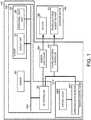
Fig. 1 is a functional block diagram illustrating a configuration of a ship body control device according to one embodiment of the present disclosure; -
Fig. 2 is a view illustrating an outline of a ship body control during an auto cruising mode; -
Fig. 3 is a flowchart of the control during the auto cruising mode; -
Figs. 4A and 4B are views illustrating an outline of a ship body control during a returning mode; -
Fig. 5 is a flowchart of the control during the returning mode; -
Figs. 6A and 6B are views illustrating an outline of a ship body control during a risk detection; -
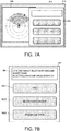
Fig. 7A is a view illustrating one display example of a display part, andFig. 7B is a view illustrating one display example of the contents of selection; -
Fig. 8 is a flowchart of a control during a detection of a risky target object; -
Fig. 9 is a flowchart of a ship speed control according to the contents of an operational input; -
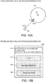
Fig. 10A is a view illustrating an outline of a ship body control during a watch mode, andFig. 10B is a view illustrating one display example of the contents of selection during the watch mode; -
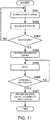
Fig. 11 is a flowchart of a control during an entering into a watch area; -
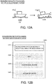
Fig. 12A is a view illustrating an outline of a ship body control during a detection of a posture change, andFig. 12B is a view illustrating one display example of the contents of selection during the detection of the posture change; -
Fig. 13 is a flowchart of a control during the detection of the posture change; -
Fig. 14A is a view illustrating one display example during an automatic cruise, andFig. 14B is a view illustrating one example of an operation accepting window; -
Fig. 15 is a flowchart of a control based on an operational input during the automatic cruise; -
Fig. 16 is a view illustrating one example of a simplified setting window for a ship speed and a rotating speed; -
Fig. 17 is a flowchart of a setting control for the ship speed and the rotating speed; -
Fig. 18 is a view illustrating one example of a simplified setting window for an automatic ship speed; -
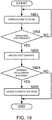
Fig. 19 is a flowchart of a selection setting control for the ship speed; -
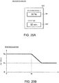
Fig. 20A is a view illustrating one example of a setting window for automatic deceleration, andFig. 20B is a graph illustrating a concept of the automatic deceleration; and -
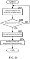
Fig. 21 is a flowchart of an automatic deceleration control. - A ship body control device, a ship body control method, and a ship body control program according to one embodiment of the present disclosure are described with reference to the accompanying drawings.
Fig. 1 is a functional block diagram illustrating a configuration of the ship body control device according to this embodiment of the present disclosure. - As illustrated in
Fig. 1 , a shipbody control device 10 may include amain part 101, aremote control lever 102, a propellingforce controller 50, and arudder controller 60. Themain part 101 may include anAP controller 20, aUI part 30, and asensor 40. Theremote control lever 102 may include acontrol lever 200 and anoperating state detector 201. - The
AP controller 20, theUI part 30, and thesensor 40 may be connected with each other via adata communication network 100 for a ship. TheAP controller 20 may be connected with the propellingforce controller 50, for example, through a communication network (e.g., CAN) for a propelling force. TheAP controller 20 may be connected with therudder controller 60 through an analog voltage or data communications. - A propelling
force generating part 91 may be connected to the propellingforce controller 50. Therudder controller 60 may be connected to arudder 92. The propellingforce generating part 91 and therudder 92 are provided to, for example, anoutboard motor 90. The propellingforce generating part 91 and therudder 92 may be provided to, for example, various kinds of propelling devices, such as an inboard motor and an inboard-outdrive motor. - The
AP controller 20 is comprised of, for example, a processor, such as a CPU, and a memory. The memory may store a program executed by theAP controller 20. The memory may be also used during a calculation by the CPU. TheAP controller 20 may correspond to an "autopilot controller" of the present disclosure. - The
AP controller 20 may perform various kinds of controls (described later). TheAP controller 20 may output instructions according to various kinds of controls to the propellingforce controller 50 and therudder controller 60. - The
UI part 30 may be implemented by a given electronic circuit and electronic components. TheUI part 30 may be a user interface part, and may include adisplay part 31 and anoperational input part 32. Thedisplay part 31 is implemented by, for example, a liquid crystal panel. Theoperational input part 32 may be comprised of a switch and a button. Theoperational input part 32 may be physically independent from thedisplay part 31, or may detect an operation to a screen of thedisplay part 31 where the switch and the button are displayed. TheUI part 30, containing thedisplay part 31 and theoperational input part 32, is collectively described as "a user setting interface" 30. - The
UI part 30 may indicate display data from theAP controller 20 on thedisplay part 31. TheUI part 30 may output the contents of the operation relevant to an autopilot control accepted by theoperational input part 32 to theAP controller 20. That is, theoperational input part 32 may implement a function of an AP interface. - The
sensor 40 may measure data (measurement data) of a speed, a bow direction, etc. of the ship. Note that the present disclosure may be applied to ships which typically travel on water or sea which are referred to as surface ships, and may also be applied to other types of ships including boats, dinghies, watercrafts, and vessels. The ship speed may be used for a control of the propelling force, and the bow direction may be used for a control of the rudder. For example, thesensor 40 is implemented by a positioning sensor utilizing positioning signals of a GNSS (e.g., GPS) and an inertia sensor (e.g., an acceleration sensor). Note that, for the acquisition of the bow direction, thesensor 40 may be, for example, a magnetic sensor. Moreover, according to the control performed by the shipbody control device 10, thesensor 40 may be provided with a function for detecting the state of the ship and the state around the ship, such as a radar and a posture sensor, which detect a target object around the ship. - The
sensor 40 may output the measurement data to theAP controller 20. - The propelling
force controller 50 is implemented by, for example, a given electronic circuit. The propellingforce controller 50 may generate a propelling force control signal according to an instruction from theAP controller 20, and output it to the propellingforce generating part 91. The propellingforce generating part 91 is, for example, an engine for the ship. In this case, the propelling force control signal is, for example, a signal which defines a throttle opening of an engine. - The
rudder controller 60 is implemented by, for example, a given electronic circuit and a physical control mechanism of a rudder angle of a rudder. Therudder controller 60 may determine the rudder angle of therudder 92 according to an instruction from theAP controller 20. - The
control lever 200 of theremote control lever 102 may accept a user's operation for the manual cruise. The operatingstate detector 201 may be implemented by a sensor etc. The operatingstate detector 201 may detect an operating state of thecontrol lever 200. The detection of the operating state by the operatingstate detector 201 may sequentially be performed at a given time interval. The operatingstate detector 201 may output the detected operating state (angle) of the control lever to the propellingforce controller 50. TheAP controller 20 may receive this operating state. - In such a configuration, the ship
body control device 10 may perform various kinds of cruise controls of the ship described below. Note that, below, although the ship speed control is described concretely and description of the rudder angle control is omitted, the rudder angle control may also suitably be performed along the ship speed control. -
Fig. 2 is a view illustrating an outline of the ship body control during an auto cruising mode. As illustrated inFig. 2 , during the auto cruising mode, aship 1 may stop at a destination point WPe via a heading change point WP1 and a heading change point WP2. - A user can set the heading change point WP1, the heading change point WP2, the destination point WPe, and a cruising route (the order of the heading change points through which the ship passes) by using the
UI part 30. TheAP controller 20 may store coordinates of the heading change point WP1, the heading change point WP2, the destination point WPe, and the cruising route which are set by theUI part 30. - Moreover, the user can set a speed (automatic ship speed Va) during cruising straight (cruising straight in setting) in the auto cruising mode by using the
UI part 30. TheAP controller 20 may store the automatic ship speed Va. - When the
UI part 30 accepts the operational input of the automatic cruise from the user, theAP controller 20 may acquire position coordinates of the ship from thesensor 40, and set a route RT01 from a starting position of the automatic cruise (a position of the ship 1(t0) inFig. 2 ) to the heading change point WP1. Note that thesensor 40 may sequentially measure the position coordinates of the ship, and output them to theAP controller 20 even after setting the route. - The
AP controller 20 may give instructions to the propellingforce controller 50 and therudder controller 60 so that theship 1 cruises along the route RT01 at the automatic ship speed Va. According to this control, theship 1 may cruise along the route RT01 at a constant ship speed of the automatic ship speed Va. Note that, here, there may be various kinds of disturbances in the sea, such as waves, current, and wind. For this reason, theship 1 seldom stays on the route RT01. Thus, theAP controller 20 may suitably control the propelling force and the rudder angle so that theship 1 does not deviate largely from the route RT01. Therefore, theship 1 can cruise along the route RT01 at the constant ship speed of the automatic ship speed Va. That is, the automatic ship speed Va is not simply a ship speed at each time point, but may be an average ship speed while the ship cruises on the route RT01. Alternatively, the route RT01 may be divided into a plurality of sections, and the automatic ship speed Va may be an average speed in each section. Note that the following automatic ship speed Va in each route may be similar. - When the
ship 1 cruises at the automatic ship speed Va, it may approach the heading change point WP1 and enter into a heading change area CP1 (see the ship 1(t1d) inFig. 2 ). A radius of the heading change area CP1 may automatically be calculated by theAP controller 20 based on the automatic ship speed Va, a heading change angle ζ1 at the heading change point WP1, and a heading change rate set so that theship 1 can safely change the heading. TheAP controller 20 may detect entering into the heading change area CP1 by using a spatial relationship between the position coordinates of the ship measured by thesensor 40 and the coordinates indicative of the heading change area CP1. - The
AP controller 20 may cancel the control at the automatic ship speed Va, and give a deceleration control instruction Dv1 to the propellingforce controller 50. The propellingforce controller 50 may perform a control for reducing the propelling force produced by the propellingforce generating part 91, according to the deceleration control instruction Dv1. Here, the user can set a rate of deceleration and an amount of deceleration through theUI part 30. Moreover, theAP controller 20 may automatically calculate the deceleration rate and the deceleration amount based on the heading change angle ζ1 set at the heading change point WP1. As illustrated inFig. 2 , the heading change angle ζ1 may be an angle formed by the route RT01 (the route to the heading change point WP1) and a route RT12 (a route from the heading change point WP1 to the heading change point WP2). - The
ship 1 may slow down by this control. Then, theship 1 may cruise inside the heading change area CP1, changing the heading at a decelerated ship speed Vt1 (<Vo). Here, theAP controller 20 may set the ship speed Vt1 and the heading change rate so that the ship approaches the heading change point WP1 safely and as much as possible, and give them to the propellingforce controller 50 and therudder controller 60. - The
ship 1 may cruise while changing the heading in the heading change area CP1 so that the ship goes toward the heading change point WP2, and leave the heading change area CP1 (see the ship 1(t1a) inFig. 2 ). TheAP controller 20 may detect leaving from the heading change area CP1 by using the spatial relationship between the position coordinates of the ship measured by thesensor 40 and the coordinates indicative of the heading change area CP1. - The
AP controller 20 may resume the control at the automatic ship speed Va, and give an acceleration control instruction Av1 to the propellingforce controller 50. Then, theAP controller 20 may give instructions to the propellingforce controller 50 and therudder controller 60 so that the ship cruises along the route RT12 at the automatic ship speed Va. According to this control, theship 1 may cruise along the route RT12 at a constant ship speed of the automatic ship speed Va (see the ship 1(t12) inFig. 2 ). - When the
ship 1 cruises at the automatic ship speed Va, it may approach the heading change point WP2 and then enter into a heading change area CP2 (see the ship 1(t2d) inFig. 2 ). TheAP controller 20 may detect entering into the heading change area CP2 by using the spatial relationship between the position coordinates of the ship measured by thesensor 40 and the coordinates indicative of the heading change area CP2. - The
AP controller 20 may cancel the control at the automatic ship speed Va, and give a deceleration control instruction Dv2 to the propellingforce controller 50. The propellingforce controller 50 may perform a control for reducing the propelling force produced by the propellingforce generating part 91 according to the deceleration control instruction Dv2. As illustrated inFig. 2 , a heading change angle ζ2 may be an angle formed by the route RT12 (a route from the heading change point WP1 to the heading change point WP2) and a route RT2e (a route from the heading change point WP2 to the destination point WPe). - The
ship 1 may slow down by this control. Then, theship 1 may cruise inside the heading change area CP2, while changing the heading at a decelerated ship speed Vt2 (<Vo). Here, theAP controller 20 may set the ship speed Vt2 and a heading change rate so that the ship approaches the heading change point WP2 safely and as much as possible, and it may give them to the propellingforce controller 50 and therudder controller 60. - The
ship 1 may cruise inside the heading change area CP2 while changing the heading toward the destination point WPe, and then leave the heading change area CP2 (see the ship 1(t2a) inFig. 2 ). TheAP controller 20 may detect leaving from the heading change area CP2 by using the spatial relationship between the position coordinates of the ship measured by thesensor 40 and the coordinates indicative of the heading change area CP2. - The
AP controller 20 may resume the control at the automatic ship speed Va, and give an acceleration control instruction Av2 to the propellingforce controller 50. Then, theAP controller 20 may give instructions to the propellingforce controller 50 and therudder controller 60 so that the ship cruises along the route RT2e at the automatic ship speed Va. According to this control, theship 1 may cruise along the route RT2e at a constant ship speed of the automatic ship speed Va (see the ship 1(t2e) inFig. 2 ). - When the
ship 1 cruises at the automatic ship speed Va, it may approach the destination point WPe and then enter into a destination area CPe (see the ship 1(ted) inFig. 2 ). A radius of the destination area CPe may automatically be calculated by theAP controller 20 based on the automatic ship speed Va and a stop distance according to the deceleration rate set so that theship 1 can slow down and stop safely. TheAP controller 20 may detect entering into the destination area CPe by using the spatial relationship between the position coordinates of the ship measured by thesensor 40 and the coordinates indicative of the destination area CPe. - The
AP controller 20 may cancel the control at the automatic ship speed Va, and give a deceleration control instruction Dve to the propellingforce controller 50. Here, theAP controller 20 may set the deceleration control instruction Dve, for example, to suspend the output of the propellingforce generating part 91. Note that, if the safety upon cruising of theship 1 is spoiled by immediately suspending the output of the propellingforce generating part 91, theAP controller 20 may set the deceleration control instruction Dve to suspend the output after the output is dropped. - The propelling
force controller 50 may perform a control for reducing and suspending the propelling force produced by the propellingforce generating part 91 according to the deceleration control instruction Dve. By this control, theship 1 may slow down and then stop at a position as closest to the destination point WPe as possible. - By using this function, while the
ship 1 cruises at the constant automatic ship speed Va, it can pass through near the heading change points WP1 and WP2 which are desired by the user, and then stop at the destination point WPe. Further, by using the configuration of this embodiment, the safety during the heading change and during the final stop may be secured. That is, while the user secures the safety, the auto cruise can be realized in which the ship moves at the desired automatic ship speed Va as much as possible. - Moreover, with this configuration, since the automatic ship speed Va of each route RT is determined, the
AP controller 20 of the shipbody control device 10 can estimate an estimated time of arrival to the destination point WPe at a start of the automatic cruise. In addition, the shipbody control device 10 can display, for example, the estimated time of arrival on thedisplay part 31. Therefore, the user can easily grasp the estimated time of arrival. - Moreover, with this configuration, the
AP controller 20 of the shipbody control device 10 can estimate an elapsed time of the heading change at each heading change point WP. That is, theAP controller 20 of the shipbody control device 10 can again estimate the estimated time of arrival for every heading change point WP and update it with an estimated time of arrival with higher precision. Therefore, the user can easily grasp the higher-precision estimated time of arrival. - Although in the above description there are two heading change points, the number of heading change points is not limited to this and the above-described control can be performed according to the number of heading change points.
- The above-described control is implemented by, for example, the following method (program).
Fig. 3 is a flowchart of the control during an auto cruising mode. - For example, while a manual ship speed control is performed (Step S101), if the automatic cruise at the automatic ship speed Va is set (Step S102: YES), the
AP controller 20 may transit to the auto cruising mode. If the automatic cruise is not set (Step S102: NO), theAP controller 20 may continue the manual ship speed control (Step S101). - If the
AP controller 20 transits to the auto cruising mode, it may then perform the control in which the ship cruises at the constant ship speed of the automatic ship speed Va (Step S 103). TheAP controller 20 may estimate the estimated time of arrival (Step S 131). TheAP controller 20 may calculate the radius and the deceleration rate of the next heading change area (Step S 132). TheAP controller 20 may sequentially acquire the position coordinates of the ship from thesensor 40 during this automatic cruise (Step S104). - Until the
AP controller 20 detects entering into the heading change area during the automatic cruise (Step S105: NO), it may continue the control in which the ship cruises at the constant ship speed of the automatic ship speed Va. - If the
AP controller 20 detects entering into the heading change area (Step S105: YES), it may output the deceleration control instruction Dv (Step S106). In the heading change area, theAP controller 20 may perform a speed control for the heading change (Step S107). TheAP controller 20 may sequentially acquire the position coordinates of the ship from thesensor 40 during the heading change (Step S108). - Until the
AP controller 20 detects leaving from the heading change area (Step S109: NO), it may continue the speed control for the heading change. - If the
AP controller 20 detects leaving from the heading change area (Step S109: YES), it may output the acceleration control instruction Av (Step S110). TheAP controller 20 may resume the control in which the ship cruises at the constant ship speed of the automatic ship speed Va (Step S111). TheAP controller 20 may estimate and update the estimated time of arrival (Step S133). If the next location is the destination point (Step S134: YES), theAP controller 20 may calculate the radius of the destination area and the deceleration rate (Step S135). TheAP controller 20 may sequentially acquire the position coordinates of the ship from thesensor 40 during the automatic cruise (Step S112). - Until the
AP controller 20 detects entering into the destination area during the automatic cruise (Step S113: NO), it may continue the control in which the ship cruises at the constant ship speed of the automatic ship speed Va (it returns to Step S105). - If the
AP controller 20 detects entering into the destination area (Step S113: YES), it may perform a deceleration and stop control (Step S114). -
Figs. 4A and 4B are views illustrating an outline of a ship body control during a returning mode, whereFig. 4A illustrates a case when a return instruction is generated andFig. 4B illustrates a case during the returning control. As illustrated inFigs. 4A and 4B , during the returning mode, when a specific position (a generating position of the return instruction) is instructed, theship 1 may return to the specific position. - As illustrated in
Fig. 4A , while theship 1 cruises at the automatic ship speed Va, the user may generate a return instruction (see the ship 1(tm) inFig. 4A ). The return instruction can be implemented, for example, by theUI part 30 being provided with a portable device capable of performing wireless communications. The return instruction may be given to theAP controller 20. Thus, by using the portable device capable of performing wireless communications, theAP controller 20 can receive the return instruction wirelessly from a portable device of the user (e.g., a helmsman) who even falls in the water. This portable device and theUI part 30 may correspond to a "return accepting part" in the present disclosure. - When the return instruction is received, the
AP controller 20 may determine position coordinates of a returning position Pm based on the position coordinates of the ship from thesensor 40. - When the return instruction is received, the
AP controller 20 may cancel the cruise at the automatic ship speed Va, and output a deceleration control instruction Dvm. Thus, theship 1 may slow down (see the ship 1(tm0) inFig. 4A ). - The
AP controller 20 may acquire the coordinates of the deceleration starting position. TheAP controller 20 may set a returning route RTr as illustrated inFig. 4B based on the coordinates of the deceleration starting position and the coordinates of the returning position Pm. Moreover, theAP controller 20 may set a returning ship speed Vtmr. The returning ship speed Vtmr may be a ship speed during the cruise on the returning route RTr. The returning route RTr and the returning ship speed Vtmr may be set, for example, in consideration of the safety, so that theship 1 can arrive at the returning position Pm earliest. - When the
ship 1 cruises at the returning ship speed Vtmr along the returning route RTr, it may approach the returning position Pm and then enter into a returning area CPm (see the ship 1(tmd) inFig. 4B ). TheAP controller 20 may detect entering into the returning area CPm by using a spatial relationship between the position coordinates of the ship measured by thesensor 40 and the coordinates indicative of the returning area CPm. - The
AP controller 20 may cancel the control at the returning ship speed Vtmr, and give a deceleration control instruction Dvmd to the propellingforce controller 50. Here, theAP controller 20 may set the deceleration control instruction Dvmd so that theship 1 stops at a position in the returning area CPm away from the returning position Pm by a given distance. - The propelling
force controller 50 may perform a control for reducing and stopping the propelling force produced by the propellingforce generating part 91 according to the deceleration control instruction Dvmd. Therefore, theship 1 may stop at the position away from the returning position Pm by the given distance (see the ship 1(tme) inFig. 4B ). - By using this function, if the returning position Pm is set during the automatic cruise at the automatic ship speed Va, the ship
body control device 10 can slow down theship 1 and stop near the returning position Pm. Further, by using configuration of this embodiment, the safety upon cruising of theship 1 during the returning may be secured. - The above-described control is implemented by, for example, the following method (program).
Fig. 5 is a flowchart of the control during the returning mode. - During the automatic cruise at the automatic ship speed Va (Step S201), if a return trigger is received (Step S202: YES), the
AP controller 20 may transit to the returning mode. If theAP controller 20 does not receive the return trigger (Step S202: NO), it may continue the automatic cruise at the automatic ship speed Va. - If the
AP controller 20 transits to the returning mode, it may acquire the position coordinates of the ship at a timing of receiving the return trigger, and set the returning position (Step S203). - The
AP controller 20 may cancel the automatic cruise at the automatic ship speed Va to perform the deceleration control (Step S204). TheAP controller 20 may perform the cruise control at the returning ship speed Vtmr after the deceleration control (Step S205). TheAP controller 20 may sequentially acquire the position coordinates of the ship from thesensor 40 during the cruise on the returning route RTr (Step S206). - Until the
AP controller 20 detects entering into the returning area CPm during the cruise on the returning route RTr (Step S207: NO), it may continue the control in which the ship cruises along the returning route RTr. - If the
AP controller 20 detects entering into the returning area CPm (Step S207: YES), it may perform the deceleration and stop control (Step S208). -
Figs. 6A and 6B are views illustrating an outline of a ship body control during a risk detection.Fig. 6A illustrates a case where a target object is not detected within a risky area, andFig. 6B illustrates a case where the target object is detected within the risky area. When performing the control of the automatic ship speed by the risky detection, thesensor 40 may have a target object detecting function, such as a radar. - The
sensor 40 may detect a target object around theship 1, and output the detection result to theAP controller 20. TheAP controller 20 may determine whether the target object is detected within a risky area ZnD based on the detection result. The risky area ZnD may be set, for example, by a given direction range in the bow direction of theship 1, as illustrated inFigs. 6A and 6B . - As illustrated in
Fig. 6A , if theAP controller 20 does not detect the target object within the risky area ZnD, it may continue the automatic cruise at the automatic ship speed Va. - As illustrated in
Fig. 6B , if theAP controller 20 detects the target object within the risky area ZnD, it may output a deceleration control instruction Dvt. Thus, theship 1 may slow down to a speed Vd. - The
AP controller 20 may output the deceleration control instruction Dvt and the contents of a selection of the control after the deceleration (after the propelling force is reduced) to theUI part 30. TheUI part 30 may display a display image indicative of the contents of the selection on thedisplay part 31. -
Fig. 7A is a view illustrating one display example of the display part, andFig. 7B is a view illustrating one display example of the contents of the selection. - As illustrated in
Fig. 7A , thedisplay part 31 may display adisplay image 311 of a normal autopilot function, a targetobject detection image 330, and a selectedcontents notifying window 340 on adisplay screen 310. Note that, inFig. 7A , thedisplay part 31 may display the targetobject detection image 330 and the selectedcontents notifying window 340 so as to overlap them with thedisplay image 311 of the normal autopilot function. However, thedisplay part 31 may change the display from thedisplay image 311 of the normal autopilot function to the selectedcontents notifying window 340. Here, if the targetobject detection image 330 is displayed simultaneously, it may be better because the position of the target object can be seen. - As illustrated in
Fig. 7B , the selectedcontents notifying window 340 may have a notifyingwindow 341, astop button 3421, adeceleration maintaining button 3422, and a shipspeed resuming button 3423. TheAP controller 20 may display a notification of a deceleration start upon the detection of the risky target object and wording which urges a selection of operation, on the notifyingwindow 341. When theoperational input part 32 detects an operation of thestop button 3421, theAP controller 20 may generate a stop control instruction of the propelling force, and output it to the propellingforce controller 50. If theoperational input part 32 detects an operation of thedeceleration maintaining button 3422, theAP controller 20 may generate a control instruction for maintaining the speed Vd during the deceleration, and output it to the propellingforce controller 50. When theoperational input part 32 detects an operation of the shipspeed resuming button 3423, theAP controller 20 may generate a control instruction for resuming the automatic ship speed Va, and output it to the propellingforce controller 50. - By using this function, the ship
body control device 10 may slow down the ship when the risky target object is detected during the automatic cruise at the automatic ship speed Va, and therefore, the safety upon cruising of theship 1 can be secured. Further, the user can select the ship speed control after the deceleration, and the shipbody control device 10 can realize the ship body control suitable for the situation of the ship by the easy operation of the user. - The above-described control is implemented by, for example, the following method (program).
Fig. 8 is a flowchart of the control during the detection of the risky target object. - During the automatic cruise at the automatic ship speed Va (Step S301), the
AP controller 20 may sequentially perform the target object detection (Step S302). Until theAP controller 20 detects the risky target object (Step S303: NO), it may continue the automatic cruise. If theAP controller 20 detects the risky target object (Step S303: YES), it may output the deceleration control instruction Dvt to perform the deceleration control (Step S304). - The
AP controller 20 may perform the notification of the deceleration control and the notification of the contents of the selection of control after the deceleration, through the UI part 30 (Step S305). Until theAP controller 20 receives the operational input (Step S306: NO), it may continue the notification of the deceleration control and the notification of the contents of the selection of control after the deceleration. - If the
AP controller 20 accepts the operational input (Step S306: YES), it may perform the ship speed control according to the contents of the input (Step S307). -
Fig. 9 is a flowchart of the ship speed control according to the contents of the operational input. If theAP controller 20 accepts the operational input, it may analyze the contents of the input (Step S371). If thestop button 3421 is operated (Step S372: YES), theAP controller 20 may perform the deceleration and stop control (Step S374). If thedeceleration maintaining button 3422 is operated (Step S372: NO and Step S373: YES), theAP controller 20 may perform the control for maintaining the speed Vd during the deceleration (Step S375). If the shipspeed resuming button 3423 is operated (Step S373: NO), theAP controller 20 may resume the automatic ship speed Va to perform the automatic cruise control (Step S376). -
Fig. 10A is a view illustrating an outline of a ship body control during a watch mode, andFig. 10B is a view illustrating one display example of the contents of a selection during the watch mode. - As illustrated in
Fig. 10A , theAP controller 20 may store a watching point Pd and a watch area CPd. Setup of the watching point Pd and the watch area CPd can be performed by, for example, theUI part 30. - The
ship 1 may enter into the watch area CPd during the automatic cruise at the automatic ship speed Va. TheAP controller 20 may detect entering into the watch area CPd based on a relationship between the position coordinates of the ship by thesensor 40 and the position coordinates of the watch area CPd. - When the
AP controller 20 detects that theship 1 enters into the watch area CPd (see the position of the ship 1(tmd) inFig. 10A ), it may output a deceleration control instruction Dvd. Thus, theship 1 may slow down from the automatic ship speed Va to the ship speed in the watch mode. - The
AP controller 20 may output the deceleration control instruction Dvd and the contents of the selection of control after the deceleration (after the propelling force is reduced) to theUI part 30. TheUI part 30 may display a selectedcontents notifying window 340D indicative of the contents of the selection on thedisplay part 31. - As illustrated in
Fig. 10B , the selectedcontents notifying window 340D may have a notifyingwindow 341D, astop button 3421, adeceleration maintaining button 3422, and a shipspeed resuming button 3423. TheAP controller 20 may display a notification of the deceleration start upon the entering into the watch area CPd and wording which urges a selection of operation, on the notifyingwindow 341D. If theoperational input part 32 detects an operation of thestop button 3421, theAP controller 20 may generate a stop control instruction of the propelling force, and output it to the propellingforce controller 50. If theoperational input part 32 detects an operation of thedeceleration maintaining button 3422, theAP controller 20 may generate a control instruction for maintaining the speed Vd during the deceleration, and output it to the propellingforce controller 50. If theoperational input part 32 detects an operation of the shipspeed resuming button 3423, theAP controller 20 may generate a control instruction for resuming the automatic ship speed Va, and output it to the propellingforce controller 50. - By using this function, if the ship
body control device 10 detects entering into the watch area CPd during the automatic cruise at the automatic ship speed Va, it may slow down the ship, and therefore, the safety upon cruising of theship 1 can be secured. Further, the user can select the ship speed control after the deceleration, and the shipbody control device 10 can realize the ship body control suitable for the situation of the ship by the easy operation of the user. - The above-described control is implemented by, for example, the following method (program).
Fig. 11 is a flowchart of the control during the entering into the watch area. - During the automatic cruise at the automatic ship speed Va (Step S401), the
AP controller 20 may sequentially acquire the position coordinates of the ship (Step S402). Until the ship enters into the watch area CPd (Step S403: NO), theAP controller 20 may continue the automatic cruise. If theship 1 enters into the watch area CPd (Step S403: YES), theAP controller 20 may output the deceleration control instruction Dvd to perform the deceleration control (Step S404). - The
AP controller 20 may perform the notification of the deceleration control and the notification of the contents of the selection of control after the deceleration, through the UI part 30 (Step S405). Until theAP controller 20 accepts the operational input (Step S406: NO), it may continue the notification of the deceleration control and the notification of the contents of the selection of control after the deceleration. - If the
AP controller 20 accepts the operational input (Step S406: YES), it may perform the ship speed control according to the contents of the input (Step S407). The ship speed control according to the contents of the input may be similar to that of the flow illustrated inFig. 9 , and therefore, description thereof is omitted. -
Fig. 12A is a view illustrating an outline of a ship body control during a detection of a posture change, andFig. 12B is a view illustrating one display example of the contents of a selection during the detection of the posture change. - When realizing this function, the
sensor 40 may have a function for detecting the posture of theship 1. Thesensor 40 may detect the posture by using positioning signals, or detect the posture by using an inertia sensor. Thesensor 40 may sequentially output the detected posture to theAP controller 20. - During the automatic cruise of the
ship 1 at the automatic ship speed Va, theAP controller 20 may detect a change in the posture based on the posture acquired sequentially. TheAP controller 20 may detect at least a change in a pitch angle as the change in the posture of theship 1. - The
AP controller 20 may store a threshold for an amount of change in the posture. When the amount of change in the posture exceeds the threshold, theAP controller 20 may output a deceleration control instruction Dvh. Thus, theship 1 may slow down from the automatic ship speed Va. - The
AP controller 20 may output the deceleration control instruction Dvh and the contents of the selection of control after the deceleration (after the propelling force is reduced) to theUI part 30. TheUI part 30 may display a selectedcontents notifying window 340H indicative of the contents of the selection on thedisplay part 31. - As illustrated in
Fig. 12B , the selectedcontents notifying window 340H may have a notifyingwindow 341H, astop button 3421, adeceleration maintaining button 3422, and a shipspeed resuming button 3423. TheAP controller 20 may display a notification of the deceleration start due to the posture change and wording which urges a selection of operation, on the notifyingwindow 341D. If theoperational input part 32 detects an operation of thestop button 3421, theAP controller 20 may generate a stop control instruction of the propelling force, and output it to the propellingforce controller 50. If theoperational input part 32 detects an operation of thedeceleration maintaining button 3422, theAP controller 20 may generate a control instruction for maintaining the speed Vd during the deceleration, and output it to the propellingforce controller 50. If theoperational input part 32 detects an operation of the shipspeed resuming button 3423, theAP controller 20 may generate a control instruction for resuming the automatic ship speed Va, and output it to the propellingforce controller 50. - By using this function, when the ship
body control device 10 detects during the automatic cruise at the automatic ship speed Va the risk of cruising increases due to the posture change, it may slow down the ship, and therefore, the safety upon cruising of theship 1 can be secured. Further, the user can select the ship speed control after the deceleration, and shipbody control device 10 can realize the ship body control suitable for the situation of the ship by the easy operation of the user. - The above-described control is implemented by, for example, the following method (program).
Fig. 13 is a flowchart of a control during the detection of the posture change. - During the automatic cruise at the automatic ship speed Va (Step S501), the
AP controller 20 may sequentially acquire the posture of the ship (Step S502). Until theAP controller 20 detects a risky posture (posture change) (Step S503: NO), it may continue the automatic cruise. If theAP controller 20 detects the risky posture (S503: YES), it may output the deceleration control instruction Dvh to perform the deceleration control (Step S504). - The
AP controller 20 may perform the notification of the deceleration control and the notification of the contents of the selection of control after the deceleration, through the UI part 30 (Step S505). Until theAP controller 20 accepts the operational input (Step S506: NO), it may continue the notification of the deceleration control and the notification of the contents of the selection of control after the deceleration. - If the
AP controller 20 accepts the operational input (Step S506: YES), it may perform the ship speed control according to the contents of the input (Step S507). The ship speed control according to the contents of the input may be similar to that of the flow illustrated inFig. 9 , and therefore, description thereof is omitted. -
Fig. 14A is a view illustrating one display example during the automatic cruise, andFig. 14B is a view illustrating one example of an operation accepting window. - As illustrated in
Figs. 14A and 14B , during the automatic cruise, theAP controller 20 may display anotice 3500 and an operationalinput accepting window 350 on thedisplay screen 310. - The
notice 3500 may describe the contents indicative of the automatic cruise at the constant automatic ship speed Va. For example, thenotice 3500 may describe as "SETTING AUTOMATIC CRUISE." - As illustrated in
Figs. 14A and 14B , the operationalinput accepting window 350 may have astop button 351 to accept an operation of a forced termination of the automatic cruise, a reduced-speed cruising button 352, adeceleration button 353, a reduced-speed display window 3520, and a decelerationrate display window 3530. - When the
operational input part 32 detects an operation of thestop button 351, theAP controller 20 may perform a stop control of the propelling force similar to the above embodiments. If theoperational input part 32 detects an operation of the reduced-speed cruising button 352, theAP controller 20 may perform the ship speed control so that the ship cruises at a reduced speed. The reduced speed may be set suitably. The reduced speed setting may be displayed on the reduced-speed display window 3520. If theoperational input part 32 detects an operation of thedeceleration button 353, theAP controller 20 may perform the deceleration control at the deceleration rate setting by using a method similar to the above embodiments. The deceleration rate may be set suitably. The deceleration rate setting may be displayed on the decelerationrate display window 3530. - By using this function, the ship
body control device 10 can easily receive the operational input of a stop, a reduced-speed cruising, and a deceleration from the user through the operationalinput accepting window 350 during the automatic cruise at the automatic ship speed Va. Then, theship 1 can quickly shift to the stop, the reduced-speed cruising, or the deceleration from the automatic cruise according to the operational input. Therefore, the shipbody control device 10 can secure the safety during the automatic cruise. - The above-described control is implemented by, for example, the following method (program).
Fig. 15 is a flowchart of the control based on the operational input during the automatic cruise. - During the automatic cruise at the automatic ship speed Va (Step S601), the
AP controller 20 may become in a state waiting for accepting the operational input. Until theAP controller 20 accepts the operational input (Step S602: NO), it may continue the automatic cruise. If theAP controller 20 accepts the operational input (Step S602: YES), it may analyze the contents of the operational input (Step S603). - If the
AP controller 20 detects a stop (Step S604: YES), it may perform the deceleration and stop control (Step S606). If theAP controller 20 does not detect the stop (Step S604: NO) and detects the reduced-speed cruising (Step S605: YES), it may perform a reduce-speed cruising control (Step S607). If theAP controller 20 does not detect the stop and the reduced-speed cruising (Step S605: NO), it may perform the deceleration control (Step S608). -
Fig. 16 is a view illustrating one example of the simplified setting window for the ship speed and a rotating speed of an engine. As illustrated inFig. 16 , asimplified setting window 360 may be displayed on thedisplay screen 310. Thesimplified setting window 360 may have a shipspeed display window 361, a shipspeed change icon 3611, a ship speed steppingwidth display window 3612, a rotatingspeed display window 362, a rotatingspeed change icon 3621, and a rotating speed steppingwidth display window 3622. - A current ship speed for the automatic cruise (automatic ship speed Va) may be displayed on the ship
speed display window 361. The shipspeed change icon 3611 may have an UP button and a DOWN button. By the UP button, the operational input which increases the automatic ship speed Va may be accepted. By the DOWN button, the operational input which decreases the automatic ship speed Va may be accepted. Here, a stepping width for increase and decrease may be displayed in the ship speed steppingwidth display window 3612. The stepping width may also be adjusted by directly operating the ship speed steppingwidth display window 3612. TheAP controller 20 may perform a control for increasing or decreasing the automatic ship speed Va according to the stepping width. - The rotating speed corresponding to the current ship speed for the automatic cruise (automatic ship speed Va) may be displayed on the rotating
speed display window 362. The rotatingspeed change icon 3621 may have an UP button and a DOWN button. By the UP button, the operational input which increases the rotating speed may be accepted. By the DOWN button, the operational input which decreases the rotating speed may be accepted. Here, a stepping width for increase and decrease may be displayed in the rotating speed steppingwidth display window 3622. The stepping widths may be adjusted by directly operating the rotating speed steppingwidth display window 3622. TheAP controller 20 may perform a control for increasing or decreasing the rotating speed according to the stepping width. - By using this configuration, the user can easily confirm the automatic ship speed and the rotating speed corresponding to the automatic ship speed, and can easily adjust them to a desired speed and a desired rotating speed.
- The above-described control is implemented by, for example, the following method (program).
Fig. 17 is a flowchart of the setting control for the ship speed and the rotating speed. - The
AP controller 20 may be in a waiting state for the operational input (Step S701). Until theAP controller 20 detects the operational input for the setting change (Step S702: NO), it may maintain the operational input waiting state (Step S701). If theAP controller 20 detects the operational input for the setting change (Step S702: YES), it may confirm whether the operational input is a change for the stepping width. If it is the change for the stepping width (Step S703: YES), theAP controller 20 may change the stepping width and then returns to the input waiting state. - If it is not the change for the stepping width (Step S703: NO), the
AP controller 20 may detect whether it is a change for the ship speed. If it is the change for the ship speed (Step S704: YES), theAP controller 20 may perform the control for changing the ship speed (Step S705). If it is not the change for the ship speed (Step S704: NO), i.e., if it is the change for the rotating speed, theAP controller 20 may change the rotating speed (Step S706). -
Fig. 18 is a view illustrating one example of a simplified setting window for the automatic ship speed. As illustrated inFig. 18 , asimplified setting window 370 for the ship speed may have a plurality of ship speed name display marks 371, 372, 373, and 374, a plurality of shipspeed display windows remark display windows simplified setting window 370 for the ship speed may be displayed on thedisplay screen 310. - The ship speed
name display mark 371, the shipspeed display window 3711, and theremark display window 3712 may be associated with each other. The ship speedname display mark 372, the shipspeed display window 3721, and theremark display window 3722 may be associated with each other. The ship speedname display mark 373, the shipspeed display window 3731, and theremark display window 3732 may be associated with each other. The ship speedname display mark 374, the shipspeed display window 3741, and theremark display window 3742 may be associated with each other. - A simplified ship speed name may be indicated in each of the plurality of ship speed name display marks 371, 372, 373, and 374. The
AP controller 20 may detect the selected ship speed name display mark, and set the automatic ship speed Va as the ship speed associated with the detected ship speed name display mark. - A ship speed setting (automatic ship speed) corresponding to the ship speed name associated with each of the plurality of ship
speed display windows speed display windows speed display windows Fig. 16 and edit the ship speed in the window. - Remarks corresponding to the ship speed name associated with each of the plurality of
remark display windows remark display windows remark display windows - By using this configuration, the user can set the plurality of automatic ship speeds. The user can easily select the plurality of automatic ship speed according to the situation.
- The above-described control is implemented by, for example, the following method (program).
Fig. 19 is a flowchart of the selection setting control for the ship speed. Note that, below, although the automatic ship speed is changed during the automatic cruise, it may also be carried out at the start of the automatic cruise. - During the state of the automatic cruise (Step S801), until the
AP controller 20 detects the operational input (Step S802: NO), it may continue the control so that the automatic cruise at the current automatic ship speed is maintained. If theAP controller 20 detects the operational input (Step S802: YES), it may analyze the contents of the input (Step S803). - If a new automatic ship speed accepted by the operational input differs from the current automatic ship speed (Step S804: YES), the
AP controller 20 may perform the control for changing the automatic ship speed (Step S805). If the new automatic ship speed accepted by the operational input is the same as the current automatic ship speed (Step S804: NO), theAP controller 20 may continue the control so that the automatic cruise at the current automatic ship speed is maintained. -
Fig. 20A is a view illustrating one example of a setting window for the automatic deceleration, andFig. 20B illustrates a graph illustrating a concept of the automatic deceleration. As illustrated inFig. 20A , an automaticdeceleration setting window 380 may have a decelerationrate display window 381 and a starttime display window 382. The automaticdeceleration setting window 380 may be displayed on thedisplay screen 310. - A deceleration rate setting may be indicated in the deceleration
rate display window 381. The decelerationrate display window 381 may be acceptable of an operation. The decelerationrate display window 381 can be edited by this operation. TheAP controller 20 may perform the deceleration control by using the deceleration rate setting. - A start time setting of the deceleration may be indicated in the start
time display window 382. A start time of the deceleration is, for example, a lapsed time from the start time of the automatic cruise. The starttime display window 382 may be acceptable of an operation. The starttime display window 382 can be edited by this operation. TheAP controller 20 may have a timer function, and start the deceleration control by using the start time setting. - By this configuration, the ship
body control device 10 may decelerate theship 1 after a given period of time, even if the ship is under the automatic cruise. By this deceleration, the user may become easier to grasp the situation outside theship 1, and therefore, the safety of the cruising may improve. - The above-described control is implemented by, for example, the following method (program).
Fig. 21 is a flowchart of the automatic deceleration control. - The
AP controller 20 may control the ship speed at a constant ship speed (automatic ship speed) during the automatic cruise (Step S901). TheAP controller 20 may count time, and until the start time setting (deceleration start time) (Step S902: NO), it may continue the control so that the automatic cruise at the current automatic ship speed is maintained. If it becomes the start time (deceleration start time) (Step S902: YES), theAP controller 20 may perform the deceleration control (Step S903). Then, theAP controller 20 may perform the control for maintaining the speed after the deceleration (decelerated speed) (Step S904). - Note that the functions described above may be suitably combined. The ship
body control device 10 can demonstrate operation and effects according to each of the combinations. -
- 1:
- Ship
- 10:
- Ship Body Control Device
- 20:
- AP controller
- 30:
- UI Part (User Setting Interface)
- 31:
- Display Part
- 32:
- Operational Input Part
- 40:
- Sensor
- 50:
- Propelling Force Controller
- 60:
- Rudder Controller
- 90:
- Outboard Motor
- 91:
- Propelling Force Generating Part
- 92:
- Rudder
- 100:
- Data Communication Network
- 102:
- Remote Control Lever
- 200:
- Control Lever
- 201:
- Operating State Detector
- 310:
- Display Screen
- 311:
- Display Image
- 330:
- Target Object Detection Image
- 340, 340D, 340H:
- Selected Content Notifying Window
- 341, 341D, 341H:
- Notifying Window
- 350:
- Window
- 351:
- Stop Button
- 352:
- Reduced-speed Cruising Button
- 353:
- Deceleration Button
- 360:
- Simplified Setting Window
- 361:
- Ship Speed Display Window
- 362:
- Rotating Speed Display Window
- 370:
- Simplified Setting Window
- 371, 372, 373, 374:
- Ship Speed Name Display Mark
- 380:
- Setting Window
- 381:
- Deceleration Rate Display Window
- 382:
- Start Time Display Window
- 3421:
- Stop Button
- 3422:
- Deceleration Maintaining Button
- 3423:
- Ship Speed Resuming Button
- 3500:
- Notice
- 3520:
- Reduced-speed Display Window
- 3530:
- Deceleration Rate Display Window
- 3611:
- Ship Speed Change Icon
- 3612:
- Width Display Window
- 3621:
- Rotating Speed Change Icon
- 3622:
- Width Display Window
- 3711, 3721, 3731, 3741:
- Ship Speed Display Window
- 3712, 3722, 3732, 3742:
- Remark Display Window
Claims (15)
- A ship body control device (10), comprising:a sensor (40) configured to measure a speed of a ship (1);a propelling force controller (50) configured to control a propelling force of the ship (1); andan autopilot controller (20) configured to output an instruction to reduce the propelling force to the propelling force controller (50) when a condition of canceling an automatic cruise in which the speed of the ship (1) matches with an automatic ship speed setting is satisfied.
- The ship body control device (10) of claim 1, wherein the sensor (40) measures a position of the ship (1), and
wherein the autopilot controller (20) determines that the condition of canceling the automatic cruise is satisfied when the position of the ship (1) enters into a heading change area (CP1, CP2) determined based on a heading change point (WP1, WP2) during the automatic cruise. - The ship body control device (10) of claim 2, wherein the autopilot controller (20) determines that the condition of canceling the automatic cruise is satisfied when the position of the ship (1) enters into a destination area (CPe) determined based on a destination point (WPe) during the automatic cruise.
- The ship body control device (10) of claim 2 or 3, comprising a user setting interface (30) configured to set a watch area (CPd) where a caution is needed when the ship (1) enters into the watch area (CPd),
wherein the autopilot controller (20) determines that the condition of canceling the automatic cruise is satisfied when the position of the ship (1) enters into the watch area (CPd). - The ship body control device (10) of any one of claims 1 to 4, comprising a user setting interface (30) configured to accept an instruction of a return of the ship (1) to a returning position (Pm),
wherein the autopilot controller (20) determines that the condition of canceling the automatic cruise is satisfied when the instruction of the return is accepted. - The ship body control device (10) of claim 5, wherein the autopilot controller (20) performs a return control to the returning position (Pm) in which the ship speed is slower than the automatic ship speed setting after the automatic cruise is canceled.
- The ship body control device (10) of any one of claims 1 to 6, wherein the sensor (40) detects a target object around the ship (1), and
wherein the autopilot controller (20) determines that the condition of canceling the automatic cruise is satisfied when the target object is detected in a risky area (ZnD) around the ship (1). - The ship body control device (10) of any one of claims 1 to 7, wherein the sensor (40) measures a posture of the ship (1), and
wherein the autopilot controller (20) determines that the condition of canceling the automatic cruise is satisfied when the posture of the ship (1) is a risky posture during a cruise. - The ship body control device (10) of any one of claims 1 to 8, wherein the user setting interface (30) is further configured to accept an operation of a forced termination of the automatic cruise,
wherein the autopilot controller (20) determines that the condition of canceling the automatic cruise is satisfied when the operation of the forced termination is accepted. - The ship body control device (10) of claim 4, 7, 8, or 9, wherein the user setting interface (30) is further configured to accept an operation for the speed of the ship (1),
wherein the autopilot controller (20) notifies the contents of a selection of the speed of the ship (1) for the control after the propelling force is reduced when the condition of canceling the automatic cruise is satisfied, and performs a control selected by the user setting interface (30). - The ship body control device (10) of any one of claims 1 to 10,
wherein the autopilot controller (20) stores a time to a deceleration start at which the speed of the ship (1) is reduced, and determines that the condition of canceling the automatic cruise is satisfied when the time to the deceleration start is lapsed. - The ship body control device (10) of any one of claims 1 to 11,
wherein the autopilot controller (20) determines a heading change area (CP1, CP2) and a deceleration rate of the automatic cruise based on the automatic ship speed setting, a heading change angle, and a heading change rate. - The ship body control device (10) of any one of claims 1 to 12,
wherein the autopilot controller (20) determines a destination area (CPe) according to a destination point (WPe) of the automatic cruise based on the automatic ship speed setting. - A method of controlling a ship body of a ship (1), comprising:measuring a speed of the ship (1);controlling a propelling force of the ship (1); andreducing the propelling force when a condition of canceling an automatic cruise in which the speed of the ship (1) matches with an automatic ship speed setting is satisfied.
- A non-transitory computer-readable recording medium storing a program causing an autopilot controller (20) of a ship body control device (10) of a ship (1) to execute processing, the autopilot controller (20) configured to control operation of the device (10), the processing comprising:measuring a speed of the ship (1);controlling a propelling force of the ship (1); andreducing the propelling force when a condition of canceling an automatic cruise in which the speed of the ship (1) matches with an automatic ship speed setting is satisfied.
Applications Claiming Priority (1)
| Application Number | Priority Date | Filing Date | Title |
|---|---|---|---|
| JP2019122022A JP7261105B2 (en) | 2019-06-28 | 2019-06-28 | Hull control device, hull control method, and hull control program |
Publications (1)
| Publication Number | Publication Date |
|---|---|
| EP3757713A1 true EP3757713A1 (en) | 2020-12-30 |
Family
ID=71120076
Family Applications (1)
| Application Number | Title | Priority Date | Filing Date |
|---|---|---|---|
| EP20181370.6A Withdrawn EP3757713A1 (en) | 2019-06-28 | 2020-06-22 | Device, method and program for controlling ship body |
Country Status (3)
| Country | Link |
|---|---|
| US (1) | US11873067B2 (en) |
| EP (1) | EP3757713A1 (en) |
| JP (1) | JP7261105B2 (en) |
Families Citing this family (8)
| Publication number | Priority date | Publication date | Assignee | Title |
|---|---|---|---|---|
| US11987339B1 (en) * | 2019-12-26 | 2024-05-21 | Yamaha Hatsudoki Kabushiki Kaisha | Steering control system of marine vessel, marine vessel and steering control method of marine vessel |
| JP2023023442A (en) * | 2021-08-05 | 2023-02-16 | ナブテスコ株式会社 | Main machine control device, control method for main machine control device, and control program for main machine control device |
| JP7676282B2 (en) * | 2021-09-29 | 2025-05-14 | 日本発條株式会社 | Ship, ship control device, ship control method and program |
| CN114962043B (en) * | 2021-12-16 | 2023-08-15 | 中国船舶集团有限公司第七一一研究所 | Speed regulation control device for diesel engine and ship |
| JP2023112442A (en) * | 2022-02-01 | 2023-08-14 | 日本発條株式会社 | system |
| US12461495B2 (en) * | 2022-05-17 | 2025-11-04 | Furuno Electric Co., Ltd. | Disturbance estimating apparatus, method, and computer program |
| US12405610B1 (en) * | 2022-09-06 | 2025-09-02 | Brunswick Corporation | Marine propulsion system and method for wake control |
| JP7716158B1 (en) * | 2025-05-08 | 2025-07-31 | 株式会社エイトノット | Ship control device, ship control method, and program |
Citations (8)
| Publication number | Priority date | Publication date | Assignee | Title |
|---|---|---|---|---|
| US5268844A (en) * | 1989-03-06 | 1993-12-07 | Carver Christopher S | Electronic digital position and navigational plotter |
| JP2004142538A (en) | 2002-10-23 | 2004-05-20 | Yamaha Marine Co Ltd | Ship propulsion control device |
| EP2246765A1 (en) * | 2008-02-19 | 2010-11-03 | Juan Mariano Bendito Vallori | Evasive autopilot system for vessels |
| EP3173324A1 (en) * | 2015-11-25 | 2017-05-31 | Yamaha Hatsudoki Kabushiki Kaisha | Watercraft control method and watercraft control system |
| EP3214523A1 (en) * | 2016-03-01 | 2017-09-06 | Brunswick Corporation | Station keeping and waypoint tracking method and system |
| US20170365175A1 (en) * | 2016-06-20 | 2017-12-21 | Navico Holding As | Watercraft navigation safety system |
| WO2018228670A1 (en) * | 2017-06-13 | 2018-12-20 | Cpac Systems Ab | Method for determining a speed profile for a marine vessel |
| US20190039708A1 (en) * | 2017-08-02 | 2019-02-07 | Steering Solutions Ip Holding Corporation | Marine electric power steering autopilot system |
Family Cites Families (40)
| Publication number | Priority date | Publication date | Assignee | Title |
|---|---|---|---|---|
| JPS5899198U (en) * | 1981-12-28 | 1983-07-06 | 株式会社小松製作所 | Ship automatic rescue equipment |
| JP2964304B2 (en) * | 1995-01-26 | 1999-10-18 | 三井造船株式会社 | Ship route control method and apparatus |
| JP3267516B2 (en) | 1996-10-09 | 2002-03-18 | 日立造船株式会社 | Directional linear movement control equipment for ships |
| JP2004034805A (en) * | 2002-07-02 | 2004-02-05 | Mitsubishi Heavy Ind Ltd | Course display terminal, course evaluation device, and course determining method |
| JP2004142537A (en) | 2002-10-23 | 2004-05-20 | Yamaha Marine Co Ltd | Steering control device of vessel |
| JP2007509792A (en) | 2003-10-28 | 2007-04-19 | エイムブリッジ・ピーティーワイ・リミテッド | Control method and control system for controllable pitch sailing propeller |
| JP4666152B2 (en) | 2005-07-20 | 2011-04-06 | トヨタ自動車株式会社 | Ship maneuvering device |
| JP2007314084A (en) | 2006-05-26 | 2007-12-06 | Yamaha Marine Co Ltd | Operation control device of hydroplane |
| JP4791340B2 (en) | 2006-12-22 | 2011-10-12 | ヤマハ発動機株式会社 | Ship propulsion device control device, cruise support system using the same, and vessel |
| WO2008157459A2 (en) | 2007-06-14 | 2008-12-24 | The Regents Of The University Of Michigan | Methods and systems for identifying molecular pathway elements |
| JP4047369B1 (en) * | 2007-07-17 | 2008-02-13 | 国土交通省国土技術政策総合研究所長 | Ship motion estimation method and system |
| JP4933487B2 (en) | 2008-05-21 | 2012-05-16 | 旭洋造船株式会社 | Fuel efficient transport ship |
| JP5008747B2 (en) | 2010-05-13 | 2012-08-22 | 三菱電機株式会社 | Ship cruise control system |
| US8943988B1 (en) | 2010-11-05 | 2015-02-03 | Enovation Controls, Llc | Dual rudder watercraft steering control system for enhanced maneuverability |
| JP5932362B2 (en) | 2012-01-25 | 2016-06-08 | マロール株式会社 | Hull Control Device, Hull Control Program, and Hull Control Method |
| JP5957695B2 (en) | 2012-07-26 | 2016-07-27 | 古野電気株式会社 | MOBILE BODY CONTROL DEVICE, HULLE CONTROL DEVICE, SHIP, MOBILE BODY CONTROL METHOD, AND MOBILE BODY CONTROL PROGRAM |
| KR101434228B1 (en) | 2012-12-20 | 2014-08-27 | 임선우 | Auto sailing method of yacht by fuzzy reasoning |
| US10747226B2 (en) | 2013-01-31 | 2020-08-18 | Flir Systems, Inc. | Adaptive autopilot control systems and methods |
| US9377780B1 (en) * | 2013-03-14 | 2016-06-28 | Brunswick Corporation | Systems and methods for determining a heading value of a marine vessel |
| JP2015066979A (en) * | 2013-09-26 | 2015-04-13 | ヤマハ発動機株式会社 | Display system for marine vessel and small marine vessel with the same |
| US10137972B2 (en) | 2014-07-28 | 2018-11-27 | Furuno Electric Co., Ltd. | Vessel characteristic estimation device and automatic steering device |
| US10183733B2 (en) | 2014-12-22 | 2019-01-22 | Furuno Electric Co., Ltd. | Program, method and device for controlling movable body |
| WO2016104031A1 (en) | 2014-12-22 | 2016-06-30 | 古野電気株式会社 | Moving body control device, moving body control method, and moving body control program |
| EP3241086B1 (en) | 2014-12-31 | 2024-01-10 | Teledyne Flir, LLC | Autopilot control system |
| JP6632803B2 (en) * | 2015-02-06 | 2020-01-22 | 古野電気株式会社 | Hull control device and hull control method |
| JP2016182877A (en) * | 2015-03-26 | 2016-10-20 | ヤマハ発動機株式会社 | Ship acceleration control system |
| JP2017088119A (en) | 2015-11-17 | 2017-05-25 | ヤマハ発動機株式会社 | Ship maneuvering control method, and ship maneuvering control system |
| JP2017088111A (en) | 2015-11-17 | 2017-05-25 | ヤマハ発動機株式会社 | Ship maneuvering control method and ship maneuvering control system |
| AU2017218906B2 (en) | 2016-02-10 | 2021-06-24 | Marine Canada Acquisition Inc. | System and method for positioning a marine vessel |
| JP2017178242A (en) | 2016-03-31 | 2017-10-05 | 株式会社 神崎高級工機製作所 | Maneuvering system, and ship |
| US10167798B1 (en) * | 2016-10-14 | 2019-01-01 | Brunswick Corporation | Method and system for controlling acceleration of a marine vessel |
| KR20180044087A (en) | 2016-10-21 | 2018-05-02 | 대우조선해양 주식회사 | Dynamic positioning system and dynamic positioning corresponding to fault of gyro sensor method using the same |
| US10836459B2 (en) | 2016-11-17 | 2020-11-17 | Cccc First Harbor Engineering Co., Ltd. | Self-propelled integrated ship for transporting and installing immersed tubes of underwater tunnel and construction process |
| US11188080B2 (en) | 2016-12-02 | 2021-11-30 | Yamaha Hatsudoki Kabushiki Kaisha | Boat and control method for same |
| JP2018192976A (en) | 2017-05-19 | 2018-12-06 | スズキ株式会社 | Control device of outboard engine |
| US10723431B1 (en) * | 2017-09-25 | 2020-07-28 | Brunswick Corporation | Systems and methods for controlling vessel speed when transitioning from launch to cruise |
| TWI645145B (en) | 2018-02-14 | 2018-12-21 | 國立臺灣海洋大學 | Chasing the Japanese system and chasing the Japanese |
| CN109116838B (en) | 2018-04-13 | 2021-11-23 | 上海海事大学 | Automatic berthing auxiliary control method for small ship |
| JP7263150B2 (en) | 2019-06-27 | 2023-04-24 | 古野電気株式会社 | Hull control device, hull control method, and hull control program |
| JP7544470B2 (en) | 2019-09-13 | 2024-09-03 | 古野電気株式会社 | Hull control device, hull control method, and hull control program |
-
2019
- 2019-06-28 JP JP2019122022A patent/JP7261105B2/en active Active
-
2020
- 2020-06-22 EP EP20181370.6A patent/EP3757713A1/en not_active Withdrawn
- 2020-06-23 US US16/909,978 patent/US11873067B2/en active Active
Patent Citations (8)
| Publication number | Priority date | Publication date | Assignee | Title |
|---|---|---|---|---|
| US5268844A (en) * | 1989-03-06 | 1993-12-07 | Carver Christopher S | Electronic digital position and navigational plotter |
| JP2004142538A (en) | 2002-10-23 | 2004-05-20 | Yamaha Marine Co Ltd | Ship propulsion control device |
| EP2246765A1 (en) * | 2008-02-19 | 2010-11-03 | Juan Mariano Bendito Vallori | Evasive autopilot system for vessels |
| EP3173324A1 (en) * | 2015-11-25 | 2017-05-31 | Yamaha Hatsudoki Kabushiki Kaisha | Watercraft control method and watercraft control system |
| EP3214523A1 (en) * | 2016-03-01 | 2017-09-06 | Brunswick Corporation | Station keeping and waypoint tracking method and system |
| US20170365175A1 (en) * | 2016-06-20 | 2017-12-21 | Navico Holding As | Watercraft navigation safety system |
| WO2018228670A1 (en) * | 2017-06-13 | 2018-12-20 | Cpac Systems Ab | Method for determining a speed profile for a marine vessel |
| US20190039708A1 (en) * | 2017-08-02 | 2019-02-07 | Steering Solutions Ip Holding Corporation | Marine electric power steering autopilot system |
Also Published As
| Publication number | Publication date |
|---|---|
| US11873067B2 (en) | 2024-01-16 |
| US20200407030A1 (en) | 2020-12-31 |
| JP2021008174A (en) | 2021-01-28 |
| JP7261105B2 (en) | 2023-04-19 |
Similar Documents
| Publication | Publication Date | Title |
|---|---|---|
| EP3757713A1 (en) | Device, method and program for controlling ship body | |
| EP3792721B1 (en) | Hull control device, hull controlling method, and hull control program | |
| EP3757707B1 (en) | Device, method, and program for controlling ship body | |
| EP3173324B1 (en) | Watercraft control method and watercraft control system | |
| US10150551B2 (en) | Trolling motor with wind sensor | |
| CN112334852A (en) | Method, apparatus and device for autonomous docking of seagoing ships | |
| US11091237B2 (en) | Device, method and program for generating traveling route | |
| EP2299421A2 (en) | Vehicle position keeping system | |
| JP2019162977A (en) | Automatic maneuvering system for vessel | |
| EP3054362A1 (en) | Vehicle control device and method of controlling vehicle | |
| JP2011005888A (en) | Automatic steering system and automatic steering device | |
| KR102163133B1 (en) | Semi-submersible leisure boat for automatic sailing | |
| EP1950718B1 (en) | Methods and systems for monitoring approach of rotary wing aircraft | |
| EP3798111B1 (en) | Ship speed control device, ship speed controlling method, and ship speed control program | |
| CN109976377B (en) | Automatic method and system for assisting in piloting an aircraft and aircraft | |
| US20190204085A1 (en) | Device, method, and program for notifying return-to-harbor information | |
| EP4163200A1 (en) | Ship speed control apparatus, ship speed control method, and ship speed control program | |
| EP4379491A1 (en) | Ship control system, control method, and control program for ship control system | |
| US20240246643A1 (en) | Systems and methods for controlling a watercraft in response to a fish bite | |
| JP7127145B2 (en) | Systems and programs to help prevent collisions with ships mooring facilities | |
| JP2018131028A (en) | Position holding method and moving body | |
| US12135551B2 (en) | Automatic berthing system and method | |
| US20260001632A1 (en) | Systems and methods for controlling a wake behind a watercraft | |
| KR20190117996A (en) | Route selection system and method to block entry into collision danger zone | |
| WO2025100439A1 (en) | Moving body control device, moving body, moving body control method, and program |
Legal Events
| Date | Code | Title | Description |
|---|---|---|---|
| PUAI | Public reference made under article 153(3) epc to a published international application that has entered the european phase |
Free format text: ORIGINAL CODE: 0009012 |
|
| STAA | Information on the status of an ep patent application or granted ep patent |
Free format text: STATUS: THE APPLICATION HAS BEEN PUBLISHED |
|
| AK | Designated contracting states |
Kind code of ref document: A1 Designated state(s): AL AT BE BG CH CY CZ DE DK EE ES FI FR GB GR HR HU IE IS IT LI LT LU LV MC MK MT NL NO PL PT RO RS SE SI SK SM TR |
|
| AX | Request for extension of the european patent |
Extension state: BA ME |
|
| STAA | Information on the status of an ep patent application or granted ep patent |
Free format text: STATUS: REQUEST FOR EXAMINATION WAS MADE |
|
| 17P | Request for examination filed |
Effective date: 20210629 |
|
| RBV | Designated contracting states (corrected) |
Designated state(s): AL AT BE BG CH CY CZ DE DK EE ES FI FR GB GR HR HU IE IS IT LI LT LU LV MC MK MT NL NO PL PT RO RS SE SI SK SM TR |
|
| STAA | Information on the status of an ep patent application or granted ep patent |
Free format text: STATUS: EXAMINATION IS IN PROGRESS |
|
| 17Q | First examination report despatched |
Effective date: 20230914 |
|
| STAA | Information on the status of an ep patent application or granted ep patent |
Free format text: STATUS: THE APPLICATION IS DEEMED TO BE WITHDRAWN |
|
| 18D | Application deemed to be withdrawn |
Effective date: 20240326 |