EP3757643A1 - Afficheur tête haute - Google Patents
Afficheur tête haute Download PDFInfo
- Publication number
- EP3757643A1 EP3757643A1 EP19183441.5A EP19183441A EP3757643A1 EP 3757643 A1 EP3757643 A1 EP 3757643A1 EP 19183441 A EP19183441 A EP 19183441A EP 3757643 A1 EP3757643 A1 EP 3757643A1
- Authority
- EP
- European Patent Office
- Prior art keywords
- head
- housing
- display according
- ventilation
- air
- Prior art date
- Legal status (The legal status is an assumption and is not a legal conclusion. Google has not performed a legal analysis and makes no representation as to the accuracy of the status listed.)
- Granted
Links
Images
Classifications
-
- G—PHYSICS
- G02—OPTICS
- G02B—OPTICAL ELEMENTS, SYSTEMS OR APPARATUS
- G02B27/00—Optical systems or apparatus not provided for by any of the groups G02B1/00 - G02B26/00, G02B30/00
- G02B27/0006—Optical systems or apparatus not provided for by any of the groups G02B1/00 - G02B26/00, G02B30/00 with means to keep optical surfaces clean, e.g. by preventing or removing dirt, stains, contamination, condensation
-
- B—PERFORMING OPERATIONS; TRANSPORTING
- B60—VEHICLES IN GENERAL
- B60K—ARRANGEMENT OR MOUNTING OF PROPULSION UNITS OR OF TRANSMISSIONS IN VEHICLES; ARRANGEMENT OR MOUNTING OF PLURAL DIVERSE PRIME-MOVERS IN VEHICLES; AUXILIARY DRIVES FOR VEHICLES; INSTRUMENTATION OR DASHBOARDS FOR VEHICLES; ARRANGEMENTS IN CONNECTION WITH COOLING, AIR INTAKE, GAS EXHAUST OR FUEL SUPPLY OF PROPULSION UNITS IN VEHICLES
- B60K35/00—Instruments specially adapted for vehicles; Arrangement of instruments in or on vehicles
- B60K35/20—Output arrangements, i.e. from vehicle to user, associated with vehicle functions or specially adapted therefor
- B60K35/21—Output arrangements, i.e. from vehicle to user, associated with vehicle functions or specially adapted therefor using visual output, e.g. blinking lights or matrix displays
- B60K35/23—Head-up displays [HUD]
-
- G—PHYSICS
- G02—OPTICS
- G02B—OPTICAL ELEMENTS, SYSTEMS OR APPARATUS
- G02B27/00—Optical systems or apparatus not provided for by any of the groups G02B1/00 - G02B26/00, G02B30/00
- G02B27/01—Head-up displays
- G02B27/0149—Head-up displays characterised by mechanical features
-
- G—PHYSICS
- G02—OPTICS
- G02B—OPTICAL ELEMENTS, SYSTEMS OR APPARATUS
- G02B7/00—Mountings, adjusting means, or light-tight connections, for optical elements
- G02B7/008—Mountings, adjusting means, or light-tight connections, for optical elements with means for compensating for changes in temperature or for controlling the temperature; thermal stabilisation
Definitions
- the present invention relates generally to head-up displays for vehicles.
- a head-up display comprising a housing and a ventilation system adapted to allow air circulation between the interior of the housing and the outside environment.
- the principle of head-up displays for vehicles is to project images, particularly useful for driving, directly into a driver's field of vision.
- head-up displays generally comprise a housing, an image generation device, located at least partly in the housing, capable of producing a light beam, and an electronic system, located at least partly in the housing. the box, able to drive the image generation device.
- the image generation device is adapted to generate at least one light beam and an image projection system transmits the generated light beam to a partially transparent plate, arranged so as to receive this light beam and placed in the field of vision. of the driver.
- the size of the head-up display unit is constantly increasing, which creates a risk of condensation of water vapor in the unit, which can lead to deterioration of the optical and / or electronic functions.
- the head-up display comprises a housing comprising a ventilation system adapted to allow air circulation between the interior of the housing and the external environment.
- the image generation device will be crossed by at least one fresh air flow channel which will reduce the risks of condensation of water vapor on its functional components.
- Condensation (produced in particular because of temperature variations linked to the successive phases of switching on and off the head-up display) is in fact particularly problematic in that this condensation can alter the quality of the optical surfaces and in the long term. cause damage to electronic components.
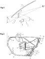
- FIG. 1 we have schematically represented the main elements of a head-up display 1 intended to equip a vehicle, for example a motor vehicle.
- Such a display 1 is suitable for creating a virtual image I in the field of vision of a driver of the vehicle, so that the driver can see this virtual image I and any information it contains without having to look away from it. the route taken.
- the head-up display 1 comprises a housing 2 and an image generation device 3 which produces a light beam representing an image to be displayed.
- said display 1 Downstream of the image generation device 3 according to the direction of movement of the light beam, said display 1 comprises a projection system 4 and a partially transparent plate 5.
- the partially transparent blade 5 can be merged with the windshield 6 of the vehicle.
- the projection system 4 is designed to project the light beam produced by the image generation device 3 in the direction of the partially transparent plate 5.
- the projection system 4 is therefore interposed on the path of the light beam between the generation device. image 3 and the partially transparent slide 5.
- the projection system 4 can comprise, in practice, one or more plane or concave mirrors and / or other optical elements.
- the box 2 comprises the image generation device 3 and an electronic system 7 capable of controlling the image generation device 3.
- the electronic system 7 comprises an electronic circuit 8 comprising at least one printed circuit 9.
- the invention aims to reduce the risk of condensation in the housing 2.
- the housing 2 comprises a ventilation system adapted to allow air circulation between the interior of the housing 2 and the outside environment, in the 'species, the vehicle interior.
- the housing 2 comprises vis-à-vis ventilation openings 10 which allow the outside air to penetrate inside the housing 2.
- the dimensions and shapes of the openings d ventilation 10 are adapted according to the size of the housing 2 and the thermal heat generated by a backlit screen 12 of the image generation device 3 when this screen 12 is illuminated by at least one light source 13.
- the ventilation openings 10 delimit passages, the surface of which is at the level of an outer face is between 5x15 mm 2 and 30x90 mm 2 , preferably 10x30mm 2 and 20x60 mm 2 .
- the ventilation openings 10 are of substantially parallelepipedal shape and each ventilation opening 10 defines a passage whose volume is between 5x15x40 mm 3 and 30x90x50 mm 3 , preferably 15x30x45 mm 3 and 20x60x45 mm 3 .
- the aeration system here further comprises filtration membranes 11 closing the openings 10, capable of preventing the passage of solid particles and allowing the passage of air and water vapor.
- the filtration membranes 11 cover the ventilation openings 10 at the outer faces of the housing 2. More specifically, the filtration membranes 11 are configured to prevent the passage of particles whose smallest dimension is equal to or greater than 0.07. ⁇ m, preferably equal to or greater than 0.1 ⁇ m.
- the filtration membranes 11 have an adhesive face allowing them to be positioned and held on an exterior face of the housing 2. The filtration membranes 11 thus prevent the introduction of particles or dust into the housing 2, while allowing a convection movement. ambient air between the interior and exterior of the housing 2.
- the filtration membranes 11 are configured to allow ambient air to flow through the ventilation openings 10, at a flow rate of air equal to or greater than 10 L / h at a pressure of 70 mbar.
- the filtration membranes 11 are also dark in color and configured to prevent ambient light from entering the housing 2, so as to preserve the intensity of the light beam emitted by the light source.
- a filtration membrane 11 according to the invention can for example be a product marketed by the company “GORE”, under the reference “Automotive Vents for Exterior Lighting”.
- the ventilation openings 10 pass through opposite walls of the housing 2.
- the ventilation openings 10 are arranged so as to pass through the housing 2 so that the ambient air passing through said openings 10 flows near a backlit screen 12.
- a first ventilation opening 10 is attached to the printed circuit 9
- a second ventilation opening 10 is located in the lower part of the housing 2, near the image generation device 3
- a third ventilation opening 10 is located in the upper part of the housing 2
- a fourth ventilation opening 10 is located in the upper part of the housing 2 near the projection system 4.
- the aeration system may further comprise means for generating air flow 14 capable of generating a forced air flow through the ventilation openings 10.
- an air blower 15 is arranged on the housing 2, facing a ventilation opening 10 blocked by a filtration membrane 11 described above.
- the operation of the air blower 15 can be controlled by means of a control unit not shown in the figure. figure 2 , depending on the operation of the display 1 and / or the temperature of the backlit display 12.
- the air blower 15 is configured to establish a forced air flow through the housing 2 which is sufficient. to allow its cooling and thus avoid the deterioration of its internal components.
Landscapes
- Physics & Mathematics (AREA)
- Engineering & Computer Science (AREA)
- General Physics & Mathematics (AREA)
- Optics & Photonics (AREA)
- Chemical & Material Sciences (AREA)
- Combustion & Propulsion (AREA)
- Transportation (AREA)
- Mechanical Engineering (AREA)
- Instrument Panels (AREA)
Abstract
Description
- La présente invention concerne de manière générale les afficheurs tête haute pour véhicule.
- Elle concerne plus particulièrement un afficheur tête haute comprenant un boîtier et un système d'aération adapté pour autoriser une circulation d'air entre l'intérieur du boîtier et le milieu extérieur.
- Le principe des afficheurs tête haute pour véhicule est de projeter des images, notamment utiles à la conduite, directement dans le champ de vision d'un conducteur.
- Pour cela, les afficheurs tête haute comprennent, en général, un boîtier, un dispositif de génération d'images, situé au moins en partie dans le boîtier, apte à produire un faisceau lumineux, et un système électronique, situé au moins en partie dans le boîtier, apte à piloter le dispositif de génération d'images.
- Le dispositif de génération d'images est adapté pour générer au moins un faisceau lumineux et un système de projection d'images transmet le faisceau lumineux généré vers une lame partiellement transparente, disposée de manière à recevoir ce faisceau lumineux et placée dans le champ de vision du conducteur. La taille du boîtier des afficheurs tête haute ne cesse d'augmenter, ce qui induit un risque de condensation de la vapeur d'eau dans le boîtier pouvant conduire à une altération des fonctions optiques et/ou électroniques.
- Afin de résoudre ce problème, l'afficheur tête haute, tel que mentionnée ci-dessus comprend un boîtier comprenant un système d'aération adapté pour autoriser une circulation d'air entre l'intérieur du boîtier et le milieu extérieur.
- Ainsi, le dispositif de génération d'images sera traversé par au moins un canal de flux d'air frais qui réduira les risques de condensation de la vapeur d'eau sur ses composants fonctionnels. La condensation (produite notamment à cause des variations de températures liées aux phases successives d'allumage et d'extinction de l'afficheur tête haute) est en effet notamment problématique en ce que cette condensation peut altérer la qualité des surfaces optiques et à long terme provoquer une dégradation des composants électroniques.
- D'autres caractéristiques avantageuses et non limitatives de l'afficheur tête haute conforme à l'invention sont les suivantes :
- le système d'aération comprend des ouvertures d'aération du boîtier,
- le système d'aération comprend au niveau d'au moins une ouverture d'aération des moyens de filtration apte à empêcher le passage des particules solides et autoriser le passage de l'air et de la vapeur d'eau
- les moyens de filtration sont configurés pour empêcher le passage de particules dont la plus petite dimension est égale ou supérieure à 0,07 µm,
- les moyens de filtration comprennent une membrane de filtration obturant les ouvertures,
- la membrane de filtration comporte une face adhésive permettant son maintien sur une face extérieure du boîtier,
- la membrane de filtration est configurée pour permettre à l'air ambiant de s'écouler à travers au moins une ouverture d'aération, selon un débit d'air égal ou supérieur à 10 L/h à une pression de 70 mbar,
- le boîtier comprend un système de projection, apte à diriger le faisceau lumineux produit par le dispositif de génération d'images en direction d'une lame partiellement transparente située dans le champ de vision d'un conducteur,
- au moins deux ouvertures d'aération sont en vis-à-vis des parois du boîtier,
- le système d'aération comprend des moyens de génération de flux d'air aptes à générer un flux d'air forcé au travers des ouvertures d'aération, et
- les moyens de génération de flux d'air comprennent un pulseur d'air.
- La description qui va suivre en regard du dessin annexé, donné à titre d'exemple non limitatif, fera bien comprendre en quoi consiste l'invention et comment elle peut être réalisée.
- Sur les dessins annexés :
- [
Fig.1 ] est une représentation schématique de principe d'un afficheur tête haute selon l'invention en position dans un véhicule ; - [
Fig 2 ] est une vue schématique en coupe d'un afficheur tête haute selon l'invention. - En préliminaire, on notera que les éléments identiques ou similaires des différents modes de réalisation de l'invention représentés sur les différentes figures seront, dans la mesure du possible, référencés par les mêmes signes de référence et ne seront pas décrits à chaque fois.
- Sur les figures, les proportions ne sont pas respectées afin de faire mieux ressortir la constitution des éléments présentés ci-dessous à titre d'exemples.
- Sur la
figure 1 , on a schématiquement représenté les éléments principaux d'un afficheur tête haute 1 destiné à équiper un véhicule, par exemple un véhicule automobile. - Un tel afficheur 1 est adapté à créer une image virtuelle I dans le champ de vision d'un conducteur du véhicule, de sorte que le conducteur puisse voir cette image virtuelle I et les informations éventuelles qu'elle contient sans avoir à détourner le regard de la route empruntée.
- A cet effet, l'afficheur tête haute 1 comprend un boîtier 2 et un dispositif de génération d'image 3 qui produit un faisceau lumineux représentant une image à afficher.
- En aval du dispositif de génération d'image 3 selon le sens de déplacement du faisceau lumineux, ledit afficheur 1 comprend un système de projection 4 et une lame partiellement transparente 5.
- En variante, la lame partiellement transparente 5 peut être confondue avec le parebrise 6 du véhicule.
- Le système de projection 4 est conçu pour projeter le faisceau lumineux produit par le dispositif de génération d'image 3 en direction de la lame partiellement transparente 5. Le système de projection 4 est donc interposé sur le trajet du faisceau lumineux entre le dispositif de génération d'image 3 et la lame partiellement transparente 5.
- Le système de projection 4 peut comprendre, en pratique, un ou plusieurs miroirs plans ou concaves et/ou d'autres éléments optiques.
- L'intérieur du boîtier 2 de l'afficheur tête haute est visible sur la
figure 2 . Selon cet exemple illustré, le boîtier 2 comprend le dispositif de génération d'images 3 et un système électronique 7 apte à piloter le dispositif de génération d'images 3. - Le système électronique 7 comprend un circuit électronique 8 comprenant au moins un circuit imprimé 9.
- L'invention vise à diminuer le risque de condensation dans le boîtier 2. A cet effet, le boîtier 2 comprend un système d'aération adapté pour autoriser une circulation d'air entre l'intérieur du boîtier 2 et le milieu extérieur, en l'espèce, l'habitacle du véhicule.
- Selon l'exemple illustré, le boîtier 2 comporte des ouvertures d'aération 10 en vis-à-vis qui permettent à l'air extérieur de pénétrer à l'intérieur du boîtier 2. Bien entendu, les dimensions et les formes des ouvertures d'aération 10 sont adaptées en fonction de la taille du boîtier 2 et de la chaleur thermique générée par un écran rétroéclairé 12 du dispositif de génération d'images 3 lorsque cet écran 12 est éclairé par au moins une source de lumière 13. À titre d'exemples non limitatif, les ouvertures d'aération 10 délimitent des passages dont la surface au niveau d'une face extérieure est comprise entre 5x15 mm2 et 30x90 mm2, de préférence 10x30mm2 et 20x60 mm2. Selon le présent exemple, les ouvertures d'aération 10 sont de forme sensiblement parallélépipédique et chaque ouverture d'aération 10 délimite un passage dont le volume est compris entre 5x15x40 mm3 et 30x90x50 mm3, de préférence 15x30x45 mm3 et 20x60x45 mm3.
- Le système d'aération comprend ici en outre des membranes de filtration 11 obturant les ouvertures 10, apte à empêcher le passage des particules solides et autoriser le passage de l'air et de la vapeur d'eau.
- Les membranes de filtration 11 recouvrent les ouvertures d'aération 10 au niveau des faces extérieures du boîtier 2. Plus précisément, les membranes de filtration 11 sont configurées pour empêcher le passage de particules dont la plus petite dimension est égale ou supérieure à 0,07 µm, de préférence égale ou supérieure à 0,1 µm. Les membranes de filtration 11 comportent une face adhésive permettant leur positionnement et leur maintien sur une face extérieure du boîtier 2. Les membranes de filtration 11 empêchent ainsi l'introduction de particules ou de poussières dans le boîtier 2, tout en permettant un mouvement de convection de l'air ambiant entre l'intérieur et l'extérieur du boîtier 2. De préférence, les membranes de filtration 11 sont configurées pour permettre un écoulement de l'air ambiant à travers les ouvertures d'aération 10, selon un débit d'air égal ou supérieur à 10 L/h à une pression de 70 mbar.
- Les membranes de filtration 11 sont également de couleur sombre et configurées pour empêcher à la lumière ambiante de pénétrer dans le boîtier 2, de manière à préserver l'intensité du faisceau lumineux émis par la source de lumière.
- À titre d'exemple non limitatif, une membrane de filtration 11 selon l'invention peut par exemple être un produit commercialisé par la société « GORE », sous la référence « Automotive Vents for Exterior Lighting ».
- Afin de favoriser l'écoulement de l'air dans le boîtier 2, les ouvertures d'aérations 10 traversent des parois opposées du boîtier 2. De préférence, les ouvertures d'aération 10 sont agencées de manière à être traversantes du boîtier 2 afin que l'air ambiant passant par lesdites ouvertures 10 s'écoule près d'un écran rétroéclairé 12. Selon le présent exemple, une première ouverture d'aération 10 est accolée au circuit imprimé 9, une deuxième ouverture d'aération 10 est située dans la partie basse du boîtier 2, près du dispositif de génération d'images 3, une troisième ouverture d'aération 10 est située dans la partie haute du boîtier 2 et une quatrième ouverture d'aération 10 est située dans la partie haute du boîtier 2 à proximité du système de projection 4. Ainsi, le risque de condensation de la vapeur d'eau est diminué sur les parties fonctionnelles situées dans le boîtier 2 de l'afficheur tête haute 1.
- Le système d'aération peut comprendre en outre des moyens de génération de flux d'air 14 aptes à générer un flux d'air forcé au travers des ouvertures d'aération 10.
- Selon l'exemple illustré, un pulseur d'air 15 est agencé sur le boîtier 2, en vis-à-vis d'une ouverture d'aération 10 obstruée par une membrane de filtration 11 décrite ci-dessus. Bien entendu, le fonctionnement du pulseur d'air 15 peut être contrôlé par l'intermédiaire d'une unité de commande non représentée sur la
figure 2 , en fonction du fonctionnement de l'afficheur 1 et/ou de la température de l'écran rétroéclairé 12. De préférence, le pulseur d'air 15 est configuré pour établir un écoulement d'air forcé à travers le boîtier 2 qui soit suffisant pour permettre son refroidissement et ainsi éviter la détérioration de ses composants internes. - Bien entendu, diverses autres modifications peuvent être apportées à l'invention dans le cadre des revendications annexées.
Claims (11)
- Afficheur tête haute (1) comprenant :- un boîtier (2),- un dispositif de génération d'images (3), situé au moins en partie dans le boîtier, apte à produire un faisceau lumineux, et- un système électronique, situé au moins en partie dans le boîtier (2), apte à piloter le dispositif de génération d'images (3),caractérisé en ce que le boîtier (2) comprend un système d'aération adapté pour autoriser une circulation d'air entre l'intérieur du boîtier (2) et le milieu extérieur.
- Afficheur tête haute selon la revendication 1, caractérisé en ce que le système d'aération comprend des ouvertures d'aération (10) du boîtier (2).
- Afficheur tête haute selon la revendication précédente, caractérisé en ce que le système d'aération comprend, au niveau d'au moins une ouverture d'aération (10), des moyens de filtration apte à empêcher le passage des particules solides et autoriser le passage de l'air et de la vapeur d'eau.
- Afficheur tête haute selon la revendication précédente, caractérisé en ce que les moyens de filtration sont configurés pour empêcher le passage de particules dont la plus petite dimension est égale ou supérieure à 0,07 µm.
- Afficheur tête haute selon l'une des revendications 3 ou 4, caractérisé en ce que les moyens de filtration comprennent une membrane de filtration (11) obturant les ouvertures (10).
- Afficheur tête haute selon l'une des revendications 3 à 5, caractérisé en ce que la membrane de filtration (11) comporte une face adhésive permettant son maintien sur une face extérieure du boîtier (2).
- Afficheur tête haute selon l'une des revendications 5 à 6, caractérisé en ce que la membrane de filtration (11) est configurée pour permettre à l'air ambiant de s'écouler à travers au moins une ouverture d'aération, selon un débit d'air égal ou supérieur à 10 L/h à une pression de 70 mbar.
- Afficheur tête haute selon l'une des revendications précédentes, caractérisé en ce qu'il comprend un système de projection (4), apte à diriger le faisceau lumineux produit par le dispositif de génération d'images (3) en direction d'une lame partiellement transparente (5) située dans le champ de vision d'un conducteur.
- Afficheur tête haute selon l'une des revendications 2 à 8, caractérisé en ce qu'au moins deux ouvertures d'aération (10) sont en vis-à-vis des parois du boîtier (2).
- Afficheur tête haute selon l'une des revendications précédentes, caractérisé en ce que le système d'aération comprend des moyens de génération de flux d'air aptes à générer un flux d'air forcé au travers des ouvertures d'aération.
- Afficheur tête haute selon la revendication précédente, caractérisé en ce que les moyens de génération de flux d'air comprennent un pulseur d'air (15).
Priority Applications (1)
| Application Number | Priority Date | Filing Date | Title |
|---|---|---|---|
| EP19183441.5A EP3757643B1 (fr) | 2019-06-28 | 2019-06-28 | Afficheur tête haute |
Applications Claiming Priority (1)
| Application Number | Priority Date | Filing Date | Title |
|---|---|---|---|
| EP19183441.5A EP3757643B1 (fr) | 2019-06-28 | 2019-06-28 | Afficheur tête haute |
Publications (2)
| Publication Number | Publication Date |
|---|---|
| EP3757643A1 true EP3757643A1 (fr) | 2020-12-30 |
| EP3757643B1 EP3757643B1 (fr) | 2023-03-29 |
Family
ID=67137744
Family Applications (1)
| Application Number | Title | Priority Date | Filing Date |
|---|---|---|---|
| EP19183441.5A Active EP3757643B1 (fr) | 2019-06-28 | 2019-06-28 | Afficheur tête haute |
Country Status (1)
| Country | Link |
|---|---|
| EP (1) | EP3757643B1 (fr) |
Citations (5)
| Publication number | Priority date | Publication date | Assignee | Title |
|---|---|---|---|---|
| JP2003118426A (ja) * | 2001-10-16 | 2003-04-23 | Honda Motor Co Ltd | 車両用ヘッドアップディスプレイ装置 |
| WO2016121269A1 (fr) * | 2015-01-27 | 2016-08-04 | 日本精機株式会社 | Dispositif d'affichage tête haute pour véhicule |
| EP3070511A2 (fr) * | 2015-02-27 | 2016-09-21 | Samsung Electronics Co., Ltd. | Dispositif électronique équipé de radiateur thermique et procédé pour commander ledit dispositif |
| DE102015016504A1 (de) * | 2015-12-18 | 2017-06-22 | Audi Ag | Anordnung eines HUD-Moduls in einem Kraftfahrzeug |
| EP3521886A1 (fr) * | 2018-02-05 | 2019-08-07 | Valeo Comfort and Driving Assistance | Afficheur tete haute pour vehicule automobile |
Family Cites Families (1)
| Publication number | Priority date | Publication date | Assignee | Title |
|---|---|---|---|---|
| CN209014815U (zh) * | 2017-09-07 | 2019-06-21 | 苹果公司 | 由用户佩戴的头戴式显示器 |
-
2019
- 2019-06-28 EP EP19183441.5A patent/EP3757643B1/fr active Active
Patent Citations (5)
| Publication number | Priority date | Publication date | Assignee | Title |
|---|---|---|---|---|
| JP2003118426A (ja) * | 2001-10-16 | 2003-04-23 | Honda Motor Co Ltd | 車両用ヘッドアップディスプレイ装置 |
| WO2016121269A1 (fr) * | 2015-01-27 | 2016-08-04 | 日本精機株式会社 | Dispositif d'affichage tête haute pour véhicule |
| EP3070511A2 (fr) * | 2015-02-27 | 2016-09-21 | Samsung Electronics Co., Ltd. | Dispositif électronique équipé de radiateur thermique et procédé pour commander ledit dispositif |
| DE102015016504A1 (de) * | 2015-12-18 | 2017-06-22 | Audi Ag | Anordnung eines HUD-Moduls in einem Kraftfahrzeug |
| EP3521886A1 (fr) * | 2018-02-05 | 2019-08-07 | Valeo Comfort and Driving Assistance | Afficheur tete haute pour vehicule automobile |
Also Published As
| Publication number | Publication date |
|---|---|
| EP3757643B1 (fr) | 2023-03-29 |
Similar Documents
| Publication | Publication Date | Title |
|---|---|---|
| EP1474305B1 (fr) | Dispositif d' affichage d' information pour vehicules | |
| EP3224669B1 (fr) | Dispositif de rétroéclairage notamment pour afficheur tête haute et afficheur tête haute pour véhicule automobile | |
| FR3062613A1 (fr) | Dispositif de projection pour vehicule | |
| EP3757643B1 (fr) | Afficheur tête haute | |
| EP3479167B1 (fr) | Ecran à cristaux liquides, dispositif de génération d'image comprenant un tel écran et afficheur tête haute comprenant un tel dispositif | |
| EP3479156B1 (fr) | Dispositif de génération d'images comprenant une zone de contact thermique, et afficheur tête haute associé | |
| EP3502546B1 (fr) | Module lumineux pour vehicule comprenant un dispositif de ventilation disposé entre deux dispositifs de dissipation de chaleur | |
| EP3491444B1 (fr) | Dispositif de génération d'images et afficheur tête haute associé | |
| FR3058236A1 (fr) | Ecran a cristaux liquides, dispositif de generation d'image comprenant un tel ecran et afficheur tete haute comprenant un tel dispositif | |
| FR3054328A1 (fr) | Dispositif de generation d'image et afficheur tete haute | |
| EP3273283B1 (fr) | Dispositif de génération d'image et afficheur tête haute comprenant un tel dispositif de génération d'image | |
| EP3631563B1 (fr) | Afficheur tête haute pour véhicule automobile | |
| EP3521886A1 (fr) | Afficheur tete haute pour vehicule automobile | |
| WO2021078905A1 (fr) | Afficheur tete-haute pour vehicule automobile et vehicule automobile comportant un tel afficheur | |
| EP3132304A1 (fr) | Dispositif de rétroéclairage notamment pour afficheur tête haute et afficheur tête haute pour véhicule automobile | |
| WO2014102464A1 (fr) | Afficheur, notamment afficheur tête haute, pour véhicule | |
| WO2023072520A1 (fr) | Dispositif de génération d'images | |
| EP3475123B1 (fr) | Ensemble de retroviseur de vehicule comprenant un dispositif de fixation d'une camera | |
| EP2936238B1 (fr) | Afficheur, notamment afficheur tête haute, pour véhicule | |
| EP3663834A1 (fr) | Afficheur tête haute pour véhicule automobile comprenant un radiateur pour refroidir un écran rétroéclairé | |
| FR3137438A1 (fr) | Module lumineux avec affichage par led optimisé pour application automobile | |
| EP4394482A1 (fr) | Dispositif de génération d'images, procédé de gestion de la température d'un tel dispositif et afficheur tête haute comportant ce dispositif | |
| WO2020088891A1 (fr) | Retroviseur intelligent pour vehicule automobile | |
| FR3057828A1 (fr) | Ensemble de planche de bord de vehicule integrant une camera | |
| FR3083332A1 (fr) | Afficheur tete haute |
Legal Events
| Date | Code | Title | Description |
|---|---|---|---|
| PUAI | Public reference made under article 153(3) epc to a published international application that has entered the european phase |
Free format text: ORIGINAL CODE: 0009012 |
|
| STAA | Information on the status of an ep patent application or granted ep patent |
Free format text: STATUS: THE APPLICATION HAS BEEN PUBLISHED |
|
| AK | Designated contracting states |
Kind code of ref document: A1 Designated state(s): AL AT BE BG CH CY CZ DE DK EE ES FI FR GB GR HR HU IE IS IT LI LT LU LV MC MK MT NL NO PL PT RO RS SE SI SK SM TR |
|
| AX | Request for extension of the european patent |
Extension state: BA ME |
|
| STAA | Information on the status of an ep patent application or granted ep patent |
Free format text: STATUS: REQUEST FOR EXAMINATION WAS MADE |
|
| 17P | Request for examination filed |
Effective date: 20210629 |
|
| RBV | Designated contracting states (corrected) |
Designated state(s): AL AT BE BG CH CY CZ DE DK EE ES FI FR GB GR HR HU IE IS IT LI LT LU LV MC MK MT NL NO PL PT RO RS SE SI SK SM TR |
|
| REG | Reference to a national code |
Ref country code: DE Ref legal event code: R079 Ref document number: 602019026811 Country of ref document: DE Free format text: PREVIOUS MAIN CLASS: G02B0007000000 Ipc: B60K0037040000 |
|
| GRAP | Despatch of communication of intention to grant a patent |
Free format text: ORIGINAL CODE: EPIDOSNIGR1 |
|
| STAA | Information on the status of an ep patent application or granted ep patent |
Free format text: STATUS: GRANT OF PATENT IS INTENDED |
|
| RIC1 | Information provided on ipc code assigned before grant |
Ipc: B60K 35/00 20060101ALI20220902BHEP Ipc: G02B 27/01 20060101ALI20220902BHEP Ipc: G02B 7/00 20060101ALI20220902BHEP Ipc: G02B 27/00 20060101ALI20220902BHEP Ipc: B60K 37/04 20060101AFI20220902BHEP |
|
| INTG | Intention to grant announced |
Effective date: 20221010 |
|
| GRAS | Grant fee paid |
Free format text: ORIGINAL CODE: EPIDOSNIGR3 |
|
| GRAA | (expected) grant |
Free format text: ORIGINAL CODE: 0009210 |
|
| STAA | Information on the status of an ep patent application or granted ep patent |
Free format text: STATUS: THE PATENT HAS BEEN GRANTED |
|
| AK | Designated contracting states |
Kind code of ref document: B1 Designated state(s): AL AT BE BG CH CY CZ DE DK EE ES FI FR GB GR HR HU IE IS IT LI LT LU LV MC MK MT NL NO PL PT RO RS SE SI SK SM TR |
|
| REG | Reference to a national code |
Ref country code: CH Ref legal event code: EP |
|
| REG | Reference to a national code |
Ref country code: DE Ref legal event code: R096 Ref document number: 602019026811 Country of ref document: DE |
|
| REG | Reference to a national code |
Ref country code: AT Ref legal event code: REF Ref document number: 1556447 Country of ref document: AT Kind code of ref document: T Effective date: 20230415 |
|
| REG | Reference to a national code |
Ref country code: IE Ref legal event code: FG4D Free format text: LANGUAGE OF EP DOCUMENT: FRENCH |
|
| RAP4 | Party data changed (patent owner data changed or rights of a patent transferred) |
Owner name: VALEO COMFORT AND DRIVING ASSISTANCE |
|
| REG | Reference to a national code |
Ref country code: LT Ref legal event code: MG9D |
|
| P01 | Opt-out of the competence of the unified patent court (upc) registered |
Effective date: 20230528 |
|
| PG25 | Lapsed in a contracting state [announced via postgrant information from national office to epo] |
Ref country code: RS Free format text: LAPSE BECAUSE OF FAILURE TO SUBMIT A TRANSLATION OF THE DESCRIPTION OR TO PAY THE FEE WITHIN THE PRESCRIBED TIME-LIMIT Effective date: 20230329 Ref country code: NO Free format text: LAPSE BECAUSE OF FAILURE TO SUBMIT A TRANSLATION OF THE DESCRIPTION OR TO PAY THE FEE WITHIN THE PRESCRIBED TIME-LIMIT Effective date: 20230629 Ref country code: LV Free format text: LAPSE BECAUSE OF FAILURE TO SUBMIT A TRANSLATION OF THE DESCRIPTION OR TO PAY THE FEE WITHIN THE PRESCRIBED TIME-LIMIT Effective date: 20230329 Ref country code: LT Free format text: LAPSE BECAUSE OF FAILURE TO SUBMIT A TRANSLATION OF THE DESCRIPTION OR TO PAY THE FEE WITHIN THE PRESCRIBED TIME-LIMIT Effective date: 20230329 Ref country code: HR Free format text: LAPSE BECAUSE OF FAILURE TO SUBMIT A TRANSLATION OF THE DESCRIPTION OR TO PAY THE FEE WITHIN THE PRESCRIBED TIME-LIMIT Effective date: 20230329 |
|
| REG | Reference to a national code |
Ref country code: NL Ref legal event code: MP Effective date: 20230329 |
|
| REG | Reference to a national code |
Ref country code: AT Ref legal event code: MK05 Ref document number: 1556447 Country of ref document: AT Kind code of ref document: T Effective date: 20230329 |
|
| PG25 | Lapsed in a contracting state [announced via postgrant information from national office to epo] |
Ref country code: SE Free format text: LAPSE BECAUSE OF FAILURE TO SUBMIT A TRANSLATION OF THE DESCRIPTION OR TO PAY THE FEE WITHIN THE PRESCRIBED TIME-LIMIT Effective date: 20230329 Ref country code: NL Free format text: LAPSE BECAUSE OF FAILURE TO SUBMIT A TRANSLATION OF THE DESCRIPTION OR TO PAY THE FEE WITHIN THE PRESCRIBED TIME-LIMIT Effective date: 20230329 Ref country code: GR Free format text: LAPSE BECAUSE OF FAILURE TO SUBMIT A TRANSLATION OF THE DESCRIPTION OR TO PAY THE FEE WITHIN THE PRESCRIBED TIME-LIMIT Effective date: 20230630 Ref country code: FI Free format text: LAPSE BECAUSE OF FAILURE TO SUBMIT A TRANSLATION OF THE DESCRIPTION OR TO PAY THE FEE WITHIN THE PRESCRIBED TIME-LIMIT Effective date: 20230329 |
|
| PG25 | Lapsed in a contracting state [announced via postgrant information from national office to epo] |
Ref country code: SM Free format text: LAPSE BECAUSE OF FAILURE TO SUBMIT A TRANSLATION OF THE DESCRIPTION OR TO PAY THE FEE WITHIN THE PRESCRIBED TIME-LIMIT Effective date: 20230329 Ref country code: RO Free format text: LAPSE BECAUSE OF FAILURE TO SUBMIT A TRANSLATION OF THE DESCRIPTION OR TO PAY THE FEE WITHIN THE PRESCRIBED TIME-LIMIT Effective date: 20230329 Ref country code: PT Free format text: LAPSE BECAUSE OF FAILURE TO SUBMIT A TRANSLATION OF THE DESCRIPTION OR TO PAY THE FEE WITHIN THE PRESCRIBED TIME-LIMIT Effective date: 20230731 Ref country code: ES Free format text: LAPSE BECAUSE OF FAILURE TO SUBMIT A TRANSLATION OF THE DESCRIPTION OR TO PAY THE FEE WITHIN THE PRESCRIBED TIME-LIMIT Effective date: 20230329 Ref country code: EE Free format text: LAPSE BECAUSE OF FAILURE TO SUBMIT A TRANSLATION OF THE DESCRIPTION OR TO PAY THE FEE WITHIN THE PRESCRIBED TIME-LIMIT Effective date: 20230329 Ref country code: AT Free format text: LAPSE BECAUSE OF FAILURE TO SUBMIT A TRANSLATION OF THE DESCRIPTION OR TO PAY THE FEE WITHIN THE PRESCRIBED TIME-LIMIT Effective date: 20230329 |
|
| REG | Reference to a national code |
Ref country code: DE Ref legal event code: R079 Ref document number: 602019026811 Country of ref document: DE Free format text: PREVIOUS MAIN CLASS: B60K0037040000 Ipc: B60K0035500000 |
|
| PG25 | Lapsed in a contracting state [announced via postgrant information from national office to epo] |
Ref country code: SK Free format text: LAPSE BECAUSE OF FAILURE TO SUBMIT A TRANSLATION OF THE DESCRIPTION OR TO PAY THE FEE WITHIN THE PRESCRIBED TIME-LIMIT Effective date: 20230329 Ref country code: PL Free format text: LAPSE BECAUSE OF FAILURE TO SUBMIT A TRANSLATION OF THE DESCRIPTION OR TO PAY THE FEE WITHIN THE PRESCRIBED TIME-LIMIT Effective date: 20230329 Ref country code: IS Free format text: LAPSE BECAUSE OF FAILURE TO SUBMIT A TRANSLATION OF THE DESCRIPTION OR TO PAY THE FEE WITHIN THE PRESCRIBED TIME-LIMIT Effective date: 20230729 |
|
| RAP4 | Party data changed (patent owner data changed or rights of a patent transferred) |
Owner name: VALEO COMFORT AND DRIVING ASSISTANCE |
|
| REG | Reference to a national code |
Ref country code: DE Ref legal event code: R097 Ref document number: 602019026811 Country of ref document: DE |
|
| PG25 | Lapsed in a contracting state [announced via postgrant information from national office to epo] |
Ref country code: MC Free format text: LAPSE BECAUSE OF FAILURE TO SUBMIT A TRANSLATION OF THE DESCRIPTION OR TO PAY THE FEE WITHIN THE PRESCRIBED TIME-LIMIT Effective date: 20230329 |
|
| PG25 | Lapsed in a contracting state [announced via postgrant information from national office to epo] |
Ref country code: MC Free format text: LAPSE BECAUSE OF FAILURE TO SUBMIT A TRANSLATION OF THE DESCRIPTION OR TO PAY THE FEE WITHIN THE PRESCRIBED TIME-LIMIT Effective date: 20230329 Ref country code: DK Free format text: LAPSE BECAUSE OF FAILURE TO SUBMIT A TRANSLATION OF THE DESCRIPTION OR TO PAY THE FEE WITHIN THE PRESCRIBED TIME-LIMIT Effective date: 20230329 Ref country code: CZ Free format text: LAPSE BECAUSE OF FAILURE TO SUBMIT A TRANSLATION OF THE DESCRIPTION OR TO PAY THE FEE WITHIN THE PRESCRIBED TIME-LIMIT Effective date: 20230329 |
|
| REG | Reference to a national code |
Ref country code: CH Ref legal event code: PL |
|
| PLBE | No opposition filed within time limit |
Free format text: ORIGINAL CODE: 0009261 |
|
| STAA | Information on the status of an ep patent application or granted ep patent |
Free format text: STATUS: NO OPPOSITION FILED WITHIN TIME LIMIT |
|
| REG | Reference to a national code |
Ref country code: BE Ref legal event code: MM Effective date: 20230630 |
|
| GBPC | Gb: european patent ceased through non-payment of renewal fee |
Effective date: 20230629 |
|
| PG25 | Lapsed in a contracting state [announced via postgrant information from national office to epo] |
Ref country code: LU Free format text: LAPSE BECAUSE OF NON-PAYMENT OF DUE FEES Effective date: 20230628 |
|
| 26N | No opposition filed |
Effective date: 20240103 |
|
| REG | Reference to a national code |
Ref country code: IE Ref legal event code: MM4A |
|
| PG25 | Lapsed in a contracting state [announced via postgrant information from national office to epo] |
Ref country code: LU Free format text: LAPSE BECAUSE OF NON-PAYMENT OF DUE FEES Effective date: 20230628 |
|
| PG25 | Lapsed in a contracting state [announced via postgrant information from national office to epo] |
Ref country code: IE Free format text: LAPSE BECAUSE OF NON-PAYMENT OF DUE FEES Effective date: 20230628 |
|
| PG25 | Lapsed in a contracting state [announced via postgrant information from national office to epo] |
Ref country code: IE Free format text: LAPSE BECAUSE OF NON-PAYMENT OF DUE FEES Effective date: 20230628 Ref country code: CH Free format text: LAPSE BECAUSE OF NON-PAYMENT OF DUE FEES Effective date: 20230630 Ref country code: GB Free format text: LAPSE BECAUSE OF NON-PAYMENT OF DUE FEES Effective date: 20230629 |
|
| PG25 | Lapsed in a contracting state [announced via postgrant information from national office to epo] |
Ref country code: SI Free format text: LAPSE BECAUSE OF FAILURE TO SUBMIT A TRANSLATION OF THE DESCRIPTION OR TO PAY THE FEE WITHIN THE PRESCRIBED TIME-LIMIT Effective date: 20230329 |
|
| PG25 | Lapsed in a contracting state [announced via postgrant information from national office to epo] |
Ref country code: SI Free format text: LAPSE BECAUSE OF FAILURE TO SUBMIT A TRANSLATION OF THE DESCRIPTION OR TO PAY THE FEE WITHIN THE PRESCRIBED TIME-LIMIT Effective date: 20230329 Ref country code: IT Free format text: LAPSE BECAUSE OF FAILURE TO SUBMIT A TRANSLATION OF THE DESCRIPTION OR TO PAY THE FEE WITHIN THE PRESCRIBED TIME-LIMIT Effective date: 20230329 Ref country code: BE Free format text: LAPSE BECAUSE OF NON-PAYMENT OF DUE FEES Effective date: 20230630 |
|
| PG25 | Lapsed in a contracting state [announced via postgrant information from national office to epo] |
Ref country code: BG Free format text: LAPSE BECAUSE OF FAILURE TO SUBMIT A TRANSLATION OF THE DESCRIPTION OR TO PAY THE FEE WITHIN THE PRESCRIBED TIME-LIMIT Effective date: 20230329 |
|
| PG25 | Lapsed in a contracting state [announced via postgrant information from national office to epo] |
Ref country code: BG Free format text: LAPSE BECAUSE OF FAILURE TO SUBMIT A TRANSLATION OF THE DESCRIPTION OR TO PAY THE FEE WITHIN THE PRESCRIBED TIME-LIMIT Effective date: 20230329 |
|
| PG25 | Lapsed in a contracting state [announced via postgrant information from national office to epo] |
Ref country code: CY Free format text: LAPSE BECAUSE OF FAILURE TO SUBMIT A TRANSLATION OF THE DESCRIPTION OR TO PAY THE FEE WITHIN THE PRESCRIBED TIME-LIMIT; INVALID AB INITIO Effective date: 20190628 |
|
| PG25 | Lapsed in a contracting state [announced via postgrant information from national office to epo] |
Ref country code: HU Free format text: LAPSE BECAUSE OF FAILURE TO SUBMIT A TRANSLATION OF THE DESCRIPTION OR TO PAY THE FEE WITHIN THE PRESCRIBED TIME-LIMIT; INVALID AB INITIO Effective date: 20190628 |
|
| PG25 | Lapsed in a contracting state [announced via postgrant information from national office to epo] |
Ref country code: TR Free format text: LAPSE BECAUSE OF FAILURE TO SUBMIT A TRANSLATION OF THE DESCRIPTION OR TO PAY THE FEE WITHIN THE PRESCRIBED TIME-LIMIT Effective date: 20230329 |
|
| PGFP | Annual fee paid to national office [announced via postgrant information from national office to epo] |
Ref country code: DE Payment date: 20260612 Year of fee payment: 8 |
|
| PGFP | Annual fee paid to national office [announced via postgrant information from national office to epo] |
Ref country code: FR Payment date: 20260630 Year of fee payment: 8 |