EP3757478B1 - Phase-change electric water heater and water temperature control method - Google Patents
Phase-change electric water heater and water temperature control method Download PDFInfo
- Publication number
- EP3757478B1 EP3757478B1 EP19776346.9A EP19776346A EP3757478B1 EP 3757478 B1 EP3757478 B1 EP 3757478B1 EP 19776346 A EP19776346 A EP 19776346A EP 3757478 B1 EP3757478 B1 EP 3757478B1
- Authority
- EP
- European Patent Office
- Prior art keywords
- outlet
- water
- heater
- circulation pipeline
- phase
- Prior art date
- Legal status (The legal status is an assumption and is not a legal conclusion. Google has not performed a legal analysis and makes no representation as to the accuracy of the status listed.)
- Active
Links
- XLYOFNOQVPJJNP-UHFFFAOYSA-N water Substances O XLYOFNOQVPJJNP-UHFFFAOYSA-N 0.000 title claims description 286
- 238000000034 method Methods 0.000 title claims description 39
- 239000012782 phase change material Substances 0.000 claims description 83
- 238000010438 heat treatment Methods 0.000 claims description 20
- 238000009825 accumulation Methods 0.000 claims description 9
- 238000011144 upstream manufacturing Methods 0.000 claims description 5
- 230000002277 temperature effect Effects 0.000 description 5
- 230000000694 effects Effects 0.000 description 4
- 241001657948 Midea Species 0.000 description 2
- 230000001464 adherent effect Effects 0.000 description 2
- 230000003247 decreasing effect Effects 0.000 description 2
- 230000017525 heat dissipation Effects 0.000 description 2
- 238000009413 insulation Methods 0.000 description 2
- 239000008399 tap water Substances 0.000 description 2
- 235000020679 tap water Nutrition 0.000 description 2
- 238000003287 bathing Methods 0.000 description 1
- 230000008020 evaporation Effects 0.000 description 1
- 238000001704 evaporation Methods 0.000 description 1
- 238000009434 installation Methods 0.000 description 1
Images

Classifications
-
- F—MECHANICAL ENGINEERING; LIGHTING; HEATING; WEAPONS; BLASTING
- F24—HEATING; RANGES; VENTILATING
- F24H—FLUID HEATERS, e.g. WATER OR AIR HEATERS, HAVING HEAT-GENERATING MEANS, e.g. HEAT PUMPS, IN GENERAL
- F24H7/00—Storage heaters, i.e. heaters in which the energy is stored as heat in masses for subsequent release
- F24H7/02—Storage heaters, i.e. heaters in which the energy is stored as heat in masses for subsequent release the released heat being conveyed to a transfer fluid
- F24H7/0208—Storage heaters, i.e. heaters in which the energy is stored as heat in masses for subsequent release the released heat being conveyed to a transfer fluid using electrical energy supply
-
- F—MECHANICAL ENGINEERING; LIGHTING; HEATING; WEAPONS; BLASTING
- F24—HEATING; RANGES; VENTILATING
- F24H—FLUID HEATERS, e.g. WATER OR AIR HEATERS, HAVING HEAT-GENERATING MEANS, e.g. HEAT PUMPS, IN GENERAL
- F24H9/00—Details
- F24H9/20—Arrangement or mounting of control or safety devices
- F24H9/2007—Arrangement or mounting of control or safety devices for water heaters
- F24H9/2014—Arrangement or mounting of control or safety devices for water heaters using electrical energy supply
- F24H9/2021—Storage heaters
-
- F—MECHANICAL ENGINEERING; LIGHTING; HEATING; WEAPONS; BLASTING
- F24—HEATING; RANGES; VENTILATING
- F24H—FLUID HEATERS, e.g. WATER OR AIR HEATERS, HAVING HEAT-GENERATING MEANS, e.g. HEAT PUMPS, IN GENERAL
- F24H15/00—Control of fluid heaters
- F24H15/10—Control of fluid heaters characterised by the purpose of the control
- F24H15/174—Supplying heated water with desired temperature or desired range of temperature
-
- F—MECHANICAL ENGINEERING; LIGHTING; HEATING; WEAPONS; BLASTING
- F24—HEATING; RANGES; VENTILATING
- F24H—FLUID HEATERS, e.g. WATER OR AIR HEATERS, HAVING HEAT-GENERATING MEANS, e.g. HEAT PUMPS, IN GENERAL
- F24H15/00—Control of fluid heaters
- F24H15/20—Control of fluid heaters characterised by control inputs
- F24H15/212—Temperature of the water
- F24H15/219—Temperature of the water after heating
-
- F—MECHANICAL ENGINEERING; LIGHTING; HEATING; WEAPONS; BLASTING
- F24—HEATING; RANGES; VENTILATING
- F24H—FLUID HEATERS, e.g. WATER OR AIR HEATERS, HAVING HEAT-GENERATING MEANS, e.g. HEAT PUMPS, IN GENERAL
- F24H15/00—Control of fluid heaters
- F24H15/20—Control of fluid heaters characterised by control inputs
- F24H15/238—Flow rate
-
- F—MECHANICAL ENGINEERING; LIGHTING; HEATING; WEAPONS; BLASTING
- F24—HEATING; RANGES; VENTILATING
- F24H—FLUID HEATERS, e.g. WATER OR AIR HEATERS, HAVING HEAT-GENERATING MEANS, e.g. HEAT PUMPS, IN GENERAL
- F24H15/00—Control of fluid heaters
- F24H15/30—Control of fluid heaters characterised by control outputs; characterised by the components to be controlled
- F24H15/305—Control of valves
- F24H15/315—Control of valves of mixing valves
-
- F—MECHANICAL ENGINEERING; LIGHTING; HEATING; WEAPONS; BLASTING
- F24—HEATING; RANGES; VENTILATING
- F24H—FLUID HEATERS, e.g. WATER OR AIR HEATERS, HAVING HEAT-GENERATING MEANS, e.g. HEAT PUMPS, IN GENERAL
- F24H15/00—Control of fluid heaters
- F24H15/30—Control of fluid heaters characterised by control outputs; characterised by the components to be controlled
- F24H15/335—Control of pumps, e.g. on-off control
-
- F—MECHANICAL ENGINEERING; LIGHTING; HEATING; WEAPONS; BLASTING
- F24—HEATING; RANGES; VENTILATING
- F24H—FLUID HEATERS, e.g. WATER OR AIR HEATERS, HAVING HEAT-GENERATING MEANS, e.g. HEAT PUMPS, IN GENERAL
- F24H15/00—Control of fluid heaters
- F24H15/30—Control of fluid heaters characterised by control outputs; characterised by the components to be controlled
- F24H15/355—Control of heat-generating means in heaters
- F24H15/37—Control of heat-generating means in heaters of electric heaters
-
- F—MECHANICAL ENGINEERING; LIGHTING; HEATING; WEAPONS; BLASTING
- F24—HEATING; RANGES; VENTILATING
- F24H—FLUID HEATERS, e.g. WATER OR AIR HEATERS, HAVING HEAT-GENERATING MEANS, e.g. HEAT PUMPS, IN GENERAL
- F24H9/00—Details
- F24H9/12—Arrangements for connecting heaters to circulation pipes
- F24H9/13—Arrangements for connecting heaters to circulation pipes for water heaters
- F24H9/133—Storage heaters
-
- F—MECHANICAL ENGINEERING; LIGHTING; HEATING; WEAPONS; BLASTING
- F28—HEAT EXCHANGE IN GENERAL
- F28D—HEAT-EXCHANGE APPARATUS, NOT PROVIDED FOR IN ANOTHER SUBCLASS, IN WHICH THE HEAT-EXCHANGE MEDIA DO NOT COME INTO DIRECT CONTACT
- F28D20/00—Heat storage plants or apparatus in general; Regenerative heat-exchange apparatus not covered by groups F28D17/00 or F28D19/00
- F28D20/02—Heat storage plants or apparatus in general; Regenerative heat-exchange apparatus not covered by groups F28D17/00 or F28D19/00 using latent heat
- F28D20/021—Heat storage plants or apparatus in general; Regenerative heat-exchange apparatus not covered by groups F28D17/00 or F28D19/00 using latent heat the latent heat storage material and the heat-exchanging means being enclosed in one container
-
- F—MECHANICAL ENGINEERING; LIGHTING; HEATING; WEAPONS; BLASTING
- F24—HEATING; RANGES; VENTILATING
- F24H—FLUID HEATERS, e.g. WATER OR AIR HEATERS, HAVING HEAT-GENERATING MEANS, e.g. HEAT PUMPS, IN GENERAL
- F24H15/00—Control of fluid heaters
- F24H15/10—Control of fluid heaters characterised by the purpose of the control
- F24H15/128—Preventing overheating
- F24H15/132—Preventing the operation of water heaters with low water levels, e.g. dry-firing
-
- Y—GENERAL TAGGING OF NEW TECHNOLOGICAL DEVELOPMENTS; GENERAL TAGGING OF CROSS-SECTIONAL TECHNOLOGIES SPANNING OVER SEVERAL SECTIONS OF THE IPC; TECHNICAL SUBJECTS COVERED BY FORMER USPC CROSS-REFERENCE ART COLLECTIONS [XRACs] AND DIGESTS
- Y02—TECHNOLOGIES OR APPLICATIONS FOR MITIGATION OR ADAPTATION AGAINST CLIMATE CHANGE
- Y02E—REDUCTION OF GREENHOUSE GAS [GHG] EMISSIONS, RELATED TO ENERGY GENERATION, TRANSMISSION OR DISTRIBUTION
- Y02E60/00—Enabling technologies; Technologies with a potential or indirect contribution to GHG emissions mitigation
- Y02E60/14—Thermal energy storage
Definitions
- the present disclosure relates to a water heater, and in particular relates to a phase-change electric water heater and a water temperature control method.
- Electric water heaters have been widely used due to its convenient and comfortable application and lower costs as compared to other types of water heaters such as a solar water heater.
- a conventional electric water heater is generally provided with a large water storage tank for heat accumulation, which causes the electric water heater to be large in size and requires a large space for installation.
- an electric water heater is usually provided with a thermostatic valve to adjust respective opening degrees for hot water and cold water in an outlet pipe.
- this method may achieve a certain constant temperature effect, over-high local temperature or dry-burning will occur in a water tank or a water pipe, which not only impairs the constant temperature effect, but also wastes electric energy, as well as leads to damages to some parts of the water heater.
- Documents CN106196604A and CN102654308 propose a phase-change electric water heater.
- the present invention proposes a phase-change electric water heater including a circulation pipeline; a phase-change material for heat accumulation; and a liner, provided with an accommodating space therein, wherein the phase-change material and a portion of the circulation pipeline that is in contact with the phase-change material are arranged in the accommodating space;
- the phase-change electric water heater further includes: an inlet pipe, connected to the circulation pipeline which is arranged inside the phase-change material through an inlet end of the circulation pipeline; and an outlet pipe, connected to the circulation pipeline which is arranged inside the phase-change material through an outlet end of the circulation pipeline.
- At least one heater has an inlet connected to an outlet of the pump.
- the circulation pipeline is further provided with a second temperature sensor for measuring a temperature of the phase-change material.
- the inlet pipe is provided with a second flow sensor for measuring an inlet water flow in the inlet pipe.
- outlet pipe is connected to the outlet end of the circulation pipeline via a thermostatic valve, and one end of the outlet pipe is connected to the thermostatic valve and the other end serving as a water outlet.
- the circulation pipeline is further provided with a first branch pipe, a three-way valve and a second branch pipe, the three-way valve has a first end connected to the outlet end of the circulation pipeline via the first branch pipe; a second end of the three-way valve is connected to the inlet pipe via the second branch pipe; and a third end of the three-way valve is connected to the outlet pipe; or the three-way valve connects the inlet end and the outlet end of the circulation pipeline, and one end of the outlet pipe is connected to the three-way valve, the other end serving as a water outlet.
- outlet pipe is further provided with a third temperature sensor for measuring an outlet water temperature in the outlet pipe.
- phase-change electric water heater further includes a one-way valve arranged at the circulation pipeline and configured to connect an outlet end and an inlet end of the circulation pipeline.
- the phase-change electric water heater further includes a temperature limiter arranged at a heater to limit a highest heating temperature.
- the phase-change electric water heater further includes a one-way relief valve arranged at an inlet pipe, wherein the one-way relief valve is spaced apart from and located upstream of a second flow sensor.
- the present disclosure provides in embodiments a phase-change electric water heater.
- the phase-change electric water heater includes: a circulation pipeline and a phase-change material for heat accumulation; wherein at least one side of the circulation pipeline is arranged to be adherent to the phase-change material, an inlet end or an outlet end of the circulation pipeline is provided sequentially with a pump, a heater, a first flow sensor for measuring an outlet water flow of a heater and a first temperature sensor for measuring an outlet water temperature of the heater; an inlet of the heater is connected to an outlet of a pump; the outlet end of the circulation pipeline is provided with a second temperature sensor for measuring a temperature of the phase-change material; the inlet end of the circulation pipeline is further provided with an inlet pipe, and the inlet pipe is provided with a second flow sensor for measuring an inlet water flow in the inlet pipe; the circulation pipeline is further provided with a three-way valve and an outlet pipe, the a first end of the three-way valve is connected to the outlet end of the circulation
- the present disclosure provides in embodiments a water temperature control method, controlling the phase-change electric water heater as described in embodiments of the aforementioned aspects.
- the water temperature control method includes: turning off an inlet pipe, turning on a pump and turning on a heater; driving, by the pump, water in a circulation pipeline to flow into the heater for heating; allowing heated water to flow into a portion of the circulation pipeline that is arranged in a phase-change material; allowing heat exchange to occur between the phase-change material and the heated water in the circulation pipeline; and turning off the pump and turning off the heater to stop working.
- the water temperature control method further includes: detecting a temperature of the phase-change material, and turning on the pump and turning on the heater for heating when the temperature of the phase-change material is lower than a first threshold temperature.
- the water temperature control method further includes: detecting a temperature of the phase-change material, and turning off the pump and turning off the heater to stop heating when the temperature of the phase-change material is lower than a second threshold temperature.
- the water temperature control method further includes: turning on the inlet pipe and an outlet pipe; detecting an outlet water temperature of the outlet pipe; adjusting an opening degree of a hot end of a three-way valve which is connected to an outlet end of the circulation pipeline and an opening degree of a cold end of the three-way valve which is connected to an inlet end of the circulation pipeline, when a difference between the outlet water temperature of the outlet pipe and a second threshold temperature is out of a preset range; and controlling water to be discharged from the outlet pipe when a third temperature sensor measures that the difference between the outlet water temperature of the outlet pipe and the second threshold temperature stays within the preset range.
- the water temperature control method further includes: turning on the pump to drive water flow towards the heater; and turning off the pump to stop driving when a first flow sensor measures that an outlet water flow of the heater is lower than a preset threshold.
- the water temperature control method further includes: turning on the inlet pipe; and turning off a cold end of a three-way valve which is connected to an inlet end of the circulation pipeline when water flows from the inlet pipe to the circulation pipeline for the first time.
- the water temperature control method further includes: detecting an outlet water temperature of the heater when the inlet pipe is turned off; and turning off the pump to stop driving and turning off the heater to stop working when the outlet water temperature of the heater achieves a third threshold temperature.
- the water temperature control method further includes: turning on the inlet pipe to allow water to flow from the inlet pipe into the heater through an inlet end of the circulation pipeline; turning on the heater when an outlet water temperature of the heater is lower than a fourth threshold temperature; heating, by the heater, the water entering the heater and detecting the outlet water temperature of the heater; and turning off the heater to stop working when the outlet water temperature of the heater achieves the fourth threshold temperature.
- the water temperature control method further includes: turning on the inlet pipe and an outlet pipe; detecting an outlet water temperature of the outlet pipe; when a difference between the outlet water temperature of the outlet pipe (150) and a second threshold temperature is out of a preset range, adjusting a thermostatic valve to allow the difference between the outlet water temperature of the outlet pipe and the second threshold temperature stays within the preset range; and controlling water to be discharged from the outlet pipe.
- the present disclosure provides in embodiments a phase-change electric water heater and a water temperature control method, where the phase-change material is capable of storing heat; when the temperature of water in the circulation pipeline is low, the water in the circulation pipeline will replace the heat stored in the phase-change material, thereby avoiding use of a storage water tank for heat accumulation, and thus reducing the size of the electric water heater; the first temperature sensor is used for measuring the outlet water temperature of the heater, the second temperature sensor is used for measuring the temperature of the phase-change material and the third temperature sensor is used for measuring the outlet water temperature of the outlet pipe, thereby not only avoiding over-high local water temperature but also guaranteeing a constant outlet water temperature, thus improving the constant temperature effect; and the first flow sensor is used to detect the outlet water flow of the heater, thus avoiding the pump from idling or stalling.
- a liner 100 an accommodating space 110; a phase-change material 120; a circulation pipeline 130; an inlet end 131 of the circulation pipeline 130; an outlet end 132 of the circulation pipeline 130; a second temperature sensor 140; an outlet pipe 150; a water outlet 151; a third temperature sensor152; a thermostatic valve 153; an inlet pipe 160; a water inlet 161; a second flow sensor 162; a one-way relief valve 163; a one-way valve 170; a pump 180; a heater 190; a temperature limiter 191; a first flow sensor 192; a first temperature sensor 193.
- orientation or position relationship such as “above”, “below”, “longitudinal”, “horizontal”, “top”, “bottom”, “inner” and “outer” should be construed to refer to the orientation or position relationship as then described or as shown in the drawings. These terms are merely for convenience and concision of description and do not alone indicate or imply that the device or element referred to must have a particular orientation or must be configured or operated in a particular orientation. Thus, it cannot be understood to limit the present disclosure.
- terms such as “first”, “second” and “third” are used herein for purposes of description and are not intended to indicate or imply relative importance or significance or impliedly indicate quantity of the technical feature referred to.
- upstream and “downstream” refer to the direction of water flow.
- the terms “mounted”, “connected”, “coupled”, “fixed” and the like are used broadly, and may be, for example, fixed connections, detachable connections, or integrated connections; may also be mechanical or electrical connections; may also be direct connections or indirect connections via intervening structures; may also be inner communications of two elements, which can be understood by those skilled in the art according to specific situations.
- the present disclosure provides in embodiment a phase-change electric water heater.
- the phase-change electric water heater includes: a circulation pipeline 130; a phase-change material 120 for heat accumulation; and a liner 100, provided with an accommodating space therein, wherein the phase-change material and a portion of the circulation pipeline that is in contact with the phase-change material are arranged in the accommodating space.
- the liner 100 is provided with the phase-change material 120, thus providing thermal insulation effect and preventing heat dissipation of the phase-change material 120.
- the phase-change electric water heater further includes: an inlet pipe 160, connected to the circulation pipeline 130 which is arranged inside the phase-change material 120 through an inlet end 131 of the circulation pipeline 130; and an outlet pipe 150, connected to the circulation pipeline 130 which is arranged inside the phase-change material 120 through an outlet end 132 of the circulation pipeline 130.
- the inlet end 131 or the outlet end 132 of the circulation pipeline 130 is provided with a pump 180 and a heater 190.
- At least one heater 190 has an inlet connected to an outlet of the pump 180.
- the inlet end 131 or the outlet end 132 of the circulation pipeline 130 is further provided with a first flow sensor 192 for measuring a water flow in the circulation pipeline 130.
- the inlet end 131 or the outlet end 132 of the circulation pipeline 130 is further provided with a first temperature sensor 193 for measuring a water temperature in the circulation pipeline 130.
- the first flow sensor 192 or the first temperature sensor 193 is arranged at a connecting pipe section between a water outlet of the heater 190 and the phase-change material 120.
- the circulation pipeline 130 is further provided with a second temperature sensor 140 for measuring a temperature of the phase-change material 120.
- the inlet pipe 160 is provided with a second flow sensor 162 for measuring an inlet water flow in the inlet pipe 160.
- the outlet pipe 150 is connected to the outlet end 132 of the circulation pipeline 130 via a thermostatic valve 153, and one end of the outlet pipe 150 is connected to the thermostatic valve 153 and the other end serving as a water outlet.
- the circulation pipeline 130 is further provided with a first branch pipe, a three-way valve and a second branch pipe, a first end of the three-way valve is connected to the outlet end 132 of the circulation pipeline 130 via the first branch pipe; a second end of the three-way valve is connected to the inlet pipe 160 via the second branch pipe; and a third end of three-way valve is connected to the outlet pipe 150; or the three-way valve connects the inlet end 131 and the outlet end 132 of the circulation pipeline 130, and one end of the outlet pipe 150 is connected to the three-way valve, the other end serving as a water outlet.
- the outlet pipe 150 is further provided with a third temperature sensor 152 for measuring an outlet water temperature in the outlet pipe 150.
- the phase-change electric water heater further includes a one-way valve 170 arranged at the circulation pipeline 130 and configured to connect the outlet end 132 and the inlet end 131 of the circulation pipeline 130.
- the phase-change electric water heater further includes a temperature limiter 191 arranged at the heater 190 to limit a highest heating temperature.
- the phase-change electric water heater further includes a one-way relief valve 163 arranged at the inlet pipe 160, wherein the one-way relief valve 163 is spaced apart from and located upstream of the second flow sensor 162.
- Figs. 1 to 3 exemplify the one-way relief valve 163 arranged at the inlet pipe 160, thereby avoiding water in the circulation pipeline 130 from backflow to the water inlet 161.
- the phase-change material 120 is used for heat accumulation or dissipation.
- heat exchange occurs between the phase-change material 120 and the heated water in the circulation pipeline 130, thus heat from the water in the circulation pipeline 130 is stored.
- the phase-change material 120 may also dissipate the saved heat to the water in the circulation pipeline 130, such that the water discharged from the outlet pipe 150 can meet supply demand.
- One end of the inlet pipe 160 is connected to the circulation pipeline 130 and the other end serving as a water inlet 161, which may be connected to a water source device outside the phase-change electric water heater.
- the water inlet 161 may be connected to a user's tap water pipe.
- the outlet pipe 150 connected to a three-way valve and the other end serving as a water outlet 151, which may be connected to a shower in a bathroom.
- An outlet water temperature of the heater 190 and the temperature of the phase-change material 120 are monitored by a first temperature sensor 193 and a second temperature sensor 140, respectively, thereby avoiding an over-high local water temperature or dry-burning, and thus guaranteeing a constant outlet water temperature.
- a contacting area between the circulation pipeline 130 and the phase-change material 120 is increased; the portion of the circulation pipeline 130 that is in contact with the phase-change material 120 is arranged in a spiral or serpentine shape; and the portion of the circulation pipeline 130 that is in contact with the phase-change material 120 may be arranged in parallel or in series.
- Fig. 1 exemplifies the portion of the circulation pipeline 130 that is in contact with the phase-change material 120 is arranged in a serpentine shape, and the water in the circulation pipeline 130 flows in a counterclockwise circulating direction.
- the three-way vale has a first end (the left end of the three-way valve as shown in Figs.
- the outlet water temperature can be controlled by adjusting respective opening degrees of the cold end and the hot end of the three-way valve, thereby improving the constant effect of the outlet water temperature.
- the three-way valve may be a thermostatic valve 153.
- the present disclosure provides in embodiment a phase-change electric water heater.
- the phase-change electric water heater includes: a circulation pipeline and a phase-change material for heat accumulation; wherein at least one side of the circulation pipeline 130 is arranged to be adherent to the phase-change material 120, an inlet end 131 of the circulation pipeline 130 is provided sequentially with a pump 180, a heater 190, a first flow sensor 192 for measuring an outlet water flow of the heater 190 and a first temperature sensor 193 for measuring an outlet water temperature of the heater 190 (as shown in Figs.
- an outlet end 132 of the circulation pipeline 130 is provided sequentially with a pump 180, a heater 190, a first flow sensor 192 for measuring an outlet water flow of the heater 190 and a first temperature sensor 193 for measuring an outlet water temperature of the heater 190 (as shown in Fig.
- an inlet of the heater 190 is connected to an outlet of the pump 180; the outlet end 132 of the circulation pipeline 130 is provided with a second temperature sensor 140 for measuring a temperature of the phase-change material 120; the inlet end 131 of the circulation pipeline 130 is further provided with an inlet pipe 160, and the inlet pipe 160 is provided with a second flow sensor 162 for measuring an inlet water flow in the inlet pipe 160; the outlet end 132 of the circulation pipeline 130 is further provided with a first branch pipe, a three-way valve, an outlet pipe 150 and a second branch pipe; a first end of the three-way valve is connected to the outlet end 132 of the circulation pipeline 130 via the first branch pipe; a second end of the three-way valve is connected to the inlet pipe 160 via the second branch pipe; and a third end of three-way valve is connected to the outlet pipe 150 (as shown in Fig.
- the circulation pipeline 130 is further provided with a three-way valve and an outlet pipe 150, the three-way valve connects the inlet end 131 and the outlet end 132 of the circulation pipeline 130, one end of the outlet pipe 150 is connected to the three-way valve, and the other end serving as a water outlet (as shown in Figs. 2 and 3 ); the outlet pipe 150 is further provided with a third temperature sensor 152 for measuring an outlet water temperature in the outlet pipe 150.
- the phase-change material 120 is used for heat accumulation or dissipation.
- heat exchange occurs between the phase-change material 120 and the heated water in the circulation pipeline 130, thus heat from the water in the circulation pipeline 130 is stored.
- the phase-change material 120 may also dissipate the saved heat to the water in the circulation pipeline 130, such that the water discharged from the outlet pipe 150 can meet supply demand.
- the water inlet 161 may be connected to a user's tap water pipe.
- One end of the outlet pipe 150 is connected to a three-way valve and the other end serving as a water outlet 151, which may be connected to a shower in a bathroom.
- An outlet water temperature of the heater 190 and the temperature of the phase-change material 120 are monitored by a first temperature sensor 193 and a second temperature sensor 140 respectively, thereby avoiding an over-high local water temperature or dry-burning, and thus guaranteeing a constant outlet water temperature.
- a contacting area between the circulation pipeline 130 and the phase-change material 120 is increased; the portion of the circulation pipeline 130 that is in contact with the phase-change material 120 is arranged in a spiral or serpentine shape; and the portion of the circulation pipeline 130 that is in contact with the phase-change material 120 may be arranged in parallel or in series.
- Fig. 1 exemplifies the portion of the circulation pipeline 130 that is in contact with the phase-change material 120 is arranged in a serpentine shape, and water in the circulation pipeline 130 flows in a counterclockwise circulating direction.
- the three-way vale has a first end (the left end of the three-way valve as shown in Figs.
- the outlet water temperature can be controlled by adjusting respective opening degrees of the cold end and the hot end of the three-way valve, thereby improving the constant effect of the outlet water temperature.
- the three-way valve may be a thermostatic valve 153.
- the phase-change electric water heater further includes a one-way valve 170 arranged at the circulation pipeline 130 and configured to connect the outlet end 132 and the inlet end 131 of the circulation pipeline 130.
- the one-way valve 170 only allows water to flow from the outlet end 132 of the circulation pipeline 130 to the inlet end 131 of the circulation pipeline 130, but forbids water to flow in the reverse direction, thereby ensuring that cold water flows towards the heater 190 after entering the circulation pipeline 130.
- the phase-change electric water heater further includes a temperature limiter 191 arranged at the heater 190 to limit a highest heating temperature.
- the heater 190 is provided with the temperature limiter 191, such that it is possible to prevent water evaporation due to over-high temperature during heating, thereby avoiding the water temperature from being over-high and thus improving the constant temperature effect.
- the phase-change electric water heater further includes a one-way relief valve 163 arranged at the inlet pipe 160, wherein the one-way relief valve 163 is spaced apart from and located upstream of the second flow sensor 162.
- Figs. 1 to 3 exemplify the one-way relief valve 163 arranged at the inlet pipe 160, thereby avoiding water in the circulation pipeline 130 from backflow to the water inlet 161.
- the phase-change electric water heater further includes a liner 100 provided with an accommodating space 110 therein, wherein the phase-change material 120 and a portion of the circulation pipeline 130 that is in contact with the phase-change material 120 are arranged in the accommodating space.
- the liner 100 is provided with the phase-change material 120, thus providing the thermal insulation effect and preventing heat dissipation of the phase-change material 120.
- the present disclosure provides in embodiments a water temperature control method, controlling the phase-change electric water heater as described in the aforementioned embodiments.
- the water temperature control method includes: turning off an inlet pipe 160, turning on a pump 180 and turning on a heater 190; driving, by the pump 180, water in a circulation pipeline 130 to flow into the heater 190 for heating; allowing heated water to flow into a portion of the circulation pipeline 130 that is arranged in a phase-change material 120; allowing heat exchange to occur between the phase-change material 120 and the heated water in the circulation pipeline 130; and turning off the pump 180 and turning off the heater 190 to stop working.
- the water temperature control method further includes: detecting a temperature of the phase-change material 120, and turning on the pump 180 and turning on the heater 190 for heating when the temperature of the phase-change material 120 is lower than a first threshold temperature.
- the water temperature control method further includes: detecting a temperature of the phase-change material 120, and turning off the pump 180 and turning off the heater 190 to stop heating when the temperature of the phase-change material 120 is lower than a second threshold temperature.
- the water temperature control method further includes: turning on an inlet pipe 160 and turning on an outlet pipe 150; detecting an outlet water temperature of the outlet pipe 150; adjusting an opening degree of a hot end of a three-way valve which is connected to an outlet end 132 of the circulation pipeline 130 and an opening degree of a cold end of the three-way valve which is connected to an inlet end 131 of the circulation pipeline 130, when a difference between the outlet water temperature of the outlet pipe 150 and a second threshold temperature is out of a preset range; and controlling water to be discharged from the outlet pipe 150 when a third temperature sensor 152 measures that the difference between the outlet water temperature of the outlet pipe 150 and the second threshold temperature stays within the preset range.
- the water temperature control method further includes: turning on the pump 180 to drive water flow to the heater 190; and turning off the pump 180 to stop driving when a first flow sensor 192 measures that an outlet water flow of the heater 190 is lower than a preset threshold.
- the water temperature control method further includes: turning on an inlet pipe 160; and turning off a cold end of a three-way valve which is connected to an inlet end 131 of the circulation pipeline 130 when water flows from the inlet pipe 160 to the circulation pipeline 130 for the first time.
- the water temperature control method further includes: detecting an outlet water temperature of the heater 190 when the inlet pipe 160 is turned off; and turning off the pump 180 to stop driving and turning off the heater 190 to stop working when the outlet water temperature of the heater 190 achieves a third threshold temperature.
- the water temperature control method further includes: turning on an inlet pipe 160 to allow water to flow from the inlet pipe 160 into the heater 190 through an inlet end 131 of the circulation pipeline 130; turning on the heater 190 when an outlet water temperature of the heater 190 is lower than a fourth threshold temperature; heating, by the heater 190, the water entering the heater 190 and detecting the outlet water temperature of the heater 190; and turning off the heater 190 to stop working when the outlet water temperature of the heater 190 achieves the fourth threshold temperature.
- the water temperature control method further includes: turning on an inlet pipe 160 and an outlet pipe 150; detecting an outlet water temperature of the outlet pipe 150; when a difference between the outlet water temperature of the outlet pipe (150) and a second threshold temperature is out of a preset range, adjusting a thermostatic valve 153 to allow the difference between the outlet water temperature of the outlet pipe 150 and the second threshold temperature stays within the preset range; and controlling water to be discharged from the outlet pipe 150.
- the present disclosure provides in embodiments a water temperature control method, controlling the phase-change electric water heater as described in the aforementioned embodiments.
- the water temperature control method includes: turning on a pump 180 and turning on a heater 190 when an inlet pipe 160 is turned off and a second temperature sensor 140 measures that a temperature of a phase-change material 120 is lower than a first threshold temperature; driving, by the pump 180, water in a circulation pipeline 130 to flow in a direction from the outlet end 132 to the inlet end 131 of the circulation pipeline 130; allowing water to flow into the heater 190 for heating; allowing heated water to flow into the circulation pipeline 130 again from the inlet end 131 of the circulation pipeline 130, allowing heat exchange to occur between the phase-change material 120 and the heated water in the circulation pipeline 130; and turning off the pump 180 to stop driving and turning off the heater 190 to stop working when the second temperature sensor 140 measures that the temperature of the phase-change material 120 achieves the first threshold temperature.
- the pump 180 is turned on when the inlet pipe 160 is turned off and the second temperature sensor 140 measures that the temperature of the phase-change material 120 is lower than the first threshold temperature.
- the pump 180 may be turned on after the temperature of the phase-change material 120 is lower than the first threshold temperature for a certain temperature range. For example, the pump 180 is turned on when the temperature of the phase-change material 120 is -5°C lower than the first threshold temperature.
- the temperature of the phase-change material 120 may be a temperature of the phase-change material 120 itself, or may be a temperature of water in the portion of the circulation pipeline 130 that is in contact with the phase-change material 120.
- the first temperature sensor 193 measures an outlet water temperature of the heater 190 in real time.
- the heater 190 is turned on within a first preset duration, e.g., 6s, 10s, 12s or 15s, when the first temperature sensor 193 measures that the outlet water temperature of the heater 190 is less than a third threshold temperature, for example when the first temperature sensor 193 measures that the outlet water temperature of the heater 190 is less than 88°C, 90°C, 91°C, 93°C, 95°C or 98°C.
- the pump 180 drives water in the circulation pipeline 130 to flow in a direction from the outlet end 132 to the inlet end 131 of the circulation pipeline 130; water is then allowed to flow into the heater 190 for heating; heated water is then allowed to flow into the circulation pipeline 130 again from the inlet end 131 of the circulation pipeline 130; heat exchange is allowed to occur between the phase-change material 120 and the heated water in the circulation pipeline 130; and the pump 180 is turned off to stop driving and the heater 190 is turned off to stop working when the second temperature sensor 140 measures that the temperature of the phase-change material 120 achieves the first threshold temperature.
- the heater 190 is turned off, e.g., by cutting off power supply for the heater 190, when the temperature of the phase-change material 120 is equal to or greater than the first threshold temperature.
- the pump may continue working for a second preset duration, e.g., 20s, 30s, 40s or 45s, till turned off.
- the above control mode is the working mode of the phase-change electric water heater when the inlet pipe 160 is turned off, i.e., the second flow sensor 162 detects that the inlet water flow of the inlet pipe 160 is zero.
- the working mode of the phase-change electric water heater includes: turning on the heater 190 when the first flow sensor 192 measures an outlet water flow of the heater 190 is greater than a preset flow and the first temperature sensor 193 measures that an outlet water temperature of the heater 190 is greater than a fourth threshold temperature, for example, when the first flow sensor 192 measures the outlet water flow of the heater 190 is greater than 2 L/min, 3 L/ min or 5 L/ min and the first temperature sensor 193 measures that the outlet water temperature of the heater 190 is greater than 88°C, 90°C, 91°C, 93°C, 95°C or 98°C; otherwise allowing the heater 190 not to heat.
- the fourth threshold temperature may be equal to the first threshold temperature.
- the water temperature control method further includes: adjusting an opening degree of a hot end of a three-way valve which is connected to an outlet end 132 of the circulation pipeline 130 and an opening degree of a cold end of the three-way valve which is connected to an inlet end 131 of the circulation pipeline 130, when a third temperature sensor 152 measures that a difference between an outlet water temperature of an outlet pipe 150 and a second threshold temperature is out of a preset range; and controlling water to be discharged from the outlet pipe 150 when the third temperature sensor 152 measures that the difference between the outlet water temperature of the outlet pipe 150 and the second threshold temperature stays within the preset range.
- the third temperature sensor 152 may be arranged at one end of the outlet pipe 150 which is connected to the three-way valve, that is, a temperature of the outlet pipe 150 detected by the third temperature sensor 152 refers to a water temperature at an outlet end of the three-way valve.
- the three-way valve may be connected to an electric motor such that the respective opening degrees of the cold end and the hot end of the three-way valve may be controlled by the electric motor.
- a preset range for a difference between an outlet water temperature of the three-way valve and the fourth threshold temperature may be set as 0 to 2°C, 0 to 3°C, 0 to 4°C or 0 to 5°C.
- the opening degree of the hot end of the three-way vale is decreased and the opening degree of the cold end of the three-way vale is increased by the electric motor, when the outlet water temperature of the outlet pipe 150, e.g., the outlet water temperature of the three-way valve, is 2°C or more greater than the fourth preset temperature.
- the opening degree of the hot end of the three-way vale is increased and the opening degree of the cold end of the three-way vale is decreased by the electric motor, when the outlet water temperature of the three-way valve is 2°C or more greater than the fourth preset temperature.
- the outlet pipe 150 is controlled to discharge water when the difference between the outlet water temperature of the three-way valve and the fourth preset temperature is within 2°C by continuous measuring and adjusting.
- the water temperature control method further includes: turning on the pump 180; driving, by the pump 180, water to flow towards the heater 190; and turning off the pump 180 to stop driving when the first flow sensor 192 measures that the outlet water flow of the heater 190 is lower than a preset threshold.
- the pump 180 is turned on to drive water flow towards the heater 190
- the pump 180 is turned off to stop driving. If the first flow sensor 192 measures that the outlet water flow of the heater 190 is not 0 L/min, or not below 0.1 L/min or 0.5 L/min, the pump 180 continues working.
- the water temperature control method further includes: turning on the inlet pipe 160; and turning off the cold end of the three-way valve which is connected to the inlet end 131 of the circulation pipeline 130 when water flows from the inlet pipe 160 to the circulation pipeline 130 for the first time. It would be appreciated that when the phase-change electric water heater is used for the first time, it needs to be watered at first to ensure that there is water in the circulation pipeline 130.
- the water temperature control method further includes: turning off the pump 180 to stop driving and turning off the heater 190 to stop working when the inlet pipe 160 is turned off and the first temperature sensor 193 measures that an outlet water temperature of the heater 190 achieves the third temperature threshold.
- the water temperature control method further includes: turning on the inlet pipe 160, allowing water to flow from the inlet pipe 160 into the heater 190 via the inlet end 131 of the circulation pipeline 130; turning on the heater 190 when the first temperature sensor 193 measures that the outlet water temperature of the heater 190 is less than the fourth temperature threshold; heating, by the heater 190, water entering the heater 190; and turning off the heater 190 to stop working when the first temperature sensor 193 measures that the outlet water temperature of the heater 190 achieves the fourth temperature threshold.
- phase-change electric water heater According to embodiments of the present disclosure are understandable and easy to implement for those skilled in the art, and therefore will not be described in detail.
Description
- This application claims priorities to Chinese Patent Application Serial No.
CN201810260304.X CN201810259828.7 CN201820424639.6 CN201820424736.5 as a utility model titled with "phase-change electric water heater", all of which were filed with the National Intellectual Property Administration of PRC on March 27, 2018 - The present disclosure relates to a water heater, and in particular relates to a phase-change electric water heater and a water temperature control method.
- Electric water heaters have been widely used due to its convenient and comfortable application and lower costs as compared to other types of water heaters such as a solar water heater. A conventional electric water heater is generally provided with a large water storage tank for heat accumulation, which causes the electric water heater to be large in size and requires a large space for installation. In order to improve bathing comfort and achieve a constant temperature effect, an electric water heater is usually provided with a thermostatic valve to adjust respective opening degrees for hot water and cold water in an outlet pipe. Although this method may achieve a certain constant temperature effect, over-high local temperature or dry-burning will occur in a water tank or a water pipe, which not only impairs the constant temperature effect, but also wastes electric energy, as well as leads to damages to some parts of the water heater. Documents
CN106196604A andCN102654308 propose a phase-change electric water heater. - In order to address the above technical problem, the present invention proposes a phase-change electric water heater including a circulation pipeline; a phase-change material for heat accumulation; and a liner, provided with an accommodating space therein, wherein the phase-change material and a portion of the circulation pipeline that is in contact with the phase-change material are arranged in the accommodating space;
- according to the present embodiment, an inlet end or an outlet end of the circulation pipeline is provided with a pump and a heater,
- wherein an inlet end or an outlet end of the circulation pipeline is further provided with a first flow sensor for measuring a water flow in the circulation pipeline,
- wherein an inlet end or an outlet end of the circulation pipeline is further provided with a first temperature sensor for measuring a water temperature in the circulation pipeline,
- wherein the first flow sensor or the first temperature sensor is arranged at a connecting pipe section between a water outlet of a heater and the phase-change material.
- Further, the phase-change electric water heater further includes: an inlet pipe, connected to the circulation pipeline which is arranged inside the phase-change material through an inlet end of the circulation pipeline; and an outlet pipe, connected to the circulation pipeline which is arranged inside the phase-change material through an outlet end of the circulation pipeline.
- Further, at least one heater has an inlet connected to an outlet of the pump.
- Further, the circulation pipeline is further provided with a second temperature sensor for measuring a temperature of the phase-change material.
- Further, the inlet pipe is provided with a second flow sensor for measuring an inlet water flow in the inlet pipe.
- Further, the outlet pipe is connected to the outlet end of the circulation pipeline via a thermostatic valve, and one end of the outlet pipe is connected to the thermostatic valve and the other end serving as a water outlet.
- Further, the circulation pipeline is further provided with a first branch pipe, a three-way valve and a second branch pipe, the three-way valve has a first end connected to the outlet end of the circulation pipeline via the first branch pipe; a second end of the three-way valve is connected to the inlet pipe via the second branch pipe; and a third end of the three-way valve is connected to the outlet pipe; or the three-way valve connects the inlet end and the outlet end of the circulation pipeline, and one end of the outlet pipe is connected to the three-way valve, the other end serving as a water outlet.
- Further, the outlet pipe is further provided with a third temperature sensor for measuring an outlet water temperature in the outlet pipe.
- Further, the phase-change electric water heater further includes a one-way valve arranged at the circulation pipeline and configured to connect an outlet end and an inlet end of the circulation pipeline.
- Further, the phase-change electric water heater further includes a temperature limiter arranged at a heater to limit a highest heating temperature.
- Further, the phase-change electric water heater further includes a one-way relief valve arranged at an inlet pipe, wherein the one-way relief valve is spaced apart from and located upstream of a second flow sensor.
- As an example to carry out the present disclosure, the present disclosure provides in embodiments a phase-change electric water heater. The phase-change electric water heater includes: a circulation pipeline and a phase-change material for heat accumulation; wherein at least one side of the circulation pipeline is arranged to be adherent to the phase-change material, an inlet end or an outlet end of the circulation pipeline is provided sequentially with a pump, a heater, a first flow sensor for measuring an outlet water flow of a heater and a first temperature sensor for measuring an outlet water temperature of the heater; an inlet of the heater is connected to an outlet of a pump; the outlet end of the circulation pipeline is provided with a second temperature sensor for measuring a temperature of the phase-change material; the inlet end of the circulation pipeline is further provided with an inlet pipe, and the inlet pipe is provided with a second flow sensor for measuring an inlet water flow in the inlet pipe; the circulation pipeline is further provided with a three-way valve and an outlet pipe, the a first end of the three-way valve is connected to the outlet end of the circulation pipeline via a first branch pipe; a second end of the three-way valve is connected to the inlet pipe via a second branch pipe, and a third end of three-way valve is connected to the outlet pipe; or the three-way valve connects the inlet end and the outlet end of the circulation pipeline; one end of the outlet pipe is connected to the three-way valve, and the other end serving as a water outlet; the outlet pipe is further provided with a third temperature sensor for measuring an outlet water temperature in the outlet pipe.
- In another aspect, the present disclosure provides in embodiments a water temperature control method, controlling the phase-change electric water heater as described in embodiments of the aforementioned aspects. The water temperature control method includes: turning off an inlet pipe, turning on a pump and turning on a heater; driving, by the pump, water in a circulation pipeline to flow into the heater for heating; allowing heated water to flow into a portion of the circulation pipeline that is arranged in a phase-change material; allowing heat exchange to occur between the phase-change material and the heated water in the circulation pipeline; and turning off the pump and turning off the heater to stop working.
- Further, the water temperature control method further includes: detecting a temperature of the phase-change material, and turning on the pump and turning on the heater for heating when the temperature of the phase-change material is lower than a first threshold temperature.
- Further, the water temperature control method further includes: detecting a temperature of the phase-change material, and turning off the pump and turning off the heater to stop heating when the temperature of the phase-change material is lower than a second threshold temperature.
- Further, the water temperature control method further includes: turning on the inlet pipe and an outlet pipe; detecting an outlet water temperature of the outlet pipe; adjusting an opening degree of a hot end of a three-way valve which is connected to an outlet end of the circulation pipeline and an opening degree of a cold end of the three-way valve which is connected to an inlet end of the circulation pipeline, when a difference between the outlet water temperature of the outlet pipe and a second threshold temperature is out of a preset range; and controlling water to be discharged from the outlet pipe when a third temperature sensor measures that the difference between the outlet water temperature of the outlet pipe and the second threshold temperature stays within the preset range.
- Further, the water temperature control method further includes: turning on the pump to drive water flow towards the heater; and turning off the pump to stop driving when a first flow sensor measures that an outlet water flow of the heater is lower than a preset threshold.
- Further, the water temperature control method further includes: turning on the inlet pipe; and turning off a cold end of a three-way valve which is connected to an inlet end of the circulation pipeline when water flows from the inlet pipe to the circulation pipeline for the first time.
- Further, the water temperature control method further includes: detecting an outlet water temperature of the heater when the inlet pipe is turned off; and turning off the pump to stop driving and turning off the heater to stop working when the outlet water temperature of the heater achieves a third threshold temperature.
- Further, the water temperature control method further includes: turning on the inlet pipe to allow water to flow from the inlet pipe into the heater through an inlet end of the circulation pipeline; turning on the heater when an outlet water temperature of the heater is lower than a fourth threshold temperature; heating, by the heater, the water entering the heater and detecting the outlet water temperature of the heater; and turning off the heater to stop working when the outlet water temperature of the heater achieves the fourth threshold temperature.
- Further, the water temperature control method further includes: turning on the inlet pipe and an outlet pipe; detecting an outlet water temperature of the outlet pipe; when a difference between the outlet water temperature of the outlet pipe (150) and a second threshold temperature is out of a preset range, adjusting a thermostatic valve to allow the difference between the outlet water temperature of the outlet pipe and the second threshold temperature stays within the preset range; and controlling water to be discharged from the outlet pipe.
- The present disclosure provides in embodiments a phase-change electric water heater and a water temperature control method, where the phase-change material is capable of storing heat; when the temperature of water in the circulation pipeline is low, the water in the circulation pipeline will replace the heat stored in the phase-change material, thereby avoiding use of a storage water tank for heat accumulation, and thus reducing the size of the electric water heater; the first temperature sensor is used for measuring the outlet water temperature of the heater, the second temperature sensor is used for measuring the temperature of the phase-change material and the third temperature sensor is used for measuring the outlet water temperature of the outlet pipe, thereby not only avoiding over-high local water temperature but also guaranteeing a constant outlet water temperature, thus improving the constant temperature effect; and the first flow sensor is used to detect the outlet water flow of the heater, thus avoiding the pump from idling or stalling.
-
-
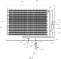
Fig. 1 is an alternative schematic view showing a phase-change electric water heater in an embodiment of the present disclosure; -
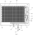
Fig. 2 is another alternative schematic view showing a phase-change electric water heater in an embodiment of the present disclosure; -
Fig. 3 is another alternative schematic view showing a phase-change electric water heater in an embodiment of the present disclosure. - a
liner 100; anaccommodating space 110; a phase-change material 120; acirculation pipeline 130; aninlet end 131 of thecirculation pipeline 130; anoutlet end 132 of thecirculation pipeline 130; asecond temperature sensor 140; anoutlet pipe 150; awater outlet 151; a third temperature sensor152; athermostatic valve 153; aninlet pipe 160; awater inlet 161; asecond flow sensor 162; a one-way relief valve 163; a one-way valve 170; apump 180; aheater 190; atemperature limiter 191; afirst flow sensor 192; afirst temperature sensor 193. - In order to make the object, technical solution and advantage of embodiments of the present application clearer, detailed and integral description will be made below to embodiments of the present disclosure with reference to drawings. Obviously, the described embodiments are some but not all embodiments of the present disclosure. Based on the described embodiments of the disclosure, other embodiments obtainable by those skilled in the art also belong to the scope of the present disclosure.
- In the specification, it should be understood that, the terms indicating orientation or position relationship such as "above", "below", "longitudinal", "horizontal", "top", "bottom", "inner" and "outer" should be construed to refer to the orientation or position relationship as then described or as shown in the drawings. These terms are merely for convenience and concision of description and do not alone indicate or imply that the device or element referred to must have a particular orientation or must be configured or operated in a particular orientation. Thus, it cannot be understood to limit the present disclosure. In addition, terms such as "first", "second" and "third" are used herein for purposes of description and are not intended to indicate or imply relative importance or significance or impliedly indicate quantity of the technical feature referred to. The term "upstream" and "downstream" refer to the direction of water flow.
- In the present disclosure, unless specified or limited otherwise, the terms "mounted", "connected", "coupled", "fixed" and the like are used broadly, and may be, for example, fixed connections, detachable connections, or integrated connections; may also be mechanical or electrical connections; may also be direct connections or indirect connections via intervening structures; may also be inner communications of two elements, which can be understood by those skilled in the art according to specific situations.
- In one aspect, the present disclosure provides in embodiment a phase-change electric water heater. Reference is made below to an alternative schematic view showing a phase-change electric water heater in an embodiment of the present disclosure in conjunction with
Figs. 1 to 3 . - As shown in
Figs. 1 to 3 , in embodiments, the phase-change electric water heater includes: acirculation pipeline 130; a phase-change material 120 for heat accumulation; and aliner 100, provided with an accommodating space therein, wherein the phase-change material and a portion of the circulation pipeline that is in contact with the phase-change material are arranged in the accommodating space. Theliner 100 is provided with the phase-change material 120, thus providing thermal insulation effect and preventing heat dissipation of the phase-change material 120. - According to the embodiment of the present disclosure, as shown in
Figs. 1 to 3 , the phase-change electric water heater further includes: aninlet pipe 160, connected to thecirculation pipeline 130 which is arranged inside the phase-change material 120 through aninlet end 131 of thecirculation pipeline 130; and anoutlet pipe 150, connected to thecirculation pipeline 130 which is arranged inside the phase-change material 120 through anoutlet end 132 of thecirculation pipeline 130. - According to the embodiment of the present disclosure, as shown in
Figs. 1 to 3 , theinlet end 131 or theoutlet end 132 of thecirculation pipeline 130 is provided with apump 180 and aheater 190. - According to an alternative implementation of the present disclosure, as shown in
Figs. 1 to 3 , at least oneheater 190 has an inlet connected to an outlet of thepump 180. - According to the embodiment of the present disclosure, as shown in
Figs. 1 to 3 , theinlet end 131 or theoutlet end 132 of thecirculation pipeline 130 is further provided with afirst flow sensor 192 for measuring a water flow in thecirculation pipeline 130. - According to the embodiment of the present disclosure, as shown in
Figs. 1 to 3 , theinlet end 131 or theoutlet end 132 of thecirculation pipeline 130 is further provided with afirst temperature sensor 193 for measuring a water temperature in thecirculation pipeline 130. - According to the embodiment of the present disclosure, as shown in
Figs. 1 to 3 , thefirst flow sensor 192 or thefirst temperature sensor 193 is arranged at a connecting pipe section between a water outlet of theheater 190 and the phase-change material 120. - According to an alternative implementation of the present disclosure, as shown in
Figs. 1 to 3 , thecirculation pipeline 130 is further provided with asecond temperature sensor 140 for measuring a temperature of the phase-change material 120. - According to an alternative implementation of the present disclosure, as shown in
Figs. 1 to 3 , theinlet pipe 160 is provided with asecond flow sensor 162 for measuring an inlet water flow in theinlet pipe 160. - According to an alternative implementation of the present disclosure, as shown in
Figs. 1 to 3 , theoutlet pipe 150 is connected to theoutlet end 132 of thecirculation pipeline 130 via athermostatic valve 153, and one end of theoutlet pipe 150 is connected to thethermostatic valve 153 and the other end serving as a water outlet. - According to an alternative implementation of the present disclosure, as shown in
Figs. 1 to 3 , thecirculation pipeline 130 is further provided with a first branch pipe, a three-way valve and a second branch pipe, a first end of the three-way valve is connected to theoutlet end 132 of thecirculation pipeline 130 via the first branch pipe; a second end of the three-way valve is connected to theinlet pipe 160 via the second branch pipe; and a third end of three-way valve is connected to theoutlet pipe 150; or the three-way valve connects theinlet end 131 and theoutlet end 132 of thecirculation pipeline 130, and one end of theoutlet pipe 150 is connected to the three-way valve, the other end serving as a water outlet. - According to an alternative implementation of the present disclosure, as shown in
Figs. 1 to 3 , theoutlet pipe 150 is further provided with athird temperature sensor 152 for measuring an outlet water temperature in theoutlet pipe 150. - According to an alternative implementation of the present disclosure, as shown in
Figs. 1 to 3 , the phase-change electric water heater further includes a one-way valve 170 arranged at thecirculation pipeline 130 and configured to connect theoutlet end 132 and theinlet end 131 of thecirculation pipeline 130. - According to an alternative implementation of the present disclosure, as shown in
Figs. 1 to 3 , the phase-change electric water heater further includes atemperature limiter 191 arranged at theheater 190 to limit a highest heating temperature. - According to an alternative implementation of the present disclosure, as shown in
Figs. 1 to 3 , the phase-change electric water heater further includes a one-way relief valve 163 arranged at theinlet pipe 160, wherein the one-way relief valve 163 is spaced apart from and located upstream of thesecond flow sensor 162.Figs. 1 to 3 exemplify the one-way relief valve 163 arranged at theinlet pipe 160, thereby avoiding water in thecirculation pipeline 130 from backflow to thewater inlet 161. - In the present embodiment, the phase-
change material 120 is used for heat accumulation or dissipation. In specific, heat exchange occurs between the phase-change material 120 and the heated water in thecirculation pipeline 130, thus heat from the water in thecirculation pipeline 130 is stored. The phase-change material 120 may also dissipate the saved heat to the water in thecirculation pipeline 130, such that the water discharged from theoutlet pipe 150 can meet supply demand. One end of theinlet pipe 160 is connected to thecirculation pipeline 130 and the other end serving as awater inlet 161, which may be connected to a water source device outside the phase-change electric water heater. For example, thewater inlet 161 may be connected to a user's tap water pipe. One end of Theoutlet pipe 150 connected to a three-way valve and the other end serving as awater outlet 151, which may be connected to a shower in a bathroom. An outlet water temperature of theheater 190 and the temperature of the phase-change material 120 are monitored by afirst temperature sensor 193 and asecond temperature sensor 140, respectively, thereby avoiding an over-high local water temperature or dry-burning, and thus guaranteeing a constant outlet water temperature. - It would be understood that, in order to improve heat exchange efficacy, a contacting area between the
circulation pipeline 130 and the phase-change material 120 is increased; the portion of thecirculation pipeline 130 that is in contact with the phase-change material 120 is arranged in a spiral or serpentine shape; and the portion of thecirculation pipeline 130 that is in contact with the phase-change material 120 may be arranged in parallel or in series.Fig. 1 exemplifies the portion of thecirculation pipeline 130 that is in contact with the phase-change material 120 is arranged in a serpentine shape, and the water in thecirculation pipeline 130 flows in a counterclockwise circulating direction. The three-way vale has a first end (the left end of the three-way valve as shown inFigs. 1-3 ) serving as a hot end; a second end (the right end of the three-way valve as shown inFigs. 1-3 ) serving as a cold end; and a third end (the bottom end of the three-way valve as shown inFigs. 1-3 ) serving as an outlet end. The outlet water temperature can be controlled by adjusting respective opening degrees of the cold end and the hot end of the three-way valve, thereby improving the constant effect of the outlet water temperature. In specific, the three-way valve may be athermostatic valve 153. - As an example to carry out the present disclosure, the present disclosure provides in embodiment a phase-change electric water heater. Reference is made below to an alternative schematic view showing a phase-change electric water heater in an embodiment of the present disclosure in conjunction with
Figs. 1 to 3 . - As shown in
Figs. 1 to 3 , in embodiments, the phase-change electric water heater includes: a circulation pipeline and a phase-change material for heat accumulation; wherein at least one side of the circulation pipeline 130 is arranged to be adherent to the phase-change material 120, an inlet end 131 of the circulation pipeline 130 is provided sequentially with a pump 180, a heater 190, a first flow sensor 192 for measuring an outlet water flow of the heater 190 and a first temperature sensor 193 for measuring an outlet water temperature of the heater 190 (as shown inFigs. 1 and2 ); alternatively, an outlet end 132 of the circulation pipeline 130 is provided sequentially with a pump 180, a heater 190, a first flow sensor 192 for measuring an outlet water flow of the heater 190 and a first temperature sensor 193 for measuring an outlet water temperature of the heater 190 (as shown inFig. 3 ); an inlet of the heater 190 is connected to an outlet of the pump 180; the outlet end 132 of the circulation pipeline 130 is provided with a second temperature sensor 140 for measuring a temperature of the phase-change material 120; the inlet end 131 of the circulation pipeline 130 is further provided with an inlet pipe 160, and the inlet pipe 160 is provided with a second flow sensor 162 for measuring an inlet water flow in the inlet pipe 160; the outlet end 132 of the circulation pipeline 130 is further provided with a first branch pipe, a three-way valve, an outlet pipe 150 and a second branch pipe; a first end of the three-way valve is connected to the outlet end 132 of the circulation pipeline 130 via the first branch pipe; a second end of the three-way valve is connected to the inlet pipe 160 via the second branch pipe; and a third end of three-way valve is connected to the outlet pipe 150 (as shown inFig. 1 ); alternatively, the circulation pipeline 130 is further provided with a three-way valve and an outlet pipe 150, the three-way valve connects the inlet end 131 and the outlet end 132 of the circulation pipeline 130, one end of the outlet pipe 150 is connected to the three-way valve, and the other end serving as a water outlet (as shown inFigs. 2 and3 ); the outlet pipe 150 is further provided with a third temperature sensor 152 for measuring an outlet water temperature in the outlet pipe 150. - In the present embodiment, the phase-
change material 120 is used for heat accumulation or dissipation. In specific, heat exchange occurs between the phase-change material 120 and the heated water in thecirculation pipeline 130, thus heat from the water in thecirculation pipeline 130 is stored. The phase-change material 120 may also dissipate the saved heat to the water in thecirculation pipeline 130, such that the water discharged from theoutlet pipe 150 can meet supply demand. One end of theinlet pipe 160 connected to thecirculation pipeline 130 and the other end serving as awater inlet 161, which may be connected to a water source device outside the phase-change electric water heater. For example, thewater inlet 161 may be connected to a user's tap water pipe. One end of theoutlet pipe 150 is connected to a three-way valve and the other end serving as awater outlet 151, which may be connected to a shower in a bathroom. An outlet water temperature of theheater 190 and the temperature of the phase-change material 120 are monitored by afirst temperature sensor 193 and asecond temperature sensor 140 respectively, thereby avoiding an over-high local water temperature or dry-burning, and thus guaranteeing a constant outlet water temperature. - It would be understood that, in order to improve heat exchange efficacy, a contacting area between the
circulation pipeline 130 and the phase-change material 120 is increased; the portion of thecirculation pipeline 130 that is in contact with the phase-change material 120 is arranged in a spiral or serpentine shape; and the portion of thecirculation pipeline 130 that is in contact with the phase-change material 120 may be arranged in parallel or in series.Fig. 1 exemplifies the portion of thecirculation pipeline 130 that is in contact with the phase-change material 120 is arranged in a serpentine shape, and water in thecirculation pipeline 130 flows in a counterclockwise circulating direction. The three-way vale has a first end (the left end of the three-way valve as shown inFigs. 1-3 ) serving as a hot end; a second end (the right end of the three-way valve as shown inFigs. 1-3 ) serving as a cold end; and a third end (the bottom end of the three-way valve as shown inFigs. 1-3 ) serving as an outlet end. The outlet water temperature can be controlled by adjusting respective opening degrees of the cold end and the hot end of the three-way valve, thereby improving the constant effect of the outlet water temperature. In specific, the three-way valve may be athermostatic valve 153. - In an alternative implementation of the present disclosure, as shown in
Fig. 1 , the phase-change electric water heater further includes a one-way valve 170 arranged at thecirculation pipeline 130 and configured to connect theoutlet end 132 and theinlet end 131 of thecirculation pipeline 130. The one-way valve 170 only allows water to flow from theoutlet end 132 of thecirculation pipeline 130 to theinlet end 131 of thecirculation pipeline 130, but forbids water to flow in the reverse direction, thereby ensuring that cold water flows towards theheater 190 after entering thecirculation pipeline 130. - According to an alternative implementation of the present disclosure, as shown in
Figs. 1 to 3 , the phase-change electric water heater further includes atemperature limiter 191 arranged at theheater 190 to limit a highest heating temperature. Theheater 190 is provided with thetemperature limiter 191, such that it is possible to prevent water evaporation due to over-high temperature during heating, thereby avoiding the water temperature from being over-high and thus improving the constant temperature effect. - According to an alternative implementation of the present disclosure, as shown in
Figs. 1 to 3 , the phase-change electric water heater further includes a one-way relief valve 163 arranged at theinlet pipe 160, wherein the one-way relief valve 163 is spaced apart from and located upstream of thesecond flow sensor 162.Figs. 1 to 3 exemplify the one-way relief valve 163 arranged at theinlet pipe 160, thereby avoiding water in thecirculation pipeline 130 from backflow to thewater inlet 161. - According to an alternative implementation of the present disclosure, as shown in
Figs. 1 to 3 , the phase-change electric water heater further includes aliner 100 provided with anaccommodating space 110 therein, wherein the phase-change material 120 and a portion of thecirculation pipeline 130 that is in contact with the phase-change material 120 are arranged in the accommodating space. Theliner 100 is provided with the phase-change material 120, thus providing the thermal insulation effect and preventing heat dissipation of the phase-change material 120. - In still another aspect, the present disclosure provides in embodiments a water temperature control method, controlling the phase-change electric water heater as described in the aforementioned embodiments. The water temperature control method includes: turning off an
inlet pipe 160, turning on apump 180 and turning on aheater 190; driving, by thepump 180, water in acirculation pipeline 130 to flow into theheater 190 for heating; allowing heated water to flow into a portion of thecirculation pipeline 130 that is arranged in a phase-change material 120; allowing heat exchange to occur between the phase-change material 120 and the heated water in thecirculation pipeline 130; and turning off thepump 180 and turning off theheater 190 to stop working. - In an alternative implementation of the present disclosure, the water temperature control method further includes: detecting a temperature of the phase-
change material 120, and turning on thepump 180 and turning on theheater 190 for heating when the temperature of the phase-change material 120 is lower than a first threshold temperature. - In an alternative implementation of the present disclosure, the water temperature control method further includes: detecting a temperature of the phase-
change material 120, and turning off thepump 180 and turning off theheater 190 to stop heating when the temperature of the phase-change material 120 is lower than a second threshold temperature. - In an alternative implementation of the present disclosure, the water temperature control method further includes: turning on an
inlet pipe 160 and turning on anoutlet pipe 150; detecting an outlet water temperature of theoutlet pipe 150; adjusting an opening degree of a hot end of a three-way valve which is connected to anoutlet end 132 of thecirculation pipeline 130 and an opening degree of a cold end of the three-way valve which is connected to aninlet end 131 of thecirculation pipeline 130, when a difference between the outlet water temperature of theoutlet pipe 150 and a second threshold temperature is out of a preset range; and controlling water to be discharged from theoutlet pipe 150 when athird temperature sensor 152 measures that the difference between the outlet water temperature of theoutlet pipe 150 and the second threshold temperature stays within the preset range. - In an alternative implementation of the present disclosure, the water temperature control method further includes: turning on the
pump 180 to drive water flow to theheater 190; and turning off thepump 180 to stop driving when afirst flow sensor 192 measures that an outlet water flow of theheater 190 is lower than a preset threshold. - In an alternative implementation of the present disclosure, the water temperature control method further includes: turning on an
inlet pipe 160; and turning off a cold end of a three-way valve which is connected to aninlet end 131 of thecirculation pipeline 130 when water flows from theinlet pipe 160 to thecirculation pipeline 130 for the first time. - In an alternative implementation of the present disclosure, the water temperature control method further includes: detecting an outlet water temperature of the
heater 190 when theinlet pipe 160 is turned off; and turning off thepump 180 to stop driving and turning off theheater 190 to stop working when the outlet water temperature of theheater 190 achieves a third threshold temperature. - In an alternative implementation of the present disclosure, the water temperature control method further includes: turning on an
inlet pipe 160 to allow water to flow from theinlet pipe 160 into theheater 190 through aninlet end 131 of thecirculation pipeline 130; turning on theheater 190 when an outlet water temperature of theheater 190 is lower than a fourth threshold temperature; heating, by theheater 190, the water entering theheater 190 and detecting the outlet water temperature of theheater 190; and turning off theheater 190 to stop working when the outlet water temperature of theheater 190 achieves the fourth threshold temperature. - In an alternative implementation of the present disclosure, the water temperature control method further includes: turning on an
inlet pipe 160 and anoutlet pipe 150; detecting an outlet water temperature of theoutlet pipe 150; when a difference between the outlet water temperature of the outlet pipe (150) and a second threshold temperature is out of a preset range, adjusting athermostatic valve 153 to allow the difference between the outlet water temperature of theoutlet pipe 150 and the second threshold temperature stays within the preset range; and controlling water to be discharged from theoutlet pipe 150. - In still another aspect, the present disclosure provides in embodiments a water temperature control method, controlling the phase-change electric water heater as described in the aforementioned embodiments. The water temperature control method includes: turning on a
pump 180 and turning on aheater 190 when aninlet pipe 160 is turned off and asecond temperature sensor 140 measures that a temperature of a phase-change material 120 is lower than a first threshold temperature; driving, by thepump 180, water in acirculation pipeline 130 to flow in a direction from theoutlet end 132 to theinlet end 131 of thecirculation pipeline 130; allowing water to flow into theheater 190 for heating; allowing heated water to flow into thecirculation pipeline 130 again from theinlet end 131 of thecirculation pipeline 130, allowing heat exchange to occur between the phase-change material 120 and the heated water in thecirculation pipeline 130; and turning off thepump 180 to stop driving and turning off theheater 190 to stop working when thesecond temperature sensor 140 measures that the temperature of the phase-change material 120 achieves the first threshold temperature. - In the present embodiment, the
pump 180 is turned on when theinlet pipe 160 is turned off and thesecond temperature sensor 140 measures that the temperature of the phase-change material 120 is lower than the first threshold temperature. Thepump 180 may be turned on after the temperature of the phase-change material 120 is lower than the first threshold temperature for a certain temperature range. For example, thepump 180 is turned on when the temperature of the phase-change material 120 is -5°C lower than the first threshold temperature. The temperature of the phase-change material 120 may be a temperature of the phase-change material 120 itself, or may be a temperature of water in the portion of thecirculation pipeline 130 that is in contact with the phase-change material 120. Thefirst temperature sensor 193 measures an outlet water temperature of theheater 190 in real time. Theheater 190 is turned on within a first preset duration, e.g., 6s, 10s, 12s or 15s, when thefirst temperature sensor 193 measures that the outlet water temperature of theheater 190 is less than a third threshold temperature, for example when thefirst temperature sensor 193 measures that the outlet water temperature of theheater 190 is less than 88°C, 90°C, 91°C, 93°C, 95°C or 98°C. Thepump 180 drives water in thecirculation pipeline 130 to flow in a direction from theoutlet end 132 to theinlet end 131 of thecirculation pipeline 130; water is then allowed to flow into theheater 190 for heating; heated water is then allowed to flow into thecirculation pipeline 130 again from theinlet end 131 of thecirculation pipeline 130; heat exchange is allowed to occur between the phase-change material 120 and the heated water in thecirculation pipeline 130; and thepump 180 is turned off to stop driving and theheater 190 is turned off to stop working when thesecond temperature sensor 140 measures that the temperature of the phase-change material 120 achieves the first threshold temperature. In specific, theheater 190 is turned off, e.g., by cutting off power supply for theheater 190, when the temperature of the phase-change material 120 is equal to or greater than the first threshold temperature. The pump may continue working for a second preset duration, e.g., 20s, 30s, 40s or 45s, till turned off. The above control mode is the working mode of the phase-change electric water heater when theinlet pipe 160 is turned off, i.e., thesecond flow sensor 162 detects that the inlet water flow of theinlet pipe 160 is zero. - When the
inlet pipe 160 is turned on, i.e., a water flow exists in theinlet pipe 160, and thepump 180 is not in operation, the working mode of the phase-change electric water heater includes: turning on theheater 190 when thefirst flow sensor 192 measures an outlet water flow of theheater 190 is greater than a preset flow and thefirst temperature sensor 193 measures that an outlet water temperature of theheater 190 is greater than a fourth threshold temperature, for example, when thefirst flow sensor 192 measures the outlet water flow of theheater 190 is greater than 2 L/min, 3 L/ min or 5 L/ min and thefirst temperature sensor 193 measures that the outlet water temperature of theheater 190 is greater than 88°C, 90°C, 91°C, 93°C, 95°C or 98°C; otherwise allowing theheater 190 not to heat. The fourth threshold temperature may be equal to the first threshold temperature. - In an alternative implementation of the present disclosure, the water temperature control method further includes: adjusting an opening degree of a hot end of a three-way valve which is connected to an
outlet end 132 of thecirculation pipeline 130 and an opening degree of a cold end of the three-way valve which is connected to aninlet end 131 of thecirculation pipeline 130, when athird temperature sensor 152 measures that a difference between an outlet water temperature of anoutlet pipe 150 and a second threshold temperature is out of a preset range; and controlling water to be discharged from theoutlet pipe 150 when thethird temperature sensor 152 measures that the difference between the outlet water temperature of theoutlet pipe 150 and the second threshold temperature stays within the preset range. - In specific, the
third temperature sensor 152 may be arranged at one end of theoutlet pipe 150 which is connected to the three-way valve, that is, a temperature of theoutlet pipe 150 detected by thethird temperature sensor 152 refers to a water temperature at an outlet end of the three-way valve. The three-way valve may be connected to an electric motor such that the respective opening degrees of the cold end and the hot end of the three-way valve may be controlled by the electric motor. A preset range for a difference between an outlet water temperature of the three-way valve and the fourth threshold temperature may be set as 0 to 2°C, 0 to 3°C, 0 to 4°C or 0 to 5°C. Taking the preset range being 0 to 2°C as an example, the opening degree of the hot end of the three-way vale is decreased and the opening degree of the cold end of the three-way vale is increased by the electric motor, when the outlet water temperature of theoutlet pipe 150, e.g., the outlet water temperature of the three-way valve, is 2°C or more greater than the fourth preset temperature. The opening degree of the hot end of the three-way vale is increased and the opening degree of the cold end of the three-way vale is decreased by the electric motor, when the outlet water temperature of the three-way valve is 2°C or more greater than the fourth preset temperature. Theoutlet pipe 150 is controlled to discharge water when the difference between the outlet water temperature of the three-way valve and the fourth preset temperature is within 2°C by continuous measuring and adjusting. - In an alternative implementation of the present disclosure, the water temperature control method further includes: turning on the
pump 180; driving, by thepump 180, water to flow towards theheater 190; and turning off thepump 180 to stop driving when thefirst flow sensor 192 measures that the outlet water flow of theheater 190 is lower than a preset threshold. - For example, after the
pump 180 is turned on to drive water flow towards theheater 190, when thefirst flow sensor 192 measures that an outlet water flow of theheater 190 is 0 L/min, or below 0.1 L/min or 0.5 L/min, thepump 180 is turned off to stop driving. If thefirst flow sensor 192 measures that the outlet water flow of theheater 190 is not 0 L/min, or not below 0.1 L/min or 0.5 L/min, thepump 180 continues working. - In an alternative implementation of the present disclosure, the water temperature control method further includes: turning on the
inlet pipe 160; and turning off the cold end of the three-way valve which is connected to theinlet end 131 of thecirculation pipeline 130 when water flows from theinlet pipe 160 to thecirculation pipeline 130 for the first time. It would be appreciated that when the phase-change electric water heater is used for the first time, it needs to be watered at first to ensure that there is water in thecirculation pipeline 130. - In an alternative implementation of the present disclosure, the water temperature control method further includes: turning off the
pump 180 to stop driving and turning off theheater 190 to stop working when theinlet pipe 160 is turned off and thefirst temperature sensor 193 measures that an outlet water temperature of theheater 190 achieves the third temperature threshold. - In an alternative implementation of the present disclosure, the water temperature control method further includes: turning on the
inlet pipe 160, allowing water to flow from theinlet pipe 160 into theheater 190 via theinlet end 131 of thecirculation pipeline 130; turning on theheater 190 when thefirst temperature sensor 193 measures that the outlet water temperature of theheater 190 is less than the fourth temperature threshold; heating, by theheater 190, water entering theheater 190; and turning off theheater 190 to stop working when thefirst temperature sensor 193 measures that the outlet water temperature of theheater 190 achieves the fourth temperature threshold. - Other structures and operations of the phase-change electric water heater according to embodiments of the present disclosure are understandable and easy to implement for those skilled in the art, and therefore will not be described in detail.
- The above are only preferred embodiments of the present disclosure, and are not used to limit the scope of the present disclosure.
Claims (13)
- A phase-change electric water heater, comprising:a circulation pipeline (130);a phase-change material (120) for heat accumulation; anda liner (100), provided with an accommodating space (110) therein,wherein the phase-change material (120) and a portion of the circulation pipeline (130) that is in contact with the phase-change material (120) are arranged in the accommodating space (110);wherein an inlet end (131) or an outlet end (132) of the circulation pipeline (130) is provided with a pump (180) and a heater (190),characterized in thatwherein the inlet end (131) or the outlet end (132) of the circulation pipeline (130) is further provided with a first flow sensor (192) for measuring a water flow in the circulation pipeline (130), andwherein the inlet end (131) or the outlet end (132) of the circulation pipeline (130) is further provided with a first temperature sensor (193) for measuring a water temperature in the circulation pipeline (130), wherein the first flow sensor (192) or the first temperature sensor (193) is arranged at a connecting pipe section of the circulation pipeline (130) between the water outlet (151) of the heater (190) and the phase-change material (120).
- The phase-change electric water heater according to claim 1, further comprising:an inlet pipe (160), connected to the circulation pipeline (130) which is arranged inside the phase-change material (120) through an inlet end (131) of the circulation pipeline (130); andan outlet pipe (150), connected to the circulation pipeline (130) which is arranged inside the phase-change material (120) through an outlet end (132) of the circulation pipeline (130).
- The phase-change electric water heater according to claim 1 or 2, wherein at least one heater (190) has an inlet connected to an outlet of the pump (180).
- The phase-change electric water heater according to any one of claims 1 to 3, wherein the circulation pipeline (130) is further provided with a second temperature sensor (140) for measuring a temperature of the phase-change material (120).
- The phase-change electric water heater according to any one of claims 2 to 4, wherein the inlet pipe (160) is provided with a second flow sensor (162) for measuring an inlet water flow in the inlet pipe (160),
and/or,
wherein the outlet pipe (150) is connected to the outlet end (132) of the circulation pipeline (130) via a thermostatic valve (153), and one end of the outlet pipe (150) is connected to the thermostatic valve (153) and the other end serving as a water outlet (151). - The phase-change electric water heater according to any one of claims 1 to 5, whereinthe circulation pipeline (130) is further provided with a first branch pipe, a three-way valve and a second branch pipe,a first end of the three-way valve is connected to the outlet end (132) of the circulation pipeline (130) via the first branch pipe; a second end of the three-way valve is connected to the inlet pipe (160) via the second branch pipe; and a third end of the three-way valve is connected to the outlet pipe (150); orthe three-way valve connects the inlet end (131) and the outlet end (132) of the circulation pipeline (130), and one end of the outlet pipe (150) is connected to the three-way valve, the other end serving as a water outlet (151).
- The phase-change electric water heater according to any one of claims 2 to 6, wherein the outlet pipe (150) is further provided with a third temperature sensor (152) for measuring an outlet water temperature in the outlet pipe (150).
- The phase-change electric water heater according to any one of claims 1 to 7, further comprising a one-way valve (170) arranged at the circulation pipeline (130) and configured to connect an outlet end (132) and an inlet end (131) of the circulation pipeline (130),
and/or,further comprising a temperature limiter (191) arranged at the heater (190) to limit a highest heating temperature,
and/or,further comprising a one-way relief valve (163) arranged at the inlet pipe (160), wherein the one-way relief valve (163) is spaced apart from and located upstream of the second flow sensor (162). - A water temperature control method, for controlling a phase-change electric water heater as defined in any one of claims 1 to 8, wherein the water temperature control method comprises:turning off an inlet pipe (160), turning on a pump (180) and turning on a heater (190);driving, by the pump (180), water in a circulation pipeline (130) to flow into the heater (190) for heating;allowing heated water to flow into a portion of the circulation pipeline (130) that is arranged in a phase-change material (120);allowing heat exchange to occur between the phase-change material (120) and the heated water in the circulation pipeline (130); andturning off the pump (180) and turning off the heater (190) to stop working.
- The water temperature control method according claim 9, further comprising:detecting a temperature of the phase-change material (120), andturning on the pump (180) and turning on the heater (190) for heating when the temperature of the phase-change material (120) is lower than a first threshold temperature,
and/or,further comprising:detecting a temperature of the phase-change material (120), andturning off the pump (180) and turning off the heater (190) to stop heating when the temperature of the phase-change material (120) is lower than a second threshold temperature. - The water temperature control method according claim 9 or 10, further comprising:turning on the inlet pipe (160) and an outlet pipe (150);detecting an outlet water temperature of the outlet pipe (150);adjusting an opening degree of a hot end of a three-way valve which is connected to an outlet end (132) of the circulation pipeline (130) and an opening degree of a cold end of the three-way valve which is connected to an inlet end (131) of the circulation pipeline (130), when a difference between the outlet water temperature of the outlet pipe (150) and a second threshold temperature is out of a preset range; andcontrolling water to be discharged from, the outlet pipe (150) when a third temperature sensor (152) measures that the difference between the outlet water temperature of the outlet pipe (150) and the second threshold temperature is within the preset range,
and/or,further comprising:turning on the pump (180) to drive water flow towards the heater (190); andturning off the pump (180) to stop driving when a first flow sensor (192) measures that an outlet water flow of the heater (190) is lower than a preset threshold. - The water temperature control method according any one of claims 9 to 11, further comprising:turning on the inlet pipe (160); andturning off a cold end of a three-way valve which is connected to an inlet end (131) of the circulation pipeline (130) when water flows from the inlet pipe (160) to the circulation pipeline (130) for the first time,
and/or,further comprising:detecting an outlet water temperature of the heater (190) when the inlet pipe (160) is turned off; andturning off the pump (180) to stop driving and turning off the heater (190) to stop working when the outlet water temperature of the heater (190) achieves a third threshold temperature. - The water temperature control method according any one of claims 9 to 12, further comprising:turning on the inlet pipe (160) to allow water to flow from the inlet pipe (160) into the heater (190) through an inlet end (131) of the circulation pipeline (130);turning on the heater (190) when an outlet water temperature of the heater (190) is lower than a fourth threshold temperature;heating, by the heater (190), the water entering the heater (190) and detecting the outlet water temperature of the heater (190); andturning off the heater (190) to stop working when the outlet water temperature of the heater (190) achieves the fourth threshold temperature,
and/or,further comprising:turning on the inlet pipe (160) and an outlet pipe (150);detecting an outlet water temperature of the outlet pipe (150);when a difference between the outlet water temperature of the outlet pipe (150) and the second threshold temperature is out of a preset range, adjusting a thermostatic valve (153) to allow the difference between the outlet water temperature of the outlet pipe (150) and a second threshold temperature stays within the preset range; andcontrolling the water to be discharged from the outlet pipe (150).
Applications Claiming Priority (5)
| Application Number | Priority Date | Filing Date | Title |
|---|---|---|---|
| CN201810260304.XA CN108278778A (en) | 2018-03-27 | 2018-03-27 | A kind of phase transformation electric heater and temperature control method of water |
| CN201810259828.7A CN108489099A (en) | 2018-03-27 | 2018-03-27 | A kind of phase transformation electric heater and temperature control method of water |
| CN201820424639.6U CN208312701U (en) | 2018-03-27 | 2018-03-27 | A kind of phase transformation electric heater |
| CN201820424736.5U CN208312702U (en) | 2018-03-27 | 2018-03-27 | A kind of phase transformation electric heater |
| PCT/CN2019/079952 WO2019184961A1 (en) | 2018-03-27 | 2019-03-27 | Phase-change electric water heater and water temperature control method |
Publications (3)
| Publication Number | Publication Date |
|---|---|
| EP3757478A1 EP3757478A1 (en) | 2020-12-30 |
| EP3757478A4 EP3757478A4 (en) | 2021-05-26 |
| EP3757478B1 true EP3757478B1 (en) | 2024-03-27 |
Family
ID=68060890
Family Applications (1)
| Application Number | Title | Priority Date | Filing Date |
|---|---|---|---|
| EP19776346.9A Active EP3757478B1 (en) | 2018-03-27 | 2019-03-27 | Phase-change electric water heater and water temperature control method |
Country Status (2)
| Country | Link |
|---|---|
| EP (1) | EP3757478B1 (en) |
| WO (1) | WO2019184961A1 (en) |
Family Cites Families (13)
| Publication number | Priority date | Publication date | Assignee | Title |
|---|---|---|---|---|
| CN101737843A (en) * | 2008-11-21 | 2010-06-16 | 刘军 | Phase-change heat storage can |
| CN202581799U (en) * | 2012-05-10 | 2012-12-05 | 江苏启能新能源材料有限公司 | Phase-change thermal-storage type electric water heater |
| CN102654308A (en) * | 2012-05-10 | 2012-09-05 | 江苏启能新能源材料有限公司 | Phase-change heat storage type electric water heater |
| CN104976765B (en) * | 2015-07-31 | 2018-08-07 | 江苏启能新能源材料有限公司 | A kind of phase-change heat storage type electric water heater |
| CN205137918U (en) * | 2015-10-22 | 2016-04-06 | 江苏启能新能源材料有限公司 | Phase -change thermal -storage type electric water heater |
| CN205717913U (en) * | 2016-04-25 | 2016-11-23 | 芜湖美的厨卫电器制造有限公司 | Phase-change heat-storage water heater |
| CN106196604A (en) * | 2016-07-28 | 2016-12-07 | 芜湖美的厨卫电器制造有限公司 | Phase-change thermal storage type water heater and control method thereof |
| CN208382572U (en) * | 2018-01-25 | 2019-01-15 | 芜湖美的厨卫电器制造有限公司 | Phase-change thermal storage type water heater |
| CN108489099A (en) * | 2018-03-27 | 2018-09-04 | 芜湖美的厨卫电器制造有限公司 | A kind of phase transformation electric heater and temperature control method of water |
| CN208312700U (en) * | 2018-03-27 | 2019-01-01 | 芜湖美的厨卫电器制造有限公司 | A kind of phase transformation electric heater |
| CN208312701U (en) * | 2018-03-27 | 2019-01-01 | 芜湖美的厨卫电器制造有限公司 | A kind of phase transformation electric heater |
| CN208312702U (en) * | 2018-03-27 | 2019-01-01 | 芜湖美的厨卫电器制造有限公司 | A kind of phase transformation electric heater |
| CN108278778A (en) * | 2018-03-27 | 2018-07-13 | 芜湖美的厨卫电器制造有限公司 | A kind of phase transformation electric heater and temperature control method of water |
-
2019
- 2019-03-27 WO PCT/CN2019/079952 patent/WO2019184961A1/en unknown
- 2019-03-27 EP EP19776346.9A patent/EP3757478B1/en active Active
Also Published As
| Publication number | Publication date |
|---|---|
| WO2019184961A1 (en) | 2019-10-03 |
| EP3757478A1 (en) | 2020-12-30 |
| EP3757478A4 (en) | 2021-05-26 |
Similar Documents
| Publication | Publication Date | Title |
|---|---|---|
| CA2751072C (en) | Apparatus and control method for a hybrid tankless water heater | |
| KR101559185B1 (en) | Heat pump water heater | |
| JP5462009B2 (en) | Solar water heating system | |
| CN108278778A (en) | A kind of phase transformation electric heater and temperature control method of water | |
| JP5537971B2 (en) | Solar water heating system | |
| EP3757478B1 (en) | Phase-change electric water heater and water temperature control method | |
| JP4981777B2 (en) | Solar water heater | |
| CN208312701U (en) | A kind of phase transformation electric heater | |
| JP3976319B2 (en) | Water heater | |
| CN214949876U (en) | Constant temperature control device of solar water heating system | |
| JP5866217B2 (en) | Water heater | |
| JP5546264B2 (en) | Solar water heater | |
| JP4052200B2 (en) | Hot water storage hot water supply system | |
| JP2004150688A (en) | Storage electric water heater | |
| CN105520627B (en) | Dual-purpose electric kettle is stored up soon | |
| CN207945816U (en) | Prevent out the water heater of cold water | |
| JP2006349273A (en) | Water heater | |
| JP2006308178A (en) | Hot-water supplier | |
| JP3869426B2 (en) | Hot water storage water heater | |
| JP4383238B2 (en) | Water heater | |
| JP2008008563A (en) | Storage type hot-water supply method and storage type hot-water supply device | |
| CN219283626U (en) | Heat exchange system and gas water heater | |
| CN219037105U (en) | Multi-point temperature-controlled water heater | |
| CN212132636U (en) | Domestic hot water circulating device | |
| JP4070627B2 (en) | Multi-function water heater |
Legal Events
| Date | Code | Title | Description |
|---|---|---|---|
| STAA | Information on the status of an ep patent application or granted ep patent |
Free format text: STATUS: THE INTERNATIONAL PUBLICATION HAS BEEN MADE |
|
| PUAI | Public reference made under article 153(3) epc to a published international application that has entered the european phase |
Free format text: ORIGINAL CODE: 0009012 |
|
| STAA | Information on the status of an ep patent application or granted ep patent |
Free format text: STATUS: REQUEST FOR EXAMINATION WAS MADE |
|
| 17P | Request for examination filed |
Effective date: 20200925 |
|
| AK | Designated contracting states |
Kind code of ref document: A1 Designated state(s): AL AT BE BG CH CY CZ DE DK EE ES FI FR GB GR HR HU IE IS IT LI LT LU LV MC MK MT NL NO PL PT RO RS SE SI SK SM TR |
|
| AX | Request for extension of the european patent |
Extension state: BA ME |
|
| A4 | Supplementary search report drawn up and despatched |
Effective date: 20210428 |
|
| RIC1 | Information provided on ipc code assigned before grant |
Ipc: F24H 7/02 20060101AFI20210421BHEP Ipc: F24H 9/18 20060101ALI20210421BHEP Ipc: F24H 9/20 20060101ALI20210421BHEP Ipc: F24H 9/12 20060101ALI20210421BHEP Ipc: F28D 20/02 20060101ALI20210421BHEP |
|
| DAV | Request for validation of the european patent (deleted) | ||
| DAX | Request for extension of the european patent (deleted) | ||
| GRAP | Despatch of communication of intention to grant a patent |
Free format text: ORIGINAL CODE: EPIDOSNIGR1 |
|
| STAA | Information on the status of an ep patent application or granted ep patent |
Free format text: STATUS: GRANT OF PATENT IS INTENDED |
|
| INTG | Intention to grant announced |
Effective date: 20240115 |
|
| GRAS | Grant fee paid |
Free format text: ORIGINAL CODE: EPIDOSNIGR3 |
|
| GRAA | (expected) grant |
Free format text: ORIGINAL CODE: 0009210 |
|
| STAA | Information on the status of an ep patent application or granted ep patent |
Free format text: STATUS: THE PATENT HAS BEEN GRANTED |
|
| AK | Designated contracting states |
Kind code of ref document: B1 Designated state(s): AL AT BE BG CH CY CZ DE DK EE ES FI FR GB GR HR HU IE IS IT LI LT LU LV MC MK MT NL NO PL PT RO RS SE SI SK SM TR |
|
| REG | Reference to a national code |
Ref country code: GB Ref legal event code: FG4D |
|
| REG | Reference to a national code |
Ref country code: CH Ref legal event code: EP |
|
| REG | Reference to a national code |
Ref country code: DE Ref legal event code: R096 Ref document number: 602019049073 Country of ref document: DE |