EP3757416A1 - Schaltbare getriebeanordnung - Google Patents
Schaltbare getriebeanordnung Download PDFInfo
- Publication number
- EP3757416A1 EP3757416A1 EP20174870.4A EP20174870A EP3757416A1 EP 3757416 A1 EP3757416 A1 EP 3757416A1 EP 20174870 A EP20174870 A EP 20174870A EP 3757416 A1 EP3757416 A1 EP 3757416A1
- Authority
- EP
- European Patent Office
- Prior art keywords
- sleeve
- guide
- transmission arrangement
- arrangement according
- shift
- Prior art date
- Legal status (The legal status is an assumption and is not a legal conclusion. Google has not performed a legal analysis and makes no representation as to the accuracy of the status listed.)
- Granted
Links
Images


Classifications
-
- F—MECHANICAL ENGINEERING; LIGHTING; HEATING; WEAPONS; BLASTING
- F16—ENGINEERING ELEMENTS AND UNITS; GENERAL MEASURES FOR PRODUCING AND MAINTAINING EFFECTIVE FUNCTIONING OF MACHINES OR INSTALLATIONS; THERMAL INSULATION IN GENERAL
- F16D—COUPLINGS FOR TRANSMITTING ROTATION; CLUTCHES; BRAKES
- F16D28/00—Electrically-actuated clutches
-
- F—MECHANICAL ENGINEERING; LIGHTING; HEATING; WEAPONS; BLASTING
- F16—ENGINEERING ELEMENTS AND UNITS; GENERAL MEASURES FOR PRODUCING AND MAINTAINING EFFECTIVE FUNCTIONING OF MACHINES OR INSTALLATIONS; THERMAL INSULATION IN GENERAL
- F16H—GEARING
- F16H63/00—Control outputs from the control unit to change-speed- or reversing-gearings for conveying rotary motion or to other devices than the final output mechanism
- F16H63/02—Final output mechanisms therefor; Actuating means for the final output mechanisms
- F16H63/08—Multiple final output mechanisms being moved by a single common final actuating mechanism
- F16H63/16—Multiple final output mechanisms being moved by a single common final actuating mechanism the final output mechanisms being successively actuated by progressive movement of the final actuating mechanism
-
- F—MECHANICAL ENGINEERING; LIGHTING; HEATING; WEAPONS; BLASTING
- F16—ENGINEERING ELEMENTS AND UNITS; GENERAL MEASURES FOR PRODUCING AND MAINTAINING EFFECTIVE FUNCTIONING OF MACHINES OR INSTALLATIONS; THERMAL INSULATION IN GENERAL
- F16H—GEARING
- F16H61/00—Control functions within control units of change-speed- or reversing-gearings for conveying rotary motion ; Control of exclusively fluid gearing, friction gearing, gearings with endless flexible members or other particular types of gearing
- F16H61/26—Generation or transmission of movements for final actuating mechanisms
- F16H61/28—Generation or transmission of movements for final actuating mechanisms with at least one movement of the final actuating mechanism being caused by a non-mechanical force, e.g. power-assisted
- F16H61/32—Electric motors , actuators or related electrical control means therefor
-
- F—MECHANICAL ENGINEERING; LIGHTING; HEATING; WEAPONS; BLASTING
- F16—ENGINEERING ELEMENTS AND UNITS; GENERAL MEASURES FOR PRODUCING AND MAINTAINING EFFECTIVE FUNCTIONING OF MACHINES OR INSTALLATIONS; THERMAL INSULATION IN GENERAL
- F16D—COUPLINGS FOR TRANSMITTING ROTATION; CLUTCHES; BRAKES
- F16D2121/00—Type of actuator operation force
- F16D2121/18—Electric or magnetic
- F16D2121/24—Electric or magnetic using motors
-
- F—MECHANICAL ENGINEERING; LIGHTING; HEATING; WEAPONS; BLASTING
- F16—ENGINEERING ELEMENTS AND UNITS; GENERAL MEASURES FOR PRODUCING AND MAINTAINING EFFECTIVE FUNCTIONING OF MACHINES OR INSTALLATIONS; THERMAL INSULATION IN GENERAL
- F16D—COUPLINGS FOR TRANSMITTING ROTATION; CLUTCHES; BRAKES
- F16D2125/00—Components of actuators
- F16D2125/18—Mechanical mechanisms
- F16D2125/20—Mechanical mechanisms converting rotation to linear movement or vice versa
- F16D2125/34—Mechanical mechanisms converting rotation to linear movement or vice versa acting in the direction of the axis of rotation
- F16D2125/42—Rack-and-worm gears
-
- F—MECHANICAL ENGINEERING; LIGHTING; HEATING; WEAPONS; BLASTING
- F16—ENGINEERING ELEMENTS AND UNITS; GENERAL MEASURES FOR PRODUCING AND MAINTAINING EFFECTIVE FUNCTIONING OF MACHINES OR INSTALLATIONS; THERMAL INSULATION IN GENERAL
- F16H—GEARING
- F16H61/00—Control functions within control units of change-speed- or reversing-gearings for conveying rotary motion ; Control of exclusively fluid gearing, friction gearing, gearings with endless flexible members or other particular types of gearing
- F16H61/26—Generation or transmission of movements for final actuating mechanisms
- F16H61/28—Generation or transmission of movements for final actuating mechanisms with at least one movement of the final actuating mechanism being caused by a non-mechanical force, e.g. power-assisted
- F16H2061/2892—Generation or transmission of movements for final actuating mechanisms with at least one movement of the final actuating mechanism being caused by a non-mechanical force, e.g. power-assisted other gears, e.g. worm gears, for transmitting rotary motion to the output mechanism
-
- F—MECHANICAL ENGINEERING; LIGHTING; HEATING; WEAPONS; BLASTING
- F16—ENGINEERING ELEMENTS AND UNITS; GENERAL MEASURES FOR PRODUCING AND MAINTAINING EFFECTIVE FUNCTIONING OF MACHINES OR INSTALLATIONS; THERMAL INSULATION IN GENERAL
- F16H—GEARING
- F16H61/00—Control functions within control units of change-speed- or reversing-gearings for conveying rotary motion ; Control of exclusively fluid gearing, friction gearing, gearings with endless flexible members or other particular types of gearing
- F16H61/26—Generation or transmission of movements for final actuating mechanisms
- F16H61/28—Generation or transmission of movements for final actuating mechanisms with at least one movement of the final actuating mechanism being caused by a non-mechanical force, e.g. power-assisted
- F16H61/32—Electric motors , actuators or related electrical control means therefor
- F16H2061/326—Actuators for range selection, i.e. actuators for controlling the range selector or the manual range valve in the transmission
Definitions
- the invention relates to a switchable transmission arrangement comprising a housing and an externally splined central wheel and a first coupling wheel that is similarly externally splined and rotatable about the same axis of rotation, on one side of the central wheel and axially displaceable by means of a coaxially encompassing, corresponding internally splined, axially displaceable first Shift sleeve can be coupled together to transmit torque, the first shift sleeve being rotationally decoupled and axially fixed in a coaxial, first sliding sleeve which has at least one radially outwardly directed guide pin which engages in a first guide recess of a shift drum.
- Such a transmission arrangement which is generally known as a shift sleeve arrangement, is for example in FIG DE 10 2004 058 475 A1 is disclosed without going into the construction details.
- a task that occurs frequently in transmission technology is to switch two coaxial wheels, which are arranged axially adjacent to one another, to be switchably coupled to one another, ie to connect or disconnect them in a torque-transmitting manner if necessary.
- it can be a fixed gear fixed on a shaft and a loose gear mounted on the same shaft.
- switchable couplings between elements of a planetary gear set are also conceivable.
- one of the wheels is referred to here as the central wheel and the other as the coupling wheel, although this initially does not imply any structural definition.
- the wheels to be coupled with one another have similar external teeth and are encompassed coaxially by a corresponding internally toothed shift sleeve.
- the shift sleeve is axially displaceable. In an axial position of the shift sleeve that overlaps both wheels and in which its internal toothing engages the external toothing of both wheels, the central and coupling wheels are connected to one another in a torque-transmitting manner. In axial positions, however, in which the shift sleeve axially overlaps at most one of the two wheels, the central and coupling wheels are separated from one another.
- One problem with the axial displacement of the sliding sleeve is that the release mechanism is typically fixed to the housing, whereas the switching sleeve itself rotates due to the meshing with the wheel or wheels.
- the shift sleeve can be mounted in the sliding sleeve by means of a deep groove ball bearing.
- An axial displacement of the sliding sleeve thus leads to a similar axial displacement of the shift sleeve, although its rotation is not transmitted to the sliding sleeve.
- To axially disengage the sliding sleeve it is known to provide it with at least one radially outwardly directed guide pin which in turn engages in a guide recess, for example a guide groove or a guide slot, of a shift drum.
- the shift drum is designed as a cylinder mounted parallel to the aforementioned coaxial elements, in the outer wall of which the curved guide recess extends essentially in the circumferential direction. It forms a laterally swinging guide curve into which the guide pin of the sliding sleeve engages in an axially form-fitting manner.
- a rotation of the shift drum thus leads to an axial displacement of the sliding sleeve and thus of the sliding sleeve corresponding to the curve shape of the guide recess when the sliding sleeve is rotatably mounted on the housing.
- the disadvantage of this configuration is the large radial installation space that is caused by the parallel arrangement of the shift drum to the other elements of the shifting device.
- the guide pin penetrates a first axial slot of a coaxial, axially fixed and rotatable on the housing in a tangential form-fitting manner and the shift drum as a housing-fixed, the rotary sleeve axially in areas coaxial encompassing guide sleeve is formed, on the inner circumference of which the first guide recess extends in the circumferential direction, wherein the rotary sleeve has, in an axial area not radially covered by the guide sleeve, a worm toothing extending in the circumferential direction, which meshes with a threaded spindle rotatably mounted on the housing about its spindle axis.
- a first aspect relates to the design of the shift drum hollow cylindrical guide sleeve which coaxially surrounds the other elements.
- the guide recess is not dug into the outer wall but into the inner wall.
- a second aspect relates to the arrangement of the guide sleeve fixed to the housing, which at first may seem contradictory.
- the shift guide roller there represents the actual actuating member, the rotation of which causes the desired shift.
- Adopting this concept to the coaxial design of the present invention would, however, have the disadvantage that the radially outer element of the switching device, namely the guide sleeve, would have to be rotatably mounted relative to the transmission housing, which would be extremely complex in terms of construction.
- the invention therefore provides an arrangement of this radially outermost element fixed to the housing and compensates for the loss of freedom of movement by an additional element.
- a rotary sleeve is provided radially between the sliding sleeve and the guide sleeve, which is mounted axially fixed but at the same time rotatable on the housing.
- This rotary sleeve has an axial slot through which the guide pin extends from its foot on the sliding sleeve to its head, which engages in the guide recess in the inner wall of the guide sleeve.
- the width of the axial slot of the rotary sleeve is matched to the diameter of the guide pin in such a way that the latter engages through the former in a form-fitting manner in the circumferential direction.
- a rotation of the rotary sleeve leads to a corresponding rotation of the guide pin and with it the sliding sleeve without play, the guide pin being forced to an axial movement by the curved shape of the guide recess, which is permitted by the axial slot in the rotary sleeve.
- the actual actuating element of the switching device according to the invention is said rotary sleeve, through whose targeted rotation the guide pin can be rotated in that area of the fixed guide recess whose axial deflection corresponds to the desired axial displacement of the sliding sleeve and therefore the desired coupling state of the shift sleeve.
- the third aspect of the invention provides that a worm toothing extending in the circumferential direction is arranged on the outer wall of the rotary sleeve. This extends in an axial area of the rotary sleeve which is not encompassed by the guide sleeve, i.e. is accessible from the radial outside.
- a corresponding window can be provided in the guide sleeve.
- the toothing of a spindle engages in said worm toothing, which spindle is essentially tangential to the other elements of the circuit arrangement and rotatably mounted on the housing and is preferably driven by an electric servomotor.
- a further development of the invention provides for the optional coupling of the central wheel with one or both of two coupling wheels which are arranged on different axial sides of the central wheel. This arrangement also makes the terminology of a "central wheel" between two coupling wheels understandable.
- the mentioned development provides that on the other hand of the central wheel (ie on the side on which the first coupling wheel is not arranged) a similar externally splined, second coupling wheel rotatable about the same axis of rotation is arranged, which by means of a second coupling wheel and the central wheel coaxially encompassing, corresponding internally splined, axially displaceable, second shift sleeve can be coupled to the central wheel in a torque-transmitting manner, the second shift sleeve being rotationally decoupled and axially fixed in a coaxial, second sliding sleeve which has at least one radially outwardly directed guide pin which is tangentially positive Way through a second axial slot of the rotary sleeve and engages in a circumferentially extending, second guide recess of the guide sleeve.
- the switching mechanism explained in detail above in the context of the first coupling wheel is thus doubled in this development of the invention, with both sub-devices using the central wheel, the rotating sleeve and the guide sleeve together.
- the rotary sleeve has its own axial slot for each of the sub-devices, it being understood that both axial slots can also be designed as two axial sections of a continuous axial slot.
- two guide recesses namely one for each sub-device, are provided in the guide sleeve.
- the guide sleeve has a first axial region bearing the first guide recess and a second axial region bearing the second guide recess, between which a gap is formed, into which the worm teeth of the rotary sleeve extend radially extends inside.
- the initiation of the actuation force i. the introduction of the torque on the rotary sleeve, provided in the axially central position, which is advantageous for reasons of symmetry and storage.
- Said gap can be limited in the circumferential direction.
- a window can be formed in the guide sleeve through which the worm toothing is accessible for the actuating spindle.
- a particularly preferred area of application of the gear arrangement according to the invention is the coupling of two planetary sets. It is preferably provided that each coupling gear is the ring gear of a planetary set comprising a sun, a ring gear and a web with planetary gears, with the central gear being a gear connected to the web of one of the planetary gears.
- each coupling gear is the ring gear of a planetary set comprising a sun, a ring gear and a web with planetary gears, with the central gear being a gear connected to the web of one of the planetary gears.
- the central wheel is a wheel that is connected non-rotatably to the sun of one of the planetary sets.
- the central gear can be connected to a shaft that connects the sun of the first planetary gear set with the web of the second planetary gear set.
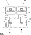
- FIG. 1 shows a highly schematic representation of a transmission topology which is particularly suitable for use as a basic structure of the present invention.
- the transmission arrangement shown comprises two electrical machines 10, 20, each with a housing-fixed stator 11, 21 and a rotor 12, 22 rotatably mounted in the stator 11, 21.
- the electrical machines 10, 20 are arranged coaxially and adjacent to one another.
- Each of the electrical machines 10, 20, in particular its rotor 12, 22, is connected to an associated planetary set 31, 32.
- Each planetary set 31, 32 comprises a sun 311, 321, a ring gear 312, 322 and a web 313, 323, on each of which a set of planetary gears 314, 324 is mounted.
- the planet gears 314, 324 mesh in the usual way with the assigned sun 311, 321 on the one hand and with the assigned ring gear 312, 322 on the other hand.
- the web 313 of the first planetary set 31 is firmly connected to the sun 321 of the second planetary set 32.
- the ring gears 312, 322, which are each connected to the rotor 12, 22 of the associated electrical machine 10, 20, can be temporarily coupled to the shaft connecting the first web 313 and the second sun 321.
- FIG 2 shows the actual switching mechanism of a gear arrangement according to the invention in its four possible positions in a highly schematic manner.
- the elements that can be coupled to one another are generally assumed to be a central wheel 40, a first coupling wheel 41 and a second coupling wheel 42 is described.
- the central wheel 40 can be a wheel which is fixed on the shaft which is shown in FIG Figure 1 the first planetary gear set 31, in particular its web 313, with the second planetary gear set 32, in particular its sun 321, connects.
- the coupling wheels 41 can be wheels that are fixed to the ring gears 312, 322 of the transmission arrangement of Figure 1 are connected.
- the central wheel 40 and the coupling wheels 41, 42 have external splines 401, 411, 421 of the same type.
- two shift sleeves 51, 52 are provided, which surround the central gear 40 and the coupling gears 41, 42 coaxially and each have an internal spline 511, 521 on their inner surfaces, which with the external spline 401, 411, 421 of the central wheel 40 and The coupling wheels 41, 42 correspond.
- a temporary coupling between the central wheel 40 and one of the coupling wheels 41, 42 can be created or separated temporarily by means of axial displacement of the shift sleeves 51, 52.
- each shift sleeve 51, 52 is mounted in an associated, coaxial sliding sleeve 71, 72 via an axial force-transmitting and at the same time rotationally decoupling bearing 61, 62, for example a deep groove ball bearing.
- Each sliding sleeve 71, 72 has a radially outwardly projecting guide pin 711, 721 which is formed in a guide groove 81, 82 assigned to it in the inner surface of a guide sleeve 80 arranged coaxially and fixed to the housing.
- the guide grooves 81, 82 represent curved grooves that extend essentially in the circumferential direction.
- the switching state therefore depends on the relative angular position of the sliding sleeves 61, 62 in relation to the guide sleeve 80 fixed to the housing.
- This angular position must be set precisely in order to carry out a switching process.
- a coaxial rotary sleeve 90 is provided radially between the sliding sleeves 61, 62 on the one hand and the guide sleeve 80 fixed to the housing on the other hand. This is rotatable, but axially fixed on the housing.
- the rotary sleeve 90 has an axially oriented slot 91 through which the guide pins 711, 721 pass radially.
- the guide pins 711, 721 are preferably supported in the axial slot in a form-fitting manner without play.
- An axial movement relative to the rotary sleeve 90 or to the guide sleeve 80 is not impaired because of the axial slot 91.
- a specific rotation of the rotary sleeve 90 is transmitted via the axial slot 91 to the guide pins 711, 721, which, following the curve shape of the guide grooves 81, 82, are forced into an axial movement unaffected by the axial slot 91.
- the rotary sleeve 90 For targeted rotational control of the rotary sleeve 90, it has, in its axial central area, a burr-like worm toothing 92, which radially penetrates a corresponding window 83 in the guide sleeve 80.
- the worm toothing 92 is therefore accessible from the radial outside for a correspondingly toothed spindle 93, which is rotatably mounted on the housing and is driven by an electric servomotor, not shown.
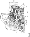
- FIG. 11 shows a partially sectioned, perspective illustration of a gear arrangement according to the invention with the topology of the arrangement from FIG Figure 1 and with a specific, constructive embodiment of the switching arrangement of Figure 2 .
- the references to the Figures 1 and 2 are evident from the reference numbers. With regard to the structure and mode of operation, refer to the above explanations Figure 1 and 2 referenced.
Landscapes
- Engineering & Computer Science (AREA)
- General Engineering & Computer Science (AREA)
- Mechanical Engineering (AREA)
- Physics & Mathematics (AREA)
- Electromagnetism (AREA)
- Structure Of Transmissions (AREA)
- Retarders (AREA)
Abstract
Description
- Die Erfindung bezieht sich auf eine schaltbare Getriebeanordnung, umfassend ein Gehäuse sowie ein außen steckverzahntes Zentralrad und ein einerseits des Zentralrades angeordnetes, gleichartig außen steckverzahntes, um dieselbe Rotationsachse drehbares, erstes Koppelrad, die mittels einer sie koaxial umgreifenden, korrespondierend innen steckverzahnten, axial verschieblichen ersten Schaltmuffe drehmomentübertragend miteinander koppelbar sind, wobei die erste Schaltmuffe drehentkoppelt und axial fest in einer koaxialen, ersten Schiebehülse gelagert ist, welche wenigstens einen nach radial außen gerichteten Führungszapfen aufweist, der in eine erste Führungsausnehmung einer Schaltwalze eingreift.
- Eine derartige Getriebeanordnung, die allgemein als Schaltmuffenanordnung bekannt ist, ist beispielsweise in der
DE 10 2004 058 475 A1 offenbart, ohne dass dort auf die konstruktiven Details eingegangen würde. - Eine in der Getriebetechnik häufig auftretende Aufgabenstellung besteht darin, zwei koaxiale, axial benachbart zueinander angeordnete Räder schaltbar miteinander zu koppeln, d.h. bedarfsweise drehmomentübertragend miteinander zu verbinden oder zu trennen. Es kann sich hierbei, wie bei der gattungsbildenden Druckschrift, um ein auf einer Welle fixiertes Festrad und ein auf derselben Welle gelagertes Losrad handeln. Denkbar sind jedoch auch schaltbare Kopplungen zwischen Elementen eines Planetensatzes. Aus später noch klarer werdenden Gründen sei eines der Räder hier als Zentral-, das andere als Koppelrad bezeichnet, wobei dies zunächst keinerlei konstruktive Festlegung impliziert. Die miteinander zu koppelnden Räder weisen gleichartige Außenverzahnung auf und werden koaxial von einer korrespondierend innenverzahnten Schaltmuffe umgriffen. Die Schaltmuffe ist axial verschieblich gelagert. In einer beide Räder überlappenden Axialposition der Schaltmuffe, in der ihre Innenverzahnung in die Außenverzahnungen beider Räder eingreift, sind Zentral- und Koppelrad drehmomentübertragend miteinander verbunden. In Axialpositionen hingegen, in denen die Schaltmuffe höchstens eines der beiden Räder axial überlappt, sind Zentral- und Koppelrad voneinander getrennt. Eine Problematik bei der Axialverschiebung der Schiebemuffe besteht darin, dass der Ausrückmechanismus typischerweise gehäusefest angeordnet ist, wohingegen die Schaltmuffe selbst aufgrund des Zahneingriffs mit dem bzw. den Rädern rotiert. Daher ist meist eine axial feste Drehentkopplung zu einer die Schaltmuffe koaxial umgreifenden Schiebehülse vorgesehen. Beispielsweise kann die Schaltmuffe mittels eines Rillenkugellagers in der Schiebehülse gelagert sein. Eine Axialverschiebung der Schiebehülse führt also zu einer gleichartigen Axialverschiebung der Schaltmuffe, wobei allerdings deren Rotation nicht auf die Schiebehülse übertragen wird. Zur Axialausrückung der Schiebehülse ist es bekannt, diese mit wenigstens einem nach radial außen gerichteten Führungszapfen zu versehen, der seinerseits in eine Führungsausnehmung, z.B. eine Führungsnut oder ein Führungsschlitz, einer Schaltwalze eingreift. Bei der Vorrichtung der gattungsbildenden Druckschrift ist die Schaltwalze als ein parallel zu den vorgenannten, koaxialen Elementen gelagerter Zylinder ausgebildet, in dessen Außenwand sich die gebogene Führungsausnehmung im Wesentlichen in Umfangsrichtung erstreckt. Sie bildet dabei eine lateral ausschwingende Führungskurve, in welche der Führungszapfen der Schiebehülse axial formschlüssig eingreift. Eine Rotation der Schaltwalze führt somit bei drehfest am Gehäuse gelagerter Schiebehülse zu einer der Kurvenform der Führungsausnehmung entsprechenden Axialverschiebung der Schiebehülse und damit der Schiebemuffe. Nachteilig bei dieser Ausgestaltung ist der radial große Bauraum, der durch die parallele Anordnung der Schaltwalze zu den übrigen Elementen der Schaltvorrichtung bedingt ist.
- Es ist die Aufgabe der vorliegenden Erfindung, eine gattungsgemäße Getriebeanordnung derart weiterzubilden, dass ein geringerer radialer Bauraum benötigt wird.
- Diese Aufgabe wird in Verbindung mit den Merkmalen des Oberbegriffs von Anspruch 1 dadurch gelöst, dass der Führungszapfen in tangential formschlüssiger Weise einen ersten Axialschlitz einer koaxialen, axial fest und rotierbar am Gehäuse gelagerten Drehhülse durchsetzt und die Schaltwalze als eine gehäusefeste, die Drehhülse axialbereichsweise, koaxial umgreifende Führungshülse ausgebildet ist, an deren Innenumfang sich die erste Führungsausnehmung in Umfangsrichtung erstreckt,
wobei die Drehhülse in einem von der Führungshülse radial nicht überdeckten Axialbereich eine sich in Umfangsrichtung erstreckende Schneckenverzahnung aufweist, die mit einer um ihre Spindelachse rotierbar am Gehäuse gelagerten Gewindespindel kämmt. - Bevorzugte Ausführungsformen der Erfindung sind Gegenstand der abhängigen Patentansprüche.
- Die Erfindung kombiniert drei konstruktive Aspekte zu einer besonders vorteilhaften, funktionalen Wirkung. Ein erster Aspekt betrifft die Gestaltung der Schaltwalze als hohlzylindrische Führungshülse, die die übrigen Elemente koaxial umgreift. Die Führungsausnehmung ist, anders als beim Stand der Technik, nicht in die Außen- sondern in die Innenwandung eingegraben. Dies führt neben dem offensichtlichen radialen Bauraumvorteil zu dem weiteren Vorteil, dass die axialkraftübertragende Verbindung zwischen der Schiebehülse und der Führungshülse nicht auf einen einzigen Führungszapfen beschränkt sein muss; vielmehr können mehrere über den Umfang verteilte Führungszapfen vorgesehen sein, die an unterschiedlichen Stellen in die (dann periodisch auszugestaltende) Führungsausnehmung eingreifen können. Dies führt zu einer Vergleichmäßigung der Krafteinleitung, die einem Verkanten entgegenwirkt.
- Ein zweiter Aspekt betrifft die gehäusefeste Anordnung der Führungshülse, was zunächst wiedersinnig erscheinen mag. Im Stand der Technik stellt die dortige Schaltführungswalze das eigentliche Betätigungsorgan dar, durch dessen Rotation die gewünschte Schaltung bewirkt wird. Eine Übernahme dieses Konzeptes auf die koaxiale Gestaltung der vorliegenden Erfindung hätte allerdings den Nachteil, dass das radial äußere Element der Schaltvorrichtung, nämlich die Führungshülse, relativ zu dem Getriebegehäuse drehbar gelagert sein müsste, was konstruktiv höchst aufwändig wäre. Die Erfindung sieht daher gemäß dem zweiten Aspekt eine gehäusefeste Anordnung dieses radial äußersten Elementes vor und kompensiert den dabei eingebüßten Bewegungsfreiheitsgrad durch ein zusätzliches Element. So ist erfindungsgemäß radial zwischen der Schiebehülse und der Führungshülse eine Drehhülse vorgesehen, die zwar axial fest aber zugleich rotierbar am Gehäuse gelagert ist. Diese Drehhülse weist einen Axialschlitz auf, durch welchen hindurch sich der Führungszapfen von seinem Fuß an der Schiebehülse zu seinem Kopf, der in die Führungsausnehmung in der Innenwand der Führungshülse eingreift, erstreckt. Die Breite des Axialschlitzes der Drehhülse ist derart auf den Durchmesser des Führungszapfens abgestimmt, dass letzterer ersteren in Umfangsrichtung formschlüssig durchgreift. Mit anderen Worten führt eine Rotation der Drehhülse spielfrei zu einer entsprechenden Rotation des Führungszapfens und mit ihm der Schiebehülse, wobei der Führungszapfen durch die Kurvenform der Führungsausnehmung zu einer Axialbewegung gezwungen wird, die von dem Axialschlitz in der Drehhülse zugelassen wird. Das eigentliche Betätigungsorgan der erfindungsgemäßen Schaltvorrichtung ist also besagte Drehhülse, durch deren gezielte Drehung der Führungszapfen in denjenigen Bereich der feststehenden Führungsausnehmung gedreht werden kann, dessen axiale Auslenkung der gewünschten Axialverschiebung der Schiebehülse und daher dem gewünschten Koppelzustand der Schaltmuffe entspricht.
- Zur konkreten (Dreh-)Betätigung der Drehhülse sieht die Erfindung gemäß ihrem dritten Aspekt vor, dass auf der Außenwand der Drehhülse eine sich in Umfangsrichtung erstreckende Schneckenverzahnung angeordnet ist. Diese erstreckt sich in einem Axialbereich der Drehhülse, der von der Führungshülse nicht umgriffen, d.h. von radial außen zugänglich ist. Beispielsweise kann ein entsprechendes Fenster in der Führungshülse vorgesehen sein. In besagte Schneckenverzahnung greift die Verzahnung einer Spindel ein, welche im Wesentlichen tangential zu den übrigen Elementen der Schaltungsanordnung und rotierbar am Gehäuse gelagert und vorzugsweise von einem elektrischen Stellmotor angetrieben ist.
- Die erläuterten drei Aspekte der vorliegenden Erfindung führen also zu einer schaltbaren Getriebeanordnung, die radial extrem kleinbauend ist und aufgrund des selbsthemmenden Schneckenantriebs in beide Drehrichtungen schnell und sehr präzise einstellbar ist.
- Eine Weiterbildung der Erfindung sieht die wahlweise Kopplung des Zentralrades mit einem oder beiden von zwei Koppelrädern vor, die auf unterschiedlichen axialen Seiten des Zentralrades angeordnet sind. Diese Anordnung macht auch die Terminologie eines "Zentralrades" zwischen zwei Koppelrädern verständlich.
- Speziell sieht die genannte Weiterbildung vor, dass andererseits des Zentralrades (d.h. auf der Seite, auf der das erste Koppelrad nicht angeordnet ist) ein gleichartig außen steckverzahntes, um dieselbe Rotationsachse drehbares, zweites Koppelrad angeordnet ist, welches mittels einer das zweite Koppelrad und das Zentralrad koaxial umgreifenden, korrespondierend innen steckverzahnten, axial verschieblichen, zweiten Schaltmuffe drehmomentübertragend mit dem Zentralrad koppelbar ist, wobei die zweite Schaltmuffe drehentkoppelt und axial fest in einer koaxialen, zweiten Schiebehülse gelagert ist, welche wenigstens einen nach radial außen gerichteten Führungszapfen aufweist, der in tangential formschlüssiger Weise einen zweiten Axialschlitz der Drehhülse durchsetzt und in eine sich in Umfangsrichtung erstreckende, zweite Führungsausnehmung der Führungshülse eingreift.
- Der oben im Kontext des ersten Koppelrades ausführlich erläuterte Schaltmechanismus wird also bei dieser Weiterbildung der Erfindung verdoppelt, wobei beide Teilvorrichtungen das Zentralrad, die Drehhülse und die Führungshülse gemeinsam nutzen. Die Drehhülse weist allerdings für jede der Teilvorrichtungen einen eigenen Axialschlitz auf, wobei beide Axialschlitze selbstverständlich auch als zwei Axialabschnitte eines durchgehenden Axialschlitzes ausgebildet sein können. Ebenso sind in der Führungshülse zwei Führungsausnehmungen, nämlich für jede Teilvorrichtung eine, vorgesehen. Durch die grundsätzlich unabhängige Wahl der Kurvenformen der beiden Führungsausnehmungen können beliebige, grundsätzlich voneinander unabhängige Schaltfolgen der Kopplungen der beiden Koppelräder mit dem Zentralrad realisiert werden.
- Bei einer Weiterbildung der erfindungsgemäßen schaltbaren Getriebeanordnung ist bevorzugt vorgesehen, dass die Führungshülse einen die erste Führungsausnehmung tragenden, ersten Axialbereich und einen die zweite Führungsausnehmung tragenden, zweiten Axialbereich aufweist, zwischen denen ein Spalt gebildet ist, in den hinein sich die Schneckenverzahnung der Drehhülse von radial innen her erstreckt. Mit anderen Worten ist die Einleitung der Betätigungskraft, d.h. die Einleitung des Drehmomentes auf die Drehhülse, an axial mittiger Position vorgesehen, was aus Symmetrie- und Lagerungsgründen vorteilhaft ist. Besagter Spalt kann in Umfangsrichtung begrenzt sein. Mit anderen Worten kann in der Führungshülse ein Fenster ausgebildet sein, durch welches die Schneckenverzahnung für die Betätigungsspindel zugänglich ist.
- Ein besonders bevorzugter Anwendungsbereich der erfindungsgemäßen Getriebeanordnung ist die Kopplung zweier Planetensätze. So ist bevorzugt vorgesehen, dass jedes Koppelrad das Hohlrad eines jeweils eine Sonne, ein Hohlrad und einen Steg mit Planetenrädern umfassenden Planetensatzes ist, wobei, besonders bevorzugt, das Zentralrad ein mit dem Steg eines der Planetensätze verbundenes Rad ist. Mit anderen Worten erlaubt eine solche Ausführungsform die Kopplung beider Planetensätze miteinander und alternativ oder zusätzlich die Verblockung eines der Planetensätze durch Kopplung zweier seiner Elemente miteinander.
- Alternativ oder zusätzlich kann vorgesehen sein, dass das Zentralrad ein mit der Sonne eines der Planetensätze drehfest verbundenes Rad ist. Insbesondere kann das Zentralrad mit einer Welle verbunden sein, die die Sonne des ersten Planetensatzes mit dem Steg des zweiten Planetensatzes verbindet.
- Weitere Einzelheiten und Vorteile der Erfindung ergeben sich aus der nachfolgenden, speziellen Beschreibung und den Zeichnungen.
- Es zeigen:
- Figur 1:
- eine schematische Darstellung einer bevorzugten Getriebeanordnung zur Anwendung der vorliegenden Erfindung,
- Figur 2:
- eine schematische Darstellung von vier Schaltstellungen des Schaltmechanismus einer erfindungsgemäßen Getriebeanordnung sowie
- Figur 3:
- eine teilweise geschnittene, perspektivische Ansicht einer Ausführungsform, welche den Schaltmechanismus von
Figur 2 mit der Getriebeanordnung vonFigur 1 kombiniert. - Gleiche Bezugszeichen in den Figuren weisen auf gleiche oder analoge Elemente hin.
-
Figur 1 zeigt in stark schematisierter Darstellung eine Getriebetopologie, die sich in besonderer Weise zum Einsatz als Basisstruktur der vorliegenden Erfindung eignet. Die dargestellte Getriebeanordnung umfasst zwei elektrische Maschinen 10, 20 mit jeweils einem gehäusefesten Stator 11, 21 und einem drehbar im Stator 11, 21 gelagerten Rotor 12, 22. Die elektrischen Maschinen 10, 20 sind koaxial zueinander und einander benachbart angeordnet. Jede der elektrischen Maschinen 10, 20, insbesondere ihr Rotor 12, 22 ist an einen zugeordneten Planetensatz 31, 32 angeschlossen. Jeder Planetensatz 31, 32 umfasst eine Sonne 311, 321, ein Hohlrad 312, 322 und einen Steg 313, 323, auf dem jeweils ein Satz Planetenräder 314, 324 gelagert ist. Die Planetenräder 314, 324 kämmen in üblicher Weise einerseits mit der zugeordneten Sonne 311, 321 und andererseits mit dem zugeordneten Hohlrad 312, 322. Bei der dargestellten Ausführungsform ist der Steg 313 des ersten Planetensatzes 31 fest mit der Sonne 321 des zweiten Planetensatzes 32 verbunden. Mittels einer inFigur 1 nicht im Detail dargestellten Schaltanordnung lassen sich die Hohlräder 312, 322, die jeweils mit dem Rotor 12, 22 der zugeordneten elektrischen Maschine 10, 20 verbunden sind, temporär mit der den ersten Steg 313 und die zweite Sonne 321 verbindenden Welle koppeln. Funktional umfasst die weiter unten, insbesondere im Kontext vonFigur 2 , noch näher zu beschreibende Schaltanordnung zwei Kupplungen, deren erste das Hohlrad 312 des ersten Planetensatzes 31 mit dessen Steg 313 koppelt und deren zweite das Hohlrad 322 des zweiten Planetensatzes 32 mit dessen Sonne 321 koppelt. Die beiden Kupplungen arbeiten grundsätzlich unabhängig voneinander, können jedoch, wie nachfolgend erläutert, in vorgegebenem Verhältnis zueinander geschaltet werden. Das Schließen jeder einzelnen Kupplung bedeutet eine Verblockung des zugeordneten Planetensatzes. -
Figur 2 zeigt stark schematisiert den eigentlichen Schaltmechanismus einer erfindungsgemäßen Getriebeanordnung in seinen vier möglichen Stellungen. Die miteinander koppelbaren Elemente seien hier allgemein als ein Zentralrad 40, ein erstes Koppelrad 41 und ein zweites Koppelrad 42 beschrieben. Bei dem Zentralrad 40 kann es sich um ein Rad handeln, welches auf derjenigen Welle fixiert ist, welche inFigur 1 den ersten Planetensatz 31, insbesondere dessen Steg 313, mit dem zweiten Planetensatz 32, insbesondere dessen Sonne 321, verbindet. Bei den Koppelrädern 41 kann es sich um Räder handeln, die fest mit den Hohlrädern 312, 322 der Getriebeanordnung vonFigur 1 verbunden sind. Das Zentralrad 40 und die Koppelräder 41, 42 weisen gleichartige Außen-Steckverzahnungen 401, 411, 421 auf. - Weiter sind zwei Schaltmuffen 51, 52 vorgesehen, die das Zentralrad 40 und die Koppelräder 41, 42 koaxial umgreifen und an ihren Innenflächen jeweils eine Innen-Steckverzahnung 511, 521 aufweisen, die mit den Außen-Steckverzahnungen 401, 411, 421 des Zentralrades 40 bzw. der Koppelräder 41, 42 korrespondieren. Wie in den unterschiedlichen Schaltstellungen der Teilfiguren a, b, c und d von
Figur 2 gezeigt, kann also mittels Axialverschiebung der Schaltmuffen 51, 52 eine temporäre Kopplung zwischen dem Zentralrad 40 und je einem der Koppelräder 41, 42 temporär geschaffen bzw. getrennt werden. - Hierzu ist jede Schaltmuffe 51, 52 über ein axialkraftübertragendes und zugleich drehentkoppelndes Lager 61, 62, beispielsweise ein Rillenkugellager, in einer zugeordneten, koaxialen Schiebehülse 71, 72 gelagert. Jede Schiebehülse 71, 72 weist einen nach radial außen ragenden Führungszapfen 711, 721 auf, der in eine ihm zugeordnete Führungsnut 81, 82 in der Innenfläche einer koaxial und gehäusefest angeordneten Führungshülse 80 ausgeformt ist. Die Führungsnuten 81, 82 stellen gebogene, sich jedoch im Wesentlichen in Umfangsrichtung erstreckende Nuten dar. Bei einer Rotation der Schiebehülsen 71, 72 um die gemeinsame Zentralachse und relativ zum Gehäuse gleiten die Führungszapfen 711, 721 in den zugeordneten Führungsnuten 81, 82 und werden, deren Kurvenform folgend, axial verschoben. Diese Axialverschiebung überträgt sich über die Lager 61, 62 auf die zugeordneten Schalmuffen 51, 52, sodass sich insgesamt der Schaltzustand der Anordnung verändert, wie in den Teilfiguren a, b, c und d von
Figur 2 gezeigt. - Der Schaltzustand hängt also von der relativen Winkellage der Schiebehülsen 61, 62 zur gehäusefesten Führungshülse 80 ab. Diese Winkellage muss zur Durchführung eines Schaltvorgangs präzise eingestellt werden. Hierzu ist radial zwischen den Schiebehülsen 61, 62 einerseits und der gehäusefesten Führungshülse 80 andererseits eine koaxiale Drehhülse 90 vorgesehen. Diese ist drehbar, jedoch axial fest am Gehäuse gelagert. Die Drehhülse 90 weist einen axial orientierten Schlitz 91 auf, der von den Führungszapfen 711, 721 radial durchsetzt wird. In tangentialer Richtung sind die Führungszapfen 711, 721 vorzugsweise spielfrei, formschlüssig in dem Axialschlitz gelagert. Eine axiale Relativbewegung zur Drehhülse 90 bzw. zur Führungshülse 80 wird aufgrund des Axialschlitzes 91 jedoch nicht beeinträchtigt. Eine gezielte Rotation der Drehhülse 90 wird also über den Axialschlitz 91 auf die Führungszapfen 711, 721 übertragen, die sodann, der Kurvenform der Führungsnuten 81, 82 folgend, in eine von dem Axialschlitz 91 unbeeinträchtigte Axialbewegung gezwungen werden.
- Zur gezielten Drehansteuerung der Drehhülse 90 weist diese in ihrem axialen Zentralbereich eine gratartig ausgestaltete Schneckenverzahnung 92 auf, die ein korrespondierendes Fenster 83 in der Führungshülse 80 radial durchsetzt. Die Schneckenverzahnung 92 wird daher von radial außen her für eine korrespondierend verzahnte Spindel 93 zugänglich, die rotierbar am Gehäuse gelagert und von einem nicht dargestellten elektrischen Stellmotor angetrieben ist.
-
Figur 3 zeigt eine teilweise geschnittene, perspektivische Darstellung einer erfindungsgemäßen Getriebeanordnung mit der Topologie der Anordnung vonFigur 1 und mit einer konkreten, konstruktiven Ausführungsform der Schaltanordnung vonFigur 2 . Die Bezüge zu denFiguren 1 und2 sind über die Bezugszeichen offensichtlich. Hinsichtlich der Struktur und Funktionsweise wird auf die obigen Erläuterungen zuFigur 1 und2 verwiesen. - Natürlich stellen die in der speziellen Beschreibung diskutierten und in den Figuren gezeigten Ausführungsformen nur illustrative Ausführungsbeispiele der vorliegenden Erfindung dar. Dem Fachmann ist im Lichte der hiesigen Offenbarung ein breites Spektrum an Variationsmöglichkeiten an die Hand gegeben. Insbesondere ist die erfindungswesentliche Schaltanordnung unabhängig von der Topologie auf beliebige Getriebestrukturen anwendbar.
-
- 10
- erste elektrische Maschine
- 11
- Stator von 10
- 12
- Rotor von 10
- 20
- zweite elektrische Maschine
- 21
- Stator von 20
- 22
- Rotor von 20
- 31
- erster Planetensatz
- 311
- Sonne von 31
- 312
- Hohlrad von 31
- 313
- Steg von 31
- 314
- Planetenrad von 31
- 32
- zweiter Planetensatz
- 321
- Sonne von 32
- 322
- Hohlrad von 32
- 323
- Steg von 32
- 324
- Planetenrad von 32
- 40
- Zentralrad
- 401
- Außen-Steckverzahnung von 40
- 41
- erstes Koppelrad
- 411
- Außen-Steckverzahnung von 41
- 42
- zweites Koppelrad
- 421
- Außen-Steckverzahnung von 42
- 51
- erste Schaltmuffe
- 511
- Innen-Steckverzahnung von 51
- 52
- zweite Schaltmuffe
- 521
- Innen-Steckverzahnung von 52
- 61
- erstes Lager
- 62
- zweites Lager
- 71
- erste Schiebehülse
- 711
- Führungszapfen von 71
- 72
- zweite Schiebehülse
- 721
- Führungszapfen von 72
- 80
- Führungshülse
- 81
- erste Führungsnut
- 82
- zweite Führungsnut
- 83
- Fenster
- 90
- Drehhülse
- 91
- Axialschlitz
- 92
- Schneckenverzahnung
- 93
- Gewindespindel
Claims (12)
- Schaltbare Getriebeanordnung, umfassend ein Gehäuse sowie ein außen steckverzahntes Zentralrad (40) und ein einerseits des Zentralrades (40) angeordnetes, gleichartig außen steckverzahntes, um dieselbe Rotationsachse drehbares, erstes Koppelrad (41), die mittels einer sie koaxial umgreifenden, korrespondierend innen steckverzahnten, axial verschieblichen ersten Schaltmuffe (51) drehmomentübertragend miteinander koppelbar sind, wobei die erste Schaltmuffe (51) drehentkoppelt und axial fest in einer koaxialen, ersten Schiebehülse (71) gelagert ist, welche wenigstens einen nach radial außen gerichteten Führungszapfen (711) aufweist, der in eine erste Führungsausnehmung (81) einer Schaltwalze eingreift,
dadurch gekennzeichnet,
dass der Führungszapfen (711) in tangential formschlüssiger Weise einen Axialschlitz (91) einer koaxialen, axial fest und rotierbar am Gehäuse gelagerten Drehhülse (90) durchsetzt und die Schaltwalze als eine gehäusefeste, die Drehhülse (90) axialbereichsweise, koaxial umgreifende Führungshülse (80) ausgebildet ist, an deren Innenumfang sich die erste Führungsausnehmung (81) in Umfangsrichtung erstreckt, wobei die Drehhülse (90) in einem von der Führungshülse (80) radial nicht überdeckten Axialbereich eine sich in Umfangsrichtung erstreckende Schneckenverzahnung (92) aufweist, die mit einer um ihre Spindelachse rotierbar am Gehäuse gelagerten Gewindespindel (93) kämmt. - Schaltbare Getriebeanordnung nach Anspruch 1,
dadurch gekennzeichnet,
dass die Gewindespindel (93) mit einem elektrischen Stellmotor gekoppelt ist, mittels dessen sie motorisch rotierbar ist. - Schaltbare Getriebeanordnung nach einem der vorangehenden Ansprüche,
dadurch gekennzeichnet,
dass andererseits des Zentralrades (40) ein gleichartig außen steckverzahntes, um dieselbe Rotationsachse drehbares, zweites Koppelrad (42) angeordnet ist, welches mittels einer das zweite Koppelrad (42) und das Zentralrad (40) koaxial umgreifenden, korrespondierend innen steckverzahnten, axial verschieblichen, zweiten Schaltmuffe (52) drehmomentübertragend mit dem Zentralrad (40) koppelbar ist, wobei die zweite Schaltmuffe (52) drehentkoppelt und axial fest in einer koaxialen, zweiten Schiebehülse (72) gelagert ist, welche wenigstens einen nach radial außen gerichteten Führungszapfen (721) aufweist, der in tangential formschlüssiger Weise einen Axialschlitz (91) der Drehhülse (90) durchsetzt und in eine sich in Umfangsrichtung erstreckende zweite Führungsausnehmung (82) der Führungshülse (80) eingreift. - Schaltbare Getriebeanordnung nach einem der vorangehenden Ansprüche,
dadurch gekennzeichnet,
dass jede Schaltmuffe (51, 52) mittels eines vollumfänglich erstreckten Rillenkugellagers (61, 62) von der ihr zugeordneten Schiebehülse (71, 72) drehentkoppelt ist. - Schaltbare Getriebeanordnung nach einem der vorangehenden Ansprüche,
dadurch gekennzeichnet,
dass jede Führungsausnehmung (81, 82) der Führungshülse als ein Führungsschlitz oder eine Führungsnut ausgebildet ist. - Schaltbare Getriebeanordnung nach Anspruch 3 oder einem der Ansprüche 4 bis 5, soweit rückbezogen auf Anspruch 3,
dadurch gekennzeichnet,
dass die Führungshülse (80) einen die erste Führungsausnehmung (81) tragenden, ersten Axialbereich und einen die zweite Führungsausnehmung (82) tragenden, zweiten Axialbereich aufweist, zwischen denen ein Spalt (83) gebildet ist, in den hinein sich die Schneckenverzahnung (92) der Drehhülse (90) von radial innen her erstreckt. - Schaltbare Getriebeanordnung nach Anspruch 6,
dadurch gekennzeichnet,
dass der Spalt (83) in Umfangsrichtung begrenzt ist. - Schaltbare Getriebeanordnung nach Anspruch 3 oder einem der Ansprüche 4 bis 7, soweit rückbezogen auf Anspruch 3,
dadurch gekennzeichnet,
dass den Schiebehülsen (71, 72) zugeordneten Axialschlitze der Drehhülse (90) als zwei Axialabschnitte eines durchgehenden Axialschlitzes (91) ausgebildet sind. - Schaltbare Getriebeanordnung nach einem der vorangehenden Ansprüche,
dadurch gekennzeichnet,
dass jedes Koppelrad (41, 42) das Hohlrad (312, 322) eines jeweils eine Sonne (311, 321), ein Hohlrad (312, 322) und einen Steg (313, 323) mit Planetenrädern (314, 324) umfassenden Planetensatzes (31, 32) ist. - Schaltbare Getriebeanordnung nach den Ansprüchen 3 und 9,
dadurch gekennzeichnet,
dass das Zentralrad (40) ein mit dem Steg (313) eines der Planetensätze (31) drehfest verbundenes Rad ist. - Schaltbare Getriebeanordnung nach Anspruch 3 und einem der Ansprüche 9 bis 10,
dadurch gekennzeichnet,
dass das Zentralrad (40) ein mit der Sonne (321) eines der Planetensätze (32) drehfest verbundenes Rad ist. - Schaltbare Getriebeanordnung nach einem der vorangehenden Ansprüche,
dadurch gekennzeichnet,
dass jede Schiebehülse (71, 72) über den Umfang verteilt eine Mehrzahl von Führungszapfen (711, 721) aufweist, die eine gleiche Anzahl korrespondierend angeordneter Axialschlitze (91) der Drehhülse (90) durchgreifen und in eine gleiche Anzahl korrespondierend angeordneter Führungsausnehmungen (81, 82) oder Abschnitte je einer Führungsausnehmung (81, 82) der Führungshülse (80) eingreifen.
Applications Claiming Priority (1)
| Application Number | Priority Date | Filing Date | Title |
|---|---|---|---|
| DE102019209180.6A DE102019209180A1 (de) | 2019-06-25 | 2019-06-25 | Schaltbare Getriebeanordnung |
Publications (2)
| Publication Number | Publication Date |
|---|---|
| EP3757416A1 true EP3757416A1 (de) | 2020-12-30 |
| EP3757416B1 EP3757416B1 (de) | 2023-01-18 |
Family
ID=70738319
Family Applications (1)
| Application Number | Title | Priority Date | Filing Date |
|---|---|---|---|
| EP20174870.4A Active EP3757416B1 (de) | 2019-06-25 | 2020-05-15 | Schaltbare getriebeanordnung |
Country Status (3)
| Country | Link |
|---|---|
| EP (1) | EP3757416B1 (de) |
| CN (1) | CN112128367B (de) |
| DE (1) | DE102019209180A1 (de) |
Cited By (1)
| Publication number | Priority date | Publication date | Assignee | Title |
|---|---|---|---|---|
| WO2025002693A1 (de) * | 2023-06-27 | 2025-01-02 | Bayerische Motoren Werke Aktiengesellschaft | Getriebe für ein kraftfahrzeug sowie kraftfahrzeug mit einem solchen getriebe |
Citations (3)
| Publication number | Priority date | Publication date | Assignee | Title |
|---|---|---|---|---|
| DE102004058475A1 (de) | 2004-11-23 | 2006-05-24 | Getrag Getriebe- Und Zahnradfabrik Hermann Hagenmeyer Gmbh & Cie Kg | Aktuatoranordnung mit Schaltwalzen für ein Doppelkupplungsgetriebe |
| CN101273212A (zh) * | 2005-09-26 | 2008-09-24 | 里卡多Uk有限公司 | 控制组件 |
| EP2679346A1 (de) * | 2011-02-22 | 2014-01-01 | Panasonic Corporation | Elektrowerkzeug |
Family Cites Families (4)
| Publication number | Priority date | Publication date | Assignee | Title |
|---|---|---|---|---|
| DE10361356B4 (de) * | 2003-12-17 | 2006-02-16 | Getrag Getriebe- Und Zahnradfabrik Hermann Hagenmeyer Gmbh & Cie Kg | Schaltwalze mit axial zur Schaltwalzenachse beweglicher Einlegenutflanke und Schaltverfahren |
| DE102005047107A1 (de) * | 2004-10-12 | 2006-04-13 | Luk Lamellen Und Kupplungsbau Beteiligungs Kg | Lastschaltgetriebe für Kraftahrzeuge, ein Kraftfahrzeug-Getriebe sowie einen Kraftfahrzeug-Antriebsstrang |
| DE102012004371A1 (de) * | 2012-03-02 | 2013-09-05 | Daimler Ag | Kraftfahrzeuggetriebebetätigungsvorrichtung |
| CN103062395B (zh) * | 2013-01-09 | 2015-08-05 | 浙江吉利汽车研究院有限公司杭州分公司 | 一种手动变速器换挡机构 |
-
2019
- 2019-06-25 DE DE102019209180.6A patent/DE102019209180A1/de not_active Withdrawn
-
2020
- 2020-05-15 EP EP20174870.4A patent/EP3757416B1/de active Active
- 2020-06-24 CN CN202010586289.5A patent/CN112128367B/zh active Active
Patent Citations (3)
| Publication number | Priority date | Publication date | Assignee | Title |
|---|---|---|---|---|
| DE102004058475A1 (de) | 2004-11-23 | 2006-05-24 | Getrag Getriebe- Und Zahnradfabrik Hermann Hagenmeyer Gmbh & Cie Kg | Aktuatoranordnung mit Schaltwalzen für ein Doppelkupplungsgetriebe |
| CN101273212A (zh) * | 2005-09-26 | 2008-09-24 | 里卡多Uk有限公司 | 控制组件 |
| EP2679346A1 (de) * | 2011-02-22 | 2014-01-01 | Panasonic Corporation | Elektrowerkzeug |
Cited By (1)
| Publication number | Priority date | Publication date | Assignee | Title |
|---|---|---|---|---|
| WO2025002693A1 (de) * | 2023-06-27 | 2025-01-02 | Bayerische Motoren Werke Aktiengesellschaft | Getriebe für ein kraftfahrzeug sowie kraftfahrzeug mit einem solchen getriebe |
Also Published As
| Publication number | Publication date |
|---|---|
| EP3757416B1 (de) | 2023-01-18 |
| CN112128367B (zh) | 2022-07-01 |
| CN112128367A (zh) | 2020-12-25 |
| DE102019209180A1 (de) | 2020-12-31 |
Similar Documents
| Publication | Publication Date | Title |
|---|---|---|
| EP3548772B1 (de) | Traktionsgetriebe und antriebseinheit für ein kraftfahrzeug | |
| DE3419462A1 (de) | Ausgleichsgetriebe | |
| DE102005061268B4 (de) | Reibungskupplung mit Aktuator und Tellerfeder | |
| DE102007046382B4 (de) | Rotations-Translationswandler, Aktuatoranordnung und Schaltkupplungsanordnung | |
| DE112015005422T5 (de) | Elektronisches Schloss | |
| AT518787B1 (de) | Zahnradanordnung | |
| EP2480372B1 (de) | Antriebsvorrichtung für werkzeugrevolver | |
| EP3622189B1 (de) | Doppelkupplungseinheit und elektroantrieb mit einer solchen doppelkupplungseinheit | |
| EP3368799B1 (de) | Schaltvorrichtung und antriebseinheit für ein kraftfahrzeug | |
| EP3757416B1 (de) | Schaltbare getriebeanordnung | |
| DE202005017525U1 (de) | Reibungskupplung | |
| WO2023274602A1 (de) | Getriebevorrichtung mit einer welle | |
| EP2616644A1 (de) | Vorrichtung zur phasenverschiebung des drehwinkels eines antriebsrades zu einem abtriebsrad | |
| DE10148503A1 (de) | Falzapparat mit umfangsverstellbarem Zylinder | |
| EP3908765B1 (de) | Aktuatoranordnung für eine kupplungsanordnung für einen antriebsstrang eines kraftfahrzeugs | |
| EP3682132A1 (de) | Freilaufkupplung mit reibungsinduzierter stellkraft | |
| WO2021004578A1 (de) | Parksperrenvorrichtung für eine elektrische antriebsachse und elektrische antriebsachse mit einer parksperrenvorrichtung | |
| EP3405692B1 (de) | Getriebewelle, bauteilpaarung und verfahren zum betrieb einer getriebewelle | |
| AT525577B1 (de) | Planetengetriebe | |
| EP1813466B1 (de) | Gelenkbeschlag | |
| EP3822513B1 (de) | Aktor mit kompakter interner drehmomentabstützung | |
| DE102004024965B3 (de) | Getriebe zur Einstellung eines Fahrzeugsitzes, insbesondere für einen Kraftfahrzeugsitz | |
| DE3906328A1 (de) | Drehfeststellungsvorrichtung fuer ein automatisches getriebe | |
| DE102014201251A1 (de) | Schaltvorrichtung | |
| DE10329809B4 (de) | Kupplung zur Drehmomentbegrenzung |
Legal Events
| Date | Code | Title | Description |
|---|---|---|---|
| PUAI | Public reference made under article 153(3) epc to a published international application that has entered the european phase |
Free format text: ORIGINAL CODE: 0009012 |
|
| STAA | Information on the status of an ep patent application or granted ep patent |
Free format text: STATUS: THE APPLICATION HAS BEEN PUBLISHED |
|
| AK | Designated contracting states |
Kind code of ref document: A1 Designated state(s): AL AT BE BG CH CY CZ DE DK EE ES FI FR GB GR HR HU IE IS IT LI LT LU LV MC MK MT NL NO PL PT RO RS SE SI SK SM TR |
|
| AX | Request for extension of the european patent |
Extension state: BA ME |
|
| STAA | Information on the status of an ep patent application or granted ep patent |
Free format text: STATUS: REQUEST FOR EXAMINATION WAS MADE |
|
| 17P | Request for examination filed |
Effective date: 20210630 |
|
| RBV | Designated contracting states (corrected) |
Designated state(s): AL AT BE BG CH CY CZ DE DK EE ES FI FR GB GR HR HU IE IS IT LI LT LU LV MC MK MT NL NO PL PT RO RS SE SI SK SM TR |
|
| GRAP | Despatch of communication of intention to grant a patent |
Free format text: ORIGINAL CODE: EPIDOSNIGR1 |
|
| STAA | Information on the status of an ep patent application or granted ep patent |
Free format text: STATUS: GRANT OF PATENT IS INTENDED |
|
| INTG | Intention to grant announced |
Effective date: 20221017 |
|
| GRAS | Grant fee paid |
Free format text: ORIGINAL CODE: EPIDOSNIGR3 |
|
| GRAA | (expected) grant |
Free format text: ORIGINAL CODE: 0009210 |
|
| STAA | Information on the status of an ep patent application or granted ep patent |
Free format text: STATUS: THE PATENT HAS BEEN GRANTED |
|
| AK | Designated contracting states |
Kind code of ref document: B1 Designated state(s): AL AT BE BG CH CY CZ DE DK EE ES FI FR GB GR HR HU IE IS IT LI LT LU LV MC MK MT NL NO PL PT RO RS SE SI SK SM TR |
|
| REG | Reference to a national code |
Ref country code: GB Ref legal event code: FG4D Free format text: NOT ENGLISH |
|
| REG | Reference to a national code |
Ref country code: DE Ref legal event code: R096 Ref document number: 502020002375 Country of ref document: DE |
|
| REG | Reference to a national code |
Ref country code: CH Ref legal event code: EP |
|
| REG | Reference to a national code |
Ref country code: AT Ref legal event code: REF Ref document number: 1544862 Country of ref document: AT Kind code of ref document: T Effective date: 20230215 Ref country code: IE Ref legal event code: FG4D Free format text: LANGUAGE OF EP DOCUMENT: GERMAN |
|
| REG | Reference to a national code |
Ref country code: LT Ref legal event code: MG9D |
|
| REG | Reference to a national code |
Ref country code: NL Ref legal event code: MP Effective date: 20230118 |
|
| P01 | Opt-out of the competence of the unified patent court (upc) registered |
Effective date: 20230523 |
|
| PG25 | Lapsed in a contracting state [announced via postgrant information from national office to epo] |
Ref country code: NL Free format text: LAPSE BECAUSE OF FAILURE TO SUBMIT A TRANSLATION OF THE DESCRIPTION OR TO PAY THE FEE WITHIN THE PRESCRIBED TIME-LIMIT Effective date: 20230118 |
|
| PG25 | Lapsed in a contracting state [announced via postgrant information from national office to epo] |
Ref country code: RS Free format text: LAPSE BECAUSE OF FAILURE TO SUBMIT A TRANSLATION OF THE DESCRIPTION OR TO PAY THE FEE WITHIN THE PRESCRIBED TIME-LIMIT Effective date: 20230118 Ref country code: PT Free format text: LAPSE BECAUSE OF FAILURE TO SUBMIT A TRANSLATION OF THE DESCRIPTION OR TO PAY THE FEE WITHIN THE PRESCRIBED TIME-LIMIT Effective date: 20230518 Ref country code: NO Free format text: LAPSE BECAUSE OF FAILURE TO SUBMIT A TRANSLATION OF THE DESCRIPTION OR TO PAY THE FEE WITHIN THE PRESCRIBED TIME-LIMIT Effective date: 20230418 Ref country code: LV Free format text: LAPSE BECAUSE OF FAILURE TO SUBMIT A TRANSLATION OF THE DESCRIPTION OR TO PAY THE FEE WITHIN THE PRESCRIBED TIME-LIMIT Effective date: 20230118 Ref country code: LT Free format text: LAPSE BECAUSE OF FAILURE TO SUBMIT A TRANSLATION OF THE DESCRIPTION OR TO PAY THE FEE WITHIN THE PRESCRIBED TIME-LIMIT Effective date: 20230118 Ref country code: HR Free format text: LAPSE BECAUSE OF FAILURE TO SUBMIT A TRANSLATION OF THE DESCRIPTION OR TO PAY THE FEE WITHIN THE PRESCRIBED TIME-LIMIT Effective date: 20230118 Ref country code: ES Free format text: LAPSE BECAUSE OF FAILURE TO SUBMIT A TRANSLATION OF THE DESCRIPTION OR TO PAY THE FEE WITHIN THE PRESCRIBED TIME-LIMIT Effective date: 20230118 |
|
| PG25 | Lapsed in a contracting state [announced via postgrant information from national office to epo] |
Ref country code: SE Free format text: LAPSE BECAUSE OF FAILURE TO SUBMIT A TRANSLATION OF THE DESCRIPTION OR TO PAY THE FEE WITHIN THE PRESCRIBED TIME-LIMIT Effective date: 20230118 Ref country code: PL Free format text: LAPSE BECAUSE OF FAILURE TO SUBMIT A TRANSLATION OF THE DESCRIPTION OR TO PAY THE FEE WITHIN THE PRESCRIBED TIME-LIMIT Effective date: 20230118 Ref country code: IS Free format text: LAPSE BECAUSE OF FAILURE TO SUBMIT A TRANSLATION OF THE DESCRIPTION OR TO PAY THE FEE WITHIN THE PRESCRIBED TIME-LIMIT Effective date: 20230518 Ref country code: GR Free format text: LAPSE BECAUSE OF FAILURE TO SUBMIT A TRANSLATION OF THE DESCRIPTION OR TO PAY THE FEE WITHIN THE PRESCRIBED TIME-LIMIT Effective date: 20230419 Ref country code: FI Free format text: LAPSE BECAUSE OF FAILURE TO SUBMIT A TRANSLATION OF THE DESCRIPTION OR TO PAY THE FEE WITHIN THE PRESCRIBED TIME-LIMIT Effective date: 20230118 |
|
| REG | Reference to a national code |
Ref country code: DE Ref legal event code: R097 Ref document number: 502020002375 Country of ref document: DE |
|
| PG25 | Lapsed in a contracting state [announced via postgrant information from national office to epo] |
Ref country code: SM Free format text: LAPSE BECAUSE OF FAILURE TO SUBMIT A TRANSLATION OF THE DESCRIPTION OR TO PAY THE FEE WITHIN THE PRESCRIBED TIME-LIMIT Effective date: 20230118 Ref country code: RO Free format text: LAPSE BECAUSE OF FAILURE TO SUBMIT A TRANSLATION OF THE DESCRIPTION OR TO PAY THE FEE WITHIN THE PRESCRIBED TIME-LIMIT Effective date: 20230118 Ref country code: EE Free format text: LAPSE BECAUSE OF FAILURE TO SUBMIT A TRANSLATION OF THE DESCRIPTION OR TO PAY THE FEE WITHIN THE PRESCRIBED TIME-LIMIT Effective date: 20230118 Ref country code: DK Free format text: LAPSE BECAUSE OF FAILURE TO SUBMIT A TRANSLATION OF THE DESCRIPTION OR TO PAY THE FEE WITHIN THE PRESCRIBED TIME-LIMIT Effective date: 20230118 Ref country code: CZ Free format text: LAPSE BECAUSE OF FAILURE TO SUBMIT A TRANSLATION OF THE DESCRIPTION OR TO PAY THE FEE WITHIN THE PRESCRIBED TIME-LIMIT Effective date: 20230118 |
|
| PLBE | No opposition filed within time limit |
Free format text: ORIGINAL CODE: 0009261 |
|
| STAA | Information on the status of an ep patent application or granted ep patent |
Free format text: STATUS: NO OPPOSITION FILED WITHIN TIME LIMIT |
|
| PG25 | Lapsed in a contracting state [announced via postgrant information from national office to epo] |
Ref country code: SK Free format text: LAPSE BECAUSE OF FAILURE TO SUBMIT A TRANSLATION OF THE DESCRIPTION OR TO PAY THE FEE WITHIN THE PRESCRIBED TIME-LIMIT Effective date: 20230118 |
|
| 26N | No opposition filed |
Effective date: 20231019 |
|
| REG | Reference to a national code |
Ref country code: CH Ref legal event code: PL |
|
| PG25 | Lapsed in a contracting state [announced via postgrant information from national office to epo] |
Ref country code: MC Free format text: LAPSE BECAUSE OF FAILURE TO SUBMIT A TRANSLATION OF THE DESCRIPTION OR TO PAY THE FEE WITHIN THE PRESCRIBED TIME-LIMIT Effective date: 20230118 |
|
| REG | Reference to a national code |
Ref country code: BE Ref legal event code: MM Effective date: 20230531 |
|
| PG25 | Lapsed in a contracting state [announced via postgrant information from national office to epo] |
Ref country code: SI Free format text: LAPSE BECAUSE OF FAILURE TO SUBMIT A TRANSLATION OF THE DESCRIPTION OR TO PAY THE FEE WITHIN THE PRESCRIBED TIME-LIMIT Effective date: 20230118 Ref country code: MC Free format text: LAPSE BECAUSE OF FAILURE TO SUBMIT A TRANSLATION OF THE DESCRIPTION OR TO PAY THE FEE WITHIN THE PRESCRIBED TIME-LIMIT Effective date: 20230118 Ref country code: LU Free format text: LAPSE BECAUSE OF NON-PAYMENT OF DUE FEES Effective date: 20230515 Ref country code: LI Free format text: LAPSE BECAUSE OF NON-PAYMENT OF DUE FEES Effective date: 20230531 Ref country code: CH Free format text: LAPSE BECAUSE OF NON-PAYMENT OF DUE FEES Effective date: 20230531 |
|
| REG | Reference to a national code |
Ref country code: IE Ref legal event code: MM4A |
|
| PG25 | Lapsed in a contracting state [announced via postgrant information from national office to epo] |
Ref country code: IE Free format text: LAPSE BECAUSE OF NON-PAYMENT OF DUE FEES Effective date: 20230515 |
|
| PG25 | Lapsed in a contracting state [announced via postgrant information from national office to epo] |
Ref country code: IE Free format text: LAPSE BECAUSE OF NON-PAYMENT OF DUE FEES Effective date: 20230515 |
|
| PG25 | Lapsed in a contracting state [announced via postgrant information from national office to epo] |
Ref country code: IT Free format text: LAPSE BECAUSE OF FAILURE TO SUBMIT A TRANSLATION OF THE DESCRIPTION OR TO PAY THE FEE WITHIN THE PRESCRIBED TIME-LIMIT Effective date: 20230118 Ref country code: FR Free format text: LAPSE BECAUSE OF NON-PAYMENT OF DUE FEES Effective date: 20230531 Ref country code: BE Free format text: LAPSE BECAUSE OF NON-PAYMENT OF DUE FEES Effective date: 20230531 |
|
| PG25 | Lapsed in a contracting state [announced via postgrant information from national office to epo] |
Ref country code: BG Free format text: LAPSE BECAUSE OF FAILURE TO SUBMIT A TRANSLATION OF THE DESCRIPTION OR TO PAY THE FEE WITHIN THE PRESCRIBED TIME-LIMIT Effective date: 20230118 |
|
| PG25 | Lapsed in a contracting state [announced via postgrant information from national office to epo] |
Ref country code: BG Free format text: LAPSE BECAUSE OF FAILURE TO SUBMIT A TRANSLATION OF THE DESCRIPTION OR TO PAY THE FEE WITHIN THE PRESCRIBED TIME-LIMIT Effective date: 20230118 |
|
| GBPC | Gb: european patent ceased through non-payment of renewal fee |
Effective date: 20240515 |
|
| PG25 | Lapsed in a contracting state [announced via postgrant information from national office to epo] |
Ref country code: GB Free format text: LAPSE BECAUSE OF NON-PAYMENT OF DUE FEES Effective date: 20240515 |
|
| PGFP | Annual fee paid to national office [announced via postgrant information from national office to epo] |
Ref country code: DE Payment date: 20250531 Year of fee payment: 6 |
|
| PGFP | Annual fee paid to national office [announced via postgrant information from national office to epo] |
Ref country code: AT Payment date: 20250721 Year of fee payment: 5 |
|
| PG25 | Lapsed in a contracting state [announced via postgrant information from national office to epo] |
Ref country code: CY Free format text: LAPSE BECAUSE OF FAILURE TO SUBMIT A TRANSLATION OF THE DESCRIPTION OR TO PAY THE FEE WITHIN THE PRESCRIBED TIME-LIMIT; INVALID AB INITIO Effective date: 20200515 |
|
| PG25 | Lapsed in a contracting state [announced via postgrant information from national office to epo] |
Ref country code: HU Free format text: LAPSE BECAUSE OF FAILURE TO SUBMIT A TRANSLATION OF THE DESCRIPTION OR TO PAY THE FEE WITHIN THE PRESCRIBED TIME-LIMIT; INVALID AB INITIO Effective date: 20200515 |
|
| PG25 | Lapsed in a contracting state [announced via postgrant information from national office to epo] |
Ref country code: TR Free format text: LAPSE BECAUSE OF FAILURE TO SUBMIT A TRANSLATION OF THE DESCRIPTION OR TO PAY THE FEE WITHIN THE PRESCRIBED TIME-LIMIT Effective date: 20230118 |