EP3757381A1 - Straddled vehicle - Google Patents
Straddled vehicle Download PDFInfo
- Publication number
- EP3757381A1 EP3757381A1 EP20182234.3A EP20182234A EP3757381A1 EP 3757381 A1 EP3757381 A1 EP 3757381A1 EP 20182234 A EP20182234 A EP 20182234A EP 3757381 A1 EP3757381 A1 EP 3757381A1
- Authority
- EP
- European Patent Office
- Prior art keywords
- duct
- air cleaner
- resonator
- cleaner case
- wall
- Prior art date
- Legal status (The legal status is an assumption and is not a legal conclusion. Google has not performed a legal analysis and makes no representation as to the accuracy of the status listed.)
- Granted
Links
Images


Classifications
-
- F—MECHANICAL ENGINEERING; LIGHTING; HEATING; WEAPONS; BLASTING
- F02—COMBUSTION ENGINES; HOT-GAS OR COMBUSTION-PRODUCT ENGINE PLANTS
- F02M—SUPPLYING COMBUSTION ENGINES IN GENERAL WITH COMBUSTIBLE MIXTURES OR CONSTITUENTS THEREOF
- F02M35/00—Combustion-air cleaners, air intakes, intake silencers, or induction systems specially adapted for, or arranged on, internal-combustion engines
- F02M35/16—Combustion-air cleaners, air intakes, intake silencers, or induction systems specially adapted for, or arranged on, internal-combustion engines characterised by use in vehicles
- F02M35/162—Motorcycles; All-terrain vehicles, e.g. quads, snowmobiles; Small vehicles, e.g. forklifts
-
- F—MECHANICAL ENGINEERING; LIGHTING; HEATING; WEAPONS; BLASTING
- F02—COMBUSTION ENGINES; HOT-GAS OR COMBUSTION-PRODUCT ENGINE PLANTS
- F02M—SUPPLYING COMBUSTION ENGINES IN GENERAL WITH COMBUSTIBLE MIXTURES OR CONSTITUENTS THEREOF
- F02M35/00—Combustion-air cleaners, air intakes, intake silencers, or induction systems specially adapted for, or arranged on, internal-combustion engines
- F02M35/02—Air cleaners
- F02M35/0201—Housings; Casings; Frame constructions; Lids; Manufacturing or assembling thereof
-
- F—MECHANICAL ENGINEERING; LIGHTING; HEATING; WEAPONS; BLASTING
- F02—COMBUSTION ENGINES; HOT-GAS OR COMBUSTION-PRODUCT ENGINE PLANTS
- F02M—SUPPLYING COMBUSTION ENGINES IN GENERAL WITH COMBUSTIBLE MIXTURES OR CONSTITUENTS THEREOF
- F02M35/00—Combustion-air cleaners, air intakes, intake silencers, or induction systems specially adapted for, or arranged on, internal-combustion engines
- F02M35/02—Air cleaners
- F02M35/024—Air cleaners using filters, e.g. moistened
- F02M35/02416—Fixing, mounting, supporting or arranging filter elements; Filter element cartridges
-
- F—MECHANICAL ENGINEERING; LIGHTING; HEATING; WEAPONS; BLASTING
- F02—COMBUSTION ENGINES; HOT-GAS OR COMBUSTION-PRODUCT ENGINE PLANTS
- F02M—SUPPLYING COMBUSTION ENGINES IN GENERAL WITH COMBUSTIBLE MIXTURES OR CONSTITUENTS THEREOF
- F02M35/00—Combustion-air cleaners, air intakes, intake silencers, or induction systems specially adapted for, or arranged on, internal-combustion engines
- F02M35/02—Air cleaners
- F02M35/024—Air cleaners using filters, e.g. moistened
- F02M35/02416—Fixing, mounting, supporting or arranging filter elements; Filter element cartridges
- F02M35/02433—Special alignment with respect to the air intake flow, e.g. angled or in longitudinal flow direction
-
- F—MECHANICAL ENGINEERING; LIGHTING; HEATING; WEAPONS; BLASTING
- F02—COMBUSTION ENGINES; HOT-GAS OR COMBUSTION-PRODUCT ENGINE PLANTS
- F02M—SUPPLYING COMBUSTION ENGINES IN GENERAL WITH COMBUSTIBLE MIXTURES OR CONSTITUENTS THEREOF
- F02M35/00—Combustion-air cleaners, air intakes, intake silencers, or induction systems specially adapted for, or arranged on, internal-combustion engines
- F02M35/12—Intake silencers ; Sound modulation, transmission or amplification
- F02M35/1255—Intake silencers ; Sound modulation, transmission or amplification using resonance
- F02M35/1266—Intake silencers ; Sound modulation, transmission or amplification using resonance comprising multiple chambers or compartments
-
- F—MECHANICAL ENGINEERING; LIGHTING; HEATING; WEAPONS; BLASTING
- F02—COMBUSTION ENGINES; HOT-GAS OR COMBUSTION-PRODUCT ENGINE PLANTS
- F02M—SUPPLYING COMBUSTION ENGINES IN GENERAL WITH COMBUSTIBLE MIXTURES OR CONSTITUENTS THEREOF
- F02M35/00—Combustion-air cleaners, air intakes, intake silencers, or induction systems specially adapted for, or arranged on, internal-combustion engines
- F02M35/14—Combined air cleaners and silencers
-
- B—PERFORMING OPERATIONS; TRANSPORTING
- B60—VEHICLES IN GENERAL
- B60Y—INDEXING SCHEME RELATING TO ASPECTS CROSS-CUTTING VEHICLE TECHNOLOGY
- B60Y2200/00—Type of vehicle
- B60Y2200/10—Road Vehicles
- B60Y2200/12—Motorcycles, Trikes; Quads; Scooters
-
- F—MECHANICAL ENGINEERING; LIGHTING; HEATING; WEAPONS; BLASTING
- F02—COMBUSTION ENGINES; HOT-GAS OR COMBUSTION-PRODUCT ENGINE PLANTS
- F02M—SUPPLYING COMBUSTION ENGINES IN GENERAL WITH COMBUSTIBLE MIXTURES OR CONSTITUENTS THEREOF
- F02M35/00—Combustion-air cleaners, air intakes, intake silencers, or induction systems specially adapted for, or arranged on, internal-combustion engines
- F02M35/02—Air cleaners
- F02M35/0201—Housings; Casings; Frame constructions; Lids; Manufacturing or assembling thereof
- F02M35/0204—Housings; Casings; Frame constructions; Lids; Manufacturing or assembling thereof for connecting or joining to other devices, e.g. pipes
-
- F—MECHANICAL ENGINEERING; LIGHTING; HEATING; WEAPONS; BLASTING
- F02—COMBUSTION ENGINES; HOT-GAS OR COMBUSTION-PRODUCT ENGINE PLANTS
- F02M—SUPPLYING COMBUSTION ENGINES IN GENERAL WITH COMBUSTIBLE MIXTURES OR CONSTITUENTS THEREOF
- F02M35/00—Combustion-air cleaners, air intakes, intake silencers, or induction systems specially adapted for, or arranged on, internal-combustion engines
- F02M35/02—Air cleaners
- F02M35/024—Air cleaners using filters, e.g. moistened
-
- F—MECHANICAL ENGINEERING; LIGHTING; HEATING; WEAPONS; BLASTING
- F02—COMBUSTION ENGINES; HOT-GAS OR COMBUSTION-PRODUCT ENGINE PLANTS
- F02M—SUPPLYING COMBUSTION ENGINES IN GENERAL WITH COMBUSTIBLE MIXTURES OR CONSTITUENTS THEREOF
- F02M35/00—Combustion-air cleaners, air intakes, intake silencers, or induction systems specially adapted for, or arranged on, internal-combustion engines
- F02M35/12—Intake silencers ; Sound modulation, transmission or amplification
- F02M35/1255—Intake silencers ; Sound modulation, transmission or amplification using resonance
Definitions
- the present invention relates to a straddled vehicle having a resonator provided in an air cleaner.
- Japanese Laid-Open Patent Publication No. 2015-63257 describes a motorcycle including an air cleaner case having a main chamber and left and right sub chambers, a first resonator arranged inside the main chamber, and a second resonator arranged inside the sub chambers.
- An opening for taking in the air is formed on the side of the air cleaner case, and an element is attached so as to cover the opening. The air that has been cleaned through the element flows into the main chamber and the sub chambers.
- the air cleaner is for cleaning the air by means of the element to supply a clean air to the internal combustion engine. If the volume of the air cleaner case on the downstream side relative to the element is small, it is not possible to quickly supply a sufficient amount of clean air to the internal combustion engine, thereby lowering the performance of the internal combustion engine.
- a first resonator is arranged inside the main chamber, and a second resonator is arranged inside the sub chambers.
- the volume of the main chamber and the volume of the sub chambers are reduced by the volumes of these resonators. That is, the volume of the air cleaner case on the downstream side relative to the element is reduced by the volumes of the resonators. Therefore, the performance of the internal combustion engine may lower.
- a straddled vehicle includes an air cleaner and a resonator.
- the air cleaner includes an air cleaner case, an element arranged inside the air cleaner case, and a duct that is attached to the element and at least a portion of which is arranged inside the air cleaner case, wherein the duct guides the air toward the element.
- the resonator has an outer wall arranged around the duct. The duct and the outer wall together define at least a portion of a resonance chamber of the resonator.
- the resonator is arranged by making use of the dead space around the duct.
- the duct itself is used as a member that forms a portion of the resonance chamber of the resonator. Therefore, it is possible to arrange the resonator without increasing the size of the air cleaner case.
- the resonator is arranged on the upstream side relative to the element. Thus, it is possible to ensure a sufficient volume of the air cleaner case on the downstream side relative to the element.
- a portion of the outer wall is arranged inside the air cleaner case, and another portion of the outer wall is arranged outside the air cleaner case.
- a portion of the resonator is arranged outside the air cleaner case. Since it is possible to reduce the volume of the resonator arranged inside the air cleaner case, it is possible to suppress an increase in the size of the air cleaner case.
- the element is attached to the air cleaner case.
- the outer wall is attached to the element and not attached to the air cleaner case.
- the element, the duct and the outer wall are attachable, as an integral part, to the air cleaner case.
- the attachment of the element and the resonator is made easy.
- the resonance chamber of the resonator includes a first resonance chamber, and a second resonance chamber partitioned from the first resonance chamber.
- the frequency of the noise that is reduced by the resonator depends on the volume of the resonance chamber.
- the volume of the resonance chamber is large, there may be a frequency domain where the noise-reducing effect is lowered, due to anti-resonance.
- the resonance chamber of the resonator is divided into at least two resonance chambers, it is possible to suppress the volume per resonance chamber. Therefore, it is possible to suppress anti-resonance.
- a volume of the first resonance chamber is different from a volume of the second resonance chamber.
- two resonance chambers of different frequency characteristics are used in combination with each other. This increases the range of frequency over which the noise is suppressed.
- the outer wall is inclined relative to a center line of the duct so as to move away from the center line of the duct while extending toward the element.
- the resonator is arranged in a compact arrangement.
- the resonator is able to be arranged close to the duct, and it is possible to effectively suppress noise.
- the air cleaner case has an opening into which the duct and the outer wall are inserted.
- a peripheral portion of the opening of the air cleaner case is inclined relative to the center line of the duct so as to move away from the center line of the duct while extending toward the element.
- the air cleaner case is shaped so as to extend along the outer wall of the resonator. Therefore, it is possible to reduce the size of a portion of the air cleaner case in the vicinity of the resonator.
- the duct includes an inlet opening and an outlet opening opposing the element.
- the resonator includes a bottom wall extending from the outlet opening of the duct radially outward of the outlet opening.
- the outer wall and the bottom wall are connected to each other.
- the duct, the outer wall and the bottom wall together define the resonance chamber of the resonator.
- the resonator is formed with a simple configuration.
- the bottom wall is spaced apart from the element and is arranged parallel to the element.
- the flow of the air having passed through the duct flares before the element. Therefore, it is possible to supply the air to a greater area of the element.
- the resonator includes a tubular portion having a first opening that is facing toward an outside of the air cleaner case, and a second opening that is facing toward the resonance chamber.
- the resonance frequency of the resonator is easily changed by changing the length or the passage cross-sectional area of the tubular portion. This makes it easy to adjust the resonance frequency of the resonator.
- the tubular portion is arranged outside the air cleaner case.
- a center line of the duct and a center line of the tubular portion are parallel to each other.
- the tubular portion is unlikely to interfere with the air passing through the duct. This smoothes the flow of the air through the duct.
- a length of the duct in a direction along the center line is shorter than an outer diameter of the duct.
- the air resistance of the duct is small. This smoothes the flow of the air through the duct.
- the duct is formed straight.
- the air resistance of the duct is small as compared with a case where the duct is bent or curved. This smoothes the flow of the air through the duct.
- the present invention it is possible to provide a straddled vehicle with which it is possible to ensure a sufficient volume of the air cleaner case on the downstream side relative to the element while suppressing an increase in size and reducing noise.
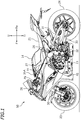
- FIG. 1 is a left side view of a motorcycle 50 according to the present embodiment.
- front, rear, left, right, up and down refer to these directions as seen from a virtual rider seated on a seat 21 while the motorcycle 50 is standing upright on a horizontal surface with no rider, no fuel and no load thereon, unless specified otherwise.
- front/forward refers not only to the direction that extends in the front direction along the vehicle center line, as the vehicle is seen from above, but also to directions that are inclined left/right from that direction by an angle that is less than or equal to 45 degrees.
- the term “rear/rearward” refers not only to the direction that extends rearward along the vehicle center line, as the vehicle is seen from above, but also to directions that are inclined left/right from that direction by an angle of 45 degrees of less.
- the term “left/leftward” refers not only to the direction that extends leftward vertical to the vehicle center line, as the vehicle is seen from above, but also to directions that are inclined frontward/rearward from that direction by an angle of 45 degrees of less.
- the term “right/rightward” refers not only to the direction that extends rightward vertical to the vehicle center line, as the vehicle is seen from above, but also to directions that are inclined frontward/rearward from that direction by an angle of 45 degrees of less.
- up/upward refers not only to the vertically upward direction, as the vehicle is seen from sideways, but also to directions that are inclined frontward/rearward from that direction by an angle of 45 degrees of less.
- down/downward refers not only to the vertically downward direction, as the vehicle is seen from sideways, but also to directions that are inclined frontward/rearward from that direction by an angle of 45 degrees of less.
- the motorcycle 50 includes a vehicle frame 22, a front wheel 23, a rear wheel 24, an internal combustion engine (hereinafter "engine”) 15, an air cleaner 35 covered by an external cover 35A (see FIG. 2 ), a fuel tank 14, and the seat 21. At least a portion of the air cleaner 35 is arranged forward of the fuel tank 14. The seat 21 is arranged rearward of the fuel tank 14.
- engine internal combustion engine
- the vehicle frame 22 includes a head pipe 26, left and right side frames 27 extending rearward and outward in the vehicle width direction from the head pipe 26, and left and right down frames 28 extending downward from the rear end of the left and right side frames 27, respectively.
- a steering shaft (not shown), to which a handle 29 is secured, is supported on the head pipe 26 so that the steering shaft can pivot left and right.
- the steering shaft is secured to a front fork 30.
- the front wheel 23 is supported on the front fork 30.
- the rear wheel 24 is supported on a rear end portion of a rear arm 31.
- the front end portion of the rear arm 31 is supported by a pivot shaft 32 so that the rear arm 31 can pivot up and down relative to the down frame 28.
- the front wheel 23 is a driven wheel.
- the rear wheel 24 is a driving wheel that is driven by the engine 15.
- the engine 15 and the rear wheel 24 are linked by a chain 33.
- the chain 33 is an example of a power transmission member. Note however that the power transmission member that transmits the power of the engine 15 to the rear wheel 24 is not limited to the chain 33, but it may be a transmission belt, a drive shaft, etc.
- FIG. 2 is a right side view of a portion of the vehicle frame 22, the engine 15, the air cleaner 35 and the fuel tank 14.
- FIG. 3 is a cross-sectional view of the engine 15 and the air cleaner 35 as seen from the right side.
- the engine 15 is supported on the vehicle frame 22.
- the engine 15 includes a crankshaft 1, a crankcase 2, a cylinder body 3, a cylinder head 5, and a cylinder head cover 36.
- the engine 15 includes an intake valve 7, an exhaust valve 37, an intake cam 8, an exhaust cam 38, an intake pipe 10, an exhaust pipe 40 (see FIG. 1 ), a fuel injector 12, a fuel injector 12B, a throttle valve 11, and a motor 13 for actuating the throttle valve 11.
- the crankshaft 1 extends in the vehicle width direction.
- the crankshaft 1 is arranged inside the crankcase 2.
- the crankcase 2 rotatably supports the crankshaft 1.
- the cylinder body 3 extends forward and upward from the crankcase 2.
- a cylinder 4 is formed inside the cylinder body 3.
- a piston 18 is arranged inside the cylinder 4.
- a connecting rod 20 is linked to the piston 18 and the crankshaft 1.
- the piston 18 is linked to the crankshaft 1 via the connecting rod 20.
- reference sign 67 denotes a balancer gear
- reference sign 68 denotes a clutch.
- the cylinder head 5 is connected to the cylinder body 3.
- the cylinder head 5 extends forward and upward from the cylinder body 3.
- the cylinder head cover 36 is connected to the cylinder head 5.
- the cylinder head cover 36 extends forward and upward from the cylinder head 5.
- An intake opening 6 and an exhaust opening 39 are formed inside the cylinder head 5 with their openings facing toward the inside of the cylinder 4.
- An intake port 9 connected to the intake opening 6 and an exhaust port 41 connected to the exhaust opening 39 are formed inside the cylinder head 5.
- the intake valve 7 and the exhaust valve 37 are supported on the cylinder head 5.
- the intake valve 7 covers the intake opening 6 so that it can open/close the intake opening 6, and the exhaust valve 37 covers the exhaust opening 39 so that it can open/close the exhaust opening 39.
- the intake cam 8 and the exhaust cam 38 are rotatably supported on the cylinder head 5.
- the intake cam 8 rotates to thereby open/close the intake valve 7.
- the exhaust cam 38 rotates to thereby open/close the exhaust valve 37.
- the intake pipe 10 is connected to the cylinder head 5 and is connected to the intake port 9.
- the intake pipe 10 is configured to guide the air to the intake port 9.
- the intake pipe 10 extends upward from the cylinder head 5. Specifically, the intake pipe 10 extends upward and rearward from the cylinder head 5.
- the intake pipe 10 includes a first intake pipe 10A and a second intake pipe 10B.
- the first intake pipe 10A is arranged upward of the second intake pipe 10B.
- the first intake pipe 10A is arranged on the upstream side relative to the second intake pipe 10B.
- the first intake pipe 10A is attachable to and detachable from the second intake pipe 10B.
- the motorcycle 50 includes an actuator 10K that actuates the first intake pipe 10A.
- the actuator 10K moves the first intake pipe 10A downward, the first intake pipe 10A is connected to the second intake pipe 10B. Then, the air is sucked in through an inlet 10Ai of the first intake pipe 10A, passes through the first intake pipe 10A and the second intake pipe 10B, and then flows into the intake port 9.
- the actuator 10K moves the first intake pipe 10A upward, the first intake pipe 10A moves apart from the second intake pipe 10B. Then, the air is sucked in through an inlet 10Bi of the second intake pipe 10B, passes through the second intake pipe 10B, and is then sucked into the intake port 9.
- the length of the intake pipe 10 becomes the total length of the length of the first intake pipe 10A and the length of the second intake pipe 10B.
- the length of the intake pipe 10 becomes equal to the length of the second intake pipe 10B.
- the length of the intake pipe 10 is varied. Note however that the length of the intake pipe 10 does not always need to be variable.
- the first intake pipe 10A and the second intake pipe 10B may be always connected to each other.
- the first intake pipe 10A and the second intake pipe 10B may be integral with each other.
- the first intake pipe 10A may be omitted.
- the throttle valve 11 is arranged inside the intake pipe 10. Specifically, the throttle valve 11 is arranged inside the second intake pipe 10B. The throttle valve 11 is actuated by the motor 13. The motor 13 is linked to the throttle valve 11 so that power is transmitted therebetween. At least a portion of the motor 13 is arranged rearward of the intake pipe 10. Herein, the entirety of the motor 13 is arranged rearward of the intake pipe 10.
- the fuel injector 12 is attached to the intake pipe 10. Specifically, the fuel injector 12 is attached to the second intake pipe 10B. The fuel injector 12 is attached so as to extend upward from the intake pipe 10. At least a portion of the fuel injector 12 is arranged forward of the intake pipe 10.
- the fuel injector 12B is attached to an air cleaner case 17.
- the fuel injector 12B is arranged upward of the intake pipe 10.
- the fuel injector 12B is arranged upward of the first intake pipe 10A.
- the air cleaner 35 is arranged in the vicinity of the engine 15.
- a portion of the air cleaner 35 is at the same location, for the up-down direction, as a portion of the engine 15.
- a portion of the air cleaner 35 is at the same position, for the front-rear direction, as a portion of the engine 15.
- a lower end 35d of the air cleaner 35 is located downward relative to an upper end 15u of the engine 15.
- a front end 35f of the air cleaner 35 is located forward relative to a rear end 15r of the engine 15, and a rear end 35r of the air cleaner 35 is located rearward relative to a front end 15f of the engine 15.
- FIG. 4 is a cross-sectional view of the air cleaner 35 as seen from the left side. As shown in FIG. 4 , the air cleaner 35 includes the air cleaner case 17, the element 45 and a duct 47.
- the air cleaner case 17 has an opening 17b and a connection port 17a to which the intake pipe 10 is connected (see FIG. 3 ).
- the air cleaner case 17 has an attachment port 17c to which the fuel injector 12B is attached.
- the air cleaner case 17 includes an upper case 17A and a lower case 17B.
- the air cleaner case 17 is formed by assembling the upper case 17A and the lower case 17B together.
- the attachment port 17c is formed in the upper case 17A, and the opening 17b and the connection port 17a are formed in the lower case 17B. Note however that the present invention is in no way limited to this.
- the opening 17b may be formed in the upper case 17A.
- the air cleaner case 17 may be composed of three or more components.
- the element 45 is arranged inside the air cleaner case 17.
- the inside of the air cleaner case 17 is partitioned by the element 45 into a pre-cleaning chamber 51 and a post-cleaning chamber 52.
- the pre-cleaning chamber 51 is located on the upstream side relative to the element 45
- the post-cleaning chamber 52 is located on the downstream side relative to the element 45. Note that the upstream side refers to the side from which the air flows, and the downstream side refers to the side to which the air flows.
- the air before being cleaned by the element 45 flows into the pre-cleaning chamber 51.
- the air after being cleaned by the element 45 flows into the post-cleaning chamber 52.
- a clean air is stored in the post-cleaning chamber 52.
- the duct 47 is configured to guide the air toward the element 45.
- the duct 47 is attached to the element 45 with an outer wall 49 to be described below interposed therebetween.
- At least a portion of the duct 47 is arranged inside the air cleaner case 17.
- a portion of the duct 47 is arranged inside the air cleaner case 17, and the other portion thereof is arranged outside the air cleaner case 17.
- the duct 47 includes an inlet opening 47i, and an outlet opening 47o opposing the element 45. While the duct 47 may be bent or curved, the duct 47 is formed straight in the present embodiment.
- the cross section of the duct 47 may have a circular shape, or any other shape such as an elliptical shape, a square shape, a rectangular shape or a pentagonal shape.
- the duct 47 is formed in an oblong circular shape of which the dimension in the left-right direction is greater than the dimension in the front-rear direction.
- the length of the duct 47 in the direction along the center line 47c is shorter than the outer diameter of the duct 47. Note that where the cross section of the duct 47 does not have a circular shape, the outer diameter of the duct 47 refers to the hydraulic diameter.
- a bottom wall 54 extending radially outward from the outlet opening 47o is attached to the duct 47. While the bottom wall 54 may be inclined relative to the duct 47, it is herein arranged perpendicular to the duct 47. The bottom wall 54 is spaced apart from the element 45 and is arranged parallel to the element 45.
- a resonator 48 is formed using the duct 47.
- the resonator 48 includes the outer wall 49 arranged around the duct 47, and the duct 47 and the outer wall 49 together define at least a portion of a resonance chamber 60 of the resonator 48.
- the duct 47, the outer wall 49 and the bottom wall 54 together define the resonance chamber 60 of the resonator 48.
- a portion of the outer wall 49 is arranged inside the air cleaner case 17, and the other portion thereof is arranged outside the air cleaner case 17.
- the outer wall 49 is integral with the duct 47.
- the outer wall 49 and the duct 47 are formed of a single component.
- the outer wall 49 is attached to the element 45 and not attached to the air cleaner case 17. Note that not attached to the air cleaner case 17 herein means that it is not attached directly to the air cleaner case 17.
- the outer wall 49 is attached indirectly to the air cleaner case 17 with the element 45 interposed therebetween.
- the outer wall 49 is formed non-parallel to the duct 47.
- the outer wall 49 is inclined relative to the center line 47c of the duct 47 so as to move away from the center line 47c of the duct 47 while extending toward the element 45.
- the width of the resonator 48 decreases while extending away from the element 45.
- the duct 47 and the outer wall 49 are inserted into the opening 17b of the air cleaner case 17.
- a peripheral portion 17s of the opening 17b of the air cleaner case 17 is shaped so as to extend along the outer wall 49.
- the peripheral portion 17s of the opening 17b of the air cleaner case 17 is inclined relative to the center line 47c of the duct 47 so as to move away from the center line 47c of the duct 47 while extending toward the element 45.
- the inside of the resonator 48 is herein divided by partition walls 57 and 58 into a first resonance chamber 61 and a second resonance chamber 62, as shown in FIG. 5 .
- the second resonance chamber 62 is arranged rightward of the first resonance chamber 61.
- the resonator 48 includes two resonance chambers 61 and 62.
- the first resonance chamber 61 is formed in a C-letter shape
- the second resonance chamber 62 is formed in an inverted C-letter shape. While the volume of the first resonance chamber 61 and the volume of the second resonance chamber 62 may be equal to each other, they are herein different from each other.
- the resonator 48 includes a first tubular portion 71 connected to the first resonance chamber 61, and a second tubular portion 72 connected to the second resonance chamber 62.
- the first tubular portion 71 and the second tubular portion 72 are arranged outside the air cleaner case 17. While the first tubular portion 71 and the second tubular portion 72 may be bent or curved, they are herein formed straight.
- the center line 70c of the first tubular portion 71 (see FIG. 4 ) is parallel to the center line 47c of the duct 47.
- the center line of the second tubular portion 72 is also parallel to the center line 47c of the duct 47.
- the first tubular portion 71 includes a first opening 71a that is facing toward the outside of the air cleaner case 17, and a second opening 71b that is facing toward the first resonance chamber 61.
- the second tubular portion 72 includes a first opening 72a that is facing toward the outside of the air cleaner case 17, and a second opening 72b that is facing toward the second resonance chamber 62.
- the first resonance chamber 61 communicates with the outside through the first tubular portion 71
- the second resonance chamber 62 communicates with the outside through the second tubular portion 72.
- the first openings 71a and 72a are facing forward and downward. Note however that there is no limitation on the configuration.
- the motorcycle 50 is configured as described above. Next, various effects of the motorcycle 50 according to the present embodiment will be described.
- the motorcycle 50 according to the present embodiment includes the resonator 48, it is possible to reduce the noise from the engine 15 by means of the resonator 48.
- the resonator 48 is arranged by making use of the dead space around the duct 47 of the air cleaner 35. Moreover, the duct 47 itself is used as a member that forms a portion of the resonator 48. Therefore, it is possible to arrange the resonator 48 without increasing the size of the air cleaner case 17. Since there is no need to increase the size of the air cleaner case 17, it is possible to suppress an increase in the size of the motorcycle 50.
- the resonator 48 is arranged on the upstream side relative to the element 45.
- a portion of the outer wall 49 that forms a portion of the resonator 48 is arranged outside the air cleaner case 17. Since it is possible to reduce the volume of the resonator 48 arranged inside the air cleaner case 17, it is possible to suppress an increase in the size of the air cleaner case 17.
- the resonator 48 is composed of the duct 47, the outer wall 49 and the bottom wall 54.
- the resonator 48 is formed with a simple configuration.
- the duct 47 is integral with the outer wall 49, and the bottom wall 54 is attached to the outer wall 49 and the duct 47. While the outer wall 49 is attached to the element 45, it is not attached directly to the air cleaner case 17. According to the present embodiment, the element 45, the duct 47 and the outer wall 49 are attached, as an integral part, to the air cleaner case 17.
- the resonator 48 is assembled to the element 45, and is not attached directly to the air cleaner case 17. According to the present embodiment, there is no need to separately attach the element 45 and the resonator 48 to the air cleaner case 17. The resonator 48 is installed simply by attaching the element 45 to the air cleaner case 17. Thus, the attachment of the element 45 and the resonator 48 is made easy.
- the resonance chamber 60 of the resonator 48 includes the first resonance chamber 61, and the second resonance chamber 62 partitioned from the first resonance chamber 61.
- the frequency of the noise that is reduced by the resonator 48 depends on the volume of the resonance chamber of the resonator 48.
- the frequency of the noise of the engine 15 is spread over a wide range, it can be addressed by increasing the volume without dividing the resonance chamber 60 in two.
- the volume is increased, however, there may be a frequency domain where the noise-reducing effect is lowered, due to anti-resonance.
- since the resonance chamber 60 of the resonator 48 is divided into the first resonance chamber 61 and the second resonance chamber 62, it is possible to suppress anti-resonance.
- volume of the first resonance chamber 61 and the volume of the second resonance chamber 62 may be equal to each other, they may be different from each other in the present embodiment. Then, it is possible to provide two resonators of different frequency characteristics. This increases the range of frequency over which the noise is suppressed.
- the outer wall 49 of the resonator 48 is inclined relative to the center line 47c of the duct 47 so as to move away from the center line 47c of the duct 47 while extending toward the element 45.
- the resonator 48 is arranged in a compact arrangement. Moreover, the resonator 48 is arranged close to the duct 47, and it is possible to effectively suppress noise.
- the peripheral portion 17s of the opening 17b of the air cleaner case 17 is shaped so as to extend along the outer wall 49 of the resonator 48. Therefore, it is possible to reduce the size of a portion of the air cleaner case 17 in the vicinity of the resonator 48.
- the bottom wall 54 of the resonator 48 is spaced apart from the element 45 and is arranged parallel to the element 45.
- the flow of the air having passed through the duct 47 flares before the element 45. Therefore, it is possible to supply the air to a greater area of the element 45. Thus, it is possible to ensure a sufficient cleaning capacity of the air cleaner 35.
- the resonator 48 includes the first tubular portion 71 and the second tubular portion 72.
- the resonance frequency of the resonator 48 is easily changed by changing the length or the passage cross-sectional area of the first tubular portion 71 and the second tubular portion 72. Therefore, it is possible to adjust the resonance frequency of the resonator 48. It is possible to effectively suppress noise by matching the resonance frequency of the resonator 48 with the frequency of the noise of the engine 15.
- the first tubular portion 71 and the second tubular portion 72 are arranged outside the air cleaner case 17. It is possible to ensure a larger volume of the air cleaner case 17 as compared with a case where the first tubular portion 71 and the second tubular portion 72 are arranged inside the air cleaner case 17.
- the center line 70c of the first tubular portion 71 and the second tubular portion 72 is parallel to the center line 47c of the duct 47.
- the first tubular portion 71 and the second tubular portion 72 are unlikely to interfere with the air passing through the duct 47. This smoothes the flow of the air through the duct 47.
- the length of the duct 47 in the direction along the center line 47c is shorter than the outer diameter of the duct 47. Since the length of the duct 47 is relatively short, the air resistance of the duct 47 is small. This smoothes the flow of the air through the duct 47.
- the duct 47 is formed straight.
- the air resistance of the duct 47 is small as compared with a case where the duct 47 is bent or curved. This smoothes the flow of the air through the duct 47.
- a resonator 80 may be provided in the post-cleaning chamber 52 as indicated by a phantom line in FIG. 4 .
- a resonance chamber 83 may be defined by a portion 17h of the air cleaner case 17 and a case 81, and the resonator 80 may be formed by connecting a tubular portion 82 to the case 81. Then, it is possible to further reduce the noise of the engine 15.
- the air cleaner 35 Since there is ensured a sufficient volume of the post-cleaning chamber 52 of the air cleaner 35, the air cleaner 35 will not be too large even if an additional resonator 80 is arranged inside the post-cleaning chamber 52. If the volume of the first resonance chamber 61, the volume of the second resonance chamber 62 and the volume of the resonance chamber 83 are different from each other, it is possible to reduce noise over an even wider range of frequency. With a straddled vehicle like the motorcycle 50, as compared with an automobile, there tends to be more variations of the rotation speed of the engine 15. With the provision of three resonance chambers 61, 62 and 83 of different volumes, it is possible to reduce noise for a wide range of engine rotation speed.
- the resonator 48 While a portion of the resonator 48 is arranged outside the air cleaner case 17 in the embodiment described above, there is no particular limitation thereto. The entirety of the resonator 48 may be arranged inside the air cleaner case 17.
- resonator 48 is attached to the element 45 and not attached directly to the air cleaner case 17 in the embodiment described above, there is no particular limitation thereto.
- the resonator 48 may be attached directly to the air cleaner case 17.
- outer wall 49 of the resonator 48 is inclined relative to the center line 47c of the duct 47 in the embodiment described above, there is no particular limitation thereto.
- the outer wall 49 may be parallel to the center line 47c of the duct 47.
- bottom wall 54 of the resonator 48 is perpendicular to the center line 47c of the duct 47 and is arranged parallel to the element 45 in the embodiment described above, there is no particular limitation thereto.
- the bottom wall 54 may be inclined relative to the center line 47c of the duct 47 so as to extend radially outward of the duct 47 while extending toward the element 45. Then, it is possible to more smoothly supply the air from the duct 47 toward the element 45.
- the engine 15 may be a multi-cylinder internal combustion engine including a plurality of cylinders 4 or may be a single-cylinder internal combustion engine including only one cylinder 4.
- the internal combustion engine may be a water-cooled internal combustion engine or may be an air-cooled internal combustion engine.
- a straddled vehicle refers to a vehicle that is straddled by a passenger. While a motorcycle is an example of a straddled vehicle, a straddled vehicle is not limited to a motorcycle.
- a straddled vehicle may include an auto tricycle, an ATV (All Terrain Vehicle), and the like, as well as a motorcycle.
Landscapes
- Engineering & Computer Science (AREA)
- Chemical & Material Sciences (AREA)
- Combustion & Propulsion (AREA)
- Mechanical Engineering (AREA)
- General Engineering & Computer Science (AREA)
- Manufacturing & Machinery (AREA)
- Automatic Cycles, And Cycles In General (AREA)
Abstract
Description
- The present invention relates to a straddled vehicle having a resonator provided in an air cleaner.
- Conventional straddled vehicles having an air cleaner and a resonator provided in the air cleaner are known in the art. For example, Japanese Laid-Open Patent Publication No.
2015-63257 - The air cleaner is for cleaning the air by means of the element to supply a clean air to the internal combustion engine. If the volume of the air cleaner case on the downstream side relative to the element is small, it is not possible to quickly supply a sufficient amount of clean air to the internal combustion engine, thereby lowering the performance of the internal combustion engine.
- With the straddled vehicle disclosed in Japanese Laid-Open Patent Publication No.
2015-63257 - It is an object of the present invention, which has been made in order to solve the problem, to provide a straddled vehicle with which it is possible to ensure a sufficient volume of the air cleaner case on the downstream side relative to the element while suppressing an increase in size and reducing noise.
- A straddled vehicle according to the present invention includes an air cleaner and a resonator. The air cleaner includes an air cleaner case, an element arranged inside the air cleaner case, and a duct that is attached to the element and at least a portion of which is arranged inside the air cleaner case, wherein the duct guides the air toward the element. The resonator has an outer wall arranged around the duct. The duct and the outer wall together define at least a portion of a resonance chamber of the resonator.
- With the straddled vehicle described above, it is possible to reduce the noise by means of the resonator. The resonator is arranged by making use of the dead space around the duct. The duct itself is used as a member that forms a portion of the resonance chamber of the resonator. Therefore, it is possible to arrange the resonator without increasing the size of the air cleaner case. The resonator is arranged on the upstream side relative to the element. Thus, it is possible to ensure a sufficient volume of the air cleaner case on the downstream side relative to the element.
- According to one preferred embodiment, a portion of the outer wall is arranged inside the air cleaner case, and another portion of the outer wall is arranged outside the air cleaner case.
- According to the embodiment described above, a portion of the resonator is arranged outside the air cleaner case. Since it is possible to reduce the volume of the resonator arranged inside the air cleaner case, it is possible to suppress an increase in the size of the air cleaner case.
- According to one preferred embodiment, the element is attached to the air cleaner case. The outer wall is attached to the element and not attached to the air cleaner case.
- According to the embodiment described above, the element, the duct and the outer wall are attachable, as an integral part, to the air cleaner case. Thus, the attachment of the element and the resonator is made easy.
- According to one preferred embodiment, the resonance chamber of the resonator includes a first resonance chamber, and a second resonance chamber partitioned from the first resonance chamber.
- The frequency of the noise that is reduced by the resonator depends on the volume of the resonance chamber. When the volume of the resonance chamber is large, there may be a frequency domain where the noise-reducing effect is lowered, due to anti-resonance. According to the embodiment described above, since the resonance chamber of the resonator is divided into at least two resonance chambers, it is possible to suppress the volume per resonance chamber. Therefore, it is possible to suppress anti-resonance.
- According to one preferred embodiment, a volume of the first resonance chamber is different from a volume of the second resonance chamber.
- According to the embodiment described above, two resonance chambers of different frequency characteristics are used in combination with each other. This increases the range of frequency over which the noise is suppressed.
- According to one preferred embodiment, the outer wall is inclined relative to a center line of the duct so as to move away from the center line of the duct while extending toward the element.
- According to the embodiment described above, the resonator is arranged in a compact arrangement. The resonator is able to be arranged close to the duct, and it is possible to effectively suppress noise.
- According to one preferred embodiment, the air cleaner case has an opening into which the duct and the outer wall are inserted. On a cross section including the center line of the duct, a peripheral portion of the opening of the air cleaner case is inclined relative to the center line of the duct so as to move away from the center line of the duct while extending toward the element.
- According to the embodiment described above, the air cleaner case is shaped so as to extend along the outer wall of the resonator. Therefore, it is possible to reduce the size of a portion of the air cleaner case in the vicinity of the resonator.
- According to one preferred embodiment, the duct includes an inlet opening and an outlet opening opposing the element. The resonator includes a bottom wall extending from the outlet opening of the duct radially outward of the outlet opening. The outer wall and the bottom wall are connected to each other. The duct, the outer wall and the bottom wall together define the resonance chamber of the resonator.
- According to the embodiment described above, the resonator is formed with a simple configuration.
- According to one preferred embodiment, the bottom wall is spaced apart from the element and is arranged parallel to the element.
- According to the embodiment described above, the flow of the air having passed through the duct flares before the element. Therefore, it is possible to supply the air to a greater area of the element.
- According to one preferred embodiment, the resonator includes a tubular portion having a first opening that is facing toward an outside of the air cleaner case, and a second opening that is facing toward the resonance chamber.
- According to the embodiment described above, the resonance frequency of the resonator is easily changed by changing the length or the passage cross-sectional area of the tubular portion. This makes it easy to adjust the resonance frequency of the resonator.
- According to one preferred embodiment, the tubular portion is arranged outside the air cleaner case.
- According to the embodiment described above, it is possible to ensure a larger volume of the air cleaner case as compared with a case where the tubular portion is arranged inside the air cleaner case.
- According to one preferred embodiment, a center line of the duct and a center line of the tubular portion are parallel to each other.
- According to the embodiment described above, the tubular portion is unlikely to interfere with the air passing through the duct. This smoothes the flow of the air through the duct.
- According to one preferred embodiment, a length of the duct in a direction along the center line is shorter than an outer diameter of the duct.
- According to the embodiment described above, since the length of the duct is relatively short, the air resistance of the duct is small. This smoothes the flow of the air through the duct.
- According to one preferred embodiment, the duct is formed straight.
- According to the embodiment described above, the air resistance of the duct is small as compared with a case where the duct is bent or curved. This smoothes the flow of the air through the duct.
- According to the present invention, it is possible to provide a straddled vehicle with which it is possible to ensure a sufficient volume of the air cleaner case on the downstream side relative to the element while suppressing an increase in size and reducing noise.
-
-
FIG. 1 is a left side view of a motorcycle according to an embodiment. -
FIG. 2 is a right side view of a portion of a vehicle frame, an internal combustion engine, an air cleaner and a fuel tank. -
FIG. 3 is a cross-sectional view of an internal combustion engine and an air cleaner as seen from the right side. -
FIG. 4 is a cross-sectional view of an air cleaner as seen from the left side. -
FIG. 5 is a cross-sectional view taken along line V-V ofFIG. 4 . -
FIG. 6 is a perspective view of a lower case, an element and a resonator of an air cleaner case. - An embodiment of the present invention will now be described with reference to the drawings.
FIG. 1 is a left side view of amotorcycle 50 according to the present embodiment. - The terms front, rear, left, right, up and down, as used in the description below, refer to these directions as seen from a virtual rider seated on a
seat 21 while themotorcycle 50 is standing upright on a horizontal surface with no rider, no fuel and no load thereon, unless specified otherwise. The designations F, Re, L, R, U and D, as used in the figures, refer to front, rear, left, right, up and down, respectively. Unless specified otherwise, the term "front/forward" refers not only to the direction that extends in the front direction along the vehicle center line, as the vehicle is seen from above, but also to directions that are inclined left/right from that direction by an angle that is less than or equal to 45 degrees. Similarly, the term "rear/rearward" refers not only to the direction that extends rearward along the vehicle center line, as the vehicle is seen from above, but also to directions that are inclined left/right from that direction by an angle of 45 degrees of less. The term "left/leftward" refers not only to the direction that extends leftward vertical to the vehicle center line, as the vehicle is seen from above, but also to directions that are inclined frontward/rearward from that direction by an angle of 45 degrees of less. The term "right/rightward" refers not only to the direction that extends rightward vertical to the vehicle center line, as the vehicle is seen from above, but also to directions that are inclined frontward/rearward from that direction by an angle of 45 degrees of less. The term "up/upward" refers not only to the vertically upward direction, as the vehicle is seen from sideways, but also to directions that are inclined frontward/rearward from that direction by an angle of 45 degrees of less. The term "down/downward" refers not only to the vertically downward direction, as the vehicle is seen from sideways, but also to directions that are inclined frontward/rearward from that direction by an angle of 45 degrees of less. - As shown in
FIG. 1 , themotorcycle 50 includes avehicle frame 22, afront wheel 23, arear wheel 24, an internal combustion engine (hereinafter "engine") 15, anair cleaner 35 covered by anexternal cover 35A (seeFIG. 2 ), afuel tank 14, and theseat 21. At least a portion of theair cleaner 35 is arranged forward of thefuel tank 14. Theseat 21 is arranged rearward of thefuel tank 14. - The
vehicle frame 22 includes ahead pipe 26, left and right side frames 27 extending rearward and outward in the vehicle width direction from thehead pipe 26, and left and right down frames 28 extending downward from the rear end of the left and right side frames 27, respectively. A steering shaft (not shown), to which ahandle 29 is secured, is supported on thehead pipe 26 so that the steering shaft can pivot left and right. The steering shaft is secured to afront fork 30. - The
front wheel 23 is supported on thefront fork 30. Therear wheel 24 is supported on a rear end portion of arear arm 31. The front end portion of therear arm 31 is supported by apivot shaft 32 so that therear arm 31 can pivot up and down relative to thedown frame 28. Thefront wheel 23 is a driven wheel. Therear wheel 24 is a driving wheel that is driven by theengine 15. Theengine 15 and therear wheel 24 are linked by achain 33. Thechain 33 is an example of a power transmission member. Note however that the power transmission member that transmits the power of theengine 15 to therear wheel 24 is not limited to thechain 33, but it may be a transmission belt, a drive shaft, etc. -
FIG. 2 is a right side view of a portion of thevehicle frame 22, theengine 15, theair cleaner 35 and thefuel tank 14.FIG. 3 is a cross-sectional view of theengine 15 and theair cleaner 35 as seen from the right side. - As shown in
FIG. 2 , theengine 15 is supported on thevehicle frame 22. As shown inFIG. 3 , theengine 15 includes acrankshaft 1, acrankcase 2, acylinder body 3, acylinder head 5, and acylinder head cover 36. Theengine 15 includes an intake valve 7, anexhaust valve 37, anintake cam 8, anexhaust cam 38, anintake pipe 10, an exhaust pipe 40 (seeFIG. 1 ), afuel injector 12, afuel injector 12B, athrottle valve 11, and amotor 13 for actuating thethrottle valve 11. - The
crankshaft 1 extends in the vehicle width direction. Thecrankshaft 1 is arranged inside thecrankcase 2. Thecrankcase 2 rotatably supports thecrankshaft 1. Thecylinder body 3 extends forward and upward from thecrankcase 2. Acylinder 4 is formed inside thecylinder body 3. Apiston 18 is arranged inside thecylinder 4. A connectingrod 20 is linked to thepiston 18 and thecrankshaft 1. Thepiston 18 is linked to thecrankshaft 1 via the connectingrod 20. Note thatreference sign 67 denotes a balancer gear, andreference sign 68 denotes a clutch. - The
cylinder head 5 is connected to thecylinder body 3. Thecylinder head 5 extends forward and upward from thecylinder body 3. Thecylinder head cover 36 is connected to thecylinder head 5. Thecylinder head cover 36 extends forward and upward from thecylinder head 5. Anintake opening 6 and anexhaust opening 39 are formed inside thecylinder head 5 with their openings facing toward the inside of thecylinder 4. Anintake port 9 connected to theintake opening 6 and anexhaust port 41 connected to theexhaust opening 39 are formed inside thecylinder head 5. The intake valve 7 and theexhaust valve 37 are supported on thecylinder head 5. The intake valve 7 covers theintake opening 6 so that it can open/close theintake opening 6, and theexhaust valve 37 covers theexhaust opening 39 so that it can open/close theexhaust opening 39. - The
intake cam 8 and theexhaust cam 38 are rotatably supported on thecylinder head 5. Theintake cam 8 rotates to thereby open/close the intake valve 7. Theexhaust cam 38 rotates to thereby open/close theexhaust valve 37. - The
intake pipe 10 is connected to thecylinder head 5 and is connected to theintake port 9. Theintake pipe 10 is configured to guide the air to theintake port 9. Theintake pipe 10 extends upward from thecylinder head 5. Specifically, theintake pipe 10 extends upward and rearward from thecylinder head 5. - The
intake pipe 10 includes afirst intake pipe 10A and asecond intake pipe 10B. Thefirst intake pipe 10A is arranged upward of thesecond intake pipe 10B. Thefirst intake pipe 10A is arranged on the upstream side relative to thesecond intake pipe 10B. Thefirst intake pipe 10A is attachable to and detachable from thesecond intake pipe 10B. Themotorcycle 50 includes anactuator 10K that actuates thefirst intake pipe 10A. - As the
actuator 10K moves thefirst intake pipe 10A downward, thefirst intake pipe 10A is connected to thesecond intake pipe 10B. Then, the air is sucked in through an inlet 10Ai of thefirst intake pipe 10A, passes through thefirst intake pipe 10A and thesecond intake pipe 10B, and then flows into theintake port 9. As theactuator 10K moves thefirst intake pipe 10A upward, thefirst intake pipe 10A moves apart from thesecond intake pipe 10B. Then, the air is sucked in through an inlet 10Bi of thesecond intake pipe 10B, passes through thesecond intake pipe 10B, and is then sucked into theintake port 9. - As the
first intake pipe 10A is connected to thesecond intake pipe 10B, the length of theintake pipe 10 becomes the total length of the length of thefirst intake pipe 10A and the length of thesecond intake pipe 10B. As thefirst intake pipe 10A is moves apart from thesecond intake pipe 10B, the length of theintake pipe 10 becomes equal to the length of thesecond intake pipe 10B. Thus, by attaching and detaching thefirst intake pipe 10A to and from thesecond intake pipe 10B, the length of theintake pipe 10 is varied. Note however that the length of theintake pipe 10 does not always need to be variable. Thefirst intake pipe 10A and thesecond intake pipe 10B may be always connected to each other. Thefirst intake pipe 10A and thesecond intake pipe 10B may be integral with each other. Thefirst intake pipe 10A may be omitted. - The
throttle valve 11 is arranged inside theintake pipe 10. Specifically, thethrottle valve 11 is arranged inside thesecond intake pipe 10B. Thethrottle valve 11 is actuated by themotor 13. Themotor 13 is linked to thethrottle valve 11 so that power is transmitted therebetween. At least a portion of themotor 13 is arranged rearward of theintake pipe 10. Herein, the entirety of themotor 13 is arranged rearward of theintake pipe 10. - The
fuel injector 12 is attached to theintake pipe 10. Specifically, thefuel injector 12 is attached to thesecond intake pipe 10B. Thefuel injector 12 is attached so as to extend upward from theintake pipe 10. At least a portion of thefuel injector 12 is arranged forward of theintake pipe 10. - The
fuel injector 12B is attached to an aircleaner case 17. Thefuel injector 12B is arranged upward of theintake pipe 10. Specifically, thefuel injector 12B is arranged upward of thefirst intake pipe 10A. - As shown in
FIG. 3 , theair cleaner 35 is arranged in the vicinity of theengine 15. A portion of theair cleaner 35 is at the same location, for the up-down direction, as a portion of theengine 15. A portion of theair cleaner 35 is at the same position, for the front-rear direction, as a portion of theengine 15. Alower end 35d of theair cleaner 35 is located downward relative to anupper end 15u of theengine 15. Afront end 35f of theair cleaner 35 is located forward relative to arear end 15r of theengine 15, and arear end 35r of theair cleaner 35 is located rearward relative to afront end 15f of theengine 15. -
FIG. 4 is a cross-sectional view of theair cleaner 35 as seen from the left side. As shown inFIG. 4 , theair cleaner 35 includes theair cleaner case 17, theelement 45 and aduct 47. - The
air cleaner case 17 has anopening 17b and aconnection port 17a to which theintake pipe 10 is connected (seeFIG. 3 ). Theair cleaner case 17 has anattachment port 17c to which thefuel injector 12B is attached. Although there is no particular limitation on the direction of theopening 17b, theopening 17b is facing forward and downward in the present embodiment. Theair cleaner case 17 includes anupper case 17A and alower case 17B. Theair cleaner case 17 is formed by assembling theupper case 17A and thelower case 17B together. Theattachment port 17c is formed in theupper case 17A, and theopening 17b and theconnection port 17a are formed in thelower case 17B. Note however that the present invention is in no way limited to this. Theopening 17b may be formed in theupper case 17A. Theair cleaner case 17 may be composed of three or more components. - The
element 45 is arranged inside theair cleaner case 17. The inside of theair cleaner case 17 is partitioned by theelement 45 into apre-cleaning chamber 51 and apost-cleaning chamber 52. Thepre-cleaning chamber 51 is located on the upstream side relative to theelement 45, and thepost-cleaning chamber 52 is located on the downstream side relative to theelement 45. Note that the upstream side refers to the side from which the air flows, and the downstream side refers to the side to which the air flows. The air before being cleaned by theelement 45 flows into thepre-cleaning chamber 51. The air after being cleaned by theelement 45 flows into thepost-cleaning chamber 52. A clean air is stored in thepost-cleaning chamber 52. - The
duct 47 is configured to guide the air toward theelement 45. Theduct 47 is attached to theelement 45 with anouter wall 49 to be described below interposed therebetween. At least a portion of theduct 47 is arranged inside theair cleaner case 17. Herein, a portion of theduct 47 is arranged inside theair cleaner case 17, and the other portion thereof is arranged outside theair cleaner case 17. Theduct 47 includes aninlet opening 47i, and an outlet opening 47o opposing theelement 45. While theduct 47 may be bent or curved, theduct 47 is formed straight in the present embodiment. - The cross section of the
duct 47 may have a circular shape, or any other shape such as an elliptical shape, a square shape, a rectangular shape or a pentagonal shape. Herein, as shown inFIG. 6 , theduct 47 is formed in an oblong circular shape of which the dimension in the left-right direction is greater than the dimension in the front-rear direction. As shown inFIG. 4 , the length of theduct 47 in the direction along thecenter line 47c is shorter than the outer diameter of theduct 47. Note that where the cross section of theduct 47 does not have a circular shape, the outer diameter of theduct 47 refers to the hydraulic diameter. - A
bottom wall 54 extending radially outward from the outlet opening 47o is attached to theduct 47. While thebottom wall 54 may be inclined relative to theduct 47, it is herein arranged perpendicular to theduct 47. Thebottom wall 54 is spaced apart from theelement 45 and is arranged parallel to theelement 45. - In the present embodiment, a
resonator 48 is formed using theduct 47. Theresonator 48 includes theouter wall 49 arranged around theduct 47, and theduct 47 and theouter wall 49 together define at least a portion of aresonance chamber 60 of theresonator 48. Herein, theduct 47, theouter wall 49 and thebottom wall 54 together define theresonance chamber 60 of theresonator 48. A portion of theouter wall 49 is arranged inside theair cleaner case 17, and the other portion thereof is arranged outside theair cleaner case 17. Theouter wall 49 is integral with theduct 47. Theouter wall 49 and theduct 47 are formed of a single component. - The
outer wall 49 is attached to theelement 45 and not attached to theair cleaner case 17. Note that not attached to theair cleaner case 17 herein means that it is not attached directly to theair cleaner case 17. Theouter wall 49 is attached indirectly to theair cleaner case 17 with theelement 45 interposed therebetween. Theouter wall 49 is formed non-parallel to theduct 47. Theouter wall 49 is inclined relative to thecenter line 47c of theduct 47 so as to move away from thecenter line 47c of theduct 47 while extending toward theelement 45. The width of theresonator 48 decreases while extending away from theelement 45. - The
duct 47 and theouter wall 49 are inserted into theopening 17b of theair cleaner case 17. As shown inFIG. 4 , aperipheral portion 17s of theopening 17b of theair cleaner case 17 is shaped so as to extend along theouter wall 49. On the cross section including thecenter line 47c of theduct 47, theperipheral portion 17s of theopening 17b of theair cleaner case 17 is inclined relative to thecenter line 47c of theduct 47 so as to move away from thecenter line 47c of theduct 47 while extending toward theelement 45. - While there may be a
single resonance chamber 60 of theresonator 48, the inside of theresonator 48 is herein divided bypartition walls first resonance chamber 61 and asecond resonance chamber 62, as shown inFIG. 5 . Thesecond resonance chamber 62 is arranged rightward of thefirst resonance chamber 61. Theresonator 48 includes tworesonance chambers first resonance chamber 61 is formed in a C-letter shape, and thesecond resonance chamber 62 is formed in an inverted C-letter shape. While the volume of thefirst resonance chamber 61 and the volume of thesecond resonance chamber 62 may be equal to each other, they are herein different from each other. - As shown in
FIG. 6 , theresonator 48 includes a firsttubular portion 71 connected to thefirst resonance chamber 61, and a secondtubular portion 72 connected to thesecond resonance chamber 62. The firsttubular portion 71 and the secondtubular portion 72 are arranged outside theair cleaner case 17. While the firsttubular portion 71 and the secondtubular portion 72 may be bent or curved, they are herein formed straight. Thecenter line 70c of the first tubular portion 71 (seeFIG. 4 ) is parallel to thecenter line 47c of theduct 47. The center line of the secondtubular portion 72 is also parallel to thecenter line 47c of theduct 47. The firsttubular portion 71 includes afirst opening 71a that is facing toward the outside of theair cleaner case 17, and asecond opening 71b that is facing toward thefirst resonance chamber 61. The secondtubular portion 72 includes afirst opening 72a that is facing toward the outside of theair cleaner case 17, and asecond opening 72b that is facing toward thesecond resonance chamber 62. Thefirst resonance chamber 61 communicates with the outside through the firsttubular portion 71, and thesecond resonance chamber 62 communicates with the outside through the secondtubular portion 72. Thefirst openings - The
motorcycle 50 is configured as described above. Next, various effects of themotorcycle 50 according to the present embodiment will be described. - Since the
motorcycle 50 according to the present embodiment includes theresonator 48, it is possible to reduce the noise from theengine 15 by means of theresonator 48. In the present embodiment, theresonator 48 is arranged by making use of the dead space around theduct 47 of theair cleaner 35. Moreover, theduct 47 itself is used as a member that forms a portion of theresonator 48. Therefore, it is possible to arrange theresonator 48 without increasing the size of theair cleaner case 17. Since there is no need to increase the size of theair cleaner case 17, it is possible to suppress an increase in the size of themotorcycle 50. Theresonator 48 is arranged on the upstream side relative to theelement 45. There is no need to provide a space for installing theresonator 48 on downstream side relative to theelement 45 in theair cleaner case 17. There is no need to provide a space for installing theresonator 48 in thepost-cleaning chamber 52 of theair cleaner 35. Thus, it is possible to ensure a sufficient volume of thepost-cleaning chamber 52. Therefore, it is possible to quickly supply a sufficient amount of clean air to theengine 15, and it is possible to improve the performance of theengine 15. - According to the present embodiment, a portion of the
outer wall 49 that forms a portion of theresonator 48 is arranged outside theair cleaner case 17. Since it is possible to reduce the volume of theresonator 48 arranged inside theair cleaner case 17, it is possible to suppress an increase in the size of theair cleaner case 17. - According to the present embodiment, the
resonator 48 is composed of theduct 47, theouter wall 49 and thebottom wall 54. Theresonator 48 is formed with a simple configuration. - The
duct 47 is integral with theouter wall 49, and thebottom wall 54 is attached to theouter wall 49 and theduct 47. While theouter wall 49 is attached to theelement 45, it is not attached directly to theair cleaner case 17. According to the present embodiment, theelement 45, theduct 47 and theouter wall 49 are attached, as an integral part, to theair cleaner case 17. Theresonator 48 is assembled to theelement 45, and is not attached directly to theair cleaner case 17. According to the present embodiment, there is no need to separately attach theelement 45 and theresonator 48 to theair cleaner case 17. Theresonator 48 is installed simply by attaching theelement 45 to theair cleaner case 17. Thus, the attachment of theelement 45 and theresonator 48 is made easy. - According to the present embodiment, the
resonance chamber 60 of theresonator 48 includes thefirst resonance chamber 61, and thesecond resonance chamber 62 partitioned from thefirst resonance chamber 61. The frequency of the noise that is reduced by theresonator 48 depends on the volume of the resonance chamber of theresonator 48. When the frequency of the noise of theengine 15 is spread over a wide range, it can be addressed by increasing the volume without dividing theresonance chamber 60 in two. When the volume is increased, however, there may be a frequency domain where the noise-reducing effect is lowered, due to anti-resonance. According to the present embodiment, since theresonance chamber 60 of theresonator 48 is divided into thefirst resonance chamber 61 and thesecond resonance chamber 62, it is possible to suppress anti-resonance. - While the volume of the
first resonance chamber 61 and the volume of thesecond resonance chamber 62 may be equal to each other, they may be different from each other in the present embodiment. Then, it is possible to provide two resonators of different frequency characteristics. This increases the range of frequency over which the noise is suppressed. - According to the present embodiment, the
outer wall 49 of theresonator 48 is inclined relative to thecenter line 47c of theduct 47 so as to move away from thecenter line 47c of theduct 47 while extending toward theelement 45. According to the present embodiment, theresonator 48 is arranged in a compact arrangement. Moreover, theresonator 48 is arranged close to theduct 47, and it is possible to effectively suppress noise. - According to the present embodiment, the
peripheral portion 17s of theopening 17b of theair cleaner case 17 is shaped so as to extend along theouter wall 49 of theresonator 48. Therefore, it is possible to reduce the size of a portion of theair cleaner case 17 in the vicinity of theresonator 48. - According to the present embodiment, the
bottom wall 54 of theresonator 48 is spaced apart from theelement 45 and is arranged parallel to theelement 45. Thus, the flow of the air having passed through theduct 47 flares before theelement 45. Therefore, it is possible to supply the air to a greater area of theelement 45. Thus, it is possible to ensure a sufficient cleaning capacity of theair cleaner 35. - According to the present embodiment, the
resonator 48 includes the firsttubular portion 71 and the secondtubular portion 72. The resonance frequency of theresonator 48 is easily changed by changing the length or the passage cross-sectional area of the firsttubular portion 71 and the secondtubular portion 72. Therefore, it is possible to adjust the resonance frequency of theresonator 48. It is possible to effectively suppress noise by matching the resonance frequency of theresonator 48 with the frequency of the noise of theengine 15. - According to the present embodiment, the first
tubular portion 71 and the secondtubular portion 72 are arranged outside theair cleaner case 17. It is possible to ensure a larger volume of theair cleaner case 17 as compared with a case where the firsttubular portion 71 and the secondtubular portion 72 are arranged inside theair cleaner case 17. - According to the present embodiment, the
center line 70c of the firsttubular portion 71 and the secondtubular portion 72 is parallel to thecenter line 47c of theduct 47. The firsttubular portion 71 and the secondtubular portion 72 are unlikely to interfere with the air passing through theduct 47. This smoothes the flow of the air through theduct 47. - According to the present embodiment, the length of the
duct 47 in the direction along thecenter line 47c is shorter than the outer diameter of theduct 47. Since the length of theduct 47 is relatively short, the air resistance of theduct 47 is small. This smoothes the flow of the air through theduct 47. - According to the present embodiment, the
duct 47 is formed straight. The air resistance of theduct 47 is small as compared with a case where theduct 47 is bent or curved. This smoothes the flow of the air through theduct 47. - While one embodiment has been described above, the embodiment is merely illustrative. Various other embodiments are possible.
- While no resonator is provided in the
post-cleaning chamber 52 of theair cleaner 35 in the embodiment described above (seeFIG. 3 ), aresonator 80 may be provided in thepost-cleaning chamber 52 as indicated by a phantom line inFIG. 4 . For example, aresonance chamber 83 may be defined by aportion 17h of theair cleaner case 17 and acase 81, and theresonator 80 may be formed by connecting atubular portion 82 to thecase 81. Then, it is possible to further reduce the noise of theengine 15. - Since there is ensured a sufficient volume of the
post-cleaning chamber 52 of theair cleaner 35, theair cleaner 35 will not be too large even if anadditional resonator 80 is arranged inside thepost-cleaning chamber 52. If the volume of thefirst resonance chamber 61, the volume of thesecond resonance chamber 62 and the volume of theresonance chamber 83 are different from each other, it is possible to reduce noise over an even wider range of frequency. With a straddled vehicle like themotorcycle 50, as compared with an automobile, there tends to be more variations of the rotation speed of theengine 15. With the provision of threeresonance chambers - While a portion of the
resonator 48 is arranged outside theair cleaner case 17 in the embodiment described above, there is no particular limitation thereto. The entirety of theresonator 48 may be arranged inside theair cleaner case 17. - While the
resonator 48 is attached to theelement 45 and not attached directly to theair cleaner case 17 in the embodiment described above, there is no particular limitation thereto. Theresonator 48 may be attached directly to theair cleaner case 17. - While the
outer wall 49 of theresonator 48 is inclined relative to thecenter line 47c of theduct 47 in the embodiment described above, there is no particular limitation thereto. Theouter wall 49 may be parallel to thecenter line 47c of theduct 47. - While the
bottom wall 54 of theresonator 48 is perpendicular to thecenter line 47c of theduct 47 and is arranged parallel to theelement 45 in the embodiment described above, there is no particular limitation thereto. Thebottom wall 54 may be inclined relative to thecenter line 47c of theduct 47 so as to extend radially outward of theduct 47 while extending toward theelement 45. Then, it is possible to more smoothly supply the air from theduct 47 toward theelement 45. - While the length of the
duct 47 in the direction along thecenter line 47c is shorter than the outer diameter of theduct 47 in the embodiment described above, there is no particular limitation thereto. - The
engine 15 may be a multi-cylinder internal combustion engine including a plurality ofcylinders 4 or may be a single-cylinder internal combustion engine including only onecylinder 4. The internal combustion engine may be a water-cooled internal combustion engine or may be an air-cooled internal combustion engine. - A straddled vehicle refers to a vehicle that is straddled by a passenger. While a motorcycle is an example of a straddled vehicle, a straddled vehicle is not limited to a motorcycle. A straddled vehicle may include an auto tricycle, an ATV (All Terrain Vehicle), and the like, as well as a motorcycle.
-
- 17
- Air cleaner case
- 35
- Air cleaner
- 45
- Element
- 47
- Duct
- 48
- Resonator
- 49
- Outer wall
- 50
- Motorcycle (straddled vehicle)
- 54
- Bottom wall
- 60
- Resonance chamber
- 61
- First resonance chamber
- 62
- Second resonance chamber
- 71
- First tubular portion
- 71a
- First opening
- 71b
- Second opening
- 72
- Second tubular portion
- 72a
- First opening
- 72b
- Second opening
Claims (14)
- A straddled vehicle (50) comprising:an air cleaner (35) including an air cleaner case (17), an element (45) arranged inside the air cleaner case (17), and a duct (47) that is attached to the element (45) and at least a portion of which is arranged inside the air cleaner case (17), wherein the duct (47) guides the air toward the element (45); anda resonator (48) having an outer wall (49) arranged around the duct (47),wherein the duct (47) and the outer wall (49) together define at least a portion of a resonance chamber (60) of the resonator (48).
- The straddled vehicle (50) according to claim 1, wherein a portion of the outer wall (49) is arranged inside the air cleaner case (17), and another portion of the outer wall (49) is arranged outside the air cleaner case (17).
- The straddled vehicle (50) according to claim 1 or 2, wherein:the element (45) is attached to the air cleaner case (17); andthe outer wall (49) is attached to the element (45) and not attached to the air cleaner case (17).
- The straddled vehicle (50) according to any one of claims 1 to 3, wherein the resonance chamber (60) of the resonator (48) includes a first resonance chamber (61), and a second resonance chamber (62) partitioned from the first resonance chamber (61).
- The straddled vehicle (50) according to claim 4, wherein a volume of the first resonance chamber (61) is different from a volume of the second resonance chamber (62).
- The straddled vehicle (50) according to any one of claims 1 to 5, wherein the outer wall (49) is inclined relative to a center line (47c) of the duct (47) so as to move away from the center line (47c) of the duct (47) while extending toward the element (45).
- The straddled vehicle (50) according to claim 6, wherein:the air cleaner case (17) has an opening (17b) into which the duct (47) and the outer wall (49) are inserted; andon a cross section including the center line (47c) of the duct (47), a peripheral portion (17s) of the opening (17b) of the air cleaner case (17) is inclined relative to the center line (47c) of the duct (47) so as to move away from the center line (47c) of the duct (47) while extending toward the element (45).
- The straddled vehicle (50) according to any one of claims 1 to 7, wherein:the duct (47) includes an inlet opening (47i) and an outlet opening (47o) opposing the element (45);the resonator (48) includes a bottom wall (54) extending from the outlet opening (47o) of the duct (47) radially outward of the outlet opening (47o);the outer wall (49) and the bottom wall (54) are connected to each other; andthe duct (47), the outer wall (49) and the bottom wall (54) together define the resonance chamber (60) of the resonator (48).
- The straddled vehicle (50) according to claim 8, wherein the bottom wall (54) is spaced apart from the element (45) and is arranged parallel to the element (45).
- The straddled vehicle (50) according to any one of claims 1 to 9, wherein the resonator (48) includes a tubular portion (71, 72) having a first opening (71a, 72a) that is facing toward an outside of the air cleaner case (17), and a second opening (71b, 72b) that is facing toward the resonance chamber (71, 72).
- The straddled vehicle (50) according to claim 10, wherein the tubular portion (71, 72) is arranged outside the air cleaner case (17).
- The straddled vehicle (50) according to claim 10 or 11, wherein a center line (47c) of the duct (47) and a center line (70c) of the tubular portion (71, 72) are parallel to each other.
- The straddled vehicle (50) according to any one of claims 1 to 12, wherein a length of the duct (47) in a direction along the center line (47c) is shorter than an outer diameter of the duct (47).
- The straddled vehicle (50) according to any one of claims 1 to 13, wherein the duct (47) is formed straight.
Applications Claiming Priority (1)
| Application Number | Priority Date | Filing Date | Title |
|---|---|---|---|
| JP2019122003A JP2021008173A (en) | 2019-06-28 | 2019-06-28 | Straddle-type vehicle |
Publications (2)
| Publication Number | Publication Date |
|---|---|
| EP3757381A1 true EP3757381A1 (en) | 2020-12-30 |
| EP3757381B1 EP3757381B1 (en) | 2022-04-13 |
Family
ID=71170255
Family Applications (1)
| Application Number | Title | Priority Date | Filing Date |
|---|---|---|---|
| EP20182234.3A Active EP3757381B1 (en) | 2019-06-28 | 2020-06-25 | Straddled vehicle |
Country Status (3)
| Country | Link |
|---|---|
| US (1) | US11015554B2 (en) |
| EP (1) | EP3757381B1 (en) |
| JP (1) | JP2021008173A (en) |
Families Citing this family (1)
| Publication number | Priority date | Publication date | Assignee | Title |
|---|---|---|---|---|
| JP7212095B2 (en) * | 2021-03-30 | 2023-01-24 | 本田技研工業株式会社 | Side cover and saddle type vehicle |
Citations (5)
| Publication number | Priority date | Publication date | Assignee | Title |
|---|---|---|---|---|
| EP0233809A1 (en) * | 1986-01-24 | 1987-08-26 | Ecia - Equipements Et Composants Pour L'industrie Automobile | Air filter, in particular for an internal-combustion engine |
| JPH04306185A (en) * | 1991-04-02 | 1992-10-28 | Yamaha Motor Co Ltd | Air cleaner |
| EP1029723A2 (en) * | 1999-02-20 | 2000-08-23 | Webasto Thermosysteme International GmbH | Air intake device for a heating device with water separator |
| EP1614889A1 (en) * | 2004-07-05 | 2006-01-11 | Yamaha Hatsudoki Kabushiki Kaisha | Vehicle |
| JP2015063257A (en) | 2013-09-26 | 2015-04-09 | 本田技研工業株式会社 | Air intake structure for saddle-ride type vehicles |
Family Cites Families (6)
| Publication number | Priority date | Publication date | Assignee | Title |
|---|---|---|---|---|
| JPH04306183A (en) * | 1991-04-02 | 1992-10-28 | Yamaha Motor Co Ltd | Intake silencer of motorcycle |
| US20090008181A1 (en) * | 2007-07-02 | 2009-01-08 | Paul Pedersen | Motorcycle airbox with a helmholtz resonator |
| CN201187378Y (en) * | 2008-04-30 | 2009-01-28 | 增城市海利摩托车有限公司 | Air filter of motorcycle |
| JP5856922B2 (en) * | 2012-08-10 | 2016-02-10 | 本田技研工業株式会社 | Air cleaner device for internal combustion engine |
| AU2014315278B2 (en) * | 2013-09-04 | 2017-08-31 | Polaris Industries Inc. | Side-by-side vehicle |
| US9714631B2 (en) * | 2015-12-11 | 2017-07-25 | Honda Motor Co., Ltd. | Air intake structure of straddle type vehicle |
-
2019
- 2019-06-28 JP JP2019122003A patent/JP2021008173A/en active Pending
-
2020
- 2020-06-25 EP EP20182234.3A patent/EP3757381B1/en active Active
- 2020-06-26 US US16/912,873 patent/US11015554B2/en active Active
Patent Citations (5)
| Publication number | Priority date | Publication date | Assignee | Title |
|---|---|---|---|---|
| EP0233809A1 (en) * | 1986-01-24 | 1987-08-26 | Ecia - Equipements Et Composants Pour L'industrie Automobile | Air filter, in particular for an internal-combustion engine |
| JPH04306185A (en) * | 1991-04-02 | 1992-10-28 | Yamaha Motor Co Ltd | Air cleaner |
| EP1029723A2 (en) * | 1999-02-20 | 2000-08-23 | Webasto Thermosysteme International GmbH | Air intake device for a heating device with water separator |
| EP1614889A1 (en) * | 2004-07-05 | 2006-01-11 | Yamaha Hatsudoki Kabushiki Kaisha | Vehicle |
| JP2015063257A (en) | 2013-09-26 | 2015-04-09 | 本田技研工業株式会社 | Air intake structure for saddle-ride type vehicles |
Also Published As
| Publication number | Publication date |
|---|---|
| US20200408179A1 (en) | 2020-12-31 |
| US11015554B2 (en) | 2021-05-25 |
| JP2021008173A (en) | 2021-01-28 |
| EP3757381B1 (en) | 2022-04-13 |
Similar Documents
| Publication | Publication Date | Title |
|---|---|---|
| US7690367B2 (en) | Internal combustion engine and vehicle having the internal combustion engine | |
| US7981179B2 (en) | Air cleaner, engine unit and straddle-type vehicle | |
| US20090320785A1 (en) | Single-cylinder or in-line multi-cylinder engine and straddle-type vehicle provided with the same | |
| EP3299596A1 (en) | Oil filter attaching structure for vehicle-mounted internal combustion engine | |
| JP5568890B2 (en) | Oil breather device for motorcycle engines | |
| US6554104B2 (en) | Lubrication structure for internal combustion engine | |
| JP5238629B2 (en) | Air cleaner | |
| JP2005120875A (en) | Motorcycles and motorcycle engines | |
| US9068538B2 (en) | Intake system for internal combustion engine | |
| JP6149705B2 (en) | Motorcycle exhaust system | |
| EP3757381B1 (en) | Straddled vehicle | |
| CN101804848B (en) | Engines for two-wheeled motorcycles | |
| JP2009162202A (en) | Internal combustion engine and vehicle equipped with the same | |
| JP3159742U (en) | Internal combustion engine and vehicle equipped with the same | |
| JP4901619B2 (en) | Breather device for internal combustion engine | |
| US7963354B2 (en) | Air-inlet structure for motorcycle | |
| US9988978B2 (en) | Four-cycle multi-cylinder engine | |
| JP5814781B2 (en) | Power unit mounting structure for motorcycles | |
| JP4108381B2 (en) | Motorcycle exhaust system | |
| CN100532150C (en) | Air guide structure for vehicle internal combustion engine | |
| JP3588514B2 (en) | Motorcycle air cleaner device | |
| JP7188241B2 (en) | motorcycle | |
| JP2004092423A (en) | Motorcycle engine | |
| JP3576301B2 (en) | Air-cooled engine cylinder head anti-vibration structure | |
| JP2007120480A (en) | Internal combustion engine comprising a secondary air supply device and a breather device |
Legal Events
| Date | Code | Title | Description |
|---|---|---|---|
| PUAI | Public reference made under article 153(3) epc to a published international application that has entered the european phase |
Free format text: ORIGINAL CODE: 0009012 |
|
| STAA | Information on the status of an ep patent application or granted ep patent |
Free format text: STATUS: THE APPLICATION HAS BEEN PUBLISHED |
|
| AK | Designated contracting states |
Kind code of ref document: A1 Designated state(s): AL AT BE BG CH CY CZ DE DK EE ES FI FR GB GR HR HU IE IS IT LI LT LU LV MC MK MT NL NO PL PT RO RS SE SI SK SM TR |
|
| AX | Request for extension of the european patent |
Extension state: BA ME |
|
| STAA | Information on the status of an ep patent application or granted ep patent |
Free format text: STATUS: REQUEST FOR EXAMINATION WAS MADE |
|
| 17P | Request for examination filed |
Effective date: 20210629 |
|
| RBV | Designated contracting states (corrected) |
Designated state(s): AL AT BE BG CH CY CZ DE DK EE ES FI FR GB GR HR HU IE IS IT LI LT LU LV MC MK MT NL NO PL PT RO RS SE SI SK SM TR |
|
| GRAP | Despatch of communication of intention to grant a patent |
Free format text: ORIGINAL CODE: EPIDOSNIGR1 |
|
| STAA | Information on the status of an ep patent application or granted ep patent |
Free format text: STATUS: GRANT OF PATENT IS INTENDED |
|
| INTG | Intention to grant announced |
Effective date: 20211124 |
|
| GRAS | Grant fee paid |
Free format text: ORIGINAL CODE: EPIDOSNIGR3 |
|
| GRAA | (expected) grant |
Free format text: ORIGINAL CODE: 0009210 |
|
| STAA | Information on the status of an ep patent application or granted ep patent |
Free format text: STATUS: THE PATENT HAS BEEN GRANTED |
|
| AK | Designated contracting states |
Kind code of ref document: B1 Designated state(s): AL AT BE BG CH CY CZ DE DK EE ES FI FR GB GR HR HU IE IS IT LI LT LU LV MC MK MT NL NO PL PT RO RS SE SI SK SM TR |
|
| REG | Reference to a national code |
Ref country code: GB Ref legal event code: FG4D |
|
| REG | Reference to a national code |
Ref country code: CH Ref legal event code: EP |
|
| REG | Reference to a national code |
Ref country code: DE Ref legal event code: R096 Ref document number: 602020002633 Country of ref document: DE |
|
| REG | Reference to a national code |
Ref country code: IE Ref legal event code: FG4D |
|
| REG | Reference to a national code |
Ref country code: AT Ref legal event code: REF Ref document number: 1483597 Country of ref document: AT Kind code of ref document: T Effective date: 20220515 |
|
| REG | Reference to a national code |
Ref country code: LT Ref legal event code: MG9D |
|
| REG | Reference to a national code |
Ref country code: NL Ref legal event code: MP Effective date: 20220413 |
|
| REG | Reference to a national code |
Ref country code: AT Ref legal event code: MK05 Ref document number: 1483597 Country of ref document: AT Kind code of ref document: T Effective date: 20220413 |
|
| PG25 | Lapsed in a contracting state [announced via postgrant information from national office to epo] |
Ref country code: NL Free format text: LAPSE BECAUSE OF FAILURE TO SUBMIT A TRANSLATION OF THE DESCRIPTION OR TO PAY THE FEE WITHIN THE PRESCRIBED TIME-LIMIT Effective date: 20220413 |
|
| PG25 | Lapsed in a contracting state [announced via postgrant information from national office to epo] |
Ref country code: SE Free format text: LAPSE BECAUSE OF FAILURE TO SUBMIT A TRANSLATION OF THE DESCRIPTION OR TO PAY THE FEE WITHIN THE PRESCRIBED TIME-LIMIT Effective date: 20220413 Ref country code: PT Free format text: LAPSE BECAUSE OF FAILURE TO SUBMIT A TRANSLATION OF THE DESCRIPTION OR TO PAY THE FEE WITHIN THE PRESCRIBED TIME-LIMIT Effective date: 20220816 Ref country code: NO Free format text: LAPSE BECAUSE OF FAILURE TO SUBMIT A TRANSLATION OF THE DESCRIPTION OR TO PAY THE FEE WITHIN THE PRESCRIBED TIME-LIMIT Effective date: 20220713 Ref country code: LT Free format text: LAPSE BECAUSE OF FAILURE TO SUBMIT A TRANSLATION OF THE DESCRIPTION OR TO PAY THE FEE WITHIN THE PRESCRIBED TIME-LIMIT Effective date: 20220413 Ref country code: HR Free format text: LAPSE BECAUSE OF FAILURE TO SUBMIT A TRANSLATION OF THE DESCRIPTION OR TO PAY THE FEE WITHIN THE PRESCRIBED TIME-LIMIT Effective date: 20220413 Ref country code: GR Free format text: LAPSE BECAUSE OF FAILURE TO SUBMIT A TRANSLATION OF THE DESCRIPTION OR TO PAY THE FEE WITHIN THE PRESCRIBED TIME-LIMIT Effective date: 20220714 Ref country code: FI Free format text: LAPSE BECAUSE OF FAILURE TO SUBMIT A TRANSLATION OF THE DESCRIPTION OR TO PAY THE FEE WITHIN THE PRESCRIBED TIME-LIMIT Effective date: 20220413 Ref country code: ES Free format text: LAPSE BECAUSE OF FAILURE TO SUBMIT A TRANSLATION OF THE DESCRIPTION OR TO PAY THE FEE WITHIN THE PRESCRIBED TIME-LIMIT Effective date: 20220413 Ref country code: BG Free format text: LAPSE BECAUSE OF FAILURE TO SUBMIT A TRANSLATION OF THE DESCRIPTION OR TO PAY THE FEE WITHIN THE PRESCRIBED TIME-LIMIT Effective date: 20220713 Ref country code: AT Free format text: LAPSE BECAUSE OF FAILURE TO SUBMIT A TRANSLATION OF THE DESCRIPTION OR TO PAY THE FEE WITHIN THE PRESCRIBED TIME-LIMIT Effective date: 20220413 |
|
| PG25 | Lapsed in a contracting state [announced via postgrant information from national office to epo] |
Ref country code: RS Free format text: LAPSE BECAUSE OF FAILURE TO SUBMIT A TRANSLATION OF THE DESCRIPTION OR TO PAY THE FEE WITHIN THE PRESCRIBED TIME-LIMIT Effective date: 20220413 Ref country code: PL Free format text: LAPSE BECAUSE OF FAILURE TO SUBMIT A TRANSLATION OF THE DESCRIPTION OR TO PAY THE FEE WITHIN THE PRESCRIBED TIME-LIMIT Effective date: 20220413 Ref country code: LV Free format text: LAPSE BECAUSE OF FAILURE TO SUBMIT A TRANSLATION OF THE DESCRIPTION OR TO PAY THE FEE WITHIN THE PRESCRIBED TIME-LIMIT Effective date: 20220413 Ref country code: IS Free format text: LAPSE BECAUSE OF FAILURE TO SUBMIT A TRANSLATION OF THE DESCRIPTION OR TO PAY THE FEE WITHIN THE PRESCRIBED TIME-LIMIT Effective date: 20220813 |
|
| REG | Reference to a national code |
Ref country code: DE Ref legal event code: R097 Ref document number: 602020002633 Country of ref document: DE |
|
| PG25 | Lapsed in a contracting state [announced via postgrant information from national office to epo] |
Ref country code: SM Free format text: LAPSE BECAUSE OF FAILURE TO SUBMIT A TRANSLATION OF THE DESCRIPTION OR TO PAY THE FEE WITHIN THE PRESCRIBED TIME-LIMIT Effective date: 20220413 Ref country code: SK Free format text: LAPSE BECAUSE OF FAILURE TO SUBMIT A TRANSLATION OF THE DESCRIPTION OR TO PAY THE FEE WITHIN THE PRESCRIBED TIME-LIMIT Effective date: 20220413 Ref country code: RO Free format text: LAPSE BECAUSE OF FAILURE TO SUBMIT A TRANSLATION OF THE DESCRIPTION OR TO PAY THE FEE WITHIN THE PRESCRIBED TIME-LIMIT Effective date: 20220413 Ref country code: MC Free format text: LAPSE BECAUSE OF FAILURE TO SUBMIT A TRANSLATION OF THE DESCRIPTION OR TO PAY THE FEE WITHIN THE PRESCRIBED TIME-LIMIT Effective date: 20220413 Ref country code: EE Free format text: LAPSE BECAUSE OF FAILURE TO SUBMIT A TRANSLATION OF THE DESCRIPTION OR TO PAY THE FEE WITHIN THE PRESCRIBED TIME-LIMIT Effective date: 20220413 Ref country code: DK Free format text: LAPSE BECAUSE OF FAILURE TO SUBMIT A TRANSLATION OF THE DESCRIPTION OR TO PAY THE FEE WITHIN THE PRESCRIBED TIME-LIMIT Effective date: 20220413 Ref country code: CZ Free format text: LAPSE BECAUSE OF FAILURE TO SUBMIT A TRANSLATION OF THE DESCRIPTION OR TO PAY THE FEE WITHIN THE PRESCRIBED TIME-LIMIT Effective date: 20220413 |
|
| PLBE | No opposition filed within time limit |
Free format text: ORIGINAL CODE: 0009261 |
|
| STAA | Information on the status of an ep patent application or granted ep patent |
Free format text: STATUS: NO OPPOSITION FILED WITHIN TIME LIMIT |
|
| REG | Reference to a national code |
Ref country code: BE Ref legal event code: MM Effective date: 20220630 |
|
| 26N | No opposition filed |
Effective date: 20230116 |
|
| PG25 | Lapsed in a contracting state [announced via postgrant information from national office to epo] |
Ref country code: AL Free format text: LAPSE BECAUSE OF FAILURE TO SUBMIT A TRANSLATION OF THE DESCRIPTION OR TO PAY THE FEE WITHIN THE PRESCRIBED TIME-LIMIT Effective date: 20220413 |
|
| PG25 | Lapsed in a contracting state [announced via postgrant information from national office to epo] |
Ref country code: LU Free format text: LAPSE BECAUSE OF NON-PAYMENT OF DUE FEES Effective date: 20220625 Ref country code: IE Free format text: LAPSE BECAUSE OF NON-PAYMENT OF DUE FEES Effective date: 20220625 |
|
| PG25 | Lapsed in a contracting state [announced via postgrant information from national office to epo] |
Ref country code: SI Free format text: LAPSE BECAUSE OF FAILURE TO SUBMIT A TRANSLATION OF THE DESCRIPTION OR TO PAY THE FEE WITHIN THE PRESCRIBED TIME-LIMIT Effective date: 20220413 Ref country code: BE Free format text: LAPSE BECAUSE OF NON-PAYMENT OF DUE FEES Effective date: 20220630 |
|
| P01 | Opt-out of the competence of the unified patent court (upc) registered |
Effective date: 20230527 |
|
| REG | Reference to a national code |
Ref country code: CH Ref legal event code: PL |
|
| PG25 | Lapsed in a contracting state [announced via postgrant information from national office to epo] |
Ref country code: MK Free format text: LAPSE BECAUSE OF FAILURE TO SUBMIT A TRANSLATION OF THE DESCRIPTION OR TO PAY THE FEE WITHIN THE PRESCRIBED TIME-LIMIT Effective date: 20220413 Ref country code: CY Free format text: LAPSE BECAUSE OF FAILURE TO SUBMIT A TRANSLATION OF THE DESCRIPTION OR TO PAY THE FEE WITHIN THE PRESCRIBED TIME-LIMIT Effective date: 20220413 Ref country code: CH Free format text: LAPSE BECAUSE OF NON-PAYMENT OF DUE FEES Effective date: 20230630 |
|
| PG25 | Lapsed in a contracting state [announced via postgrant information from national office to epo] |
Ref country code: HU Free format text: LAPSE BECAUSE OF FAILURE TO SUBMIT A TRANSLATION OF THE DESCRIPTION OR TO PAY THE FEE WITHIN THE PRESCRIBED TIME-LIMIT; INVALID AB INITIO Effective date: 20200625 |
|
| PG25 | Lapsed in a contracting state [announced via postgrant information from national office to epo] |
Ref country code: TR Free format text: LAPSE BECAUSE OF FAILURE TO SUBMIT A TRANSLATION OF THE DESCRIPTION OR TO PAY THE FEE WITHIN THE PRESCRIBED TIME-LIMIT Effective date: 20220413 |
|
| PG25 | Lapsed in a contracting state [announced via postgrant information from national office to epo] |
Ref country code: MT Free format text: LAPSE BECAUSE OF FAILURE TO SUBMIT A TRANSLATION OF THE DESCRIPTION OR TO PAY THE FEE WITHIN THE PRESCRIBED TIME-LIMIT Effective date: 20220413 |
|
| PG25 | Lapsed in a contracting state [announced via postgrant information from national office to epo] |
Ref country code: BG Free format text: LAPSE BECAUSE OF FAILURE TO SUBMIT A TRANSLATION OF THE DESCRIPTION OR TO PAY THE FEE WITHIN THE PRESCRIBED TIME-LIMIT Effective date: 20220413 |
|
| PG25 | Lapsed in a contracting state [announced via postgrant information from national office to epo] |
Ref country code: BG Free format text: LAPSE BECAUSE OF FAILURE TO SUBMIT A TRANSLATION OF THE DESCRIPTION OR TO PAY THE FEE WITHIN THE PRESCRIBED TIME-LIMIT Effective date: 20220413 |
|
| GBPC | Gb: european patent ceased through non-payment of renewal fee |
Effective date: 20240625 |
|
| PG25 | Lapsed in a contracting state [announced via postgrant information from national office to epo] |
Ref country code: GB Free format text: LAPSE BECAUSE OF NON-PAYMENT OF DUE FEES Effective date: 20240625 |
|
| PGFP | Annual fee paid to national office [announced via postgrant information from national office to epo] |
Ref country code: DE Payment date: 20250618 Year of fee payment: 6 |
|
| PGFP | Annual fee paid to national office [announced via postgrant information from national office to epo] |
Ref country code: FR Payment date: 20250626 Year of fee payment: 6 |
|
| PGFP | Annual fee paid to national office [announced via postgrant information from national office to epo] |
Ref country code: IT Payment date: 20250624 Year of fee payment: 6 |