EP3757354B1 - Ferrite core coil device, sensor device for determining rotational speed of a rotatable object with such a ferrite core coil device and turbocharger with such a sensor device - Google Patents
Ferrite core coil device, sensor device for determining rotational speed of a rotatable object with such a ferrite core coil device and turbocharger with such a sensor device Download PDFInfo
- Publication number
- EP3757354B1 EP3757354B1 EP19182660.1A EP19182660A EP3757354B1 EP 3757354 B1 EP3757354 B1 EP 3757354B1 EP 19182660 A EP19182660 A EP 19182660A EP 3757354 B1 EP3757354 B1 EP 3757354B1
- Authority
- EP
- European Patent Office
- Prior art keywords
- ferrite core
- coil
- sensor
- segment
- sensor device
- Prior art date
- Legal status (The legal status is an assumption and is not a legal conclusion. Google has not performed a legal analysis and makes no representation as to the accuracy of the status listed.)
- Active
Links
Images


Classifications
-
- H—ELECTRICITY
- H01—ELECTRIC ELEMENTS
- H01F—MAGNETS; INDUCTANCES; TRANSFORMERS; SELECTION OF MATERIALS FOR THEIR MAGNETIC PROPERTIES
- H01F27/00—Details of transformers or inductances, in general
- H01F27/28—Coils; Windings; Conductive connections
- H01F27/30—Fastening or clamping coils, windings, or parts thereof together; Fastening or mounting coils or windings on core, casing, or other support
- H01F27/306—Fastening or mounting coils or windings on core, casing or other support
-
- G—PHYSICS
- G01—MEASURING; TESTING
- G01D—MEASURING NOT SPECIALLY ADAPTED FOR A SPECIFIC VARIABLE; ARRANGEMENTS FOR MEASURING TWO OR MORE VARIABLES NOT COVERED IN A SINGLE OTHER SUBCLASS; TARIFF METERING APPARATUS; MEASURING OR TESTING NOT OTHERWISE PROVIDED FOR
- G01D5/00—Mechanical means for transferring the output of a sensing member; Means for converting the output of a sensing member to another variable where the form or nature of the sensing member does not constrain the means for converting; Transducers not specially adapted for a specific variable
- G01D5/12—Mechanical means for transferring the output of a sensing member; Means for converting the output of a sensing member to another variable where the form or nature of the sensing member does not constrain the means for converting; Transducers not specially adapted for a specific variable using electric or magnetic means
- G01D5/14—Mechanical means for transferring the output of a sensing member; Means for converting the output of a sensing member to another variable where the form or nature of the sensing member does not constrain the means for converting; Transducers not specially adapted for a specific variable using electric or magnetic means influencing the magnitude of a current or voltage
- G01D5/20—Mechanical means for transferring the output of a sensing member; Means for converting the output of a sensing member to another variable where the form or nature of the sensing member does not constrain the means for converting; Transducers not specially adapted for a specific variable using electric or magnetic means influencing the magnitude of a current or voltage by varying inductance, e.g. by a movable armature
- G01D5/2006—Mechanical means for transferring the output of a sensing member; Means for converting the output of a sensing member to another variable where the form or nature of the sensing member does not constrain the means for converting; Transducers not specially adapted for a specific variable using electric or magnetic means influencing the magnitude of a current or voltage by varying inductance, e.g. by a movable armature by influencing the self-induction of one or more coils
-
- F—MECHANICAL ENGINEERING; LIGHTING; HEATING; WEAPONS; BLASTING
- F01—MACHINES OR ENGINES IN GENERAL; ENGINE PLANTS IN GENERAL; STEAM ENGINES
- F01D—NON-POSITIVE DISPLACEMENT MACHINES OR ENGINES, e.g. STEAM TURBINES
- F01D17/00—Regulating or controlling by varying flow
- F01D17/02—Arrangement of sensing elements
- F01D17/06—Arrangement of sensing elements responsive to speed
-
- G—PHYSICS
- G01—MEASURING; TESTING
- G01P—MEASURING LINEAR OR ANGULAR SPEED, ACCELERATION, DECELERATION, OR SHOCK; INDICATING PRESENCE, ABSENCE, OR DIRECTION, OF MOVEMENT
- G01P3/00—Measuring linear or angular speed; Measuring differences of linear or angular speeds
- G01P3/42—Devices characterised by the use of electric or magnetic means
- G01P3/44—Devices characterised by the use of electric or magnetic means for measuring angular speed
- G01P3/48—Devices characterised by the use of electric or magnetic means for measuring angular speed by measuring frequency of generated current or voltage
-
- F—MECHANICAL ENGINEERING; LIGHTING; HEATING; WEAPONS; BLASTING
- F01—MACHINES OR ENGINES IN GENERAL; ENGINE PLANTS IN GENERAL; STEAM ENGINES
- F01D—NON-POSITIVE DISPLACEMENT MACHINES OR ENGINES, e.g. STEAM TURBINES
- F01D17/00—Regulating or controlling by varying flow
- F01D17/02—Arrangement of sensing elements
-
- F—MECHANICAL ENGINEERING; LIGHTING; HEATING; WEAPONS; BLASTING
- F01—MACHINES OR ENGINES IN GENERAL; ENGINE PLANTS IN GENERAL; STEAM ENGINES
- F01D—NON-POSITIVE DISPLACEMENT MACHINES OR ENGINES, e.g. STEAM TURBINES
- F01D21/00—Shutting-down of machines or engines, e.g. in emergency; Regulating, controlling, or safety means not otherwise provided for
- F01D21/003—Arrangements for testing or measuring
-
- F—MECHANICAL ENGINEERING; LIGHTING; HEATING; WEAPONS; BLASTING
- F02—COMBUSTION ENGINES; HOT-GAS OR COMBUSTION-PRODUCT ENGINE PLANTS
- F02B—INTERNAL-COMBUSTION PISTON ENGINES; COMBUSTION ENGINES IN GENERAL
- F02B39/00—Component parts, details, or accessories relating to, driven charging or scavenging pumps, not provided for in groups F02B33/00 - F02B37/00
-
- F—MECHANICAL ENGINEERING; LIGHTING; HEATING; WEAPONS; BLASTING
- F04—POSITIVE - DISPLACEMENT MACHINES FOR LIQUIDS; PUMPS FOR LIQUIDS OR ELASTIC FLUIDS
- F04D—NON-POSITIVE-DISPLACEMENT PUMPS
- F04D27/00—Control, e.g. regulation, of pumps, pumping installations or pumping systems specially adapted for elastic fluids
- F04D27/001—Testing thereof; Determination or simulation of flow characteristics; Stall or surge detection, e.g. condition monitoring
-
- G—PHYSICS
- G01—MEASURING; TESTING
- G01P—MEASURING LINEAR OR ANGULAR SPEED, ACCELERATION, DECELERATION, OR SHOCK; INDICATING PRESENCE, ABSENCE, OR DIRECTION, OF MOVEMENT
- G01P3/00—Measuring linear or angular speed; Measuring differences of linear or angular speeds
- G01P3/42—Devices characterised by the use of electric or magnetic means
- G01P3/44—Devices characterised by the use of electric or magnetic means for measuring angular speed
-
- G—PHYSICS
- G01—MEASURING; TESTING
- G01P—MEASURING LINEAR OR ANGULAR SPEED, ACCELERATION, DECELERATION, OR SHOCK; INDICATING PRESENCE, ABSENCE, OR DIRECTION, OF MOVEMENT
- G01P3/00—Measuring linear or angular speed; Measuring differences of linear or angular speeds
- G01P3/42—Devices characterised by the use of electric or magnetic means
- G01P3/44—Devices characterised by the use of electric or magnetic means for measuring angular speed
- G01P3/48—Devices characterised by the use of electric or magnetic means for measuring angular speed by measuring frequency of generated current or voltage
- G01P3/481—Devices characterised by the use of electric or magnetic means for measuring angular speed by measuring frequency of generated current or voltage of pulse signals
- G01P3/488—Devices characterised by the use of electric or magnetic means for measuring angular speed by measuring frequency of generated current or voltage of pulse signals delivered by variable reluctance detectors
-
- G—PHYSICS
- G01—MEASURING; TESTING
- G01P—MEASURING LINEAR OR ANGULAR SPEED, ACCELERATION, DECELERATION, OR SHOCK; INDICATING PRESENCE, ABSENCE, OR DIRECTION, OF MOVEMENT
- G01P3/00—Measuring linear or angular speed; Measuring differences of linear or angular speeds
- G01P3/42—Devices characterised by the use of electric or magnetic means
- G01P3/44—Devices characterised by the use of electric or magnetic means for measuring angular speed
- G01P3/49—Devices characterised by the use of electric or magnetic means for measuring angular speed using eddy currents
-
- H—ELECTRICITY
- H01—ELECTRIC ELEMENTS
- H01F—MAGNETS; INDUCTANCES; TRANSFORMERS; SELECTION OF MATERIALS FOR THEIR MAGNETIC PROPERTIES
- H01F1/00—Magnets or magnetic bodies characterised by the magnetic materials therefor; Selection of materials for their magnetic properties
- H01F1/01—Magnets or magnetic bodies characterised by the magnetic materials therefor; Selection of materials for their magnetic properties of inorganic materials
- H01F1/03—Magnets or magnetic bodies characterised by the magnetic materials therefor; Selection of materials for their magnetic properties of inorganic materials characterised by their coercivity
- H01F1/0302—Magnets or magnetic bodies characterised by the magnetic materials therefor; Selection of materials for their magnetic properties of inorganic materials characterised by their coercivity characterised by unspecified or heterogeneous hardness or specially adapted for magnetic hardness transitions
- H01F1/0311—Compounds
- H01F1/0313—Oxidic compounds
- H01F1/0315—Ferrites
-
- H—ELECTRICITY
- H01—ELECTRIC ELEMENTS
- H01F—MAGNETS; INDUCTANCES; TRANSFORMERS; SELECTION OF MATERIALS FOR THEIR MAGNETIC PROPERTIES
- H01F27/00—Details of transformers or inductances, in general
- H01F27/24—Magnetic cores
-
- H—ELECTRICITY
- H01—ELECTRIC ELEMENTS
- H01F—MAGNETS; INDUCTANCES; TRANSFORMERS; SELECTION OF MATERIALS FOR THEIR MAGNETIC PROPERTIES
- H01F3/00—Cores, Yokes, or armatures
- H01F3/08—Cores, Yokes, or armatures made from powder
-
- H—ELECTRICITY
- H01—ELECTRIC ELEMENTS
- H01F—MAGNETS; INDUCTANCES; TRANSFORMERS; SELECTION OF MATERIALS FOR THEIR MAGNETIC PROPERTIES
- H01F5/00—Coils
-
- F—MECHANICAL ENGINEERING; LIGHTING; HEATING; WEAPONS; BLASTING
- F01—MACHINES OR ENGINES IN GENERAL; ENGINE PLANTS IN GENERAL; STEAM ENGINES
- F01D—NON-POSITIVE DISPLACEMENT MACHINES OR ENGINES, e.g. STEAM TURBINES
- F01D11/00—Preventing or minimising internal leakage of working-fluid, e.g. between stages
- F01D11/08—Preventing or minimising internal leakage of working-fluid, e.g. between stages for sealing space between rotor blade tips and stator
- F01D11/14—Adjusting or regulating tip-clearance, i.e. distance between rotor-blade tips and stator casing
- F01D11/20—Actively adjusting tip-clearance
-
- F—MECHANICAL ENGINEERING; LIGHTING; HEATING; WEAPONS; BLASTING
- F02—COMBUSTION ENGINES; HOT-GAS OR COMBUSTION-PRODUCT ENGINE PLANTS
- F02B—INTERNAL-COMBUSTION PISTON ENGINES; COMBUSTION ENGINES IN GENERAL
- F02B37/00—Engines characterised by provision of pumps driven at least for part of the time by exhaust
-
- F—MECHANICAL ENGINEERING; LIGHTING; HEATING; WEAPONS; BLASTING
- F05—INDEXING SCHEMES RELATING TO ENGINES OR PUMPS IN VARIOUS SUBCLASSES OF CLASSES F01-F04
- F05D—INDEXING SCHEME FOR ASPECTS RELATING TO NON-POSITIVE-DISPLACEMENT MACHINES OR ENGINES, GAS-TURBINES OR JET-PROPULSION PLANTS
- F05D2220/00—Application
- F05D2220/40—Application in turbochargers
-
- F—MECHANICAL ENGINEERING; LIGHTING; HEATING; WEAPONS; BLASTING
- F05—INDEXING SCHEMES RELATING TO ENGINES OR PUMPS IN VARIOUS SUBCLASSES OF CLASSES F01-F04
- F05D—INDEXING SCHEME FOR ASPECTS RELATING TO NON-POSITIVE-DISPLACEMENT MACHINES OR ENGINES, GAS-TURBINES OR JET-PROPULSION PLANTS
- F05D2250/00—Geometry
- F05D2250/10—Two-dimensional
- F05D2250/15—Two-dimensional spiral
-
- F—MECHANICAL ENGINEERING; LIGHTING; HEATING; WEAPONS; BLASTING
- F05—INDEXING SCHEMES RELATING TO ENGINES OR PUMPS IN VARIOUS SUBCLASSES OF CLASSES F01-F04
- F05D—INDEXING SCHEME FOR ASPECTS RELATING TO NON-POSITIVE-DISPLACEMENT MACHINES OR ENGINES, GAS-TURBINES OR JET-PROPULSION PLANTS
- F05D2250/00—Geometry
- F05D2250/30—Arrangement of components
- F05D2250/31—Arrangement of components according to the direction of their main axis or their axis of rotation
- F05D2250/313—Arrangement of components according to the direction of their main axis or their axis of rotation the axes being perpendicular to each other
-
- F—MECHANICAL ENGINEERING; LIGHTING; HEATING; WEAPONS; BLASTING
- F05—INDEXING SCHEMES RELATING TO ENGINES OR PUMPS IN VARIOUS SUBCLASSES OF CLASSES F01-F04
- F05D—INDEXING SCHEME FOR ASPECTS RELATING TO NON-POSITIVE-DISPLACEMENT MACHINES OR ENGINES, GAS-TURBINES OR JET-PROPULSION PLANTS
- F05D2270/00—Control
- F05D2270/80—Devices generating input signals, e.g. transducers, sensors, cameras or strain gauges
- F05D2270/821—Displacement measuring means, e.g. inductive
-
- Y—GENERAL TAGGING OF NEW TECHNOLOGICAL DEVELOPMENTS; GENERAL TAGGING OF CROSS-SECTIONAL TECHNOLOGIES SPANNING OVER SEVERAL SECTIONS OF THE IPC; TECHNICAL SUBJECTS COVERED BY FORMER USPC CROSS-REFERENCE ART COLLECTIONS [XRACs] AND DIGESTS
- Y02—TECHNOLOGIES OR APPLICATIONS FOR MITIGATION OR ADAPTATION AGAINST CLIMATE CHANGE
- Y02T—CLIMATE CHANGE MITIGATION TECHNOLOGIES RELATED TO TRANSPORTATION
- Y02T10/00—Road transport of goods or passengers
- Y02T10/10—Internal combustion engine [ICE] based vehicles
- Y02T10/12—Improving ICE efficiencies
Definitions
- the invention relates to a ferrite core coil device, to a sensor device for determining rotational speed of a rotatable object, which sensor device comprises such a ferrite core coil device, and to a turbocharger with such a sensor device according to the independent claims.
- a turbocharger converts waste energy in the exhaust gas of an automotive engine into compressed air, which is then forced back into the automotive engine. This results in the engine burning more fuel and thus producing more power, while less energy is consumed, thereby improving the overall efficiency of the combustion process.
- a turbocharger typically comprises a turbine wheel and a compressor wheel, which are connected by a common shaft supported on a bearing system. The turbine wheel is driven by the exhaust gas which in turn drives the compressor wheel, the compressor wheel drawing in and compressing ambient air which is then fed into the engine's cylinders.
- Determining rotational speed of the compressor wheel of a turbocharger is important for optimizing its efficiency, and for ensuring that a turbocharger and engine stay within their respective safe operational ranges.
- Today's turbochargers need to operate reliably and continuously with increasingly higher exhaust gas temperatures and compressor inlet temperatures. Compared with its diesel counterpart, a modern gasoline turbocharger has to operate in a much higher underhood temperature environment, with temperatures at the compressor wheel being around 200°C or above.
- Modern turbocharger compressor wheels are typically constructed from strong, lightweight conductive materials such as aluminum, titanium or magnesium which can tolerate high stresses.
- Rotational speed of such compressor wheels can be measured, preferably by means of an active eddy current principle, wherein a magnetic field is generated by an oscillating system and a sensing coil is used to detect compressor blades when they pass through the magnetic field in front of the sensor tip.
- Turbocharger speed sensors are often implemented by connecting a sensor head/sensor tip with the sensing element that is located close to the compressor wheel via a cable to the sensor electronics.
- impeller/compressor wheels are typically very thin (a few tenths of a millimeter; in particular for passenger cars) and therefore deliver a low signal.
- the sensing distance/air gap i.e. the distance between the sensing element, typically a standard flat coil such as a pancake coil) and the target (the blades), varies as the coil is flat while the interior wall of the turbocharger housing is round/saddle-shaped and the envelope of the impeller/compressor wheel is curved.
- the coil type used as sensing element has a decisive impact on the detection signal shape.
- the detection signal should preferably exhibit an as sharp as possible signal peak with sufficient amplitude every time when a blade passes in front of the sensor tip. If for example the amplitude of the signal peak is not large enough (i.e. the signal is not strong enough), no peak may be detected, which in turn would lead to an erroneous rotation speed.
- the amplitude of the detection signal decreases with decreasing blade thickness, which consequently makes it more difficult to detect thin blades.
- Outer influences such as the casing of the device incorporating the sensor also play an important role and can produce signal amplitude modulation losses of up to 50%.
- Document US 2016/0187366 discloses a sensor device for determining rotational speed of a rotatable object.
- the sensor device comprises a sensor segment a mounting segment and a connector segment.
- the sensor segment comprises a sensor tip with a coil as sensing element for the rotation of the object and a SOI circuit embedded between polymer substrates, which SOI circuit comprises circuitry for handling signals from/to the sensor tip.
- This circuitry may comprise ferrites amongst other elements.
- a ferrite core coil device as sensing element for a sensor device is provided in a first aspect of the invention.
- the sensor device is a speed sensor adapted for determining rotational speed of a rotatable metallic object.
- the ferrite core coil device comprises an electromagnetic coil and a ferrite core holding the coil.
- the ferrite core has a shape of a disk lacking a disk segment, thereby being defined by a contour of the disk and a chord of the disk. The chord forms a bending edge of the ferrite core.
- a first segment of the coil is not arranged on the bed and a second segment of the coil is arranged on the bed. The first segment is bent around the bending edge at a bending angle with respect to the second segment.
- a second aspect of the invention relates to a sensor device for determining rotational speed of a rotatable object, comprising a sensor housing with a sensor segment, a mounting segment and a connector segment.
- a ferrite core coil device according to the first aspect of the invention is arranged at the sensor tip of the sensor segment.
- a third aspect of the invention concerns a turbocharger with a turbocharger housing and a sensor device according to the second aspect of the invention.
- a compressor impeller is arranged inside the turbocharger housing and a wall of the turbocharger housing is provided with a recess in which at least the sensor segment of the sensor device is arranged such that the ferrite core coil device of the sensor device protrudes through the wall facing the impeller at a predefined distance from the compressor impeller. In embodiments, this distance is preferably between 0.5 and 1 mm.
- a method for determining rotational speed of a rotatable object employs a sensor device according to the second aspect of the invention. The method comprises the steps of:
- the sensor device of the invention may be used for turbocharger compression wheel blade sensing for example in automotive, truck, off-highway vehicle, aerospace or power generation applications.
- the sensor device of the invention may furthermore be used in any application where rotational speed needs to be measured/detected, in particular in applications of small size and/or with high ambient temperatures and/or where target/object materials are of lower electrical conductivity than aluminium (e.g., impeller blades with thin geometry made of for example titanium).
- the invention may be integrated in all types of industrial machines containing rotating parts, e.g. in manufacturing lines, etc., particularly for applications requiring a high reliability of rotating parts.
- the turbocharger according to the third aspect of the invention is preferably used in automobile motors but may also be used for other applications particularly related to propulsion technologies including aerospace, etc.
- the shape and relative arrangement of the coil and ferrite core of a sensor device as claimed makes it possible to avoid double peaks entirely (even for thin coils of ca. 0.2 mm) and advantageously reach an increased sensor sensitivity as compared to known sensors and makes possible a better and even error-free signal peak detection. Thereby the risk of false assumption (detection) of the presence of two signal peaks (i.e. two blade passages) instead of one is minimized or avoided.
- the increased sensor sensitivity allows to increase the distance between the sensor device and the blade, i.e. the air gap, thereby simplifying the production process, as positioning of the sensor requires less accuracy than in known solutions.
- a rotatable object may e.g. be a compressor wheel of a turbocharger as for example used in automobiles, but shall not be limited thereto.
- the invention may also be applied to a variety of rotating objects, provided that these objects are made of a metal suitable for the detection method described herein or contain a sufficient amount of such metal.
- metal in connection with the rotatable object is understood here as encompassing a metal or a metal alloy, but the rotatable object may also comprise other materials like plastic, in general provided that the metal amount/conductivity is sufficient for triggering detectable signal peaks with the invention.
- chord used throughout this document is understood in its mathematical sense as a “chord of a circle” and is hence defined as a line segment whose endpoints both lie on the circle. However, for the purposes of the invention the term chord shall also imply a curved line with a curvature larger than the curvature of the circle cut by the chord (i.e. with a smaller radius than the radius of the circle).
- the term "radius” is used here as seen from the central axis x of the ferrite core coil device.
- Fig. 1 shows a perspective view of a ferrite core 3 for a ferrite core coil device 1 ( Fig. 3 ) according to the invention and Fig. 2 shows a top view of the ferrite core 3 of Fig. 1 .
- the ferrite core 3 has the shape of a disk without a disk segment, with a maximum diameter D1.
- the ferrite core 3 is delimited by the contour of the disk and by a chord 4a of the disk. Hence, a size of the remaining disk segment is defined by a distance of the chord 4a from a central axis x of the ferrite core coil device 1.
- the ferrite core 3 also has a bed 3a as a surface for placing a coil 2 ( Fig.
- the bed 3a which bed 3a has a maximum diameter D2.
- the bed 3a is delimited by an edge wall 3b of the ferrite core 3, which extends along said contour of the disk, and by the chord 4a which marks a bending edge of the ferrite core 3.
- the edge wall 3b therefore has a thickness given by D1 - D2.
- the ferrite core 3 preferably has a pin 5 which protrudes from the bed 3a. It is preferred that the pin 5 has a circular cross-section with diameter D3 and therefore an overall cylindrical shape. It preferably has the same axis as the ferrite core 3.
- the pin 5 has substantially a same height 4b from the bed 3a as the edge wall 3b but it can also slightly exceed the height 4b of the edge wall 3b. It is noted that the ferrite core coil device 1 may be used without the pin 5. However it has been found that usage of pin 5 increases performance of the coil device. Furthermore, the attachment of the coil is more robust as the coil can't shift.
- the ferrite core 3 has a thickness between 0.2 mm and 2 mm.
- the ferrite core 3 has a permeability ⁇ r between 50 and 3000.
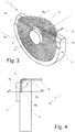
- Fig. 3 shows a perspective view of a ferrite core coil device 1 according to the invention.
- the ferrite core coil comprises a coil 2 supported on the ferrite core 3 of Fig. 1 .
- An output connector 6 of the coil is also visible in Fig. 3 , by means of which the coil 2 can be connected to external circuitry used to process the signal delivered by the coil device 1.
- the coil 2 is wound around pin 5 and has preferably between 10 and 30 windings. It is preferred that the coil occupies with no gaps substantially the entire surface between the edge wall 3b and the pin 5, whereas a radius R2 of the wound coil 2 is smaller than a radius R1 of the ferrite core 3.
- the coil 2 is divided into two sections, of which a first segment 2a of the coil is bent around and along the bending edge 4a (the chord).
- the coil 2 is bent in such a way that it substantially forms an L-shaped coil, best seen in Fig. 4 .
- a second segment 2b of the coil 2 rests on the bed 3a.
- a ratio between the first segment 2a of the coil 2 and the second segment 2b of the coil 2 is between 1 : 1 and 1.5 : 1.
- the pin 5 is preferably cylindrical.
- the pin may have a similar shape as the disk itself. This is particularly the case for the 1:1 ratio between the segments.
- the pin has a cross section of a half circle as seen up to the bending edge 4a.
- the dimensions in the example shown in Fig. 1 are such that the pin 5 is just still a full circle.
- the coil 2 is printed on a flexible polymer substrate.
- the material for the flexible polymer substrate is chosen to be highly heat-resistant, in particular to withstand temperatures at least up to 200°C, preferably at least up to 230°C. Suitable materials are for example liquid crystal polymers or polyimides.
- the flexible polymer substrate also protects the coil 2 against breakage as it may otherwise break due to its inherent fragility. Another advantage of this approach is the simplicity of the mounting process, as the coil doesn't have to be wound around pin 5 manually or by machine.
- Fig. 4 shows a side view of the ferrite core coil device of Fig. 3 , which emphasizes the L shape of the coil 2.
- the coil 2 is bent around and along the bending edge 4a, with the two thereby formed segments at a bending angle a with respect to one another.
- the bending angle a is between 70 and 110 degrees.
- the present example has been chosen with a bending angle of 90° which yield best results for the present exemplary application.
- An increase of the bending angle above 90° will result in a reduction of the signal amplitude, as the magnetic field is increasingly opposed.
- a reduction of the bending angle below 90° towards a flat pancake coil will result in the signal showing double-pulse behaviour at thin blades. These effects are particularly pronounced for blade thicknesses below 1 mm.
- the chord 4a which delimits the bed 3a, is regarded as a line where the bed 3a ends and a curvature of the bending area starts.
- This curvature which is illustrated by the curved area at the line 4a, is such that, taking into account the wire thickness of the coil 2, the bent area of the coil snuggles smoothly on this curved surface. In any case the curvature is not chosen too high such that no sharp edge is created, which could damage the coil wire or cause a folding of the coil wire, which is not desired.
- Fig. 5 shows a plot of output signals of different coil types according to the prior art in order to illustrate the problems outlined in the first section of this document.
- the plot shows the detection signal over time t for different blade thicknesses ranging in the example from 0.2 mm to 10 mm.
- the upper plot corresponds to a DD coil, the middle one to a pancake coil and the bottom plot to an L coil.
- the DD coil produces a good amplitude but is prone to double peaks for a wide range of thicknesses
- the pancake coil shows the poorest performance, with low amplitude and many double peaks
- the L coil is almost double-peak-free but also has a low amplitude, even if better than in case of the pancake coil.
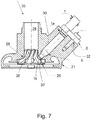
- Fig. 6 shows a sensor device 1a according to the invention with the ferrite core coil device 1 of Fig. 3 and Fig. 7 a detail cross-sectional view of the sensor tip 15 of the sensor device of Fig. 6 .
- the sensor device 1a for determining rotational speed of a rotatable object comprises a sensor housing (not shown) with a connector segment 7, a mounting segment 8 and a sensor segment 9.
- the abovementioned ferrite core coil device 1, i.e. the sensing element, is arranged at the sensor tip 15 of the sensor segment 9.
- Fig. 7 illustrates how the ferrite core coil device 1 is attached to the sensor segment 9 of the sensor device 1a at the line 10.
- the tip 15 of the sensor segment 9 has substantially the same surface as the ferrite core 3 in the present example, with a stepped section for accommodating the bent first segment 2a of the coil 2.
- the stepped design advantageously provides a support for the first segment 2a of the coil 2.
- the diameter of the sensor segment tip 15 must not necessarily match the diameter D1 of the coil device 1.
- the ferrite core coil device 1 is connected to sensor electronics for evaluating the output signal of the sensing element 1, which are arranged inside the sensor segment 9.
- the sensor electronics preferably comprise an integrated SOI (silicon-on-insulator) circuit, in particular in form of an ASIC. Use of such a SOI circuit has proved advantageous to the extent that it can withstand high temperatures and is therefore suitable for use in difficult environments like inside a turbocharger.
- SOI silicon-on-insulator
- the ASIC may be configured for the following parameters/features: number of blades (divider), debouncer, output pulse width, maximum frequency range of the output signal, error detection frequency range, detection threshold and hysteresis, short circuit detection time, over temperature shutdown threshold, oscillator trimming, demodulator trimming, bandgap trimming, and/or error flagging disabling and enabling.
- Error flagging disabling and enabling may especially concern: coil-break (breaking of the sensing element 15), overtemperature detection (regarding sensor device environment), data-integrity detection, overvoltage and undervoltage detection (e.g. to protect an engine control unit which the sensor device 20 is connected to), frequency error (e.g., whether compressor wheel speed is too low).
- a diagnosis function/system may be incorporated into the ASIC and configured in an application dependent way, the diagnosis system monitoring overvoltage and undervoltage, overtemperature, data integrity, frequency error, coil/sensing element breakage, and/or short circuits.
- Fig. 8 shows a cross-sectional view of a turbocharger 20 according to the invention with the incorporated sensor device 1a of Fig. 7 .
- the turbocharger 20 has a turbocharger housing 21.
- a compressor wheel 28 attached to a shaft with a compressor inlet 29 is arranged inside the turbocharger housing 30 and is connected to a turbine wheel by a shaft (not shown).
- a wall 30 (hashed area) of the turbocharger housing 30 is provided with a recess in which at least the sensor segment 9 of the sensor device 1a can be introduced and affixed in the intended operating position.
- the connector segment 7 of the sensor device 1a is connected to the sensor electronics for further processing the sensor signal.
- the mounting segment 8 is preferably formed as a flange with an insert hole through which a bolt or other securing means can be passed for secure attachment of the sensor device 1a on the outside of the turbocharger housing 21.
- the sensor segment 9 of the sensor device is positioned such that the sensor tip 15, i.e. the ferrite core coil device 1 of the sensor device 1a, faces the blades 26 of the compressor wheel 28, as shown in Fig. 8.
- the bore accommodating the sensor device 1a tapers towards the sensor tip 15 which may have a smaller diameter than the rest of the sensor device 1a. In this way it is made sure that the sensor tip is tightly fit into the tapered section of the bore.
- the sensing element 1 is part of an oscillator tank formed by the coil, a capacitor and the integrated SOI circuit/ASIC. This leads to the generation of an electromagnetic field around the sensing element 1, whose magnetic flux lines "step out" of the plane of the sensing element 1. If an electrically conducting target/object such as an impeller/compressor blade 26 approaches the sensing element 1, the magnetic flux lines pass through the blades 26 and induce eddy currents therein. The eddy currents within the blades 26 also generate an electromagnetic field counteracting the electromagnetic field generated by the sensing element 1, thereby affecting the impedance of the sensing element 1, and therefore the oscillation frequency. The eddy current effect increases when a blade 26 approaches the sensing element 1.
- the changing impedance of the sensing element 1 is reflected in modulation of the oscillation frequency. Evaluating this frequency by the sensor electronics and/or an engine control unit results in current or voltage signals that correspond to the rotational speed of the impeller/ compressor wheel blades 26, such that the rotational speed can be determined.
- the sensor device 1a is placed such that the sensor tip is at the predefined distance from the rotatable object.
- the tubular sensor device 1a is introduced into the recess in the wall of the turbocharger 20 and inserted therein until the sensor tip is at the specified distance from the impeller. This can be seen in Fig. 8 at the location indicated by arrow 37. Preferably, this distance is between 0.5 and 1 mm from the rotating impeller.
- an electrical input current is applied to the ferrite core coil device 1 and an amplitude modulated output voltage signal is read as output of the sensor device and processed by said sensor electronics.
- the sensor electronics determine the rotational speed of the impeller by evaluating a demodulated output voltage signal of the sensor device 7.
- the present invention improves the detection quality in applications tied to measurements of rotational speeds of rotating metallic objects by providing clean peaks for output signals, thereby eliminating or at least considerably reducing the undesired effect of double peaks. At the same time, it provides output signals with increased amplitude, such that no blade passage remains undetected.
Landscapes
- Engineering & Computer Science (AREA)
- Power Engineering (AREA)
- Physics & Mathematics (AREA)
- General Physics & Mathematics (AREA)
- Mechanical Engineering (AREA)
- General Engineering & Computer Science (AREA)
- Chemical & Material Sciences (AREA)
- Combustion & Propulsion (AREA)
- Supercharger (AREA)
- Transmission And Conversion Of Sensor Element Output (AREA)
- Combined Controls Of Internal Combustion Engines (AREA)
- Coils Or Transformers For Communication (AREA)
Description
- The invention relates to a ferrite core coil device, to a sensor device for determining rotational speed of a rotatable object, which sensor device comprises such a ferrite core coil device, and to a turbocharger with such a sensor device according to the independent claims.
- A turbocharger converts waste energy in the exhaust gas of an automotive engine into compressed air, which is then forced back into the automotive engine. This results in the engine burning more fuel and thus producing more power, while less energy is consumed, thereby improving the overall efficiency of the combustion process. A turbocharger typically comprises a turbine wheel and a compressor wheel, which are connected by a common shaft supported on a bearing system. The turbine wheel is driven by the exhaust gas which in turn drives the compressor wheel, the compressor wheel drawing in and compressing ambient air which is then fed into the engine's cylinders. By means of turbocharging the performance level of smaller engines can be increased up to the performance level of bigger engines without turbocharging, with lower fuel consumption and emissions. Consequently, turbochargers are increasingly employed with diesel and gasoline engines in passenger, commercial, off-road and sport vehicles.
- Determining rotational speed of the compressor wheel of a turbocharger is important for optimizing its efficiency, and for ensuring that a turbocharger and engine stay within their respective safe operational ranges. Today's turbochargers need to operate reliably and continuously with increasingly higher exhaust gas temperatures and compressor inlet temperatures. Compared with its diesel counterpart, a modern gasoline turbocharger has to operate in a much higher underhood temperature environment, with temperatures at the compressor wheel being around 200°C or above. Modern turbocharger compressor wheels are typically constructed from strong, lightweight conductive materials such as aluminum, titanium or magnesium which can tolerate high stresses. Rotational speed of such compressor wheels can be measured, preferably by means of an active eddy current principle, wherein a magnetic field is generated by an oscillating system and a sensing coil is used to detect compressor blades when they pass through the magnetic field in front of the sensor tip.
- Turbocharger speed sensors are often implemented by connecting a sensor head/sensor tip with the sensing element that is located close to the compressor wheel via a cable to the sensor electronics.
- Nowadays applications for measurement of turbocharger speed are challenging in that impeller/compressor wheels (the target wheels) are typically very thin (a few tenths of a millimeter; in particular for passenger cars) and therefore deliver a low signal. Also the sensing distance/air gap, i.e. the distance between the sensing element, typically a standard flat coil such as a pancake coil) and the target (the blades), varies as the coil is flat while the interior wall of the turbocharger housing is round/saddle-shaped and the envelope of the impeller/compressor wheel is curved.
- Generally speaking, amongst other factors, the coil type used as sensing element has a decisive impact on the detection signal shape. In order to reach a reliable rotation speed calculation, the detection signal should preferably exhibit an as sharp as possible signal peak with sufficient amplitude every time when a blade passes in front of the sensor tip. If for example the amplitude of the signal peak is not large enough (i.e. the signal is not strong enough), no peak may be detected, which in turn would lead to an erroneous rotation speed. Typically, the amplitude of the detection signal decreases with decreasing blade thickness, which consequently makes it more difficult to detect thin blades. Outer influences such as the casing of the device incorporating the sensor also play an important role and can produce signal amplitude modulation losses of up to 50%.
- Beside the problem of weak signals for thin blades, all these solutions have another common problem, which is the occurrence of so called "double peaks" in the detection signal. This means that one single peak may in fact show two peaks. This may also lead to an erroneous rotation speed as the system may interpret the double peaks as two distinct single peaks, that is: two blade passages instead of one.
- These two properties of the output signal of a sensing element for a turbocharger cause problems for available solutions to the extent that the measured rpm (rotations per minute) values may be erroneous.
- Document
US 2016/0187366 discloses a sensor device for determining rotational speed of a rotatable object. The sensor device comprises a sensor segment a mounting segment and a connector segment. The sensor segment comprises a sensor tip with a coil as sensing element for the rotation of the object and a SOI circuit embedded between polymer substrates, which SOI circuit comprises circuitry for handling signals from/to the sensor tip. This circuitry may comprise ferrites amongst other elements. - It is an object of the present invention to provide a sensing element for a sensor device and such a sensor device for determining rotational speed of a rotatable object, in particular of the compressor wheel of a turbocharger, that is more reliable and accurate with respect to the aforementioned problems, in particular su-presses the double peaks of the detection signal and maximizes the signal amplitude. It is a further object of the invention to provide a turbocharger with such a sensor device.
- In order to implement this object, and still further objects of the invention, which will become more readily apparent as the description proceeds, a ferrite core coil device as sensing element for a sensor device is provided in a first aspect of the invention. The sensor device is a speed sensor adapted for determining rotational speed of a rotatable metallic object. The ferrite core coil device comprises an electromagnetic coil and a ferrite core holding the coil. The ferrite core has a shape of a disk lacking a disk segment, thereby being defined by a contour of the disk and a chord of the disk. The chord forms a bending edge of the ferrite core. A first segment of the coil is not arranged on the bed and a second segment of the coil is arranged on the bed. The first segment is bent around the bending edge at a bending angle with respect to the second segment.
- A second aspect of the invention relates to a sensor device for determining rotational speed of a rotatable object, comprising a sensor housing with a sensor segment, a mounting segment and a connector segment. A ferrite core coil device according to the first aspect of the invention is arranged at the sensor tip of the sensor segment.
- A third aspect of the invention concerns a turbocharger with a turbocharger housing and a sensor device according to the second aspect of the invention. A compressor impeller is arranged inside the turbocharger housing and a wall of the turbocharger housing is provided with a recess in which at least the sensor segment of the sensor device is arranged such that the ferrite core coil device of the sensor device protrudes through the wall facing the impeller at a predefined distance from the compressor impeller. In embodiments, this distance is preferably between 0.5 and 1 mm.
- In yet a fourth aspect of the invention, a method for determining rotational speed of a rotatable object employs a sensor device according to the second aspect of the invention. The method comprises the steps of:
- placing the sensor device such that the sensor tip is at a predefined distance from the rotating object,
- applying an electrical input current to the ferrite core coil device,
- reading an amplitude modulated output voltage signal as output of the sensor device, and
- determining the rotational speed by evaluating a demodulated output voltage signal of the sensor device.
- The sensor device of the invention may be used for turbocharger compression wheel blade sensing for example in automotive, truck, off-highway vehicle, aerospace or power generation applications. The sensor device of the invention may furthermore be used in any application where rotational speed needs to be measured/detected, in particular in applications of small size and/or with high ambient temperatures and/or where target/object materials are of lower electrical conductivity than aluminium (e.g., impeller blades with thin geometry made of for example titanium). But the invention may be integrated in all types of industrial machines containing rotating parts, e.g. in manufacturing lines, etc., particularly for applications requiring a high reliability of rotating parts.
- The turbocharger according to the third aspect of the invention is preferably used in automobile motors but may also be used for other applications particularly related to propulsion technologies including aerospace, etc.
- It has been found that by using a ferrite core together with an L coil, the signal amplitude can be increased, whereas the ferrite core acts like an amplifier of the detection signal. Thereby, a more reliable differentiation between distinct "real" signal peaks is reached. Yet another advantage of using the ferrite core is that the core at the same time provides a good support for the coil, which will be described further down in the context of a preferred embodiment of the ferrite core coil device.
- At the same time, the shape and relative arrangement of the coil and ferrite core of a sensor device as claimed makes it possible to avoid double peaks entirely (even for thin coils of ca. 0.2 mm) and advantageously reach an increased sensor sensitivity as compared to known sensors and makes possible a better and even error-free signal peak detection. Thereby the risk of false assumption (detection) of the presence of two signal peaks (i.e. two blade passages) instead of one is minimized or avoided.
- Furthermore, the increased sensor sensitivity allows to increase the distance between the sensor device and the blade, i.e. the air gap, thereby simplifying the production process, as positioning of the sensor requires less accuracy than in known solutions.
- Further advantageous features and applications of the invention can be found in the dependent claims, as well as in the following description of the drawings illustrating the invention. In the drawings same reference signs designate the same or similar parts/components throughout the several figures of which:
-
Fig. 1 shows a perspective view of a ferrite core for a ferrite core coil device according to the invention, -
Fig. 2 shows a top view of the ferrite core ofFig. 1 , -
Fig. 3 shows a perspective view of a ferrite core coil device according to the invention, -
Fig. 4 shows a side view of the ferrite core coil device ofFig. 3 , -
Fig. 5 shows a plot of output signals of different known coil types, -
Fig. 6 shows a sensor device according to the invention with the ferrite core coil device ofFig. 3 , -
Fig. 7 shows a detail cross-sectional view of thesensor tip 15 of the sensor device ofFig. 6 , - Fig. 8 shows a cross-sectional view of a turbocharger according to the invention with the incorporated sensor device of
Fig. 7 . - Definitions:
For the purposes of the invention, a rotatable object may e.g. be a compressor wheel of a turbocharger as for example used in automobiles, but shall not be limited thereto. The invention may also be applied to a variety of rotating objects, provided that these objects are made of a metal suitable for the detection method described herein or contain a sufficient amount of such metal. - The term "metallic" in connection with the rotatable object is understood here as encompassing a metal or a metal alloy, but the rotatable object may also comprise other materials like plastic, in general provided that the metal amount/conductivity is sufficient for triggering detectable signal peaks with the invention.
- The term "chord" used throughout this document is understood in its mathematical sense as a "chord of a circle" and is hence defined as a line segment whose endpoints both lie on the circle. However, for the purposes of the invention the term chord shall also imply a curved line with a curvature larger than the curvature of the circle cut by the chord (i.e. with a smaller radius than the radius of the circle).
- The term "radius" is used here as seen from the central axis x of the ferrite core coil device.
-
Fig. 1 shows a perspective view of aferrite core 3 for a ferrite core coil device 1 (Fig. 3 ) according to the invention andFig. 2 shows a top view of theferrite core 3 ofFig. 1 . Theferrite core 3 has the shape of a disk without a disk segment, with a maximum diameter D1. Theferrite core 3 is delimited by the contour of the disk and by achord 4a of the disk. Hence, a size of the remaining disk segment is defined by a distance of thechord 4a from a central axis x of the ferritecore coil device 1. Theferrite core 3 also has abed 3a as a surface for placing a coil 2 (Fig. 3 ), whichbed 3a has a maximum diameter D2. Thebed 3a is delimited by anedge wall 3b of theferrite core 3, which extends along said contour of the disk, and by thechord 4a which marks a bending edge of theferrite core 3. Theedge wall 3b therefore has a thickness given by D1 - D2. - The
ferrite core 3 preferably has apin 5 which protrudes from thebed 3a. It is preferred that thepin 5 has a circular cross-section with diameter D3 and therefore an overall cylindrical shape. It preferably has the same axis as theferrite core 3. Thepin 5 has substantially asame height 4b from thebed 3a as theedge wall 3b but it can also slightly exceed theheight 4b of theedge wall 3b. It is noted that the ferritecore coil device 1 may be used without thepin 5. However it has been found that usage ofpin 5 increases performance of the coil device. Furthermore, the attachment of the coil is more robust as the coil can't shift. - In preferred embodiments, the
ferrite core 3 has a thickness between 0.2 mm and 2 mm. - In preferred embodiments, the
ferrite core 3 has a permeability µr between 50 and 3000. -
Fig. 3 shows a perspective view of a ferritecore coil device 1 according to the invention. The ferrite core coil comprises acoil 2 supported on theferrite core 3 ofFig. 1 . Anoutput connector 6 of the coil is also visible inFig. 3 , by means of which thecoil 2 can be connected to external circuitry used to process the signal delivered by thecoil device 1. - The
coil 2 is wound aroundpin 5 and has preferably between 10 and 30 windings. It is preferred that the coil occupies with no gaps substantially the entire surface between theedge wall 3b and thepin 5, whereas a radius R2 of thewound coil 2 is smaller than a radius R1 of theferrite core 3. - The
coil 2 is divided into two sections, of which afirst segment 2a of the coil is bent around and along the bendingedge 4a (the chord). Thecoil 2 is bent in such a way that it substantially forms an L-shaped coil, best seen inFig. 4 . Asecond segment 2b of thecoil 2 rests on thebed 3a. A ratio between thefirst segment 2a of thecoil 2 and thesecond segment 2b of thecoil 2 is between 1 : 1 and 1.5 : 1. As mentioned before, thepin 5 is preferably cylindrical. Depending on the ratio between the two segments of thecoil 2, which indirectly may define dimensions of theferrite core 3 as well, the pin may have a similar shape as the disk itself. This is particularly the case for the 1:1 ratio between the segments. In this case the pin has a cross section of a half circle as seen up to the bendingedge 4a. The dimensions in the example shown inFig. 1 are such that thepin 5 is just still a full circle. - In embodiments, the
coil 2 is printed on a flexible polymer substrate. The material for the flexible polymer substrate is chosen to be highly heat-resistant, in particular to withstand temperatures at least up to 200°C, preferably at least up to 230°C. Suitable materials are for example liquid crystal polymers or polyimides. The flexible polymer substrate also protects thecoil 2 against breakage as it may otherwise break due to its inherent fragility. Another advantage of this approach is the simplicity of the mounting process, as the coil doesn't have to be wound aroundpin 5 manually or by machine. -
Fig. 4 shows a side view of the ferrite core coil device ofFig. 3 , which emphasizes the L shape of thecoil 2. As mentioned, thecoil 2 is bent around and along the bendingedge 4a, with the two thereby formed segments at a bending angle a with respect to one another. Preferably, the bending angle a is between 70 and 110 degrees. The present example has been chosen with a bending angle of 90° which yield best results for the present exemplary application. An increase of the bending angle above 90° will result in a reduction of the signal amplitude, as the magnetic field is increasingly opposed. A reduction of the bending angle below 90° towards a flat pancake coil will result in the signal showing double-pulse behaviour at thin blades. These effects are particularly pronounced for blade thicknesses below 1 mm. - The
chord 4a, which delimits thebed 3a, is regarded as a line where thebed 3a ends and a curvature of the bending area starts. This curvature, which is illustrated by the curved area at theline 4a, is such that, taking into account the wire thickness of thecoil 2, the bent area of the coil snuggles smoothly on this curved surface. In any case the curvature is not chosen too high such that no sharp edge is created, which could damage the coil wire or cause a folding of the coil wire, which is not desired. -
Fig. 5 shows a plot of output signals of different coil types according to the prior art in order to illustrate the problems outlined in the first section of this document. - In known applications relatively large coils are employed to obtain a strong enough output signal. However, in turbocharger applications there is a need for small sensing elements/coils to permit a small/thin sensor device tip in order to avoid negative side effects such as hot spots and aerodynamic disturbances which may have a negative impact on the turbocharger's functioning.
- With a large flat coil used in available solutions disturbing effects of varying sensing distance/air gap are even stronger. Furthermore, sensor tips with such a large coil are too big to be inserted into small turbochargers of the new generation.
- The plot shows the detection signal over time t for different blade thicknesses ranging in the example from 0.2 mm to 10 mm. The upper plot corresponds to a DD coil, the middle one to a pancake coil and the bottom plot to an L coil.
- When analyzing the plots with respect to signal amplitude it is clear that
- DD (or double-D) coils produce a sharp and narrow detection signal across a wide range of blade thicknesses, at least down to 0.2 mm thick blades, thereby exhibiting an acceptable amplitude even for very thin blades.
- Flat or pancake coils exhibit a good signal performance for thicker blades between 10 and 4 mm. However, for thinner blades the signal amplitude drops sharply and is roughly half the amplitude for a comparative DD coil.
- L coils are comparable with the DD and pancake coils for thick blades. They exhibit a sharp signal, with the signal peak width (sharpness) residing somewhere between the peak width of the DD coils and the pancake coils.
- Consequently, in terms of amplitude all coil types perform relatively well for thick blades but differ primarily in their behavior in the presence of thin blades.
- When analyzing the plots with respect to double peaks it is clear that the double peaks only occur for certain blade thicknesses, which varies depending on coil type. For example, DD coils have double peaks for blade thicknesses between 0.8 mm and 2 mm. Pancake coils have double peaks between 0.2 and 0.4 mm. L coils almost don't have double peaks except for a weak one for blades with approximately 0.2 mm thickness.
- One can see that every type of coil has its advantages and disadvantages; the DD coil produces a good amplitude but is prone to double peaks for a wide range of thicknesses; the pancake coil shows the poorest performance, with low amplitude and many double peaks; the L coil is almost double-peak-free but also has a low amplitude, even if better than in case of the pancake coil.
-
Fig. 6 shows asensor device 1a according to the invention with the ferritecore coil device 1 ofFig. 3 andFig. 7 a detail cross-sectional view of thesensor tip 15 of the sensor device ofFig. 6 . Thesensor device 1a for determining rotational speed of a rotatable object comprises a sensor housing (not shown) with aconnector segment 7, a mountingsegment 8 and asensor segment 9. The abovementioned ferritecore coil device 1, i.e. the sensing element, is arranged at thesensor tip 15 of thesensor segment 9.Fig. 7 illustrates how the ferritecore coil device 1 is attached to thesensor segment 9 of thesensor device 1a at theline 10. For this purpose thetip 15 of thesensor segment 9 has substantially the same surface as theferrite core 3 in the present example, with a stepped section for accommodating the bentfirst segment 2a of thecoil 2. The stepped design advantageously provides a support for thefirst segment 2a of thecoil 2. The diameter of thesensor segment tip 15 must not necessarily match the diameter D1 of thecoil device 1. - The ferrite
core coil device 1 is connected to sensor electronics for evaluating the output signal of thesensing element 1, which are arranged inside thesensor segment 9. The sensor electronics preferably comprise an integrated SOI (silicon-on-insulator) circuit, in particular in form of an ASIC. Use of such a SOI circuit has proved advantageous to the extent that it can withstand high temperatures and is therefore suitable for use in difficult environments like inside a turbocharger. - In particular, the ASIC may be configured for the following parameters/features: number of blades (divider), debouncer, output pulse width, maximum frequency range of the output signal, error detection frequency range, detection threshold and hysteresis, short circuit detection time, over temperature shutdown threshold, oscillator trimming, demodulator trimming, bandgap trimming, and/or error flagging disabling and enabling. Error flagging disabling and enabling may especially concern: coil-break (breaking of the sensing element 15), overtemperature detection (regarding sensor device environment), data-integrity detection, overvoltage and undervoltage detection (e.g. to protect an engine control unit which the
sensor device 20 is connected to), frequency error (e.g., whether compressor wheel speed is too low). - Thus, a diagnosis function/system may be incorporated into the ASIC and configured in an application dependent way, the diagnosis system monitoring overvoltage and undervoltage, overtemperature, data integrity, frequency error, coil/sensing element breakage, and/or short circuits.
- Fig. 8 shows a cross-sectional view of a
turbocharger 20 according to the invention with the incorporatedsensor device 1a ofFig. 7 . Furthermore, theturbocharger 20 has aturbocharger housing 21. Acompressor wheel 28 attached to a shaft with acompressor inlet 29 is arranged inside theturbocharger housing 30 and is connected to a turbine wheel by a shaft (not shown). A wall 30 (hashed area) of theturbocharger housing 30 is provided with a recess in which at least thesensor segment 9 of thesensor device 1a can be introduced and affixed in the intended operating position. - The
connector segment 7 of thesensor device 1a is connected to the sensor electronics for further processing the sensor signal. - The mounting
segment 8 is preferably formed as a flange with an insert hole through which a bolt or other securing means can be passed for secure attachment of thesensor device 1a on the outside of theturbocharger housing 21. - The
sensor segment 9 of the sensor device is positioned such that thesensor tip 15, i.e. the ferritecore coil device 1 of thesensor device 1a, faces theblades 26 of thecompressor wheel 28, as shown in Fig. 8. In embodiments, the bore accommodating thesensor device 1a tapers towards thesensor tip 15 which may have a smaller diameter than the rest of thesensor device 1a. In this way it is made sure that the sensor tip is tightly fit into the tapered section of the bore. - In the following, the method for installation and operation of the
sensor device 1a is described in more detail in connection with the underlying measurement principle of the ferritecore coil device 1, which was shortly outlined at the beginning. - For measuring rotational speed of the
compressor wheel 28, thesensing element 1 is part of an oscillator tank formed by the coil, a capacitor and the integrated SOI circuit/ASIC. This leads to the generation of an electromagnetic field around thesensing element 1, whose magnetic flux lines "step out" of the plane of thesensing element 1. If an electrically conducting target/object such as an impeller/compressor blade 26 approaches thesensing element 1, the magnetic flux lines pass through theblades 26 and induce eddy currents therein. The eddy currents within theblades 26 also generate an electromagnetic field counteracting the electromagnetic field generated by thesensing element 1, thereby affecting the impedance of thesensing element 1, and therefore the oscillation frequency. The eddy current effect increases when ablade 26 approaches thesensing element 1. The changing impedance of thesensing element 1 is reflected in modulation of the oscillation frequency. Evaluating this frequency by the sensor electronics and/or an engine control unit results in current or voltage signals that correspond to the rotational speed of the impeller/compressor wheel blades 26, such that the rotational speed can be determined. - As mentioned, the
sensor device 1a is placed such that the sensor tip is at the predefined distance from the rotatable object. In the specific example of the turbocharger of Fig. 8, thetubular sensor device 1a is introduced into the recess in the wall of theturbocharger 20 and inserted therein until the sensor tip is at the specified distance from the impeller. This can be seen in Fig. 8 at the location indicated byarrow 37. Preferably, this distance is between 0.5 and 1 mm from the rotating impeller. - Generally, after connecting the sensor to the sensor electronics for further processing, an electrical input current is applied to the ferrite
core coil device 1 and an amplitude modulated output voltage signal is read as output of the sensor device and processed by said sensor electronics. The sensor electronics determine the rotational speed of the impeller by evaluating a demodulated output voltage signal of thesensor device 7. - The present invention improves the detection quality in applications tied to measurements of rotational speeds of rotating metallic objects by providing clean peaks for output signals, thereby eliminating or at least considerably reducing the undesired effect of double peaks. At the same time, it provides output signals with increased amplitude, such that no blade passage remains undetected.
- It is to be understood that while certain embodiments of the present invention have been illustrated and described herein, it is not to be limited to the specific embodiments described and shown. Therefore, terms like "preferred" or "in particular" or "particularly" or "advantageously", etc. signify optional and exemplary embodiments only.
Claims (15)
- Ferrite core coil device (1) as sensing element for a sensor device (1a) for determining rotational speed of a metallic rotatable object (28), characterized in that the ferrite core coil comprises an electromagnetic coil (2) and a ferrite core (3) having a bed (3a) for holding the coil (2),
wherein the ferrite core (3) has a shape of a disk lacking a disk segment, thereby having a shape defined by a contour of the disk and a chord (4a) of the disk,
wherein the chord forms a bending edge (4a) of the ferrite core (3),
wherein a first segment (2a) of the coil (2) is not arranged on the bed (3a) and a second segment (2b) of the coil (2) is arranged on the bed (3a),
wherein the first segment (2a) is bent around the bending edge (4a) at a bending angle (a) with respect to the second segment (2b). - Ferrite core coil device according to claim 1, wherein the ferrite core has a pin (5) protruding from the bed (3a), particularly wherein the pin (5) has a same axis (x) as the ferrite core (3), wherein the coil (2) is wound around the pin (5).
- Ferrite core coil device according to claim 1 or 2, wherein the bed (3a) is delimited by a supporting edge wall (3b) of the ferrite core (3), which extends along said contour of the disk, and by the bending edge (4a).
- Ferrite core coil device according to claim 2 and 3, wherein the pin (5) has substantially a same height from the bed (3a) like the edge wall (3b).
- Ferrite core coil device according to one of the preceding claims, wherein a radius (R2) of the wound coil is smaller than a radius (R1) of the ferrite core (3).
- Ferrite core coil device according to one of the preceding claims, wherein a ratio between the first segment (2a) of the coil (2) and the second segment (2b) of the coil (2) is between 1 : 1 and 1.5 : 1.
- Ferrite core coil device according to one of the preceding claims, wherein the bending angle (a) is between 70 and 110 degrees, particularly wherein the coil (2) is a substantially L-shaped coil with a bending angle of 90°.
- Ferrite core coil device according to one of the preceding claims, wherein the coil (2) has between 10 and 30 windings.
- Ferrite core coil device according to one of the preceding claims, wherein the coil (2) is wound such that all windings of the coil (2) are in contact with the bed (3a).
- Ferrite core coil device according to one of the preceding claims, wherein the coil (2) is printed on a flexible polymer substrate.
- Ferrite core coil device according to one of the preceding claims, wherein the ferrite core (3) has a thickness between 0.2 mm and 2 mm.
- Ferrite core coil device according to one of the preceding claims, wherein the ferrite core (3) has a permeability µr between 50 and 3000.
- Sensor device (1a) for determining rotational speed of a rotatable object (28), comprising a sensor housing with a sensor segment (9), a mounting segment (8) and a connector segment (7), wherein a ferrite core coil device (1) according to one of the preceding claims is arranged at a sensor tip (15) of the sensor segment (9).
- Turbocharger (20) with a turbocharger housing (21) and a sensor device (1a) according to claim 13, wherein a compressor impeller (28) is arranged inside the turbocharger housing (21) and a wall (30) of the turbocharger housing (21) is provided with a recess in which at least the sensor segment (9) of the sensor device (1a) is arranged such that the ferrite core coil device (1) of the sensor device (1a) protrudes through the wall (30) facing the impeller (28) at a predefined distance (37) from the compressor impeller (28), particularly at a distance between 0.5 and 1 mm.
- Method for determining rotational speed of a rotatable object, particularly a turbocharger blade, with a sensor device (1a) according to claim 13, comprising the steps ofplacing the sensor device (1a) such that the sensor tip (15) is at a predefined distance (37) from the rotating object (28),applying an electrical input current to the ferrite core coil device (1),reading an amplitude modulated output voltage signal as output of the sensor device (1a), anddetermining the rotational speed by evaluating a demodulated output voltage signal of the sensor device (1a).
Priority Applications (5)
| Application Number | Priority Date | Filing Date | Title |
|---|---|---|---|
| EP19182660.1A EP3757354B1 (en) | 2019-06-26 | 2019-06-26 | Ferrite core coil device, sensor device for determining rotational speed of a rotatable object with such a ferrite core coil device and turbocharger with such a sensor device |
| KR1020200075237A KR20210002335A (en) | 2019-06-26 | 2020-06-19 | Ferrite core coil device, sensor device for determining rotational speed of a rotatable object with such a ferrite core coil device and turbocharger with such a sensor device |
| JP2020105718A JP7416668B2 (en) | 2019-06-26 | 2020-06-19 | A ferrite core coil device, a sensor device for determining the rotational speed of a rotatable object comprising such a ferrite core coil device, and a turbocharger comprising such a sensor device |
| CN202010582893.0A CN112151247B (en) | 2019-06-26 | 2020-06-23 | Ferrite core coil device, sensor device, and turbocharger |
| US16/911,533 US11448660B2 (en) | 2019-06-26 | 2020-06-25 | Ferrite core coil device, sensor device for determining rotational speed of a rotatable object with such a ferrite core coil device and turbocharger with such a sensor device |
Applications Claiming Priority (1)
| Application Number | Priority Date | Filing Date | Title |
|---|---|---|---|
| EP19182660.1A EP3757354B1 (en) | 2019-06-26 | 2019-06-26 | Ferrite core coil device, sensor device for determining rotational speed of a rotatable object with such a ferrite core coil device and turbocharger with such a sensor device |
Publications (2)
| Publication Number | Publication Date |
|---|---|
| EP3757354A1 EP3757354A1 (en) | 2020-12-30 |
| EP3757354B1 true EP3757354B1 (en) | 2022-01-05 |
Family
ID=67352477
Family Applications (1)
| Application Number | Title | Priority Date | Filing Date |
|---|---|---|---|
| EP19182660.1A Active EP3757354B1 (en) | 2019-06-26 | 2019-06-26 | Ferrite core coil device, sensor device for determining rotational speed of a rotatable object with such a ferrite core coil device and turbocharger with such a sensor device |
Country Status (5)
| Country | Link |
|---|---|
| US (1) | US11448660B2 (en) |
| EP (1) | EP3757354B1 (en) |
| JP (1) | JP7416668B2 (en) |
| KR (1) | KR20210002335A (en) |
| CN (1) | CN112151247B (en) |
Family Cites Families (15)
| Publication number | Priority date | Publication date | Assignee | Title |
|---|---|---|---|---|
| DE3105356A1 (en) * | 1981-02-13 | 1982-09-02 | Transformatoren Union Ag, 7000 Stuttgart | Radially laminated iron core for inductor coils |
| AU7967794A (en) * | 1993-10-06 | 1995-05-01 | Kelsey-Hayes Company | Integral variable reluctance speed sensor |
| DE102004061260A1 (en) * | 2004-12-20 | 2006-06-29 | Robert Bosch Gmbh | magnetic field sensor |
| JP5240888B2 (en) | 2006-01-25 | 2013-07-17 | 株式会社日本自動車部品総合研究所 | Motion detection device |
| JP4846395B2 (en) | 2006-03-10 | 2011-12-28 | 株式会社デンソー | Motion detection device |
| JP2010056996A (en) | 2008-08-29 | 2010-03-11 | Koyo Electronics Ind Co Ltd | Amplifier integration type and amplifier discretion type proximity sensor |
| JP2010230593A (en) * | 2009-03-27 | 2010-10-14 | Sumitomo Wiring Syst Ltd | Wheel rotation sensor apparatus |
| DE102012200092A1 (en) * | 2012-01-04 | 2013-07-04 | Robert Bosch Gmbh | Sensor device for non-contact detection of a rotational property of a rotatable object |
| DE102012222202A1 (en) | 2012-12-04 | 2014-06-05 | Robert Bosch Gmbh | Method for monitoring a rotation of a compressor wheel |
| JP2015046463A (en) | 2013-08-28 | 2015-03-12 | 株式会社村田製作所 | Flexible wiring board |
| WO2015027348A1 (en) * | 2013-08-29 | 2015-03-05 | Jaquet Technology Group Ag | Sensor device for determining rotational speed of a rotatable object and turbocharger with such a sensor device |
| DE102014217272A1 (en) * | 2013-12-17 | 2015-06-18 | Robert Bosch Gmbh | Induction charging device |
| JP6544208B2 (en) * | 2015-11-09 | 2019-07-17 | 日立金属株式会社 | Turbocharger |
| JP2018013421A (en) | 2016-07-21 | 2018-01-25 | 日立金属株式会社 | Rotation detector for turbocharger |
| CN206516463U (en) * | 2016-11-18 | 2017-09-22 | 普洛西电源有限公司 | The device provided for the winding for enabling non-integer number on inductor |
-
2019
- 2019-06-26 EP EP19182660.1A patent/EP3757354B1/en active Active
-
2020
- 2020-06-19 KR KR1020200075237A patent/KR20210002335A/en active Pending
- 2020-06-19 JP JP2020105718A patent/JP7416668B2/en active Active
- 2020-06-23 CN CN202010582893.0A patent/CN112151247B/en active Active
- 2020-06-25 US US16/911,533 patent/US11448660B2/en active Active
Also Published As
| Publication number | Publication date |
|---|---|
| EP3757354A1 (en) | 2020-12-30 |
| US11448660B2 (en) | 2022-09-20 |
| US20200408796A1 (en) | 2020-12-31 |
| JP7416668B2 (en) | 2024-01-17 |
| CN112151247B (en) | 2025-06-17 |
| CN112151247A (en) | 2020-12-29 |
| JP2021005705A (en) | 2021-01-14 |
| KR20210002335A (en) | 2021-01-07 |
Similar Documents
| Publication | Publication Date | Title |
|---|---|---|
| EP3039433B1 (en) | Sensor device for determining rotational speed of a rotatable object and turbocharger with such a sensor device | |
| US9921081B2 (en) | Method for monitoring a rotation of a compressor wheel | |
| EP1314957B1 (en) | Method and apparatus for measuring turbine blade tip clearance | |
| US6323641B1 (en) | Non-contacting position sensor with helical flux linkage | |
| US8513960B2 (en) | Probe for a capacitive sensor device and gap-measuring system | |
| EP3221678B1 (en) | Temperature and angular speed sensing apparatus | |
| JP2008506074A (en) | Exhaust gas turbocharger | |
| US20140366632A1 (en) | sensor device for the contactless acquisition of a rotation characteristic of a rotatable object | |
| US7170284B2 (en) | Blade detection sensor having an active cooling system | |
| US20150233735A1 (en) | Sensor device for acquiring at least one rotational property of a rotating element | |
| JP5645207B2 (en) | Eddy current sensor and turbocharger rotation detection device using the same | |
| US6927567B1 (en) | Passive eddy current blade detection sensor | |
| US11448660B2 (en) | Ferrite core coil device, sensor device for determining rotational speed of a rotatable object with such a ferrite core coil device and turbocharger with such a sensor device | |
| US7417398B2 (en) | Vacuum pump | |
| US20180230846A1 (en) | Turbo rotation sensor and turbocharger | |
| JP6452060B1 (en) | Turbocharger | |
| JP3264833B2 (en) | Abnormality judgment device for magnetic protrusions | |
| JP2005265790A (en) | Rotor detecting sensor | |
| JPS6020049Y2 (en) | Rotational speed detection device for internal combustion engine | |
| US20190361043A1 (en) | Turbo rotation sensor | |
| JP2019207218A (en) | Turbo rotation sensor | |
| JP2007198821A (en) | Motion detection device | |
| JPS5858473A (en) | Rotation detector |
Legal Events
| Date | Code | Title | Description |
|---|---|---|---|
| PUAI | Public reference made under article 153(3) epc to a published international application that has entered the european phase |
Free format text: ORIGINAL CODE: 0009012 |
|
| STAA | Information on the status of an ep patent application or granted ep patent |
Free format text: STATUS: THE APPLICATION HAS BEEN PUBLISHED |
|
| AK | Designated contracting states |
Kind code of ref document: A1 Designated state(s): AL AT BE BG CH CY CZ DE DK EE ES FI FR GB GR HR HU IE IS IT LI LT LU LV MC MK MT NL NO PL PT RO RS SE SI SK SM TR |
|
| AX | Request for extension of the european patent |
Extension state: BA ME |
|
| STAA | Information on the status of an ep patent application or granted ep patent |
Free format text: STATUS: REQUEST FOR EXAMINATION WAS MADE |
|
| 17P | Request for examination filed |
Effective date: 20210603 |
|
| RBV | Designated contracting states (corrected) |
Designated state(s): AL AT BE BG CH CY CZ DE DK EE ES FI FR GB GR HR HU IE IS IT LI LT LU LV MC MK MT NL NO PL PT RO RS SE SI SK SM TR |
|
| RIC1 | Information provided on ipc code assigned before grant |
Ipc: F01D 11/20 20060101ALN20210924BHEP Ipc: H01F 5/00 20060101ALI20210924BHEP Ipc: H01F 3/08 20060101ALI20210924BHEP Ipc: G01P 3/488 20060101ALI20210924BHEP Ipc: F01D 21/00 20060101ALI20210924BHEP Ipc: F01D 17/06 20060101AFI20210924BHEP |
|
| GRAP | Despatch of communication of intention to grant a patent |
Free format text: ORIGINAL CODE: EPIDOSNIGR1 |
|
| STAA | Information on the status of an ep patent application or granted ep patent |
Free format text: STATUS: GRANT OF PATENT IS INTENDED |
|
| RIC1 | Information provided on ipc code assigned before grant |
Ipc: F01D 11/20 20060101ALN20211021BHEP Ipc: H01F 5/00 20060101ALI20211021BHEP Ipc: H01F 3/08 20060101ALI20211021BHEP Ipc: G01P 3/488 20060101ALI20211021BHEP Ipc: F01D 21/00 20060101ALI20211021BHEP Ipc: F01D 17/06 20060101AFI20211021BHEP |
|
| GRAS | Grant fee paid |
Free format text: ORIGINAL CODE: EPIDOSNIGR3 |
|
| GRAA | (expected) grant |
Free format text: ORIGINAL CODE: 0009210 |
|
| STAA | Information on the status of an ep patent application or granted ep patent |
Free format text: STATUS: THE PATENT HAS BEEN GRANTED |
|
| INTG | Intention to grant announced |
Effective date: 20211110 |
|
| AK | Designated contracting states |
Kind code of ref document: B1 Designated state(s): AL AT BE BG CH CY CZ DE DK EE ES FI FR GB GR HR HU IE IS IT LI LT LU LV MC MK MT NL NO PL PT RO RS SE SI SK SM TR |
|
| REG | Reference to a national code |
Ref country code: GB Ref legal event code: FG4D |
|
| REG | Reference to a national code |
Ref country code: CH Ref legal event code: EP |
|
| REG | Reference to a national code |
Ref country code: AT Ref legal event code: REF Ref document number: 1460785 Country of ref document: AT Kind code of ref document: T Effective date: 20220115 |
|
| REG | Reference to a national code |
Ref country code: DE Ref legal event code: R096 Ref document number: 602019010589 Country of ref document: DE |
|
| REG | Reference to a national code |
Ref country code: IE Ref legal event code: FG4D |
|
| REG | Reference to a national code |
Ref country code: LT Ref legal event code: MG9D |
|
| REG | Reference to a national code |
Ref country code: NL Ref legal event code: MP Effective date: 20220105 |
|
| REG | Reference to a national code |
Ref country code: AT Ref legal event code: MK05 Ref document number: 1460785 Country of ref document: AT Kind code of ref document: T Effective date: 20220105 |
|
| PG25 | Lapsed in a contracting state [announced via postgrant information from national office to epo] |
Ref country code: NL Free format text: LAPSE BECAUSE OF FAILURE TO SUBMIT A TRANSLATION OF THE DESCRIPTION OR TO PAY THE FEE WITHIN THE PRESCRIBED TIME-LIMIT Effective date: 20220105 |
|
| PG25 | Lapsed in a contracting state [announced via postgrant information from national office to epo] |
Ref country code: SE Free format text: LAPSE BECAUSE OF FAILURE TO SUBMIT A TRANSLATION OF THE DESCRIPTION OR TO PAY THE FEE WITHIN THE PRESCRIBED TIME-LIMIT Effective date: 20220105 Ref country code: RS Free format text: LAPSE BECAUSE OF FAILURE TO SUBMIT A TRANSLATION OF THE DESCRIPTION OR TO PAY THE FEE WITHIN THE PRESCRIBED TIME-LIMIT Effective date: 20220105 Ref country code: PT Free format text: LAPSE BECAUSE OF FAILURE TO SUBMIT A TRANSLATION OF THE DESCRIPTION OR TO PAY THE FEE WITHIN THE PRESCRIBED TIME-LIMIT Effective date: 20220505 Ref country code: NO Free format text: LAPSE BECAUSE OF FAILURE TO SUBMIT A TRANSLATION OF THE DESCRIPTION OR TO PAY THE FEE WITHIN THE PRESCRIBED TIME-LIMIT Effective date: 20220405 Ref country code: LT Free format text: LAPSE BECAUSE OF FAILURE TO SUBMIT A TRANSLATION OF THE DESCRIPTION OR TO PAY THE FEE WITHIN THE PRESCRIBED TIME-LIMIT Effective date: 20220105 Ref country code: HR Free format text: LAPSE BECAUSE OF FAILURE TO SUBMIT A TRANSLATION OF THE DESCRIPTION OR TO PAY THE FEE WITHIN THE PRESCRIBED TIME-LIMIT Effective date: 20220105 Ref country code: ES Free format text: LAPSE BECAUSE OF FAILURE TO SUBMIT A TRANSLATION OF THE DESCRIPTION OR TO PAY THE FEE WITHIN THE PRESCRIBED TIME-LIMIT Effective date: 20220105 Ref country code: BG Free format text: LAPSE BECAUSE OF FAILURE TO SUBMIT A TRANSLATION OF THE DESCRIPTION OR TO PAY THE FEE WITHIN THE PRESCRIBED TIME-LIMIT Effective date: 20220405 |
|
| PG25 | Lapsed in a contracting state [announced via postgrant information from national office to epo] |
Ref country code: PL Free format text: LAPSE BECAUSE OF FAILURE TO SUBMIT A TRANSLATION OF THE DESCRIPTION OR TO PAY THE FEE WITHIN THE PRESCRIBED TIME-LIMIT Effective date: 20220105 Ref country code: LV Free format text: LAPSE BECAUSE OF FAILURE TO SUBMIT A TRANSLATION OF THE DESCRIPTION OR TO PAY THE FEE WITHIN THE PRESCRIBED TIME-LIMIT Effective date: 20220105 Ref country code: GR Free format text: LAPSE BECAUSE OF FAILURE TO SUBMIT A TRANSLATION OF THE DESCRIPTION OR TO PAY THE FEE WITHIN THE PRESCRIBED TIME-LIMIT Effective date: 20220406 Ref country code: FI Free format text: LAPSE BECAUSE OF FAILURE TO SUBMIT A TRANSLATION OF THE DESCRIPTION OR TO PAY THE FEE WITHIN THE PRESCRIBED TIME-LIMIT Effective date: 20220105 Ref country code: AT Free format text: LAPSE BECAUSE OF FAILURE TO SUBMIT A TRANSLATION OF THE DESCRIPTION OR TO PAY THE FEE WITHIN THE PRESCRIBED TIME-LIMIT Effective date: 20220105 |
|
| PG25 | Lapsed in a contracting state [announced via postgrant information from national office to epo] |
Ref country code: IS Free format text: LAPSE BECAUSE OF FAILURE TO SUBMIT A TRANSLATION OF THE DESCRIPTION OR TO PAY THE FEE WITHIN THE PRESCRIBED TIME-LIMIT Effective date: 20220505 |
|
| REG | Reference to a national code |
Ref country code: DE Ref legal event code: R097 Ref document number: 602019010589 Country of ref document: DE |
|
| PG25 | Lapsed in a contracting state [announced via postgrant information from national office to epo] |
Ref country code: SM Free format text: LAPSE BECAUSE OF FAILURE TO SUBMIT A TRANSLATION OF THE DESCRIPTION OR TO PAY THE FEE WITHIN THE PRESCRIBED TIME-LIMIT Effective date: 20220105 Ref country code: SK Free format text: LAPSE BECAUSE OF FAILURE TO SUBMIT A TRANSLATION OF THE DESCRIPTION OR TO PAY THE FEE WITHIN THE PRESCRIBED TIME-LIMIT Effective date: 20220105 Ref country code: RO Free format text: LAPSE BECAUSE OF FAILURE TO SUBMIT A TRANSLATION OF THE DESCRIPTION OR TO PAY THE FEE WITHIN THE PRESCRIBED TIME-LIMIT Effective date: 20220105 Ref country code: EE Free format text: LAPSE BECAUSE OF FAILURE TO SUBMIT A TRANSLATION OF THE DESCRIPTION OR TO PAY THE FEE WITHIN THE PRESCRIBED TIME-LIMIT Effective date: 20220105 Ref country code: DK Free format text: LAPSE BECAUSE OF FAILURE TO SUBMIT A TRANSLATION OF THE DESCRIPTION OR TO PAY THE FEE WITHIN THE PRESCRIBED TIME-LIMIT Effective date: 20220105 Ref country code: CZ Free format text: LAPSE BECAUSE OF FAILURE TO SUBMIT A TRANSLATION OF THE DESCRIPTION OR TO PAY THE FEE WITHIN THE PRESCRIBED TIME-LIMIT Effective date: 20220105 |
|
| PLBE | No opposition filed within time limit |
Free format text: ORIGINAL CODE: 0009261 |
|
| STAA | Information on the status of an ep patent application or granted ep patent |
Free format text: STATUS: NO OPPOSITION FILED WITHIN TIME LIMIT |
|
| PG25 | Lapsed in a contracting state [announced via postgrant information from national office to epo] |
Ref country code: AL Free format text: LAPSE BECAUSE OF FAILURE TO SUBMIT A TRANSLATION OF THE DESCRIPTION OR TO PAY THE FEE WITHIN THE PRESCRIBED TIME-LIMIT Effective date: 20220105 |
|
| 26N | No opposition filed |
Effective date: 20221006 |
|
| PG25 | Lapsed in a contracting state [announced via postgrant information from national office to epo] |
Ref country code: MC Free format text: LAPSE BECAUSE OF FAILURE TO SUBMIT A TRANSLATION OF THE DESCRIPTION OR TO PAY THE FEE WITHIN THE PRESCRIBED TIME-LIMIT Effective date: 20220105 |
|
| REG | Reference to a national code |
Ref country code: CH Ref legal event code: PL |
|
| REG | Reference to a national code |
Ref country code: BE Ref legal event code: MM Effective date: 20220630 |
|
| PG25 | Lapsed in a contracting state [announced via postgrant information from national office to epo] |
Ref country code: SI Free format text: LAPSE BECAUSE OF FAILURE TO SUBMIT A TRANSLATION OF THE DESCRIPTION OR TO PAY THE FEE WITHIN THE PRESCRIBED TIME-LIMIT Effective date: 20220105 |
|
| PG25 | Lapsed in a contracting state [announced via postgrant information from national office to epo] |
Ref country code: LU Free format text: LAPSE BECAUSE OF NON-PAYMENT OF DUE FEES Effective date: 20220626 Ref country code: LI Free format text: LAPSE BECAUSE OF NON-PAYMENT OF DUE FEES Effective date: 20220630 Ref country code: IE Free format text: LAPSE BECAUSE OF NON-PAYMENT OF DUE FEES Effective date: 20220626 Ref country code: CH Free format text: LAPSE BECAUSE OF NON-PAYMENT OF DUE FEES Effective date: 20220630 |
|
| PG25 | Lapsed in a contracting state [announced via postgrant information from national office to epo] |
Ref country code: BE Free format text: LAPSE BECAUSE OF NON-PAYMENT OF DUE FEES Effective date: 20220630 |
|
| PG25 | Lapsed in a contracting state [announced via postgrant information from national office to epo] |
Ref country code: IT Free format text: LAPSE BECAUSE OF FAILURE TO SUBMIT A TRANSLATION OF THE DESCRIPTION OR TO PAY THE FEE WITHIN THE PRESCRIBED TIME-LIMIT Effective date: 20220105 |
|
| REG | Reference to a national code |
Ref country code: DE Ref legal event code: R081 Ref document number: 602019010589 Country of ref document: DE Owner name: TE CONNECTIVITY SOLUTIONS GMBH, CH Free format text: FORMER OWNER: JAQUET TECHNOLOGY GROUP AG, PRATTELN, CH |
|
| GBPC | Gb: european patent ceased through non-payment of renewal fee |
Effective date: 20230626 |
|
| PG25 | Lapsed in a contracting state [announced via postgrant information from national office to epo] |
Ref country code: MK Free format text: LAPSE BECAUSE OF FAILURE TO SUBMIT A TRANSLATION OF THE DESCRIPTION OR TO PAY THE FEE WITHIN THE PRESCRIBED TIME-LIMIT Effective date: 20220105 Ref country code: CY Free format text: LAPSE BECAUSE OF FAILURE TO SUBMIT A TRANSLATION OF THE DESCRIPTION OR TO PAY THE FEE WITHIN THE PRESCRIBED TIME-LIMIT Effective date: 20220105 Ref country code: GB Free format text: LAPSE BECAUSE OF NON-PAYMENT OF DUE FEES Effective date: 20230626 |
|
| PG25 | Lapsed in a contracting state [announced via postgrant information from national office to epo] |
Ref country code: HU Free format text: LAPSE BECAUSE OF FAILURE TO SUBMIT A TRANSLATION OF THE DESCRIPTION OR TO PAY THE FEE WITHIN THE PRESCRIBED TIME-LIMIT; INVALID AB INITIO Effective date: 20190626 |
|
| PG25 | Lapsed in a contracting state [announced via postgrant information from national office to epo] |
Ref country code: MT Free format text: LAPSE BECAUSE OF FAILURE TO SUBMIT A TRANSLATION OF THE DESCRIPTION OR TO PAY THE FEE WITHIN THE PRESCRIBED TIME-LIMIT Effective date: 20220105 |
|
| PGFP | Annual fee paid to national office [announced via postgrant information from national office to epo] |
Ref country code: DE Payment date: 20250402 Year of fee payment: 7 |
|
| PGFP | Annual fee paid to national office [announced via postgrant information from national office to epo] |
Ref country code: FR Payment date: 20250508 Year of fee payment: 7 |
|
| PG25 | Lapsed in a contracting state [announced via postgrant information from national office to epo] |
Ref country code: TR Free format text: LAPSE BECAUSE OF FAILURE TO SUBMIT A TRANSLATION OF THE DESCRIPTION OR TO PAY THE FEE WITHIN THE PRESCRIBED TIME-LIMIT Effective date: 20220105 |