EP3757314B1 - Assembly of a roof with a walkway - Google Patents
Assembly of a roof with a walkway Download PDFInfo
- Publication number
- EP3757314B1 EP3757314B1 EP20186432.9A EP20186432A EP3757314B1 EP 3757314 B1 EP3757314 B1 EP 3757314B1 EP 20186432 A EP20186432 A EP 20186432A EP 3757314 B1 EP3757314 B1 EP 3757314B1
- Authority
- EP
- European Patent Office
- Prior art keywords
- anchorage
- walkway
- assembly
- roof
- toe guard
- Prior art date
- Legal status (The legal status is an assumption and is not a legal conclusion. Google has not performed a legal analysis and makes no representation as to the accuracy of the status listed.)
- Active
Links
Images
Classifications
-
- E—FIXED CONSTRUCTIONS
- E04—BUILDING
- E04G—SCAFFOLDING; FORMS; SHUTTERING; BUILDING IMPLEMENTS OR AIDS, OR THEIR USE; HANDLING BUILDING MATERIALS ON THE SITE; REPAIRING, BREAKING-UP OR OTHER WORK ON EXISTING BUILDINGS
- E04G5/00—Component parts or accessories for scaffolds
- E04G5/001—Safety or protective measures against falling down relating to scaffoldings
-
- A—HUMAN NECESSITIES
- A62—LIFE-SAVING; FIRE-FIGHTING
- A62B—DEVICES, APPARATUS OR METHODS FOR LIFE-SAVING
- A62B35/00—Safety belts or body harnesses; Similar equipment for limiting displacement of the human body, especially in case of sudden changes of motion
- A62B35/0043—Lifelines, lanyards, and anchors therefore
- A62B35/0062—Rail-form lifelines for permanent installation
-
- A—HUMAN NECESSITIES
- A62—LIFE-SAVING; FIRE-FIGHTING
- A62B—DEVICES, APPARATUS OR METHODS FOR LIFE-SAVING
- A62B35/00—Safety belts or body harnesses; Similar equipment for limiting displacement of the human body, especially in case of sudden changes of motion
- A62B35/0081—Equipment which can travel along the length of a lifeline, e.g. travelers
-
- E—FIXED CONSTRUCTIONS
- E04—BUILDING
- E04D—ROOF COVERINGS; SKY-LIGHTS; GUTTERS; ROOF-WORKING TOOLS
- E04D13/00—Special arrangements or devices in connection with roof coverings; Protection against birds; Roof drainage ; Sky-lights
- E04D13/12—Devices or arrangements allowing walking on the roof or in the gutter
-
- E—FIXED CONSTRUCTIONS
- E04—BUILDING
- E04D—ROOF COVERINGS; SKY-LIGHTS; GUTTERS; ROOF-WORKING TOOLS
- E04D15/00—Apparatus or tools for roof working
-
- E—FIXED CONSTRUCTIONS
- E04—BUILDING
- E04G—SCAFFOLDING; FORMS; SHUTTERING; BUILDING IMPLEMENTS OR AIDS, OR THEIR USE; HANDLING BUILDING MATERIALS ON THE SITE; REPAIRING, BREAKING-UP OR OTHER WORK ON EXISTING BUILDINGS
- E04G21/00—Preparing, conveying, or working-up building materials or building elements in situ; Other devices or measures for constructional work
- E04G21/32—Safety or protective measures for persons during the construction of buildings
- E04G21/3204—Safety or protective measures for persons during the construction of buildings against falling down
- E04G21/3214—Means for working on roofs
-
- E—FIXED CONSTRUCTIONS
- E04—BUILDING
- E04G—SCAFFOLDING; FORMS; SHUTTERING; BUILDING IMPLEMENTS OR AIDS, OR THEIR USE; HANDLING BUILDING MATERIALS ON THE SITE; REPAIRING, BREAKING-UP OR OTHER WORK ON EXISTING BUILDINGS
- E04G21/00—Preparing, conveying, or working-up building materials or building elements in situ; Other devices or measures for constructional work
- E04G21/32—Safety or protective measures for persons during the construction of buildings
- E04G21/3261—Safety-nets; Safety mattresses; Arrangements on buildings for connecting safety-lines
- E04G21/3276—Arrangements on buildings for connecting safety-lines
-
- E—FIXED CONSTRUCTIONS
- E04—BUILDING
- E04G—SCAFFOLDING; FORMS; SHUTTERING; BUILDING IMPLEMENTS OR AIDS, OR THEIR USE; HANDLING BUILDING MATERIALS ON THE SITE; REPAIRING, BREAKING-UP OR OTHER WORK ON EXISTING BUILDINGS
- E04G21/00—Preparing, conveying, or working-up building materials or building elements in situ; Other devices or measures for constructional work
- E04G21/32—Safety or protective measures for persons during the construction of buildings
- E04G21/3261—Safety-nets; Safety mattresses; Arrangements on buildings for connecting safety-lines
- E04G21/3295—Guide tracks for safety lines
-
- E—FIXED CONSTRUCTIONS
- E04—BUILDING
- E04G—SCAFFOLDING; FORMS; SHUTTERING; BUILDING IMPLEMENTS OR AIDS, OR THEIR USE; HANDLING BUILDING MATERIALS ON THE SITE; REPAIRING, BREAKING-UP OR OTHER WORK ON EXISTING BUILDINGS
- E04G3/00—Scaffolds essentially supported by building constructions, e.g. adjustable in height
- E04G3/22—Scaffolds essentially supported by building constructions, e.g. adjustable in height supported by roofs or ceilings
-
- E—FIXED CONSTRUCTIONS
- E04—BUILDING
- E04G—SCAFFOLDING; FORMS; SHUTTERING; BUILDING IMPLEMENTS OR AIDS, OR THEIR USE; HANDLING BUILDING MATERIALS ON THE SITE; REPAIRING, BREAKING-UP OR OTHER WORK ON EXISTING BUILDINGS
- E04G5/00—Component parts or accessories for scaffolds
- E04G5/14—Railings
- E04G5/145—Toe boards therefor
-
- E—FIXED CONSTRUCTIONS
- E04—BUILDING
- E04G—SCAFFOLDING; FORMS; SHUTTERING; BUILDING IMPLEMENTS OR AIDS, OR THEIR USE; HANDLING BUILDING MATERIALS ON THE SITE; REPAIRING, BREAKING-UP OR OTHER WORK ON EXISTING BUILDINGS
- E04G7/00—Connections between parts of the scaffold
- E04G7/02—Connections between parts of the scaffold with separate coupling elements
- E04G7/28—Clips or connections for securing boards
- E04G2007/285—Clips or connections for securing boards specially adapted for toe boards
Definitions
- This invention relates to an assembly of a roof with a walkway installed on said roof.
- One option is to provide a physical barrier at the edge of the roof. Whilst this is relatively simple, it can be unsightly, bulky and costly to install.
- a line-based fall restraint system such as the MANSAFE (RTM) system provided by Latchways plc of Wiltshire, United Kingdom.
- RTM MANSAFE
- EP 0 413 510 A1 discloses an assembly of a roof with a walkway installed on it.
- an assembly of a roof with a walkway installed on it is provided according to claim 1.
- the toe guard may provide a location for the anchorage.
- the anchorage will be a sliding anchorage, being able to slide along the extent of the toe guard.
- a fall restraint system can be attached directly to the walkway, thus doing away with the need to provide a separate fall restraint system; only a single apparatus need be purchased and attached to a roof, with a single set of mountings.
- the toe guard can efficiently serve two purposes, as a toe guard and as a location for the anchorage.
- the toe guard may comprise an elongate tube coupled to the tread.
- the tube may have a slot along the length of the toe guard, which may provide the location for the anchorage.
- the anchorage may be received in the tube through the slot, so that a captive part of the anchorage is held captive within the tube, but typically will be able to slide within the tube along the slot.
- the tube will be rectangular, and preferably square, in cross section.
- the captive part of the anchorage may comprise a carriage having at least one, and preferably a plurality, typically two, wheels depending therefrom. This will enable the anchorage to traverse corners in either direction.
- the anchorage may also comprise a mounting point for the fall restraint system; this may comprise a hitch onto which a line can be connected.
- the tread may be substantially elongate between first and second points along a first direction, and then elongate along a second direction different to the first direction between second and third points; in such a case the toe guard may curve at the second point between running in the first and second directions.
- first and second directions are, as they typically are for changes in direction for walkways, at right angles to each other, then the toe guard may extend around two edges of the tread, being an elongate edge along the first direction and a short edge at the transition into the second direction.
- the anchorage may comprise a line (such as a wire or cable) running along the length of the walkway.
- the line would be coupled to or mounted on the toe guard. The fall restraint system could then run along the line.
- the fall restraint system may comprise a flexible line attached to the anchorage, typically at the mounting point or hitch. This line would typically be coupled to a user, potentially via a lanyard.
- the fall restraint system may also comprise a fall arrest system, which is arranged to gradually dissipate the kinetic energy of a falling user.
- the accompanying drawings show a walkway 1 that can be installed on a roof, where it is desired to reduce the likelihood of a user of the walkway falling and injuring themselves.
- the walkway 1 comprises a tread 2, which comprises a plurality of metal (typically extruded aluminium) slats 3 held between a pair of toe guards 4, 5, again typically formed of extruded aluminium.
- the toe guards 4, 5 run along each lateral edge along the length 6 of the walkway and each engage the slats through a socket portion 9, 10. They each provide an upstanding portion 7, 8 at the edge of the tread 2, which provides an edge to alert a user that they are approaching the edge of the walkway 1.
- the upstanding portion 7 is provided by a tubular box section 11. This has a slot 12 therein, extending along the length 6.
- a sliding anchorage 13 is provided that is held captive within the box section 11, so that a carriage portion 14 is received within the tube, but a mounting portion 15 extends out of the slot.
- a flexible line (not shown) can then be attached to the mounting portion 15 (of the form of a hitch or bolt or similar) in order to be attached to the user as a fall restraint or fall arrest system.
- the carriage portion 14 is U-shaped as shown in Figure 4 of the accompanying drawings and carries four wheels 16; two above the slot 12 and two below, with a pair of wheels 16 on each arm of the U-shape.
- the sliding anchorage 12 can slide along the length 6 of the first toe guard 4 as a user walks to and fro along the walkway 1.
- the location of the sliding anchorage is provided within the first toe guard 4, thus providing an integrally formed walkway and fall restraint system whilst making efficient use of the first toe guard 4.
- less material is used and fewer products need to be bought in order to provide a safe walkway on a roof. Only the mountings required to mount the walkway to the roof are required; there is no need for a separate set of mountings for the fall restraint system.
- first toe guard 4 can extend around a front side 20 of the walkway 1 at right angles to the length 6. Assuming that the toe guard 4 is adequately curved, the carriage and wheels arrangement of the sliding anchorage 12 described above will have no trouble in negotiating such a curve, or the curve in the opposite direction shown in order to move onto further segment 19. Thus, there is no need for the user to have to unclip and reclip themselves when the walkway changes direction.
Landscapes
- Engineering & Computer Science (AREA)
- Architecture (AREA)
- Civil Engineering (AREA)
- Structural Engineering (AREA)
- Mechanical Engineering (AREA)
- Health & Medical Sciences (AREA)
- General Health & Medical Sciences (AREA)
- Business, Economics & Management (AREA)
- Emergency Management (AREA)
- Road Paving Structures (AREA)
- Escalators And Moving Walkways (AREA)
- Emergency Lowering Means (AREA)
Description
- This invention relates to an assembly of a roof with a walkway installed on said roof.
- It is known to provide walkways on roofs of commercial buildings in particular. However, in order to prevent the users of such walkways - typically maintenance operatives maintaining roof-mounted equipment, rainwater drainage systems and the like - from falling from the roof, it is generally desired to provide some means for ameliorating the risk of falls.
- One option is to provide a physical barrier at the edge of the roof. Whilst this is relatively simple, it can be unsightly, bulky and costly to install.
- Another option is to provide a line-based fall restraint system, such as the MANSAFE (RTM) system provided by Latchways plc of Wiltshire, United Kingdom. This requires the installation of some sort of sliding anchorage for a line for a user, and is separately purchased and installed on the roof, potentially requiring a further set of mountings on the roof to those for the walkway, hence presenting more opportunity for the integrity of the roof to be violated, with the potential for water ingress or cold bridging.
-
EP 0 413 510 A1 discloses an assembly of a roof with a walkway installed on it. - According to
the invention, an assembly of a roof with a walkway installed on it is provided according toclaim 1. - As such, by having the anchorage for the fall restraint system incorporated in the walkway, it is no longer necessary to provide a separate anchorage for such a system, and so it is only necessary to fix a single system to the roof.
- The toe guard may provide a location for the anchorage. Typically, the anchorage will be a sliding anchorage, being able to slide along the extent of the toe guard.
- Thus, by providing the anchorage with a location in the toe guard, a fall restraint system can be attached directly to the walkway, thus doing away with the need to provide a separate fall restraint system; only a single apparatus need be purchased and attached to a roof, with a single set of mountings. Furthermore, the toe guard can efficiently serve two purposes, as a toe guard and as a location for the anchorage.
- The toe guard may comprise an elongate tube coupled to the tread. The tube may have a slot along the length of the toe guard, which may provide the location for the anchorage. The anchorage may be received in the tube through the slot, so that a captive part of the anchorage is held captive within the tube, but typically will be able to slide within the tube along the slot. Typically, the tube will be rectangular, and preferably square, in cross section.
- The captive part of the anchorage may comprise a carriage having at least one, and preferably a plurality, typically two, wheels depending therefrom. This will enable the anchorage to traverse corners in either direction. The anchorage may also comprise a mounting point for the fall restraint system; this may comprise a hitch onto which a line can be connected.
- As such, the tread may be substantially elongate between first and second points along a first direction, and then elongate along a second direction different to the first direction between second and third points; in such a case the toe guard may curve at the second point between running in the first and second directions. Where the first and second directions are, as they typically are for changes in direction for walkways, at right angles to each other, then the toe guard may extend around two edges of the tread, being an elongate edge along the first direction and a short edge at the transition into the second direction.
- Alternatively, the anchorage may comprise a line (such as a wire or cable) running along the length of the walkway. Typically, the line would be coupled to or mounted on the toe guard. The fall restraint system could then run along the line.
- There may be provided a combination comprising the assembly according to
claim 1 and a fall restraint system coupled to the anchorage. - The fall restraint system may comprise a flexible line attached to the anchorage, typically at the mounting point or hitch. This line would typically be coupled to a user, potentially via a lanyard. The fall restraint system may also comprise a fall arrest system, which is arranged to gradually dissipate the kinetic energy of a falling user.
- There now follows, by way of example only, description of an embodiment of the invention described with reference to the accompanying drawings, in which:
-
Figure 1 shows a transverse cross section through a walkway in accordance with an embodiment of the invention; -
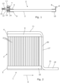
Figure 2 shows a plan view of the walkway ofFigure 1 ; -
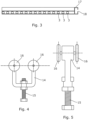
Figure 3 shows a longitudinal cross section through the walkway ofFigure 1 ; -
Figure 4 shows a side elevation of the sliding anchorage of the walkway ofFigure 1 ; and -
Figure 5 shows an end elevation of the sliding anchorage ofFigure 4 . - The accompanying drawings show a
walkway 1 that can be installed on a roof, where it is desired to reduce the likelihood of a user of the walkway falling and injuring themselves. Thewalkway 1 comprises atread 2, which comprises a plurality of metal (typically extruded aluminium)slats 3 held between a pair oftoe guards toe guards length 6 of the walkway and each engage the slats through asocket portion upstanding portion 7, 8 at the edge of thetread 2, which provides an edge to alert a user that they are approaching the edge of thewalkway 1. - For a first one of the
toe guards 4, the upstanding portion 7 is provided by atubular box section 11. This has aslot 12 therein, extending along thelength 6. Asliding anchorage 13 is provided that is held captive within thebox section 11, so that acarriage portion 14 is received within the tube, but amounting portion 15 extends out of the slot. A flexible line (not shown) can then be attached to the mounting portion 15 (of the form of a hitch or bolt or similar) in order to be attached to the user as a fall restraint or fall arrest system. - The
carriage portion 14 is U-shaped as shown inFigure 4 of the accompanying drawings and carries fourwheels 16; two above theslot 12 and two below, with a pair ofwheels 16 on each arm of the U-shape. Thus, whether the loading on the anchorage is to either side of the slot, or forwards or backwards along thelength 6, at least one of the wheels will be able to roll along the inner surface of thebox section 11. - Accordingly, the
sliding anchorage 12 can slide along thelength 6 of thefirst toe guard 4 as a user walks to and fro along thewalkway 1. The location of the sliding anchorage is provided within thefirst toe guard 4, thus providing an integrally formed walkway and fall restraint system whilst making efficient use of thefirst toe guard 4. Thus, less material is used and fewer products need to be bought in order to provide a safe walkway on a roof. Only the mountings required to mount the walkway to the roof are required; there is no need for a separate set of mountings for the fall restraint system. - It can be seen from
Figure 2 of the accompanying drawings that thefirst toe guard 4 can extend around afront side 20 of thewalkway 1 at right angles to thelength 6. Assuming that thetoe guard 4 is adequately curved, the carriage and wheels arrangement of thesliding anchorage 12 described above will have no trouble in negotiating such a curve, or the curve in the opposite direction shown in order to move ontofurther segment 19. Thus, there is no need for the user to have to unclip and reclip themselves when the walkway changes direction.
Claims (8)
- Assembly of a roof with a walkway installed on said roof, said walkway (1) comprising a tread (2) for a user to walk upon,
characterized in that the tread (2) is bounded along an elongate side by a toe guard (4, 5) having an elongate extent, said walkway (1) further comprising an anchorage (13) for a fall restraint system, in which the anchorage is a sliding anchorage (13), being able to slide along the extent of the toe guard (4 ,5) and in which the toe guard (4, 5) comprises an elongate tube (11) coupled to the tread (2), the tube (11) having a slot (12) along the length of the toe guard (4, 5) providing a location for the sliding anchorage (13). - The assembly of claim 1, in which the sliding anchorage (13) is received in the tube (11) through the slot (12), so that a captive part (14) of the sliding anchorage (13) is held captive within the tube (11), but will be able to slide within the tube (11) along the slot (12).
- The assembly of claim 2, in which the captive part (14) of the sliding anchorage (13) comprises a carriage having at least one wheel (16) depending therefrom.
- The assembly of any preceding claim in which the anchorage comprises a mounting point (15) for the fall restraint system.
- The assembly of any preceding claim, in which the anchorage (13) comprises a line running along the length of the walkway.
- The assembly of claim 5, in which the line (13) is coupled to or mounted on the toe guard (4, 5).
- A combination comprising the assembly of any preceding claim and a fall restraint system coupled to the anchorage (13).
- The combination of claim 7, in which the fall restraint system comprises a flexible line attached to the anchorage.
Applications Claiming Priority (3)
| Application Number | Priority Date | Filing Date | Title |
|---|---|---|---|
| GB1322790.5A GB2521605A (en) | 2013-12-20 | 2013-12-20 | Walkways |
| PCT/GB2014/053681 WO2015092370A1 (en) | 2013-12-20 | 2014-12-12 | Walkways |
| EP14812806.9A EP3084101B1 (en) | 2013-12-20 | 2014-12-12 | Walkways |
Related Parent Applications (2)
| Application Number | Title | Priority Date | Filing Date |
|---|---|---|---|
| EP14812806.9A Division EP3084101B1 (en) | 2013-12-20 | 2014-12-12 | Walkways |
| EP14812806.9A Division-Into EP3084101B1 (en) | 2013-12-20 | 2014-12-12 | Walkways |
Publications (3)
| Publication Number | Publication Date |
|---|---|
| EP3757314A1 EP3757314A1 (en) | 2020-12-30 |
| EP3757314B1 true EP3757314B1 (en) | 2024-09-25 |
| EP3757314C0 EP3757314C0 (en) | 2024-09-25 |
Family
ID=50071317
Family Applications (2)
| Application Number | Title | Priority Date | Filing Date |
|---|---|---|---|
| EP20186432.9A Active EP3757314B1 (en) | 2013-12-20 | 2014-12-12 | Assembly of a roof with a walkway |
| EP14812806.9A Active EP3084101B1 (en) | 2013-12-20 | 2014-12-12 | Walkways |
Family Applications After (1)
| Application Number | Title | Priority Date | Filing Date |
|---|---|---|---|
| EP14812806.9A Active EP3084101B1 (en) | 2013-12-20 | 2014-12-12 | Walkways |
Country Status (3)
| Country | Link |
|---|---|
| EP (2) | EP3757314B1 (en) |
| GB (1) | GB2521605A (en) |
| WO (1) | WO2015092370A1 (en) |
Families Citing this family (2)
| Publication number | Priority date | Publication date | Assignee | Title |
|---|---|---|---|---|
| CN112962994A (en) * | 2021-02-04 | 2021-06-15 | 中建新疆建工集团第五建筑工程有限公司 | Edge opening protection device and protection method |
| US12275496B1 (en) | 2021-06-09 | 2025-04-15 | Eric C. Meyer | Safety railing system for a hopper barge |
Family Cites Families (7)
| Publication number | Priority date | Publication date | Assignee | Title |
|---|---|---|---|---|
| FR2501267A1 (en) * | 1981-03-03 | 1982-09-10 | Entrepose | Load platform for scaffolding - comprises panels with longitudinal edges held together by co-operating fastenings |
| JPS6412855U (en) * | 1987-07-14 | 1989-01-23 | ||
| GB8918508D0 (en) * | 1989-08-14 | 1989-09-20 | West Nigel P | Apparatus for use in fitting roofing sheets |
| DE29805260U1 (en) * | 1998-03-24 | 1998-08-06 | Lück, Wilhelm, 57250 Netphen | Roof accessories |
| US6520290B1 (en) * | 2000-04-17 | 2003-02-18 | Charles L. Carter | Fall protection method and apparatus |
| GB2373537B (en) * | 2001-03-22 | 2005-09-07 | Hadrian Iye | Improved fall-arrest system for persons working at height |
| US20100012426A1 (en) * | 2008-07-15 | 2010-01-21 | Convenient Safety Systems, Inc. | Sloped Roof Safety System |
-
2013
- 2013-12-20 GB GB1322790.5A patent/GB2521605A/en not_active Withdrawn
-
2014
- 2014-12-12 WO PCT/GB2014/053681 patent/WO2015092370A1/en not_active Ceased
- 2014-12-12 EP EP20186432.9A patent/EP3757314B1/en active Active
- 2014-12-12 EP EP14812806.9A patent/EP3084101B1/en active Active
Also Published As
| Publication number | Publication date |
|---|---|
| WO2015092370A1 (en) | 2015-06-25 |
| GB201322790D0 (en) | 2014-02-05 |
| EP3084101A1 (en) | 2016-10-26 |
| GB2521605A (en) | 2015-07-01 |
| EP3757314C0 (en) | 2024-09-25 |
| EP3084101B1 (en) | 2021-01-27 |
| EP3757314A1 (en) | 2020-12-30 |
Similar Documents
| Publication | Publication Date | Title |
|---|---|---|
| EP3084101B1 (en) | Walkways | |
| CN104481131A (en) | Unidirectional ascending falling protector | |
| CN216061732U (en) | Anti-falling device for power transmission line iron tower | |
| US20140283417A1 (en) | Apparatus for remote operation on a rooftop | |
| DE102012101620A1 (en) | Isolation support for a busbar for electrically driven rail vehicles | |
| KR20140121736A (en) | Roller and Bracket Cable Protection | |
| US10806955B2 (en) | Fall arrestor to gradually absorb a pull on a safety cable coupled with the fall arrestor | |
| KR200473591Y1 (en) | Apparatus for melting frozen road using exhaust gas | |
| CN102377148A (en) | Wire cable rain-proof snow-proof device | |
| EP2662644A1 (en) | Installation assembly of photovoltaic panels | |
| CN209907196U (en) | Road and bridge rail guard | |
| CN204077535U (en) | Unmanned aerial vehicle remote sensing surveillance and monitoring mobile platform dedicated bay upper frame | |
| US20160053917A1 (en) | Conduit hanger | |
| CN105178222B (en) | Express-way guard-rail plates with wiring groove | |
| US9764659B2 (en) | Ice cap for electric cable | |
| US9933037B1 (en) | Cable dampening system and traffic control assembly comprising same | |
| CN105421751B (en) | Assembled steel pipe support stair tread and stair | |
| KR101862616B1 (en) | Apparatus for limiting offset of cable | |
| CN215057052U (en) | Adjustable foot nail anti-falling climbing system | |
| CN205544138U (en) | Prepackage type remote control de -icer | |
| CN105172557A (en) | Side guard for wheel | |
| CN103890296B (en) | Fall protection system and its application method | |
| CN209994094U (en) | Rail car slide wire cable safety arrangement | |
| CN117339135B (en) | Climbing protection devices for power towers | |
| KR101986079B1 (en) | Protection against bird access |
Legal Events
| Date | Code | Title | Description |
|---|---|---|---|
| PUAI | Public reference made under article 153(3) epc to a published international application that has entered the european phase |
Free format text: ORIGINAL CODE: 0009012 |
|
| STAA | Information on the status of an ep patent application or granted ep patent |
Free format text: STATUS: THE APPLICATION HAS BEEN PUBLISHED |
|
| AC | Divisional application: reference to earlier application |
Ref document number: 3084101 Country of ref document: EP Kind code of ref document: P |
|
| AK | Designated contracting states |
Kind code of ref document: A1 Designated state(s): AL AT BE BG CH CY CZ DE DK EE ES FI FR GB GR HR HU IE IS IT LI LT LU LV MC MK MT NL NO PL PT RO RS SE SI SK SM TR |
|
| STAA | Information on the status of an ep patent application or granted ep patent |
Free format text: STATUS: REQUEST FOR EXAMINATION WAS MADE |
|
| 17P | Request for examination filed |
Effective date: 20210630 |
|
| RBV | Designated contracting states (corrected) |
Designated state(s): AL AT BE BG CH CY CZ DE DK EE ES FI FR GB GR HR HU IE IS IT LI LT LU LV MC MK MT NL NO PL PT RO RS SE SI SK SM TR |
|
| GRAP | Despatch of communication of intention to grant a patent |
Free format text: ORIGINAL CODE: EPIDOSNIGR1 |
|
| STAA | Information on the status of an ep patent application or granted ep patent |
Free format text: STATUS: GRANT OF PATENT IS INTENDED |
|
| RIC1 | Information provided on ipc code assigned before grant |
Ipc: E04G 7/28 20060101ALN20240404BHEP Ipc: E04G 3/22 20060101ALI20240404BHEP Ipc: E04G 5/14 20060101ALI20240404BHEP Ipc: E04D 13/12 20060101ALI20240404BHEP Ipc: E04G 21/32 20060101ALI20240404BHEP Ipc: A62B 35/00 20060101ALI20240404BHEP Ipc: E04G 5/00 20060101AFI20240404BHEP |
|
| INTG | Intention to grant announced |
Effective date: 20240418 |
|
| GRAS | Grant fee paid |
Free format text: ORIGINAL CODE: EPIDOSNIGR3 |
|
| GRAA | (expected) grant |
Free format text: ORIGINAL CODE: 0009210 |
|
| STAA | Information on the status of an ep patent application or granted ep patent |
Free format text: STATUS: THE PATENT HAS BEEN GRANTED |
|
| AC | Divisional application: reference to earlier application |
Ref document number: 3084101 Country of ref document: EP Kind code of ref document: P |
|
| AK | Designated contracting states |
Kind code of ref document: B1 Designated state(s): AL AT BE BG CH CY CZ DE DK EE ES FI FR GB GR HR HU IE IS IT LI LT LU LV MC MK MT NL NO PL PT RO RS SE SI SK SM TR |
|
| REG | Reference to a national code |
Ref country code: GB Ref legal event code: FG4D |
|
| RIN1 | Information on inventor provided before grant (corrected) |
Inventor name: EVANS, JOHN P. |
|
| REG | Reference to a national code |
Ref country code: CH Ref legal event code: EP |
|
| REG | Reference to a national code |
Ref country code: DE Ref legal event code: R096 Ref document number: 602014090935 Country of ref document: DE |
|
| REG | Reference to a national code |
Ref country code: IE Ref legal event code: FG4D |
|
| U01 | Request for unitary effect filed |
Effective date: 20240925 |
|
| U07 | Unitary effect registered |
Designated state(s): AT BE BG DE DK EE FI FR IT LT LU LV MT NL PT RO SE SI Effective date: 20241008 |
|
| U20 | Renewal fee for the european patent with unitary effect paid |
Year of fee payment: 11 Effective date: 20241029 |
|
| PG25 | Lapsed in a contracting state [announced via postgrant information from national office to epo] |
Ref country code: NO Free format text: LAPSE BECAUSE OF FAILURE TO SUBMIT A TRANSLATION OF THE DESCRIPTION OR TO PAY THE FEE WITHIN THE PRESCRIBED TIME-LIMIT Effective date: 20241225 |
|
| PG25 | Lapsed in a contracting state [announced via postgrant information from national office to epo] |
Ref country code: GR Free format text: LAPSE BECAUSE OF FAILURE TO SUBMIT A TRANSLATION OF THE DESCRIPTION OR TO PAY THE FEE WITHIN THE PRESCRIBED TIME-LIMIT Effective date: 20241226 |
|
| PG25 | Lapsed in a contracting state [announced via postgrant information from national office to epo] |
Ref country code: RS Free format text: LAPSE BECAUSE OF FAILURE TO SUBMIT A TRANSLATION OF THE DESCRIPTION OR TO PAY THE FEE WITHIN THE PRESCRIBED TIME-LIMIT Effective date: 20241225 |
|
| PG25 | Lapsed in a contracting state [announced via postgrant information from national office to epo] |
Ref country code: RS Free format text: LAPSE BECAUSE OF FAILURE TO SUBMIT A TRANSLATION OF THE DESCRIPTION OR TO PAY THE FEE WITHIN THE PRESCRIBED TIME-LIMIT Effective date: 20241225 Ref country code: NO Free format text: LAPSE BECAUSE OF FAILURE TO SUBMIT A TRANSLATION OF THE DESCRIPTION OR TO PAY THE FEE WITHIN THE PRESCRIBED TIME-LIMIT Effective date: 20241225 Ref country code: GR Free format text: LAPSE BECAUSE OF FAILURE TO SUBMIT A TRANSLATION OF THE DESCRIPTION OR TO PAY THE FEE WITHIN THE PRESCRIBED TIME-LIMIT Effective date: 20241226 |
|
| PG25 | Lapsed in a contracting state [announced via postgrant information from national office to epo] |
Ref country code: IS Free format text: LAPSE BECAUSE OF FAILURE TO SUBMIT A TRANSLATION OF THE DESCRIPTION OR TO PAY THE FEE WITHIN THE PRESCRIBED TIME-LIMIT Effective date: 20250125 |
|
| PG25 | Lapsed in a contracting state [announced via postgrant information from national office to epo] |
Ref country code: SM Free format text: LAPSE BECAUSE OF FAILURE TO SUBMIT A TRANSLATION OF THE DESCRIPTION OR TO PAY THE FEE WITHIN THE PRESCRIBED TIME-LIMIT Effective date: 20240925 |
|
| PG25 | Lapsed in a contracting state [announced via postgrant information from national office to epo] |
Ref country code: ES Free format text: LAPSE BECAUSE OF FAILURE TO SUBMIT A TRANSLATION OF THE DESCRIPTION OR TO PAY THE FEE WITHIN THE PRESCRIBED TIME-LIMIT Effective date: 20240925 |
|
| PG25 | Lapsed in a contracting state [announced via postgrant information from national office to epo] |
Ref country code: PL Free format text: LAPSE BECAUSE OF FAILURE TO SUBMIT A TRANSLATION OF THE DESCRIPTION OR TO PAY THE FEE WITHIN THE PRESCRIBED TIME-LIMIT Effective date: 20240925 Ref country code: CZ Free format text: LAPSE BECAUSE OF FAILURE TO SUBMIT A TRANSLATION OF THE DESCRIPTION OR TO PAY THE FEE WITHIN THE PRESCRIBED TIME-LIMIT Effective date: 20240925 |
|
| PG25 | Lapsed in a contracting state [announced via postgrant information from national office to epo] |
Ref country code: SK Free format text: LAPSE BECAUSE OF FAILURE TO SUBMIT A TRANSLATION OF THE DESCRIPTION OR TO PAY THE FEE WITHIN THE PRESCRIBED TIME-LIMIT Effective date: 20240925 |
|
| PG25 | Lapsed in a contracting state [announced via postgrant information from national office to epo] |
Ref country code: MC Free format text: LAPSE BECAUSE OF FAILURE TO SUBMIT A TRANSLATION OF THE DESCRIPTION OR TO PAY THE FEE WITHIN THE PRESCRIBED TIME-LIMIT Effective date: 20240925 |
|
| REG | Reference to a national code |
Ref country code: CH Ref legal event code: PL |
|
| PLBE | No opposition filed within time limit |
Free format text: ORIGINAL CODE: 0009261 |
|
| STAA | Information on the status of an ep patent application or granted ep patent |
Free format text: STATUS: NO OPPOSITION FILED WITHIN TIME LIMIT |
|
| 26N | No opposition filed |
Effective date: 20250626 |
|
| PG25 | Lapsed in a contracting state [announced via postgrant information from national office to epo] |
Ref country code: CH Free format text: LAPSE BECAUSE OF NON-PAYMENT OF DUE FEES Effective date: 20241231 |
|
| PG25 | Lapsed in a contracting state [announced via postgrant information from national office to epo] |
Ref country code: IE Free format text: LAPSE BECAUSE OF NON-PAYMENT OF DUE FEES Effective date: 20241212 |
|
| U20 | Renewal fee for the european patent with unitary effect paid |
Year of fee payment: 12 Effective date: 20251029 |
|
| PGFP | Annual fee paid to national office [announced via postgrant information from national office to epo] |
Ref country code: GB Payment date: 20251028 Year of fee payment: 12 |
|
| PG25 | Lapsed in a contracting state [announced via postgrant information from national office to epo] |
Ref country code: HR Free format text: LAPSE BECAUSE OF FAILURE TO SUBMIT A TRANSLATION OF THE DESCRIPTION OR TO PAY THE FEE WITHIN THE PRESCRIBED TIME-LIMIT Effective date: 20240925 |