EP3757058A1 - An electric lifting truck - Google Patents
An electric lifting truck Download PDFInfo
- Publication number
- EP3757058A1 EP3757058A1 EP20178733.0A EP20178733A EP3757058A1 EP 3757058 A1 EP3757058 A1 EP 3757058A1 EP 20178733 A EP20178733 A EP 20178733A EP 3757058 A1 EP3757058 A1 EP 3757058A1
- Authority
- EP
- European Patent Office
- Prior art keywords
- lifting truck
- wheels
- truck according
- lifting
- electric motor
- Prior art date
- Legal status (The legal status is an assumption and is not a legal conclusion. Google has not performed a legal analysis and makes no representation as to the accuracy of the status listed.)
- Granted
Links
- 239000003638 chemical reducing agent Substances 0.000 claims 1
- 230000005540 biological transmission Effects 0.000 description 2
- 238000005457 optimization Methods 0.000 description 2
- 230000015572 biosynthetic process Effects 0.000 description 1
- 238000010276 construction Methods 0.000 description 1
- 230000002452 interceptive effect Effects 0.000 description 1
- 238000004519 manufacturing process Methods 0.000 description 1
- 230000009347 mechanical transmission Effects 0.000 description 1
- 239000002184 metal Substances 0.000 description 1
Images


Classifications
-
- B—PERFORMING OPERATIONS; TRANSPORTING
- B66—HOISTING; LIFTING; HAULING
- B66F—HOISTING, LIFTING, HAULING OR PUSHING, NOT OTHERWISE PROVIDED FOR, e.g. DEVICES WHICH APPLY A LIFTING OR PUSHING FORCE DIRECTLY TO THE SURFACE OF A LOAD
- B66F9/00—Devices for lifting or lowering bulky or heavy goods for loading or unloading purposes
- B66F9/06—Devices for lifting or lowering bulky or heavy goods for loading or unloading purposes movable, with their loads, on wheels or the like, e.g. fork-lift trucks
- B66F9/075—Constructional features or details
- B66F9/07513—Details concerning the chassis
- B66F9/07531—Battery compartments
-
- B—PERFORMING OPERATIONS; TRANSPORTING
- B60—VEHICLES IN GENERAL
- B60K—ARRANGEMENT OR MOUNTING OF PROPULSION UNITS OR OF TRANSMISSIONS IN VEHICLES; ARRANGEMENT OR MOUNTING OF PLURAL DIVERSE PRIME-MOVERS IN VEHICLES; AUXILIARY DRIVES FOR VEHICLES; INSTRUMENTATION OR DASHBOARDS FOR VEHICLES; ARRANGEMENTS IN CONNECTION WITH COOLING, AIR INTAKE, GAS EXHAUST OR FUEL SUPPLY OF PROPULSION UNITS IN VEHICLES
- B60K1/00—Arrangement or mounting of electrical propulsion units
-
- B—PERFORMING OPERATIONS; TRANSPORTING
- B66—HOISTING; LIFTING; HAULING
- B66F—HOISTING, LIFTING, HAULING OR PUSHING, NOT OTHERWISE PROVIDED FOR, e.g. DEVICES WHICH APPLY A LIFTING OR PUSHING FORCE DIRECTLY TO THE SURFACE OF A LOAD
- B66F9/00—Devices for lifting or lowering bulky or heavy goods for loading or unloading purposes
- B66F9/06—Devices for lifting or lowering bulky or heavy goods for loading or unloading purposes movable, with their loads, on wheels or the like, e.g. fork-lift trucks
- B66F9/065—Devices for lifting or lowering bulky or heavy goods for loading or unloading purposes movable, with their loads, on wheels or the like, e.g. fork-lift trucks non-masted
- B66F9/0655—Devices for lifting or lowering bulky or heavy goods for loading or unloading purposes movable, with their loads, on wheels or the like, e.g. fork-lift trucks non-masted with a telescopic boom
-
- B—PERFORMING OPERATIONS; TRANSPORTING
- B66—HOISTING; LIFTING; HAULING
- B66F—HOISTING, LIFTING, HAULING OR PUSHING, NOT OTHERWISE PROVIDED FOR, e.g. DEVICES WHICH APPLY A LIFTING OR PUSHING FORCE DIRECTLY TO THE SURFACE OF A LOAD
- B66F9/00—Devices for lifting or lowering bulky or heavy goods for loading or unloading purposes
- B66F9/06—Devices for lifting or lowering bulky or heavy goods for loading or unloading purposes movable, with their loads, on wheels or the like, e.g. fork-lift trucks
- B66F9/075—Constructional features or details
- B66F9/07568—Steering arrangements
-
- B—PERFORMING OPERATIONS; TRANSPORTING
- B66—HOISTING; LIFTING; HAULING
- B66F—HOISTING, LIFTING, HAULING OR PUSHING, NOT OTHERWISE PROVIDED FOR, e.g. DEVICES WHICH APPLY A LIFTING OR PUSHING FORCE DIRECTLY TO THE SURFACE OF A LOAD
- B66F9/00—Devices for lifting or lowering bulky or heavy goods for loading or unloading purposes
- B66F9/06—Devices for lifting or lowering bulky or heavy goods for loading or unloading purposes movable, with their loads, on wheels or the like, e.g. fork-lift trucks
- B66F9/075—Constructional features or details
- B66F9/07572—Propulsion arrangements
-
- B—PERFORMING OPERATIONS; TRANSPORTING
- B66—HOISTING; LIFTING; HAULING
- B66F—HOISTING, LIFTING, HAULING OR PUSHING, NOT OTHERWISE PROVIDED FOR, e.g. DEVICES WHICH APPLY A LIFTING OR PUSHING FORCE DIRECTLY TO THE SURFACE OF A LOAD
- B66F9/00—Devices for lifting or lowering bulky or heavy goods for loading or unloading purposes
- B66F9/06—Devices for lifting or lowering bulky or heavy goods for loading or unloading purposes movable, with their loads, on wheels or the like, e.g. fork-lift trucks
- B66F9/075—Constructional features or details
- B66F9/07586—Suspension or mounting of wheels on chassis
-
- B—PERFORMING OPERATIONS; TRANSPORTING
- B60—VEHICLES IN GENERAL
- B60K—ARRANGEMENT OR MOUNTING OF PROPULSION UNITS OR OF TRANSMISSIONS IN VEHICLES; ARRANGEMENT OR MOUNTING OF PLURAL DIVERSE PRIME-MOVERS IN VEHICLES; AUXILIARY DRIVES FOR VEHICLES; INSTRUMENTATION OR DASHBOARDS FOR VEHICLES; ARRANGEMENTS IN CONNECTION WITH COOLING, AIR INTAKE, GAS EXHAUST OR FUEL SUPPLY OF PROPULSION UNITS IN VEHICLES
- B60K1/00—Arrangement or mounting of electrical propulsion units
- B60K2001/001—Arrangement or mounting of electrical propulsion units one motor mounted on a propulsion axle for rotating right and left wheels of this axle
-
- B—PERFORMING OPERATIONS; TRANSPORTING
- B60—VEHICLES IN GENERAL
- B60Y—INDEXING SCHEME RELATING TO ASPECTS CROSS-CUTTING VEHICLE TECHNOLOGY
- B60Y2200/00—Type of vehicle
- B60Y2200/10—Road Vehicles
- B60Y2200/15—Fork lift trucks, Industrial trucks
Definitions
- the present invention relates to an electric lifting truck.
- Electric lifting trucks must generally have very small turning radii in order to be able to maneuver in confined spaces, for example, in the aisles of industrial or commercial warehouses.
- Electric lifting trucks have recently been proposed with a pivoting rear axle carrying two steered rear wheels driven by an electric motor.
- the electric motor for driving the rear wheels is positioned away from the rear axle and is connected to the rear axle by a mechanical transmission including a cardan shaft.
- This solution has the drawback of reducing the energy efficiency of the machine due to the use of a cardan shaft.
- this solution involves a large footprint in the central area of the machine, which hinders the positioning of the battery pack.
- Solutions have also been proposed which envisage installing the electric motor directly on the rear axle.
- the solutions typically adopted allow reduced steering angles to be obtained (generally not higher than 55°) due to the need for avoiding interference between the wheels and the motor in the steered configuration of the wheels.
- rear wheels with a smaller diameter than the diameter of the front wheels are usually used in order to increase the maximum steering angle without causing interference between the wheels and the motor.
- the object of the present invention is to provide an electrically-operated lifting truck that overcomes the problems of the prior art.
- the present invention aims to provide an electric lifting truck having minimum turning radii, usable on rough terrain and which allows maximization of energy efficiency.
- this object is achieved by an electric lifting truck having the characteristics forming the subject of claim 1.
- Embodiments of the present invention relate to an electric lifting truck wherein the steered rear wheels are carried by a rear axle hinged to the frame and pivoting around a longitudinal axis, and provided with a rear electric traction motor mounted directly on the rear axle and wherein the rotation axis of the electric motor is oriented in the vertical direction.
- This arrangement prevents the rear wheels from interfering with the overall footprint of the rear electric motor with the maximum steering angle. In this way it is possible to reach high steering angles of the rear wheels, for example greater than 55°.
- This arrangement of the rear electric motor offers greater freedom in the design of the steering device of the rear wheels.
- the area of the lifting truck between the rear axle and the front wheels is completely free from mechanical components, so that it is possible to obtain a large compartment between the rear axle and the front wheels for the battery pack.
- the battery pack can, therefore, be removed from one side of the lifting truck without the need to divide it into two or more parts.
- the present invention therefore allows production of an electric lifting truck with electric four-wheel drive and with a pivoting rear axle and with rear steered wheels with a large diameter and a high steering angle. This arrangement allows the use of the lifting truck on rough terrain, for example in agricultural environments.
- the rear wheels may have the same diameter as the front wheels and may have a diameter equal to or greater than half the width of the lifting truck.
- numeral 10 indicates an electric lifting truck according to an embodiment of the present invention.
- the lifting truck 10 comprises a frame 12 which carries a pair of front drive wheels 14 and a pair of rear drive and steered wheels 16.
- the vehicle 10 comprises a driving cab 18, a battery pack 20 and a lifting device 22.
- the lifting device 22 comprises a telescopic arm 24 articulated in a rear section 26 of the frame 12 around a transverse axis B.
- the telescopic arm 24 carries an attachment 28 at its distal end for an implement 30, formed for example by a fork.
- the driving cab 18 is located laterally with respect to the telescopic arm 24 and the battery pack 20 is housed in a compartment 32 of the frame 12 accessible on a side of the lifting truck 10 opposite the driving cab 18.
- the lifting truck 10 instead of the telescopic arm 24 could be equipped with a gantry lifting device mounted on the front part of the frame 12.
- the driving cab could be mounted centrally behind the gantry lifting device.
- the front wheels 14 are non-steered drive wheels, driven by respective front electric motors 34 fixed to the frame 12 and arranged with the respective rotation axes oriented transversely and aligned with each other.
- Each front electric motor 34 can be connected to the respective wheel 14 by means of a gearbox 36.
- the lifting truck 10 comprises a rear axle 38 which carries the rear wheels 16.
- the rear wheels 16 are driving and steered.
- the rear axle 38 is mounted on the frame 12 pivoting around a longitudinal axis A of the lifting truck 10.
- the pivoting assembly of the rear axle 38 on the frame 12 can be carried out by means of a pair of brackets 40 fixed to the frame 12 and engaged by longitudinal pins aligned with each other, fixed with respect to the rear axle 38.
- the rear axle 38 can be formed of a hollow metal body in which a rear transmission is housed including a differential gear 42 and two axle shafts 44.
- the rear wheels 16 are connected to the respective axle shafts 44 by means of homokinetic joints 46.
- the rear wheels 16 can be connected to the respective homokinetic joints 46 by means of respective gearboxes 48 which can be, for example, planetary gearboxes.
- the lifting truck 10 comprises a rear electric motor 50 which is fixed to the rear axle by means of a support 52.
- the electric motor 50 has a vertically oriented rotation axis C.
- the rotation axis C can be perpendicular to the longitudinal axis A of the lifting truck 10.
- the lifting truck 10 comprises a steering device 54 for controlling the steering of the rear wheels 16.
- the steering device 54 comprises a steering actuator 56, which can be fixed to the rear axle 38, and two steering tie rods 58 articulated to respective steering levers 60, which control the steering of the respective rear wheels 16.
- the rear wheels 16 can have the same diameter as the front wheels 14. In a possible embodiment, the rear wheels 16 can have a diameter equal to or greater than half the width of the lifting truck 10.
- the rear axle 38 is illustrated in a plan view in the configuration of maximum steering angle.
- the steering device has not been shown to simplify the representation.
- the vertical arrangement of the motor 50 allows very high steering angles of the rear wheels 16 (for example, greater than 55°) without there being any risk of interference between the rear wheels 16 and the rear motor 50, even in the case where the rear wheels 16 have a large diameter.
- the vertical arrangement of the rear electric motor 50 also allows greater freedom in the design of the steering device of the rear wheels.
- this arrangement of the rear electric motor 50 allows connection of the electric motor 50 to the rear differential gear 52 without the need for a cardan shaft, which allows optimization of the energy efficiency of the transmission.
- a further advantage of the solution according to the invention is that the central part of the frame 12 between the rear axle 38 and the front wheels 14 is free from mechanical components and allows formation of a large battery compartment 32. This - in turn - allows the provision of a single battery pack 20, without the need to divide the battery pack into two or more parts.
- the battery pack 20 is easily accessible on the side of the lifting truck 10 and can be inserted and extracted laterally by means of a forklift truck.
Landscapes
- Engineering & Computer Science (AREA)
- Transportation (AREA)
- Structural Engineering (AREA)
- Mechanical Engineering (AREA)
- Civil Engineering (AREA)
- Life Sciences & Earth Sciences (AREA)
- Geology (AREA)
- Chemical & Material Sciences (AREA)
- Combustion & Propulsion (AREA)
- Forklifts And Lifting Vehicles (AREA)
- Conductive Materials (AREA)
- Inorganic Insulating Materials (AREA)
Abstract
Description
- The present invention relates to an electric lifting truck.
- Electric lifting trucks must generally have very small turning radii in order to be able to maneuver in confined spaces, for example, in the aisles of industrial or commercial warehouses.
- To reduce the turning radii, some known electric lifting trucks are equipped with a single steered rear wheel or a pair of twin wheels. This solution allows very high steering angles to be obtained. However, in this case, the single rear wheel or the twin rear wheels are generally idle and traction is entrusted to the front wheels only. An example of this solution is illustrated, for example, in
EP-A-0569277 , which describes an electric forklift truck including a frame, two front wheels and at least one rear wheel, a driver's cab, a battery compartment, and a telescopic lifting arm articulated in the rear part of the frame and extending forwards along a median longitudinal axis of the truck. - There are also lifting trucks with rear wheel drive, with a single motorized rear wheel or with motorized twin rear wheels. Solutions with a single rear wheel or with twin rear wheels, both idle and motorized, offer the advantage of a reduced turning radius but are generally not suitable for use on uneven terrain.
- Electric lifting trucks have recently been proposed with a pivoting rear axle carrying two steered rear wheels driven by an electric motor.
- To increase the steering angles in solutions with a pivoting rear axle and rear drive wheels, the electric motor for driving the rear wheels is positioned away from the rear axle and is connected to the rear axle by a mechanical transmission including a cardan shaft. This solution has the drawback of reducing the energy efficiency of the machine due to the use of a cardan shaft. Furthermore, this solution involves a large footprint in the central area of the machine, which hinders the positioning of the battery pack.
- Solutions have also been proposed which envisage installing the electric motor directly on the rear axle. However, the solutions typically adopted allow reduced steering angles to be obtained (generally not higher than 55°) due to the need for avoiding interference between the wheels and the motor in the steered configuration of the wheels. To increase the turning radius in lifting trucks with steered motorized rear axle, rear wheels with a smaller diameter than the diameter of the front wheels are usually used in order to increase the maximum steering angle without causing interference between the wheels and the motor.
- In the current state of the art, there are no solutions that allow the obtainment of small turning radii, the use on rough terrain, and the optimization of energy efficiency.
- The object of the present invention is to provide an electrically-operated lifting truck that overcomes the problems of the prior art.
- In particular, the present invention aims to provide an electric lifting truck having minimum turning radii, usable on rough terrain and which allows maximization of energy efficiency.
- According to the present invention, this object is achieved by an electric lifting truck having the characteristics forming the subject of claim 1.
- Embodiments of the present invention relate to an electric lifting truck wherein the steered rear wheels are carried by a rear axle hinged to the frame and pivoting around a longitudinal axis, and provided with a rear electric traction motor mounted directly on the rear axle and wherein the rotation axis of the electric motor is oriented in the vertical direction.
- This arrangement prevents the rear wheels from interfering with the overall footprint of the rear electric motor with the maximum steering angle. In this way it is possible to reach high steering angles of the rear wheels, for example greater than 55°.
- This arrangement of the rear electric motor offers greater freedom in the design of the steering device of the rear wheels.
- Furthermore, with this arrangement of the rear electric motor, the area of the lifting truck between the rear axle and the front wheels is completely free from mechanical components, so that it is possible to obtain a large compartment between the rear axle and the front wheels for the battery pack. The battery pack can, therefore, be removed from one side of the lifting truck without the need to divide it into two or more parts.
- The present invention therefore allows production of an electric lifting truck with electric four-wheel drive and with a pivoting rear axle and with rear steered wheels with a large diameter and a high steering angle. This arrangement allows the use of the lifting truck on rough terrain, for example in agricultural environments.
- According to a possible embodiment of the invention, the rear wheels may have the same diameter as the front wheels and may have a diameter equal to or greater than half the width of the lifting truck.
- Further characteristics and advantages of the invention will become apparent from the detailed description that follows, given purely by way of nonlimiting example, wherein:
-
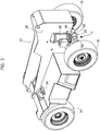
Figure 1 is a perspective view of a possible embodiment of an electric lifting truck according to the present invention, -
Figures 2 and3 are perspective views from different angles of the lifting truck ofFigure 1 with the driving cab and telescopic arm removed, -
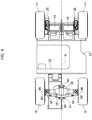
Figure 4 is a plan view from below of the lifting truck ofFigure 1 , -
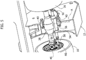
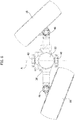
Figure 5 is a perspective view of the part indicated by the arrow V inFigure 3 . -
Figure 6 is an exploded perspective view of the rear axle of the lifting truck according to the invention, -
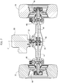
Figure 7 is a vertical cross-section of the rear axle of the lifting truck according to the invention, and -
Figure 8 is a plan view of the rear axle in a steered configuration. - With reference to
Figure 1 ,numeral 10 indicates an electric lifting truck according to an embodiment of the present invention. Thelifting truck 10 comprises aframe 12 which carries a pair offront drive wheels 14 and a pair of rear drive and steeredwheels 16. - The
vehicle 10 comprises adriving cab 18, abattery pack 20 and alifting device 22. In the embodiment illustrated in the figures, thelifting device 22 comprises atelescopic arm 24 articulated in arear section 26 of theframe 12 around a transverse axis B. Thetelescopic arm 24 carries anattachment 28 at its distal end for animplement 30, formed for example by a fork. - In the illustrated embodiment, the
driving cab 18 is located laterally with respect to thetelescopic arm 24 and thebattery pack 20 is housed in acompartment 32 of theframe 12 accessible on a side of thelifting truck 10 opposite thedriving cab 18. - In a possible embodiment, the
lifting truck 10 instead of thetelescopic arm 24 could be equipped with a gantry lifting device mounted on the front part of theframe 12. In this case, the driving cab could be mounted centrally behind the gantry lifting device. - With reference to
Figures 2 ,3 and4 , thefront wheels 14 are non-steered drive wheels, driven by respective frontelectric motors 34 fixed to theframe 12 and arranged with the respective rotation axes oriented transversely and aligned with each other. Each frontelectric motor 34 can be connected to therespective wheel 14 by means of agearbox 36. - With reference to
Figures 3 ,4 and5 , thelifting truck 10 comprises arear axle 38 which carries therear wheels 16. Therear wheels 16 are driving and steered. Therear axle 38 is mounted on theframe 12 pivoting around a longitudinal axis A of thelifting truck 10. - With particular reference to
Figures 5 and6 , the pivoting assembly of therear axle 38 on theframe 12 can be carried out by means of a pair ofbrackets 40 fixed to theframe 12 and engaged by longitudinal pins aligned with each other, fixed with respect to therear axle 38. - With reference to
Figures 6 and7 , therear axle 38 can be formed of a hollow metal body in which a rear transmission is housed including adifferential gear 42 and twoaxle shafts 44. Therear wheels 16 are connected to therespective axle shafts 44 by means ofhomokinetic joints 46. In a possible embodiment, therear wheels 16 can be connected to the respectivehomokinetic joints 46 by means ofrespective gearboxes 48 which can be, for example, planetary gearboxes. - The
lifting truck 10 comprises a rearelectric motor 50 which is fixed to the rear axle by means of asupport 52. Theelectric motor 50 has a vertically oriented rotation axis C. The rotation axis C can be perpendicular to the longitudinal axis A of thelifting truck 10. - With reference to
Figures 4 ,5 and6 , thelifting truck 10 comprises asteering device 54 for controlling the steering of therear wheels 16. Thesteering device 54 comprises asteering actuator 56, which can be fixed to therear axle 38, and twosteering tie rods 58 articulated torespective steering levers 60, which control the steering of the respectiverear wheels 16. - In a possible embodiment of the present invention, the
rear wheels 16 can have the same diameter as thefront wheels 14. In a possible embodiment, therear wheels 16 can have a diameter equal to or greater than half the width of thelifting truck 10. - In
Figure 8 , therear axle 38 is illustrated in a plan view in the configuration of maximum steering angle. In this figure the steering device has not been shown to simplify the representation. With reference toFigure 8 , it can be appreciated that the vertical arrangement of themotor 50 allows very high steering angles of the rear wheels 16 (for example, greater than 55°) without there being any risk of interference between therear wheels 16 and therear motor 50, even in the case where therear wheels 16 have a large diameter. - Therefore, thanks to this arrangement, it is possible to produce a lifting truck with a pivoting rear axle having drive and steered rear wheels, and wherein the rear wheels can have a large diameter, which makes it possible to use the lifting truck even on uneven or rough terrain.
- The vertical arrangement of the rear
electric motor 50 also allows greater freedom in the design of the steering device of the rear wheels. - Furthermore, this arrangement of the rear
electric motor 50 allows connection of theelectric motor 50 to the reardifferential gear 52 without the need for a cardan shaft, which allows optimization of the energy efficiency of the transmission. - A further advantage of the solution according to the invention is that the central part of the
frame 12 between therear axle 38 and thefront wheels 14 is free from mechanical components and allows formation of alarge battery compartment 32. This - in turn - allows the provision of asingle battery pack 20, without the need to divide the battery pack into two or more parts. Thebattery pack 20 is easily accessible on the side of the liftingtruck 10 and can be inserted and extracted laterally by means of a forklift truck. - Of course, without prejudice to the principle of the invention, the details of construction and the embodiments can be widely varied with respect to those described and illustrated, without thereby departing from the scope of the invention as defined by the claims that follow.
Claims (11)
- An electric lifting truck, comprising a frame (12) carrying a pair of front drive wheels (14) and a rear axle (38) carrying a pair of rear steered drive wheels (16) driven by a rear electric motor (50), characterized in that the rear electric motor (50) is fixed to the rear axle (38) and is arranged with its own rotation axis (C) oriented vertically.
- A lifting truck according to claim 1, characterized in that the rotation axis (C) of the rear electric motor (50) is orthogonal to the longitudinal axis (A) of the lifting truck (10).
- A lifting truck according to claim 1 or claim 2, characterized in that the rear electric motor (50) is fixed to the rear axle (38) by means of a support (52) .
- A lifting truck according to any one of the preceding claims, characterized in that the rear electric motor (50) is connected to a differential gear (42) housed inside the rear axle (38) and connected to the rear wheels (16) by means of a pair of drive shafts (44) .
- A lifting truck according to claim 4, characterized in that said drive shafts (44) are connected to the respective rear wheels (16) by means of respective homokinetic joints (46) and through respective speed reducers (48).
- A lifting truck according to any one of the preceding claims, characterized in that the rear wheels (16) have the same diameter as the front wheels (14).
- A lifting truck according to any one of the preceding claims, characterized in that the rear wheels (16) have a diameter equal to or greater than half the width of the lifting truck (10).
- A lifting truck according to any one of the preceding claims, characterized in that it comprises a steering device (54) comprising a steering actuator (56) fixed to the rear axle (38) and connected by means of a pair of steering rods (58) to steering arms (60) of the respective rear wheels (16).
- A lifting truck according to any one of the preceding claims, characterized in that it comprises a lifting device (22) including a telescopic arm (24) articulated to a rear section (26) of the frame (12) about a transverse axis (B) and extending forwards.
- A lifting truck according to any one of the preceding claims, characterized in that it comprises a gantry lifting device mounted on the front part of the frame (12).
- A lifting truck according to any one of the preceding claims, characterized in that it comprises a side driving cab (18) and a battery compartment (32) containing a battery pack (20) which can be pulled out laterally from the side of the frame (12) opposite to said driving cab (18).
Applications Claiming Priority (1)
| Application Number | Priority Date | Filing Date | Title |
|---|---|---|---|
| IT102019000010098A IT201900010098A1 (en) | 2019-06-26 | 2019-06-26 | ELECTRIC FORKLIFT |
Publications (2)
| Publication Number | Publication Date |
|---|---|
| EP3757058A1 true EP3757058A1 (en) | 2020-12-30 |
| EP3757058B1 EP3757058B1 (en) | 2024-02-14 |
Family
ID=68426623
Family Applications (1)
| Application Number | Title | Priority Date | Filing Date |
|---|---|---|---|
| EP20178733.0A Active EP3757058B1 (en) | 2019-06-26 | 2020-06-08 | An electric lifting truck |
Country Status (2)
| Country | Link |
|---|---|
| EP (1) | EP3757058B1 (en) |
| IT (1) | IT201900010098A1 (en) |
Families Citing this family (1)
| Publication number | Priority date | Publication date | Assignee | Title |
|---|---|---|---|---|
| GB2623565A (en) * | 2022-10-20 | 2024-04-24 | Bamford Excavators Ltd | A material handling machine |
Citations (6)
| Publication number | Priority date | Publication date | Assignee | Title |
|---|---|---|---|---|
| EP0569277A1 (en) | 1992-05-07 | 1993-11-10 | Manitou Bf | Electric lifting vehicle with a telescopic boom |
| CN203580592U (en) * | 2013-11-01 | 2014-05-07 | 崔胜民 | Second-gear transaxle assembly of electric vehicle |
| US20150107914A1 (en) * | 2013-10-23 | 2015-04-23 | Dezhou David Zhao | All Electric / Electrical Vehicles |
| CN205930205U (en) * | 2016-08-29 | 2017-02-08 | 无锡晶华汽车零部件有限公司 | Upright motor rear axle |
| WO2019040028A2 (en) * | 2017-06-02 | 2019-02-28 | Moduler Makina Sanayi Ve Ticaret Anonim Sirketi | Machine configuration system capable of different works by means of various components and equipments |
| US20190128316A1 (en) * | 2017-10-26 | 2019-05-02 | Honda Motor Co., Ltd. | Rotor unit and rotor unit manufacturing method |
-
2019
- 2019-06-26 IT IT102019000010098A patent/IT201900010098A1/en unknown
-
2020
- 2020-06-08 EP EP20178733.0A patent/EP3757058B1/en active Active
Patent Citations (6)
| Publication number | Priority date | Publication date | Assignee | Title |
|---|---|---|---|---|
| EP0569277A1 (en) | 1992-05-07 | 1993-11-10 | Manitou Bf | Electric lifting vehicle with a telescopic boom |
| US20150107914A1 (en) * | 2013-10-23 | 2015-04-23 | Dezhou David Zhao | All Electric / Electrical Vehicles |
| CN203580592U (en) * | 2013-11-01 | 2014-05-07 | 崔胜民 | Second-gear transaxle assembly of electric vehicle |
| CN205930205U (en) * | 2016-08-29 | 2017-02-08 | 无锡晶华汽车零部件有限公司 | Upright motor rear axle |
| WO2019040028A2 (en) * | 2017-06-02 | 2019-02-28 | Moduler Makina Sanayi Ve Ticaret Anonim Sirketi | Machine configuration system capable of different works by means of various components and equipments |
| US20190128316A1 (en) * | 2017-10-26 | 2019-05-02 | Honda Motor Co., Ltd. | Rotor unit and rotor unit manufacturing method |
Also Published As
| Publication number | Publication date |
|---|---|
| IT201900010098A1 (en) | 2020-12-26 |
| EP3757058B1 (en) | 2024-02-14 |
Similar Documents
| Publication | Publication Date | Title |
|---|---|---|
| EP2064107B1 (en) | Four wheel drive system | |
| EP3263371B1 (en) | Axle device | |
| DE10343640B4 (en) | Steering system for an agricultural or industrial utility vehicle | |
| EP2628660A1 (en) | Steering apparatus for a tractor | |
| JP5722577B2 (en) | Wheeled work vehicle | |
| EP3757058A1 (en) | An electric lifting truck | |
| KR101324013B1 (en) | Electric drive type agriculture vehicles | |
| WO2005101945A3 (en) | Off road vehicle steering systems | |
| US8978810B2 (en) | Tractor | |
| EP3093216A1 (en) | A steering system for a self-propelled crane | |
| EP0911203B1 (en) | Mechanical front wheel axle for improved steering | |
| US9701522B2 (en) | Work vehicle | |
| US20230398862A1 (en) | Electrically driveable drive axle for an all-terrain utility vehicle, and utility vehicle | |
| JP7437194B2 (en) | forklift | |
| EP3878677A1 (en) | Work vehicle | |
| KR101195206B1 (en) | Tractor | |
| JP2667642B2 (en) | Transmission structure for traveling of four-wheel drive type work vehicle | |
| EP0945397B1 (en) | A vehicle with a lifting boom, having a power takeoff driven by a mechanical transmission | |
| JPH0355450Y2 (en) | ||
| JPH10211U (en) | Power work vehicle | |
| JP2507952B2 (en) | Four-wheel drive power vehicle | |
| JPH0446774B2 (en) | ||
| WO2014096447A1 (en) | Agricultural vehicle transmission | |
| EP1547906A1 (en) | Suspension arrangement | |
| JPS6130908Y2 (en) |
Legal Events
| Date | Code | Title | Description |
|---|---|---|---|
| PUAI | Public reference made under article 153(3) epc to a published international application that has entered the european phase |
Free format text: ORIGINAL CODE: 0009012 |
|
| STAA | Information on the status of an ep patent application or granted ep patent |
Free format text: STATUS: THE APPLICATION HAS BEEN PUBLISHED |
|
| AK | Designated contracting states |
Kind code of ref document: A1 Designated state(s): AL AT BE BG CH CY CZ DE DK EE ES FI FR GB GR HR HU IE IS IT LI LT LU LV MC MK MT NL NO PL PT RO RS SE SI SK SM TR |
|
| AX | Request for extension of the european patent |
Extension state: BA ME |
|
| STAA | Information on the status of an ep patent application or granted ep patent |
Free format text: STATUS: REQUEST FOR EXAMINATION WAS MADE |
|
| 17P | Request for examination filed |
Effective date: 20210308 |
|
| RBV | Designated contracting states (corrected) |
Designated state(s): AL AT BE BG CH CY CZ DE DK EE ES FI FR GB GR HR HU IE IS IT LI LT LU LV MC MK MT NL NO PL PT RO RS SE SI SK SM TR |
|
| P01 | Opt-out of the competence of the unified patent court (upc) registered |
Effective date: 20230529 |
|
| GRAP | Despatch of communication of intention to grant a patent |
Free format text: ORIGINAL CODE: EPIDOSNIGR1 |
|
| STAA | Information on the status of an ep patent application or granted ep patent |
Free format text: STATUS: GRANT OF PATENT IS INTENDED |
|
| INTG | Intention to grant announced |
Effective date: 20230926 |
|
| GRAS | Grant fee paid |
Free format text: ORIGINAL CODE: EPIDOSNIGR3 |
|
| GRAA | (expected) grant |
Free format text: ORIGINAL CODE: 0009210 |
|
| STAA | Information on the status of an ep patent application or granted ep patent |
Free format text: STATUS: THE PATENT HAS BEEN GRANTED |
|
| RAP3 | Party data changed (applicant data changed or rights of an application transferred) |
Owner name: MERLO PROJECT S.R.L. |
|
| AK | Designated contracting states |
Kind code of ref document: B1 Designated state(s): AL AT BE BG CH CY CZ DE DK EE ES FI FR GB GR HR HU IE IS IT LI LT LU LV MC MK MT NL NO PL PT RO RS SE SI SK SM TR |
|
| REG | Reference to a national code |
Ref country code: GB Ref legal event code: FG4D |
|
| REG | Reference to a national code |
Ref country code: CH Ref legal event code: EP |
|
| REG | Reference to a national code |
Ref country code: DE Ref legal event code: R096 Ref document number: 602020025537 Country of ref document: DE |
|
| REG | Reference to a national code |
Ref country code: IE Ref legal event code: FG4D Ref country code: NL Ref legal event code: FP |