EP3757010B1 - Systeme und verfahren zur kühlung und erzeugung von strom bei hochgeschwindigkeitsluftfahrzeugen - Google Patents
Systeme und verfahren zur kühlung und erzeugung von strom bei hochgeschwindigkeitsluftfahrzeugen Download PDFInfo
- Publication number
- EP3757010B1 EP3757010B1 EP20173365.6A EP20173365A EP3757010B1 EP 3757010 B1 EP3757010 B1 EP 3757010B1 EP 20173365 A EP20173365 A EP 20173365A EP 3757010 B1 EP3757010 B1 EP 3757010B1
- Authority
- EP
- European Patent Office
- Prior art keywords
- compressor
- working fluid
- fluid
- flight vehicle
- heat
- Prior art date
- Legal status (The legal status is an assumption and is not a legal conclusion. Google has not performed a legal analysis and makes no representation as to the accuracy of the status listed.)
- Active
Links
Images

Classifications
-
- B—PERFORMING OPERATIONS; TRANSPORTING
- B64—AIRCRAFT; AVIATION; COSMONAUTICS
- B64D—EQUIPMENT FOR FITTING IN OR TO AIRCRAFT; FLIGHT SUITS; PARACHUTES; ARRANGEMENT OR MOUNTING OF POWER PLANTS OR PROPULSION TRANSMISSIONS IN AIRCRAFT
- B64D33/00—Arrangement in aircraft of power plant parts or auxiliaries not otherwise provided for
- B64D33/02—Arrangement in aircraft of power plant parts or auxiliaries not otherwise provided for of combustion air intakes
-
- B—PERFORMING OPERATIONS; TRANSPORTING
- B64—AIRCRAFT; AVIATION; COSMONAUTICS
- B64D—EQUIPMENT FOR FITTING IN OR TO AIRCRAFT; FLIGHT SUITS; PARACHUTES; ARRANGEMENT OR MOUNTING OF POWER PLANTS OR PROPULSION TRANSMISSIONS IN AIRCRAFT
- B64D13/00—Arrangements or adaptations of air-treatment apparatus for aircraft crew or passengers, or freight space
- B64D13/06—Arrangements or adaptations of air-treatment apparatus for aircraft crew or passengers, or freight space the air being conditioned
- B64D13/08—Arrangements or adaptations of air-treatment apparatus for aircraft crew or passengers, or freight space the air being conditioned the air being heated or cooled
-
- B—PERFORMING OPERATIONS; TRANSPORTING
- B64—AIRCRAFT; AVIATION; COSMONAUTICS
- B64D—EQUIPMENT FOR FITTING IN OR TO AIRCRAFT; FLIGHT SUITS; PARACHUTES; ARRANGEMENT OR MOUNTING OF POWER PLANTS OR PROPULSION TRANSMISSIONS IN AIRCRAFT
- B64D13/00—Arrangements or adaptations of air-treatment apparatus for aircraft crew or passengers, or freight space
- B64D13/006—Arrangements or adaptations of air-treatment apparatus for aircraft crew or passengers, or freight space the air being used to cool structural parts of the aircraft
-
- B—PERFORMING OPERATIONS; TRANSPORTING
- B64—AIRCRAFT; AVIATION; COSMONAUTICS
- B64C—AEROPLANES; HELICOPTERS
- B64C1/00—Fuselages; Constructional features common to fuselages, wings, stabilising surfaces or the like
- B64C1/38—Constructions adapted to reduce effects of aerodynamic or other external heating
-
- B—PERFORMING OPERATIONS; TRANSPORTING
- B64—AIRCRAFT; AVIATION; COSMONAUTICS
- B64C—AEROPLANES; HELICOPTERS
- B64C30/00—Supersonic type aircraft
-
- B—PERFORMING OPERATIONS; TRANSPORTING
- B64—AIRCRAFT; AVIATION; COSMONAUTICS
- B64D—EQUIPMENT FOR FITTING IN OR TO AIRCRAFT; FLIGHT SUITS; PARACHUTES; ARRANGEMENT OR MOUNTING OF POWER PLANTS OR PROPULSION TRANSMISSIONS IN AIRCRAFT
- B64D13/00—Arrangements or adaptations of air-treatment apparatus for aircraft crew or passengers, or freight space
-
- F—MECHANICAL ENGINEERING; LIGHTING; HEATING; WEAPONS; BLASTING
- F01—MACHINES OR ENGINES IN GENERAL; ENGINE PLANTS IN GENERAL; STEAM ENGINES
- F01D—NON-POSITIVE DISPLACEMENT MACHINES OR ENGINES, e.g. STEAM TURBINES
- F01D15/00—Adaptations of machines or engines for special use; Combinations of engines with devices driven thereby
- F01D15/08—Adaptations for driving, or combinations with, pumps
-
- F—MECHANICAL ENGINEERING; LIGHTING; HEATING; WEAPONS; BLASTING
- F01—MACHINES OR ENGINES IN GENERAL; ENGINE PLANTS IN GENERAL; STEAM ENGINES
- F01D—NON-POSITIVE DISPLACEMENT MACHINES OR ENGINES, e.g. STEAM TURBINES
- F01D15/00—Adaptations of machines or engines for special use; Combinations of engines with devices driven thereby
- F01D15/10—Adaptations for driving, or combinations with, electric generators
-
- F—MECHANICAL ENGINEERING; LIGHTING; HEATING; WEAPONS; BLASTING
- F01—MACHINES OR ENGINES IN GENERAL; ENGINE PLANTS IN GENERAL; STEAM ENGINES
- F01K—STEAM ENGINE PLANTS; STEAM ACCUMULATORS; ENGINE PLANTS NOT OTHERWISE PROVIDED FOR; ENGINES USING SPECIAL WORKING FLUIDS OR CYCLES
- F01K25/00—Plants or engines characterised by use of special working fluids, not otherwise provided for; Plants operating in closed cycles and not otherwise provided for
- F01K25/08—Plants or engines characterised by use of special working fluids, not otherwise provided for; Plants operating in closed cycles and not otherwise provided for using special vapours
- F01K25/10—Plants or engines characterised by use of special working fluids, not otherwise provided for; Plants operating in closed cycles and not otherwise provided for using special vapours the vapours being cold, e.g. ammonia, carbon dioxide, ether
- F01K25/103—Carbon dioxide
-
- B—PERFORMING OPERATIONS; TRANSPORTING
- B64—AIRCRAFT; AVIATION; COSMONAUTICS
- B64D—EQUIPMENT FOR FITTING IN OR TO AIRCRAFT; FLIGHT SUITS; PARACHUTES; ARRANGEMENT OR MOUNTING OF POWER PLANTS OR PROPULSION TRANSMISSIONS IN AIRCRAFT
- B64D33/00—Arrangement in aircraft of power plant parts or auxiliaries not otherwise provided for
- B64D33/02—Arrangement in aircraft of power plant parts or auxiliaries not otherwise provided for of combustion air intakes
- B64D2033/024—Arrangement in aircraft of power plant parts or auxiliaries not otherwise provided for of combustion air intakes comprising cooling means
-
- B—PERFORMING OPERATIONS; TRANSPORTING
- B64—AIRCRAFT; AVIATION; COSMONAUTICS
- B64D—EQUIPMENT FOR FITTING IN OR TO AIRCRAFT; FLIGHT SUITS; PARACHUTES; ARRANGEMENT OR MOUNTING OF POWER PLANTS OR PROPULSION TRANSMISSIONS IN AIRCRAFT
- B64D33/00—Arrangement in aircraft of power plant parts or auxiliaries not otherwise provided for
- B64D33/02—Arrangement in aircraft of power plant parts or auxiliaries not otherwise provided for of combustion air intakes
- B64D2033/0253—Arrangement in aircraft of power plant parts or auxiliaries not otherwise provided for of combustion air intakes specially adapted for particular type of aircraft
- B64D2033/026—Arrangement in aircraft of power plant parts or auxiliaries not otherwise provided for of combustion air intakes specially adapted for particular type of aircraft for supersonic or hypersonic aircraft
-
- Y—GENERAL TAGGING OF NEW TECHNOLOGICAL DEVELOPMENTS; GENERAL TAGGING OF CROSS-SECTIONAL TECHNOLOGIES SPANNING OVER SEVERAL SECTIONS OF THE IPC; TECHNICAL SUBJECTS COVERED BY FORMER USPC CROSS-REFERENCE ART COLLECTIONS [XRACs] AND DIGESTS
- Y02—TECHNOLOGIES OR APPLICATIONS FOR MITIGATION OR ADAPTATION AGAINST CLIMATE CHANGE
- Y02T—CLIMATE CHANGE MITIGATION TECHNOLOGIES RELATED TO TRANSPORTATION
- Y02T50/00—Aeronautics or air transport
- Y02T50/40—Weight reduction
Definitions
- the present disclosure generally relates to high speed flight vehicles and, more specifically, to systems and methods for thermal management and power generation on high speed flight vehicles.
- Flight vehicles traveling through atmosphere at high speeds may experience aerodynamic heating of exterior surfaces and wetted duct surfaces.
- the temperature of these surfaces can locally exceed 1000 degrees Celsius, necessitating the use of high density materials such as superalloys or expensive non-metallic materials such as ceramic matrix composites.
- turbofan and turbojet engines cannot be used at speeds above approximately Mach 3, thereby limiting their capability to run generators to power vehicle systems.
- Document CN 108 657 442 A states an aircraft and a thermal protection system and belongs to the technical field of aviation aircraft.
- the thermal protection system is applied to the aircraft.
- the aircraft comprises a nose, a fuselage and wings.
- the thermal protection system comprises a first loop, a second loop and a power supplying device;
- the first loop comprises a first heat source pipeline and a first cold source pipeline, the first heat source pipeline is arranged on the front edge of the nose or the wings, and the first cold source pipeline is arranged on the leeside of the fuselage;
- the second loop comprises a second heat source pipeline and a second cold source pipeline, the second heat source pipeline is arranged on the windward side of the fuselage, and the second cold source pipeline is arranged on the leeside of the fuselage;
- the power supplying device is connected to the first loop and the second loop and used for driving a fluid medium to flow circularly in the first loop and the second loop.
- the fluid medium is subjected to heat exchange between the high-temperature area and
- Document CN 106 640 242 A states a hypersonic flight vehicle engine heat recovery power generation system and a control method thereof.
- CO2 is heated in a hypersonic flight vehicle engine wall face heat absorption channel to enter a supercritical CO2 turbine to swell to act, output CO2 exhaust air releases heat through low-pressure side channels of multiple heat regenerators and absorbs heat through high-pressure side channels, air exhaust compression is carried out in the process that CO2 exhaust air fluid enters multiple compressors and the corresponding heat regenerators from multiple fuel coolers, the heat capacities of different-pressure CO2 exhaust air fluid in the high-pressure side channel and the low-pressure side channel of each heat regenerator are close, and the heat capacity of the CO2 exhaust air fluid in a heat fluid channel and a cold fluid channel of each fuel cooler and the heat capacity of fuel fluid for cooling are close.
- a cooling system includes a compressor for compressing a refrigerant from a subcritical state to a supercritical state, a cooler for transferring heat from the refrigerant, an expander for expanding the refrigerant in the supercritical state, an expansion valve for expanding the refrigerant from the supercritical state to the subcritical state and an evaporator for transferring heat from a cooling fluid to the refrigerant in the subcritical state.
- Work extracted by the expander provides power to the compressor.
- a method for cooling a vehicle includes compressing a refrigerant from a subcritical state to a supercritical state, cooling the refrigerant, expanding the refrigerant in the supercritical state where work produced by expanding the refrigerant is used to compress the refrigerant, expanding the refrigerant from the supercritical state to the subcritical state, cooling a cooling fluid with the refrigerant in the subcritical state and cooling vehicle components with the cooling fluid.
- a refrigeration cycle device comprises a compressor for pressurizing the refrigerant, a radiator for cooling the refrigerant pressurized by the compressor, an expansion device disposed at a downstream side of the radiator in refrigerant flow for taking out power by decompressing and expanding the above cooled refrigerant, a pressure reducing valve provided on a further downstream side of the expansion device and an evaporator for heating the refrigerant decompressed by the pressure reducing valve which are sequentially connected with one another with piping.
- a method of cooling an exterior surface of a flight vehicle comprising: advancing the flight vehicle at a flight speed of at least Mach 3, wherein the surface of the flight vehicle is aerodynamically heated; circulating a supercritical working fluid through a fluid loop of a closed loop system that is provided independent of a propulsion system of the flight vehicle, including, in sequence: compressing the supercritical working fluid through a compressor; heating the supercritical working fluid through a heat intake of the fluid loop, wherein the heat intake of the fluid loop is thermally coupled to the surface of the flight vehicle; expanding the supercritical working fluid in a thermal engine, thereby to generate a work output from the thermal engine;cooling the supercritical working fluid, wherein cooling the supercritical working fluid comprises exchanging heat from a low pressure leg of the fluid loop, located downstream of the thermal engine, to a high pressure leg of the fluid loop, located upstream of both the thermal engine and the heat intake of the fluid loop; and recirculating the supercritical working fluid to the compressor; and operably coupling the work output of the thermal engine
- a system for cooling an exterior surface of a flight vehicle traveling at a flight speed of at least Mach 3 wherein the system is a closed loop system that is provided independent of a propulsion system of the flight vehicle, the system comprising: a fluid loop containing a supercritical working fluid, the fluid loop including, in sequence, a compressor for compressing the supercritical working fluid; a heat intake, located in thermally coupled relation to the surface of the flight vehicle, for heating the supercritical working fluid; a thermal engine for expanding the supercritical working fluid and generating a work output, wherein the work output is operably coupled to the compressor; and a recuperator for exchanging heat from a low pressure leg of the fluid loop, located downstream of the thermal engine, to a high pressure leg of the fluid loop, located upstream of both the thermal engine and the heat intake of the fluid loop.
- Examples described herein cool a surface of a high speed flight vehicle by circulating a supercritical working fluid through a fluid loop having a compressor and a heat engine.
- a supercritical working fluid absorbs heat from the flight vehicle surface, thereby eliminating hot spots and permitting use of lighter and/or less expensive materials.
- the magnitude of heat generated at high speeds and absorbed by the working fluid maintains the working fluid in a supercritical state, allowing the compressor, heat engine, and other components of the cooling system to be smaller and lighter.
- the heat absorbed by the working fluid may be used to generate electrical power for the flight vehicle.
- the supercritical state of the working fluid improves thermal efficiency of the system which, in combination with the use of lightweight turbomachinery, results in a power source that is compact, lightweight, and efficient compared to conventional batteries or fuel cells.
- FIG. 1 illustrates an example of a high speed flight vehicle 102.
- the flight vehicle 102 may be operated manned or unmanned as desired.
- the flight vehicle 102 is just one configuration of a flight vehicle capable of traveling at a speed of at least Mach 3, and other configurations, not shown, may be implemented as desired.
- the flight vehicle 102 may have a different shape, size, aspect ratio, etc., as desired.
- the flight vehicle 102 is merely shown in a particular configuration for purposes of discussion.
- the flight vehicle 102 has a surface 104 exposed to aerodynamic heating.
- the surface 104 is provided on a leading surface, such as on a wing 106, tail 108, nose cap 110, or inlet duct 112 of the flight vehicle 102.
- the surface 104 is aerodynamically heated.
- the temperature of the surface 104 can exceed 1000 degrees Celsius.
- the flight vehicle 102 includes a system 100 for cooling the surface 104, thereby allowing the surface 104 to be formed of lower cost and/or lighter materials.
- the system 100 includes a fluid loop 120 through which is circulated a working fluid 122.
- the fluid loop 120 is formed as a closed loop.
- heat from the surface 104 is transferred to the working fluid 122 in the fluid loop 120, thereby to maintain the working fluid 122 at a temperature and pressure above its critical point.
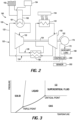
- FIG. 3 graphically illustrates the critical point of a substance, where temperatures and pressures above the critical point will result in a supercritical state.
- the working fluid is supercritical carbon dioxide.
- the system 100 includes components disposed in the fluid loop 120 for performing a sequence of thermodynamic processes involving transfer of heat and work into and out of the system 100, while varying temperature and pressure of the working fluid 122 within the system.
- the system 100 includes a compressor 130 for compressing the supercritical working fluid 122 to an increased pressure.
- the system 100 further includes a heat intake 140 that absorbs heat from a source external to the fluid loop 120 to heat the supercritical working fluid 122.
- the external source is the surface 104 of the flight vehicle 102
- the heat intake 140 is a section of the fluid loop 120 that is located in thermally coupled relation to the surface 104.
- the system 100 further includes a thermal engine 150 that extracts work output 152 from the supercritical working fluid by expanding the supercritical working fluid 122 to a decreased pressure.
- FIG. 2 schematically illustrates the thermal engine 150 as a turbine, other types of thermal engines capable of extracting work output from a heated and pressurized working fluid may be used.
- the work output 152 is in the form of a rotating output shaft of the turbine that is mechanically coupled to the compressor 130 by a shaft 154, thereby to operate the compressor 130.
- the work output 152 may be electrically coupled to the compressor 130, as well as to an electric power generating device.
- the compressor 130 and the thermal engine 150 generally divide the fluid loop 120 into a low pressure leg 124, extending downstream of the thermal engine 150 to an inlet of the compressor 130, and a high pressure leg 126, extending upstream of the thermal engine 150 to an outlet of the compressor 130.
- a recuperator 160 is provided to improve the thermal efficiency of the system 100. As schematically illustrated in FIG. 2 , the recuperator 160 transfers heat from the low pressure leg 124 of the fluid loop 120 to the high pressure leg 126 of the fluid loop. Accordingly, the recuperator 160 alternatively may be referred to as a heat exchanger. By transferring heat to the working fluid 122 prior to further being heated by the heat intake 140 increases the temperature of the working fluid 122 entering the thermal engine 150, thereby increasing the amount of work output 152 that can be extracted from the working fluid.
- a controller 200 may be provided to control operation of the system 100.
- the controller 200 is operably coupled to the compressor 130, and is programmed to execute a method that includes initiating operation of the compressor 130 when one or more operating conditions of the flight vehicle 102 is favorable for maintaining the working fluid 122 in a supercritical state.
- the operating condition is temperature of the surface 104, in which case the controller 200 receives feedback from a sensor 202 configured to detect a temperature of the surface 104 and is programmed to start the compressor 130 when the surface 104 of the flight vehicle 102 exceeds a threshold temperature.
- Exemplary threshold temperatures include, but are not limited to, 500 degrees C, 600 degrees C, 700 degrees C, 800 degrees C, 900 degrees C, and 1000 degrees C.
- the operating condition is a flight speed of the flight vehicle 102, which is indicative of temperature of the surface 104.
- the controller 200 receives an indication of flight speed, such as from an input command or sensor 202 when configured to determine flight speed, and is programmed to start the compressor 130 when the flight vehicle reaches a threshold flight speed.
- Exemplary threshold flight speeds include, but are not limited to, Mach 3, Mach 3.5, Mach 4, and hypersonic speed.
- the controller 200 may be operably coupled to the thermal engine 150.
- controller 200 While the specific hardware implementation of controller 200 is subject to design choices, one particular example includes one or more processors coupled with a current driver.
- the one or more processors may include any electronic circuits and/or optical circuits that are able to perform the functions described herein.
- the processor(s) may perform any functionality described herein for controller 200.
- the processor(s) may include one or more Central Processing Units (CPU), microprocessors, Digital Signal Processors (DSPs), Application-specific Integrated Circuits (ASICs), Programmable Logic Devices (PLD), control circuitry, etc.
- CPU Central Processing Units
- DSPs Digital Signal Processors
- ASICs Application-specific Integrated Circuits
- PLD Programmable Logic Devices
- Some examples of processors include INTEL ® CORE TM processors, Advanced Reduced Instruction Set Computing (RISC) Machines (ARMR) processors, etc.
- the system 100 is configured to maintain the working fluid 122 in a supercritical state during the entire thermodynamic cycle, thereby enabling the use of lighter and more compact turbomachinery.
- the working fluid 122 is carbon dioxide
- the critical temperature is approximately 31 degrees C and the critical pressure is approximately 74 bar.
- Aerodynamic heating of the surface 104 increases with the speed of the flight vehicle 102. For example, at a speed of Mach 3.5, localized portions of the surface 104 reach 400 degrees C or more, which would be sufficient to maintain the working fluid 122 in the supercritical state. At hypersonic speeds in excess of Mach 5, localized portions of the surface 104 may reach 1000 degrees C. Thermodynamic efficiency of the system 100 increases with the temperature of the surface 104.
- the compressor 130 is sized to maintain a pressure of the working fluid 122 above the critical pressure throughout the thermodynamic cycle. Because the working fluid 122 is in a supercritical state, the compressor 130 and the thermal engine 150 may have a reduced size and weight, making the system 100 feasible for use on board the flight vehicle 102. Additionally, the illustrated system 100 is a closed loop system that is provided independent of a propulsion system of the flight vehicle 102.
- the system 100 is further configured to generate electrical power 172.
- the system 100 may include a generator 170 operably coupled to the thermal engine 150.
- the generator 170 receives at least a portion of the work output 152 from the thermal engine 150 and generates the electrical power 172.
- an auxiliary load 180 is operably coupled to the generator 170 and is configured to operate using the electrical power 172.
- the electrical power 172 may be a primary source of power used to operate engine generators.
- the controller 200 further may be operably coupled to the generator 170 and the auxiliary load 180, thereby to control operation or other aspects of those components.
- the system 100 may be referred to alternatively as an integrated cooling and power generation system 100. Because of the thermal efficiency, compact size, and reduced weight afforded by the use of a supercritical working fluid 122, the integrated cooling and power generation system 100 achieves gravimetric and volumetric power densities that are an order of magnitude greater than batteries or other conventional power sources.
- the system 100 further may include a precooler 190 for removing excess heat from the working fluid 122.
- the precooler 190 includes a precooler heat exchanger 191 disposed in the low pressure leg 124 of the fluid loop 120, between the recuperator 160 and the compressor 130. By removing heat from the working fluid 122, the precooler 190 ensures that the temperature of working fluid 122 does not exceed the rated operating temperature range for the compressor 130. The excess heat may be rejected to the surrounding atmosphere or transferred to a secondary fluid in another system on board the flight vehicle 102.
- the precooler 190 further includes a heat sink loop 193 passing through the precooler heat exchanger 191.
- the heat sink loop 193 carries the excess waste heat to a storage structure, such as vessel containing heat sink fluid 192 (e.g., fuel, water, or other fluid carried on board the flight vehicle 102), or a thermal energy storage device 194. Subsequently, the excess waste heat may be used to generate additional power, provide heat to other systems on board the flight vehicle 102, or simply dissipated to the surrounding environment.
- a storage structure such as vessel containing heat sink fluid 192 (e.g., fuel, water, or other fluid carried on board the flight vehicle 102), or a thermal energy storage device 194.
- the excess waste heat may be used to generate additional power, provide heat to other systems on board the flight vehicle 102, or simply dissipated to the surrounding environment.
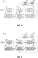
- FIG. 4 is a block diagram 220 illustrating the thermodynamic cycle during operation of the system 100 when the compressor 130 is mechanically driven.
- the working fluid 122 is heated by the surface 104 via the heat intake 140.
- the working fluid 122 is expanded in the thermal engine 150 to obtain the work output 152, which in the illustrated example is a rotating shaft.
- heat from the expanded working fluid 122 is transferred from the low pressure leg 124 of the fluid loop 120 to the high pressure leg 126 by the recuperator 160. In this manner, recuperator 160 harvests heat from the expanded working fluid 122.
- Block 228 illustrates the optional step of transferring excess heat from the working fluid 122 to the heat sink loop 193 using the precooler 190.
- the compressor 130 compresses the working fluid 122 thereby to drive the working fluid 122 through the system (e.g., the fluid loop 120).
- the compressor 130 is mechanically coupled to the thermal engine 150 by the shaft 154, so that the work output 152 directly and mechanically operates (e.g., drives) the compressor 130.
- Block 232 schematically illustrates heating the working fluid 122 via the recuperator 160. In this manner, the temperature of the working fluid 122, which is in a compressed state, is pre-heated. The working fluid 122 then reaches the heat intake 140 at block 222, where the cycle is repeated.
- Block 234 illustrates the optional step of using at least a portion of the work output 152 to drive the generator 170
- block 236 illustrates the optional step of powering the auxiliary load 180 off of the generator. Therefore, in this example, the work output 152 from the thermal engine 150 both mechanically operates the compressor 130 and generates electrical power in the generator 170.
- FIG. 5 is a block diagram 240 illustrating the thermodynamic cycle in a system 100 having an electrically-driven compressor 130.
- the stages of the cycle are identical to those shown in FIG. 4 , except for how the work output 152 is used, and therefore the description of this example will focus only on those differences.
- the system 100 omits the shaft 154 extending between the thermal engine 150 and the compressor 130.
- Driving the generator 170 using the work output 152, illustrated at block 234, is no longer optional but required.
- the compressor 130 is electrically coupled to the generator 170, thereby to drive the compressor 130.
- Powering the auxiliary load 180, shown at block 236, is still optional and may be omitted, in which case the generator 170 is directly coupled to the compressor 130. Therefore, in this example, the work output 152 from the thermal engine 150 is entirely converted to electrical power, which may be used to operate the compressor 130 and, optionally, the auxiliary load 180.
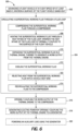
- FIG. 6 is a block diagram illustrating a method 300 of cooling the exterior surface 104 of the high speed flight vehicle 102, with optional power generation.
- the method 300 begins at block 302 by advancing the flight vehicle 102 at a flight speed of at least Mach 3, wherein the surface 104 of the flight vehicle 102 gains heat.
- a supercritical working fluid 122 is circulated through a fluid loop 120.
- Circulation of the working fluid 122 includes, in sequence, compressing the supercritical working fluid 122 through a compressor 130 as shown at block 306, heating the supercritical working fluid 122 through a heat intake 140 of the fluid loop 120 at block 308, wherein the heat intake 140 of the fluid loop 120 is thermally coupled to the surface 104 of the flight vehicle 102, and expanding the supercritical working fluid 122 in a thermal engine 150 at block 310, thereby to generate a work output 152 from the thermal engine 150.
- Circulation of the working fluid 122 through the fluid loop 120 further includes cooling the supercritical working fluid 122 at block 312, and recirculating the supercritical working fluid 122 to the compressor 130 at block 314.
- the method 300 continues at block 316 by operably coupling the work output 152 of the thermal engine 150 to the compressor 130. In this manner, the method 300 absorbs heat from the surface 104 of the flight vehicle 102, thereby allowing the surface 104 to be formed of lower cost and/or lighter materials, and uses the absorbed heat to operate the compressor 130.
- the method 300 may include additional, optional steps for generating electrical power.
- the method 300 may include generating electric power by operably coupling the work output 152 of the thermal engine 150 to a generator 170 at block 318.
- the electrical power from the generator 170 may be used to operate the compressor 130, when the compressor 130 is an electric-powered compressor. Additionally or alternatively, the electrical power from the generator 170 may be used to power an auxiliary load 180, as shown at block 320.
- the method 300 may optionally include an additional step to reduce the temperature of the working fluid 122 to be within a recommended range for the compressor 130. Specifically, the method 300 may include rejecting heat from the supercritical working fluid 122 using a precooler 190 prior to recirculating the supercritical working fluid 122 to the compressor 130, as shown at block 322.
- sequence generally refers to elements (e.g., unit operations) in order. Such order can refer to process order, such as, for example, the order in which a fluid flows from one element to another.
- a compressor, heat storage unit and turbine in sequence includes the compressor upstream of the heat exchange unit, and the heat exchange unit upstream of the turbine.
- a fluid can flow from the compressor to the heat exchange unit and from the heat exchange unit to the turbine.
- a fluid flowing through unit operations in sequence can flow through the unit operations sequentially.
- a sequence of elements can include one or more intervening elements.
- a system comprising a compressor, heat storage unit and turbine in sequence can include an auxiliary tank between the compressor and the heat storage unit.
- a sequence of elements can be cyclical.
- any of the various elements shown in the figures or described herein may be implemented as hardware, software, firmware, or some combination of these.
- an element may be implemented as dedicated hardware.
- Dedicated hardware elements may be referred to as "processors", “controllers”, or some similar terminology.
- processors When provided by a processor, the functions may be provided by a single dedicated processor, by a single shared processor, or by a plurality of individual processors, some of which may be shared.
- processor or “controller” should not be construed to refer exclusively to hardware capable of executing software, and may implicitly include, without limitation, digital signal processor (DSP) hardware, a network processor, application specific integrated circuit (ASIC) or other circuitry, field programmable gate array (FPGA), read only memory (ROM) for storing software, random access memory (RAM), non-volatile storage, logic, or some other physical hardware component or module.
- DSP digital signal processor
- ASIC application specific integrated circuit
- FPGA field programmable gate array
- ROM read only memory
- RAM random access memory
- non-volatile storage logic, or some other physical hardware component or module.
- an element may be implemented as instructions executable by a processor or a computer to perform the functions of the element.
- Some examples of instructions are software, program code, and firmware.
- the instructions are operational when executed by the processor to direct the processor to perform the functions of the element.
- the instructions may be stored on storage devices that are readable by the processor. Some examples of the storage devices are digital or solid-state memories, magnetic storage media such as a magnetic disks and magnetic tapes, hard drives, or optically readable digital data storage media.
Landscapes
- Engineering & Computer Science (AREA)
- Aviation & Aerospace Engineering (AREA)
- Mechanical Engineering (AREA)
- Chemical & Material Sciences (AREA)
- General Engineering & Computer Science (AREA)
- Pulmonology (AREA)
- General Health & Medical Sciences (AREA)
- Health & Medical Sciences (AREA)
- Combustion & Propulsion (AREA)
- Physics & Mathematics (AREA)
- Fluid Mechanics (AREA)
- Chemical Kinetics & Catalysis (AREA)
- Structures Of Non-Positive Displacement Pumps (AREA)
- Engine Equipment That Uses Special Cycles (AREA)
- Cooling, Air Intake And Gas Exhaust, And Fuel Tank Arrangements In Propulsion Units (AREA)
Claims (15)
- Verfahren (300) zum Kühlen einer äußeren Oberfläche (104) eines Flugfahrzeugs (102), wobei das Verfahren aufweist:Vorantreiben (302) des Flugfahrzeugs (102) mit einer Fluggeschwindigkeit von zumindest Mach 3, wobei die Oberfläche (104) des Flugfahrzeugs (102) aerodynamisch geheizt wird;Zirkulieren (304) eines überkritischen Arbeitsfluids (122) durch einen Fluidkreislauf (120) eines geschlossenen Kreislaufsystems, das unabhängig von einem Antriebssystem des Flugkörpers (102) bereitgestellt wird, das nacheinander aufweist:Komprimieren (306) des überkritischen Arbeitsfluids (122) durch einen Kompressor (130);Heizen (308) des überkritischen Arbeitsfluids (122) durch einen Wärmeeinlass (140) des Fluidkreislaufs (120), wobei der Wärmeeinlass (140) des Fluidkreislaufs (120) thermisch mit der Oberfläche (104) des Flugkörpers (102) gekoppelt ist;Expandieren (310) des überkritischen Arbeitsfluids (122) in einer Wärmekraftmaschine (150), um dadurch eine Arbeitsleistung (152) von der Wärmekraftmaschine (150) zu erzeugen;Kühlen (312) des überkritischen Arbeitsfluids (122), wobei das Kühlen (312) des überkritischen Arbeitsfluids (122) einen Wärmeaustausch von einem stromabwärts der Wärmekraftmaschine (150) angeordneten Niederdruckzweig (124) des Fluidkreislaufs (120) zu einem stromaufwärts sowohl der Wärmekraftmaschine (150) als auch der Wärmeaufnahme (140) des Fluidkreislaufs (120) angeordneten Hochdruckzweig (126) des Fluidkreislaufs (120) aufweist; undRezirkulieren (314) des überkritischen Arbeitsfluids (122) zu dem Kompressor (130); undbetriebsfähiges Koppeln (316) der Arbeitsleistung (152) der Wärmekraftmaschine (150) mit dem Kompressor (130).
- Verfahren (300) nach Anspruch 1, des Weiteren aufweisend die Erzeugung von elektrischer Energie (318) durch betriebsfähiges Koppeln der Arbeitsleistung (152) der Wärmekraftmaschine (150) mit einem Generator (170).
- Verfahren (300) nach Anspruch 2, bei dem der Kompressor (130) einen elektrisch betriebenen Kompressor aufweist, der betriebsfähig mit dem Generator (170) gekoppelt ist.
- Verfahren (300) nach Anspruch 2, das des Weiteren aufweist, dass der Generator (170) eine Hilfslast (180) mit Energie versorgt (320).
- Verfahren (300) nach Anspruch 1, bei dem ein Rekuperator (160) bereitgestellt wird, um Wärme von dem Niederdruckzweig (124) des Fluidkreislaufs (120) zu dem Hochdruckzweig (126) des Fluidkreislaufs (120) auszutauschen.
- Verfahren (300) nach einem der Ansprüche 1-6, des Weiteren aufweisend, dass Wärme (322) aus dem überkritischen Arbeitsfluid (122) über einen Vorkühler (190) abgeleitet wird, bevor das überkritische Arbeitsfluid (122) zu dem Kompressor (130) zurückgeführt wird.
- Verfahren (300) nach einem der Ansprüche 1-6, bei dem das überkritische Arbeitsfluid (122) überkritisches Kohlendioxid aufweist.
- System (100) zum Kühlen einer äußeren Oberfläche (104) eines Flugfahrzeugs (102), das sich mit einer Fluggeschwindigkeit von zumindest Mach 3 bewegt, wobei das System (100) ein geschlossenes Kreislaufsystem ist, das unabhängig von einem Antriebssystem des Flugfahrzeugs (102) bereitgestellt wird, wobei das System (100) aufweist:einen Fluidkreislauf (120), der ein überkritisches Arbeitsfluid (122) aufweist, wobei der Fluidkreislauf (120) nacheinander aufweist,einen Kompressor (130) zum Komprimieren des überkritischen Arbeitsfluids (122);einen Wärmeeinlass (140), der in thermisch gekoppeltem Verhältnis zur Oberfläche (104) des Flugfahrzeugs (102) angeordnet ist, um das überkritische Arbeitsfluid (122) zu erhitzen;eine Wärmekraftmaschine (150) zum Expandieren des überkritischen Arbeitsfluids (122) und zum Erzeugen einer Arbeitsleistung (152), wobei der Arbeitsleistung (152) betriebsfähig mit dem Kompressor (130) gekoppelt ist; undeinen Rekuperator (160) zum Austausch von Wärme von einem Niederdruckstrang (124) des Fluidkreislaufs (120), der stromabwärts der Wärmekraftmaschine (150) angeordnet ist, zu einem Hochdruckstrang (126) des Fluidkreislaufs (120), der stromaufwärts sowohl der Wärmekraftmaschine (150) als auch der Wärmeaufnahme (140) des Fluidkreislaufs (120) angeordnet ist.
- System (100) nach Anspruch 8, das des Weiteren einen Generator (170) aufweist, der betriebsfähig mit der Wärmekraftmaschine (150) gekoppelt ist und ausgebildet ist, um zumindest einen Abschnitt der Arbeitsleistung (152) zu empfangen und elektrische Energie (172) zu erzeugen.
- System (100) nach Anspruch 9, bei dem der Kompressor (130) einen elektrisch betriebenen Kompressor aufweist, der mit dem Generator (170) gekoppelt ist.
- System (100) nach einem der Ansprüche 8-10, des Weiteren aufweisend einen Vorkühler (190), der betriebsfähig mit dem Niederdruckzweig (124) des Fluidkreislaufs (120) zwischen dem Rekuperator (160) und dem Kompressor (130) gekoppelt ist.
- System (100) nach Anspruch 11, wobei der Vorkühler eine Wärmesenke (192) oder eine Vorrichtung zur Speicherung thermischer Energie (194) aufweist.
- System (100) nach einem der Ansprüche 8 bis 12, ferner aufweisend eine Steuerung (200), die betriebsfähig mit dem Kompressor (130) gekoppelt ist, wobei die Steuerung (200) so programmiert ist, dass sie ein Verfahren ausführt, das das Beginnen des Betriebs des Kompressors (130) aufweist, wenn ein Betriebszustand des Flugfahrzeugs einen Schwellwert überschreitet.
- System (100) nach Anspruch 13, wobei der Betriebszustand des Flugfahrzeugs (102) eine Temperatur der Oberfläche (104) aufweist.
- System (100) nach Anspruch 13, bei dem der Betriebszustand des Flugfahrzeugs (102) eine Fluggeschwindigkeit des Flugfahrzeugs (102) aufweist.
Applications Claiming Priority (1)
| Application Number | Priority Date | Filing Date | Title |
|---|---|---|---|
| US16/457,418 US11465766B2 (en) | 2019-06-28 | 2019-06-28 | Systems and methods for cooling and generating power on high speed flight vehicles |
Publications (2)
| Publication Number | Publication Date |
|---|---|
| EP3757010A1 EP3757010A1 (de) | 2020-12-30 |
| EP3757010B1 true EP3757010B1 (de) | 2023-08-16 |
Family
ID=70613712
Family Applications (1)
| Application Number | Title | Priority Date | Filing Date |
|---|---|---|---|
| EP20173365.6A Active EP3757010B1 (de) | 2019-06-28 | 2020-05-07 | Systeme und verfahren zur kühlung und erzeugung von strom bei hochgeschwindigkeitsluftfahrzeugen |
Country Status (6)
| Country | Link |
|---|---|
| US (1) | US11465766B2 (de) |
| EP (1) | EP3757010B1 (de) |
| JP (1) | JP2021020668A (de) |
| CN (1) | CN112141345B (de) |
| CA (1) | CA3081951C (de) |
| RU (1) | RU2020114714A (de) |
Families Citing this family (10)
| Publication number | Priority date | Publication date | Assignee | Title |
|---|---|---|---|---|
| US11465766B2 (en) | 2019-06-28 | 2022-10-11 | The Boeing Company | Systems and methods for cooling and generating power on high speed flight vehicles |
| EP4001599B8 (de) | 2020-11-23 | 2023-04-12 | The Boeing Company | Verfahren und systeme zur leistungs- und wärmeverwaltung mit kombinierter zyklusarchitektur |
| EP4001613B1 (de) | 2020-11-23 | 2024-06-19 | The Boeing Company | Verfahren und systeme zur erzeugung von strom und zur wärmeverwaltung mit doppelschleifenarchitektur |
| US20230373644A1 (en) * | 2022-05-23 | 2023-11-23 | Hamilton Sundstrand Corporation | Vapor compression system for aerospace applications |
| US12497188B2 (en) | 2023-08-14 | 2025-12-16 | The Boeing Company | Liquid hydrogen feed system for fuel cell powered aircraft |
| CN117125244B (zh) * | 2023-09-22 | 2024-08-20 | 清华大学 | 高速飞行器分区段热防护结构 |
| US12589872B2 (en) * | 2023-09-29 | 2026-03-31 | The Boeing Company | Method and system for reducing a temperature differential across a flight vehicle |
| US12345212B2 (en) | 2023-11-21 | 2025-07-01 | Rtx Corporation | Turbine engine with auxiliary coolant injection |
| CN119590603B (zh) * | 2024-12-02 | 2026-03-10 | 东南大学 | 高速飞行器热疏导-发电集成装置 |
| CN119749834A (zh) * | 2024-12-26 | 2025-04-04 | 西南科技大学 | 一种抑制超高速运动物体表面等离子体的方法和装置 |
Family Cites Families (50)
| Publication number | Priority date | Publication date | Assignee | Title |
|---|---|---|---|---|
| JP2002022298A (ja) | 2000-07-04 | 2002-01-23 | Matsushita Electric Ind Co Ltd | 冷凍サイクル装置とその制御方法 |
| JP2006523294A (ja) * | 2003-01-22 | 2006-10-12 | ヴァスト・パワー・システムズ・インコーポレーテッド | 反応装置 |
| CN101124438B (zh) * | 2005-02-18 | 2010-08-04 | 卡里尔公司 | 具有热回收的co2制冷设备 |
| US7963100B2 (en) | 2005-05-25 | 2011-06-21 | Alliant Techsystems Inc. | Cooling system for high-speed vehicles and method of cooling high-speed vehicles |
| WO2007035298A2 (en) * | 2005-09-09 | 2007-03-29 | Lugg Richard H | Advanced hypersonic magnetic jet/electric turbine engine |
| US7624592B2 (en) | 2006-05-17 | 2009-12-01 | Northrop Grumman Corporation | Flexible power and thermal architectures using a common machine |
| US7607318B2 (en) | 2006-05-25 | 2009-10-27 | Honeywell International Inc. | Integrated environmental control and auxiliary power system for an aircraft |
| JP2009191611A (ja) * | 2007-09-13 | 2009-08-27 | Hiroyasu Tanigawa | 各種エネルギ保存サイクル合体機関 |
| US8127555B2 (en) | 2007-12-13 | 2012-03-06 | Pratt & Whitney Rocketdyne, Inc. | Flowpath heat exchanger for thermal management and power generation within a hypersonic vehicle |
| CN101301931A (zh) * | 2008-04-28 | 2008-11-12 | 全力 | 复合涡流的制造方法、制造设备及复合涡流飞行器 |
| US9181900B1 (en) * | 2008-08-19 | 2015-11-10 | Sonic Blue Aerospace, Inc. | Fully advanced superconducting segmented turbo-electric rotormachine (fasster) |
| US8327651B2 (en) * | 2009-07-07 | 2012-12-11 | Hamilton Sundstrand Corporation | Transcritical fluid cooling for aerospace applications |
| US20170292412A1 (en) * | 2009-10-27 | 2017-10-12 | Eduardo E. Fonseca | Aircraft Engine Heat Recovery System to Power Environmental Control Systems |
| CA2792331C (en) * | 2010-03-05 | 2017-12-12 | Exxonmobil Upstream Research Company | Flexible liquefied natural gas plant |
| US8522572B2 (en) | 2010-07-01 | 2013-09-03 | General Electric Company | Adaptive power and thermal management system |
| GB2499576A (en) * | 2011-11-29 | 2013-08-28 | Eaton Aerospace Ltd | Aircraft on board inert gas generation system |
| US10006363B2 (en) * | 2012-12-28 | 2018-06-26 | General Electric Company | System and method for aviation electric power production |
| US20150337730A1 (en) * | 2012-12-28 | 2015-11-26 | General Electric Company | Turbine engine assemblies |
| US9718553B2 (en) | 2013-03-14 | 2017-08-01 | Rolls-Royce North America Technologies, Inc. | Adaptive trans-critical CO2 cooling systems for aerospace applications |
| JP2016512862A (ja) * | 2013-03-15 | 2016-05-09 | ゼネラル・エレクトリック・カンパニイ | 航空機エンジン向けのエネルギー効率のよい制御されたクライオ燃料の蒸発 |
| WO2014153570A2 (en) * | 2013-03-15 | 2014-09-25 | Transtar Group, Ltd | New and improved system for processing various chemicals and materials |
| US20150315971A1 (en) | 2013-10-21 | 2015-11-05 | Government Of The United States As Represented By The Secretary Of The Air Force | High-speed vehicle power and thermal management system and methods of use therefor |
| US9739200B2 (en) | 2013-12-30 | 2017-08-22 | Rolls-Royce Corporation | Cooling systems for high mach applications |
| US9810158B2 (en) * | 2014-04-01 | 2017-11-07 | The Boeing Company | Bleed air systems for use with aircraft and related methods |
| US10054051B2 (en) * | 2014-04-01 | 2018-08-21 | The Boeing Company | Bleed air systems for use with aircraft and related methods |
| US20150315966A1 (en) | 2014-05-01 | 2015-11-05 | The Boeing Company | Hypersonic Vehicle Base Drag Reduction and Improved Inlet Performance Through Venting Forebody Bleed Air to Base Area Using Open Core Ceramic Composites |
| NO3136728T3 (de) * | 2014-06-30 | 2018-07-28 | ||
| CN107428415B (zh) * | 2015-03-30 | 2021-11-19 | 空中客车德国运营有限责任公司 | 具有冗余的有效引气系统的飞行器 |
| US11208893B2 (en) * | 2015-05-25 | 2021-12-28 | Socpra Sciences Et Genie S.E.C. | High temperature ceramic rotary turbomachinery |
| US10100744B2 (en) * | 2015-06-19 | 2018-10-16 | The Boeing Company | Aircraft bleed air and engine starter systems and related methods |
| US9758235B2 (en) | 2015-10-13 | 2017-09-12 | The Boeing Company | Thermal insulation system, aircraft, and vehicle having same |
| DE102015223548A1 (de) * | 2015-11-27 | 2017-06-01 | Airbus Operations Gmbh | Flugzeugklimaanlage mit Umgebungsluftzufuhr und Verfahren zum Betreiben einer derartigen Flugzeugklimaanlage |
| US20170217592A1 (en) * | 2016-02-01 | 2017-08-03 | General Electric Company | Aircraft Thermal Management System |
| US10364744B2 (en) * | 2016-06-08 | 2019-07-30 | Rolls-Royce Corporation | Deep heat recovery gas turbine engine |
| CN106640242B (zh) * | 2016-09-19 | 2018-02-09 | 清华大学 | 高超声速飞行器发动机热量回收发电系统及其控制方法 |
| US10329022B2 (en) * | 2016-10-31 | 2019-06-25 | Honeywell International Inc. | Adjustable sensor or sensor network to selectively enhance identification of select chemical species |
| US10221775B2 (en) | 2016-12-29 | 2019-03-05 | Malta Inc. | Use of external air for closed cycle inventory control |
| US20180215475A1 (en) | 2017-02-01 | 2018-08-02 | General Electric Company | Systems and Methods for Integrated Power and Thermal Management in a Turbine-Powered Aircraft |
| US10239624B2 (en) * | 2017-02-15 | 2019-03-26 | The Boeing Company | Reverse air cycle machine (RACM) thermal management systems and methods |
| CN107150810B (zh) | 2017-04-06 | 2018-06-22 | 清华大学 | 飞行器热部件的防护系统 |
| US10926480B2 (en) | 2017-09-05 | 2021-02-23 | The Boeing Company | Methods for manufacturing components having spatially graded properties |
| CN107914862B (zh) * | 2017-11-20 | 2020-09-18 | 北京临近空间飞行器系统工程研究所 | 一种全主动冷却高超声速飞行器 |
| CN108298061B (zh) | 2018-01-30 | 2020-03-24 | 南京普国科技有限公司 | 高超声速飞行器及其热防护和热生电装置 |
| CN108657442B (zh) * | 2018-05-16 | 2020-11-24 | 中国航发湖南动力机械研究所 | 飞行器及热防护系统 |
| CN108750123B (zh) | 2018-06-07 | 2020-10-23 | 北京航空航天大学 | 适用于高超声速飞行器的热能综合管理系统及飞行器 |
| CN109823510A (zh) * | 2019-03-06 | 2019-05-31 | 中南大学 | 高超声速飞行器及其热防护结构与冷却剂循环系统 |
| CN109989833A (zh) | 2019-04-24 | 2019-07-09 | 北京航空航天大学 | 一种用于高超声速飞行器或发动机的综合热管理系统 |
| US11465766B2 (en) | 2019-06-28 | 2022-10-11 | The Boeing Company | Systems and methods for cooling and generating power on high speed flight vehicles |
| US11969796B2 (en) | 2020-01-03 | 2024-04-30 | The Boeing Company | Tuned multilayered material systems and methods for manufacturing |
| US11571742B2 (en) | 2020-01-03 | 2023-02-07 | The Boeing Company | Tuned multilayered material systems and methods for manufacturing |
-
2019
- 2019-06-28 US US16/457,418 patent/US11465766B2/en active Active
-
2020
- 2020-04-24 RU RU2020114714A patent/RU2020114714A/ru unknown
- 2020-05-07 EP EP20173365.6A patent/EP3757010B1/de active Active
- 2020-05-22 CN CN202010439842.2A patent/CN112141345B/zh active Active
- 2020-06-03 CA CA3081951A patent/CA3081951C/en active Active
- 2020-06-29 JP JP2020111068A patent/JP2021020668A/ja active Pending
Also Published As
| Publication number | Publication date |
|---|---|
| EP3757010A1 (de) | 2020-12-30 |
| US20200407072A1 (en) | 2020-12-31 |
| CN112141345A (zh) | 2020-12-29 |
| RU2020114714A (ru) | 2021-10-25 |
| CA3081951C (en) | 2025-08-05 |
| JP2021020668A (ja) | 2021-02-18 |
| CA3081951A1 (en) | 2020-12-28 |
| CN112141345B (zh) | 2025-05-20 |
| US11465766B2 (en) | 2022-10-11 |
Similar Documents
| Publication | Publication Date | Title |
|---|---|---|
| CA3081951C (en) | COOLING AND POWER GENERATION SYSTEMS AND METHODS FOR VEHICLES FLYING IN HIGH CRUISE MODE | |
| CN109677639B (zh) | 基于闭式布雷顿循环的空间大功率核动力系统 | |
| EP3363739B1 (de) | Umgekehrte luftkreislaufmaschinen (racm)-thermomanagementsysteme und verfahren | |
| CN108750123B (zh) | 适用于高超声速飞行器的热能综合管理系统及飞行器 | |
| US12595759B2 (en) | Methods and systems for generating power and thermal management having dual loop architecture | |
| EP2994385B1 (de) | Adaptive transkritische co2-kühlsysteme für luft- und raumfahrtanwendungen | |
| Zegenhagen et al. | Feasibility analysis of an exhaust gas waste heat driven jet-ejector cooling system for charge air cooling of turbocharged gasoline engines | |
| US11598285B2 (en) | Methods and systems for generating power and thermal management having combined cycle architecture | |
| CN220929493U (zh) | 一种水侧定压水蓄热方式的压缩空气储能系统 | |
| CN113153537B (zh) | 一种应用于高超声速飞机的三轮冷却-制冷循环冷却系统 | |
| US4265397A (en) | Combined fresh air regenerator and air cycle heat pump | |
| CN116692013B (zh) | 一种适用于全电飞机的组合式循环制冷系统及其工作方法 | |
| CN112922684A (zh) | 结合热光伏技术的多模式发电布雷顿循环系统及工作方法 | |
| Yang et al. | Optimization of a Reverse-Brayton cycle with inter-cooling and regeneration | |
| CN113882920B (zh) | 一种开式co2半布雷顿冷却及发电系统 | |
| EP4530182A1 (de) | Verfahren und system zur verringerung eines temperaturdifferentials über ein flugzeug | |
| WO2026025752A1 (zh) | 新能源车辆的电池冷却系统及车辆 | |
| Giuffré et al. | Thermal Management System Architecture for the Powertrain of a 90-Seater Battery-Electric Aircraft | |
| CN119305733B (zh) | 一种高温燃油热沉半闭式空气循环飞机环控系统和方法 | |
| CN119408719B (zh) | 一种超导氢电推进飞机热管理系统及工作方法 | |
| EP4342798B1 (de) | Niederdruckluftkreislauf | |
| EP4456212B1 (de) | Stromerzeugungssystem | |
| CN119468536A (zh) | 一种综合供能系统及方法 |
Legal Events
| Date | Code | Title | Description |
|---|---|---|---|
| PUAI | Public reference made under article 153(3) epc to a published international application that has entered the european phase |
Free format text: ORIGINAL CODE: 0009012 |
|
| STAA | Information on the status of an ep patent application or granted ep patent |
Free format text: STATUS: THE APPLICATION HAS BEEN PUBLISHED |
|
| AK | Designated contracting states |
Kind code of ref document: A1 Designated state(s): AL AT BE BG CH CY CZ DE DK EE ES FI FR GB GR HR HU IE IS IT LI LT LU LV MC MK MT NL NO PL PT RO RS SE SI SK SM TR |
|
| AX | Request for extension of the european patent |
Extension state: BA ME |
|
| STAA | Information on the status of an ep patent application or granted ep patent |
Free format text: STATUS: REQUEST FOR EXAMINATION WAS MADE |
|
| 17P | Request for examination filed |
Effective date: 20210621 |
|
| RBV | Designated contracting states (corrected) |
Designated state(s): AL AT BE BG CH CY CZ DE DK EE ES FI FR GB GR HR HU IE IS IT LI LT LU LV MC MK MT NL NO PL PT RO RS SE SI SK SM TR |
|
| STAA | Information on the status of an ep patent application or granted ep patent |
Free format text: STATUS: EXAMINATION IS IN PROGRESS |
|
| 17Q | First examination report despatched |
Effective date: 20220221 |
|
| GRAP | Despatch of communication of intention to grant a patent |
Free format text: ORIGINAL CODE: EPIDOSNIGR1 |
|
| STAA | Information on the status of an ep patent application or granted ep patent |
Free format text: STATUS: GRANT OF PATENT IS INTENDED |
|
| RAP3 | Party data changed (applicant data changed or rights of an application transferred) |
Owner name: THE BOEING COMPANY |
|
| INTG | Intention to grant announced |
Effective date: 20230321 |
|
| P01 | Opt-out of the competence of the unified patent court (upc) registered |
Effective date: 20230508 |
|
| GRAS | Grant fee paid |
Free format text: ORIGINAL CODE: EPIDOSNIGR3 |
|
| GRAA | (expected) grant |
Free format text: ORIGINAL CODE: 0009210 |
|
| STAA | Information on the status of an ep patent application or granted ep patent |
Free format text: STATUS: THE PATENT HAS BEEN GRANTED |
|
| AK | Designated contracting states |
Kind code of ref document: B1 Designated state(s): AL AT BE BG CH CY CZ DE DK EE ES FI FR GB GR HR HU IE IS IT LI LT LU LV MC MK MT NL NO PL PT RO RS SE SI SK SM TR |
|
| REG | Reference to a national code |
Ref country code: CH Ref legal event code: EP |
|
| REG | Reference to a national code |
Ref country code: DE Ref legal event code: R096 Ref document number: 602020015698 Country of ref document: DE |
|
| REG | Reference to a national code |
Ref country code: IE Ref legal event code: FG4D |
|
| REG | Reference to a national code |
Ref country code: LT Ref legal event code: MG9D |
|
| REG | Reference to a national code |
Ref country code: NL Ref legal event code: MP Effective date: 20230816 |
|
| REG | Reference to a national code |
Ref country code: AT Ref legal event code: MK05 Ref document number: 1599835 Country of ref document: AT Kind code of ref document: T Effective date: 20230816 |
|
| PG25 | Lapsed in a contracting state [announced via postgrant information from national office to epo] |
Ref country code: GR Free format text: LAPSE BECAUSE OF FAILURE TO SUBMIT A TRANSLATION OF THE DESCRIPTION OR TO PAY THE FEE WITHIN THE PRESCRIBED TIME-LIMIT Effective date: 20231117 |
|
| PG25 | Lapsed in a contracting state [announced via postgrant information from national office to epo] |
Ref country code: IS Free format text: LAPSE BECAUSE OF FAILURE TO SUBMIT A TRANSLATION OF THE DESCRIPTION OR TO PAY THE FEE WITHIN THE PRESCRIBED TIME-LIMIT Effective date: 20231216 |
|
| PG25 | Lapsed in a contracting state [announced via postgrant information from national office to epo] |
Ref country code: SE Free format text: LAPSE BECAUSE OF FAILURE TO SUBMIT A TRANSLATION OF THE DESCRIPTION OR TO PAY THE FEE WITHIN THE PRESCRIBED TIME-LIMIT Effective date: 20230816 Ref country code: RS Free format text: LAPSE BECAUSE OF FAILURE TO SUBMIT A TRANSLATION OF THE DESCRIPTION OR TO PAY THE FEE WITHIN THE PRESCRIBED TIME-LIMIT Effective date: 20230816 Ref country code: PT Free format text: LAPSE BECAUSE OF FAILURE TO SUBMIT A TRANSLATION OF THE DESCRIPTION OR TO PAY THE FEE WITHIN THE PRESCRIBED TIME-LIMIT Effective date: 20231218 Ref country code: NO Free format text: LAPSE BECAUSE OF FAILURE TO SUBMIT A TRANSLATION OF THE DESCRIPTION OR TO PAY THE FEE WITHIN THE PRESCRIBED TIME-LIMIT Effective date: 20231116 Ref country code: NL Free format text: LAPSE BECAUSE OF FAILURE TO SUBMIT A TRANSLATION OF THE DESCRIPTION OR TO PAY THE FEE WITHIN THE PRESCRIBED TIME-LIMIT Effective date: 20230816 Ref country code: LV Free format text: LAPSE BECAUSE OF FAILURE TO SUBMIT A TRANSLATION OF THE DESCRIPTION OR TO PAY THE FEE WITHIN THE PRESCRIBED TIME-LIMIT Effective date: 20230816 Ref country code: LT Free format text: LAPSE BECAUSE OF FAILURE TO SUBMIT A TRANSLATION OF THE DESCRIPTION OR TO PAY THE FEE WITHIN THE PRESCRIBED TIME-LIMIT Effective date: 20230816 Ref country code: IS Free format text: LAPSE BECAUSE OF FAILURE TO SUBMIT A TRANSLATION OF THE DESCRIPTION OR TO PAY THE FEE WITHIN THE PRESCRIBED TIME-LIMIT Effective date: 20231216 Ref country code: HR Free format text: LAPSE BECAUSE OF FAILURE TO SUBMIT A TRANSLATION OF THE DESCRIPTION OR TO PAY THE FEE WITHIN THE PRESCRIBED TIME-LIMIT Effective date: 20230816 Ref country code: GR Free format text: LAPSE BECAUSE OF FAILURE TO SUBMIT A TRANSLATION OF THE DESCRIPTION OR TO PAY THE FEE WITHIN THE PRESCRIBED TIME-LIMIT Effective date: 20231117 Ref country code: FI Free format text: LAPSE BECAUSE OF FAILURE TO SUBMIT A TRANSLATION OF THE DESCRIPTION OR TO PAY THE FEE WITHIN THE PRESCRIBED TIME-LIMIT Effective date: 20230816 Ref country code: AT Free format text: LAPSE BECAUSE OF FAILURE TO SUBMIT A TRANSLATION OF THE DESCRIPTION OR TO PAY THE FEE WITHIN THE PRESCRIBED TIME-LIMIT Effective date: 20230816 |
|
| PG25 | Lapsed in a contracting state [announced via postgrant information from national office to epo] |
Ref country code: PL Free format text: LAPSE BECAUSE OF FAILURE TO SUBMIT A TRANSLATION OF THE DESCRIPTION OR TO PAY THE FEE WITHIN THE PRESCRIBED TIME-LIMIT Effective date: 20230816 |
|
| PG25 | Lapsed in a contracting state [announced via postgrant information from national office to epo] |
Ref country code: ES Free format text: LAPSE BECAUSE OF FAILURE TO SUBMIT A TRANSLATION OF THE DESCRIPTION OR TO PAY THE FEE WITHIN THE PRESCRIBED TIME-LIMIT Effective date: 20230816 |
|
| PG25 | Lapsed in a contracting state [announced via postgrant information from national office to epo] |
Ref country code: SM Free format text: LAPSE BECAUSE OF FAILURE TO SUBMIT A TRANSLATION OF THE DESCRIPTION OR TO PAY THE FEE WITHIN THE PRESCRIBED TIME-LIMIT Effective date: 20230816 Ref country code: RO Free format text: LAPSE BECAUSE OF FAILURE TO SUBMIT A TRANSLATION OF THE DESCRIPTION OR TO PAY THE FEE WITHIN THE PRESCRIBED TIME-LIMIT Effective date: 20230816 Ref country code: ES Free format text: LAPSE BECAUSE OF FAILURE TO SUBMIT A TRANSLATION OF THE DESCRIPTION OR TO PAY THE FEE WITHIN THE PRESCRIBED TIME-LIMIT Effective date: 20230816 Ref country code: EE Free format text: LAPSE BECAUSE OF FAILURE TO SUBMIT A TRANSLATION OF THE DESCRIPTION OR TO PAY THE FEE WITHIN THE PRESCRIBED TIME-LIMIT Effective date: 20230816 Ref country code: DK Free format text: LAPSE BECAUSE OF FAILURE TO SUBMIT A TRANSLATION OF THE DESCRIPTION OR TO PAY THE FEE WITHIN THE PRESCRIBED TIME-LIMIT Effective date: 20230816 Ref country code: CZ Free format text: LAPSE BECAUSE OF FAILURE TO SUBMIT A TRANSLATION OF THE DESCRIPTION OR TO PAY THE FEE WITHIN THE PRESCRIBED TIME-LIMIT Effective date: 20230816 Ref country code: SK Free format text: LAPSE BECAUSE OF FAILURE TO SUBMIT A TRANSLATION OF THE DESCRIPTION OR TO PAY THE FEE WITHIN THE PRESCRIBED TIME-LIMIT Effective date: 20230816 |
|
| REG | Reference to a national code |
Ref country code: DE Ref legal event code: R097 Ref document number: 602020015698 Country of ref document: DE |
|
| PLBE | No opposition filed within time limit |
Free format text: ORIGINAL CODE: 0009261 |
|
| STAA | Information on the status of an ep patent application or granted ep patent |
Free format text: STATUS: NO OPPOSITION FILED WITHIN TIME LIMIT |
|
| 26N | No opposition filed |
Effective date: 20240517 |
|
| PG25 | Lapsed in a contracting state [announced via postgrant information from national office to epo] |
Ref country code: IT Free format text: LAPSE BECAUSE OF FAILURE TO SUBMIT A TRANSLATION OF THE DESCRIPTION OR TO PAY THE FEE WITHIN THE PRESCRIBED TIME-LIMIT Effective date: 20230816 Ref country code: SI Free format text: LAPSE BECAUSE OF FAILURE TO SUBMIT A TRANSLATION OF THE DESCRIPTION OR TO PAY THE FEE WITHIN THE PRESCRIBED TIME-LIMIT Effective date: 20230816 |
|
| PG25 | Lapsed in a contracting state [announced via postgrant information from national office to epo] |
Ref country code: BG Free format text: LAPSE BECAUSE OF FAILURE TO SUBMIT A TRANSLATION OF THE DESCRIPTION OR TO PAY THE FEE WITHIN THE PRESCRIBED TIME-LIMIT Effective date: 20230816 |
|
| PG25 | Lapsed in a contracting state [announced via postgrant information from national office to epo] |
Ref country code: BG Free format text: LAPSE BECAUSE OF FAILURE TO SUBMIT A TRANSLATION OF THE DESCRIPTION OR TO PAY THE FEE WITHIN THE PRESCRIBED TIME-LIMIT Effective date: 20230816 |
|
| REG | Reference to a national code |
Ref country code: CH Ref legal event code: PL |
|
| PG25 | Lapsed in a contracting state [announced via postgrant information from national office to epo] |
Ref country code: MC Free format text: LAPSE BECAUSE OF FAILURE TO SUBMIT A TRANSLATION OF THE DESCRIPTION OR TO PAY THE FEE WITHIN THE PRESCRIBED TIME-LIMIT Effective date: 20230816 |
|
| PG25 | Lapsed in a contracting state [announced via postgrant information from national office to epo] |
Ref country code: LU Free format text: LAPSE BECAUSE OF NON-PAYMENT OF DUE FEES Effective date: 20240507 |
|
| PG25 | Lapsed in a contracting state [announced via postgrant information from national office to epo] |
Ref country code: MC Free format text: LAPSE BECAUSE OF FAILURE TO SUBMIT A TRANSLATION OF THE DESCRIPTION OR TO PAY THE FEE WITHIN THE PRESCRIBED TIME-LIMIT Effective date: 20230816 Ref country code: LU Free format text: LAPSE BECAUSE OF NON-PAYMENT OF DUE FEES Effective date: 20240507 Ref country code: CH Free format text: LAPSE BECAUSE OF NON-PAYMENT OF DUE FEES Effective date: 20240531 |
|
| REG | Reference to a national code |
Ref country code: BE Ref legal event code: MM Effective date: 20240531 |
|
| PG25 | Lapsed in a contracting state [announced via postgrant information from national office to epo] |
Ref country code: IE Free format text: LAPSE BECAUSE OF NON-PAYMENT OF DUE FEES Effective date: 20240507 |
|
| PG25 | Lapsed in a contracting state [announced via postgrant information from national office to epo] |
Ref country code: BE Free format text: LAPSE BECAUSE OF NON-PAYMENT OF DUE FEES Effective date: 20240531 |
|
| PGFP | Annual fee paid to national office [announced via postgrant information from national office to epo] |
Ref country code: DE Payment date: 20250529 Year of fee payment: 6 |
|
| PGFP | Annual fee paid to national office [announced via postgrant information from national office to epo] |
Ref country code: GB Payment date: 20250527 Year of fee payment: 6 |
|
| PGFP | Annual fee paid to national office [announced via postgrant information from national office to epo] |
Ref country code: FR Payment date: 20250526 Year of fee payment: 6 |
|
| PG25 | Lapsed in a contracting state [announced via postgrant information from national office to epo] |
Ref country code: CY Free format text: LAPSE BECAUSE OF FAILURE TO SUBMIT A TRANSLATION OF THE DESCRIPTION OR TO PAY THE FEE WITHIN THE PRESCRIBED TIME-LIMIT; INVALID AB INITIO Effective date: 20200507 |
|
| PG25 | Lapsed in a contracting state [announced via postgrant information from national office to epo] |
Ref country code: HU Free format text: LAPSE BECAUSE OF FAILURE TO SUBMIT A TRANSLATION OF THE DESCRIPTION OR TO PAY THE FEE WITHIN THE PRESCRIBED TIME-LIMIT; INVALID AB INITIO Effective date: 20200507 |