EP3757004B1 - Aéronef vtol avec des poutres de connexion d'ailes - Google Patents
Aéronef vtol avec des poutres de connexion d'ailes Download PDFInfo
- Publication number
- EP3757004B1 EP3757004B1 EP19182947.2A EP19182947A EP3757004B1 EP 3757004 B1 EP3757004 B1 EP 3757004B1 EP 19182947 A EP19182947 A EP 19182947A EP 3757004 B1 EP3757004 B1 EP 3757004B1
- Authority
- EP
- European Patent Office
- Prior art keywords
- aircraft
- wing
- aft
- propulsion units
- forward flight
- Prior art date
- Legal status (The legal status is an assumption and is not a legal conclusion. Google has not performed a legal analysis and makes no representation as to the accuracy of the status listed.)
- Active
Links
- 239000003381 stabilizer Substances 0.000 claims description 22
- 230000005484 gravity Effects 0.000 claims description 12
- 230000007423 decrease Effects 0.000 claims description 4
- 230000001419 dependent effect Effects 0.000 claims description 2
- 230000000087 stabilizing effect Effects 0.000 description 6
- 230000000903 blocking effect Effects 0.000 description 5
- 230000000694 effects Effects 0.000 description 5
- 230000008901 benefit Effects 0.000 description 4
- 230000009286 beneficial effect Effects 0.000 description 2
- 241000689227 Cora <basidiomycete fungus> Species 0.000 description 1
- 239000005441 aurora Substances 0.000 description 1
- 230000003247 decreasing effect Effects 0.000 description 1
- 238000011161 development Methods 0.000 description 1
- 230000018109 developmental process Effects 0.000 description 1
- 238000009434 installation Methods 0.000 description 1
- 230000002452 interceptive effect Effects 0.000 description 1
- 230000007704 transition Effects 0.000 description 1
Images


Classifications
-
- B—PERFORMING OPERATIONS; TRANSPORTING
- B64—AIRCRAFT; AVIATION; COSMONAUTICS
- B64C—AEROPLANES; HELICOPTERS
- B64C29/00—Aircraft capable of landing or taking-off vertically, e.g. vertical take-off and landing [VTOL] aircraft
- B64C29/0008—Aircraft capable of landing or taking-off vertically, e.g. vertical take-off and landing [VTOL] aircraft having its flight directional axis horizontal when grounded
- B64C29/0016—Aircraft capable of landing or taking-off vertically, e.g. vertical take-off and landing [VTOL] aircraft having its flight directional axis horizontal when grounded the lift during taking-off being created by free or ducted propellers or by blowers
- B64C29/0025—Aircraft capable of landing or taking-off vertically, e.g. vertical take-off and landing [VTOL] aircraft having its flight directional axis horizontal when grounded the lift during taking-off being created by free or ducted propellers or by blowers the propellers being fixed relative to the fuselage
-
- B—PERFORMING OPERATIONS; TRANSPORTING
- B64—AIRCRAFT; AVIATION; COSMONAUTICS
- B64C—AEROPLANES; HELICOPTERS
- B64C27/00—Rotorcraft; Rotors peculiar thereto
- B64C27/22—Compound rotorcraft, i.e. aircraft using in flight the features of both aeroplane and rotorcraft
- B64C27/26—Compound rotorcraft, i.e. aircraft using in flight the features of both aeroplane and rotorcraft characterised by provision of fixed wings
-
- B—PERFORMING OPERATIONS; TRANSPORTING
- B64—AIRCRAFT; AVIATION; COSMONAUTICS
- B64C—AEROPLANES; HELICOPTERS
- B64C11/00—Propellers, e.g. of ducted type; Features common to propellers and rotors for rotorcraft
- B64C11/46—Arrangements of, or constructional features peculiar to, multiple propellers
-
- B—PERFORMING OPERATIONS; TRANSPORTING
- B64—AIRCRAFT; AVIATION; COSMONAUTICS
- B64C—AEROPLANES; HELICOPTERS
- B64C3/00—Wings
- B64C3/18—Spars; Ribs; Stringers
- B64C3/182—Stringers, longerons
-
- B—PERFORMING OPERATIONS; TRANSPORTING
- B64—AIRCRAFT; AVIATION; COSMONAUTICS
- B64C—AEROPLANES; HELICOPTERS
- B64C39/00—Aircraft not otherwise provided for
- B64C39/06—Aircraft not otherwise provided for having disc- or ring-shaped wings
- B64C39/068—Aircraft not otherwise provided for having disc- or ring-shaped wings having multiple wings joined at the tips
-
- B—PERFORMING OPERATIONS; TRANSPORTING
- B64—AIRCRAFT; AVIATION; COSMONAUTICS
- B64C—AEROPLANES; HELICOPTERS
- B64C39/00—Aircraft not otherwise provided for
- B64C39/08—Aircraft not otherwise provided for having multiple wings
-
- B—PERFORMING OPERATIONS; TRANSPORTING
- B64—AIRCRAFT; AVIATION; COSMONAUTICS
- B64C—AEROPLANES; HELICOPTERS
- B64C5/00—Stabilising surfaces
-
- B—PERFORMING OPERATIONS; TRANSPORTING
- B64—AIRCRAFT; AVIATION; COSMONAUTICS
- B64C—AEROPLANES; HELICOPTERS
- B64C5/00—Stabilising surfaces
- B64C5/06—Fins
-
- B—PERFORMING OPERATIONS; TRANSPORTING
- B64—AIRCRAFT; AVIATION; COSMONAUTICS
- B64D—EQUIPMENT FOR FITTING IN OR TO AIRCRAFT; FLIGHT SUITS; PARACHUTES; ARRANGEMENTS OR MOUNTING OF POWER PLANTS OR PROPULSION TRANSMISSIONS IN AIRCRAFT
- B64D27/00—Arrangement or mounting of power plant in aircraft; Aircraft characterised thereby
- B64D27/02—Aircraft characterised by the type or position of power plant
- B64D27/24—Aircraft characterised by the type or position of power plant using steam, electricity, or spring force
-
- B—PERFORMING OPERATIONS; TRANSPORTING
- B64—AIRCRAFT; AVIATION; COSMONAUTICS
- B64U—UNMANNED AERIAL VEHICLES [UAV]; EQUIPMENT THEREFOR
- B64U10/00—Type of UAV
- B64U10/20—Vertical take-off and landing [VTOL] aircraft
-
- B—PERFORMING OPERATIONS; TRANSPORTING
- B64—AIRCRAFT; AVIATION; COSMONAUTICS
- B64U—UNMANNED AERIAL VEHICLES [UAV]; EQUIPMENT THEREFOR
- B64U20/00—Constructional aspects of UAVs
- B64U20/70—Constructional aspects of the UAV body
- B64U20/77—Constructional aspects of the UAV body the body being formed integrally with wings or rotor supports
-
- B—PERFORMING OPERATIONS; TRANSPORTING
- B64—AIRCRAFT; AVIATION; COSMONAUTICS
- B64U—UNMANNED AERIAL VEHICLES [UAV]; EQUIPMENT THEREFOR
- B64U30/00—Means for producing lift; Empennages; Arrangements thereof
- B64U30/10—Wings
-
- B—PERFORMING OPERATIONS; TRANSPORTING
- B64—AIRCRAFT; AVIATION; COSMONAUTICS
- B64U—UNMANNED AERIAL VEHICLES [UAV]; EQUIPMENT THEREFOR
- B64U30/00—Means for producing lift; Empennages; Arrangements thereof
- B64U30/20—Rotors; Rotor supports
- B64U30/29—Constructional aspects of rotors or rotor supports; Arrangements thereof
-
- B—PERFORMING OPERATIONS; TRANSPORTING
- B64—AIRCRAFT; AVIATION; COSMONAUTICS
- B64U—UNMANNED AERIAL VEHICLES [UAV]; EQUIPMENT THEREFOR
- B64U70/00—Launching, take-off or landing arrangements
- B64U70/60—Take-off or landing of UAVs from a runway using their own power
-
- B—PERFORMING OPERATIONS; TRANSPORTING
- B64—AIRCRAFT; AVIATION; COSMONAUTICS
- B64C—AEROPLANES; HELICOPTERS
- B64C29/00—Aircraft capable of landing or taking-off vertically, e.g. vertical take-off and landing [VTOL] aircraft
- B64C29/0008—Aircraft capable of landing or taking-off vertically, e.g. vertical take-off and landing [VTOL] aircraft having its flight directional axis horizontal when grounded
- B64C29/0016—Aircraft capable of landing or taking-off vertically, e.g. vertical take-off and landing [VTOL] aircraft having its flight directional axis horizontal when grounded the lift during taking-off being created by free or ducted propellers or by blowers
Definitions
- the invention relates to a vertical take-off and landing (VTOL) aircraft according to the preamble of appended claim 1, in particular with electrically powered propulsion units, a so-called eVTOL aircraft.
- VTOL vertical take-off and landing
- the known designs lack a structurally integrated aircraft architecture that leads to high weight penalties or an aircraft with a low payload empty weight ratio.
- US 6,293 491 B1 discloses a vertical take-off and landing aircraft with a plurality of lift and thrust rotors, in which all rotors have their own electric motor as a drive. Most of the lift rotors are supported at a common height on a total of four narrow longitudinal bearers that extend between two aerofoils parallel to the fuselage.
- WO 2019/007433 A1 discloses an aircraft having three lifting rotors arranged behind each other on each one of two horizontal connecting beams, wherein two of said rotors are located underneath a respective beam, and the third one is located above said beam. This is disadvantageous in terms of interference.
- a VTOL aircraft comprises: a fuselage, which may be optimized aerodynamically, for transporting passengers and/or load; a front or main wing attached to the fuselage, preferably at a top portion thereof; an aft wing attached to the fuselage, said aft wing being located behind the front wing in a direction of forward flight; a right connecting beam and a left connecting beam, which connecting beams structurally connect the front wing and the aft wing, which connecting beams are arranged spaced apart from the fuselage; and at least three propulsion units on each one of the connecting beams, which propulsion units comprise at least one propeller and at least one motor driving said propeller, preferably an electric motor, and are arranged with their respective propeller axis in an vertical orientation. More specifically, the propulsion units could also be devised as ducted fans, jets, turbofans, turbojets or the like.
- the at least three propulsion units are arranged behind each other in direction of forward flight at different heights, wherein, among said at least three propulsion units, a propulsion unit located more toward a rear of the aircraft is located higher in a direction along a vertical or yaw axis of the aircraft, i.e., in the vertical direction. More specifically, the propellers on each side are located at different heights, wherein a respective height increases from front to rear. To achieve this, the connecting beams may rise or slant upwards from the front to the rear of the aircraft in the vertical direction.
- one of said at least three propulsion units is arranged on each connecting beam, respectively, and is located between the front wing and the aft wing. This can generate additional lifting thrust while avoiding any blocking of aircraft parts located below.
- the invention is not limited to any particular number of propulsion units.
- vertical or “vertical direction” designates a direction along a vertical or yaw axis of the aircraft.
- the right and left connecting beams besides mechanically connecting the front wing and the aft wing and thereby reducing torsion moments due to lifting forces, serve to accommodate the at least three (vertically arranged) propulsion units (lifting units).
- Main design elements of the proposed aircraft are: a (aerodynamically optimized) fuselage; a (main) front wing; an aft wing; right and left connecting beams, structurally connecting front and aft wings; and at least three propulsion units on each one of the connecting beams, in a (essentially) vertical orientation.
- "Essentially vertical” means that small angular deviations from the vertical direction of the order of up to 10°, preferably up to 5°, shall be permitted.
- the connecting beams extend in the direction of forward flight beyond the front wing, and at least one of the propulsion units on each side is located on a respective connecting beam in front of the front wing in the direction of forward flight; and/or the connecting beams extend beyond the aft wing in a rearward direction, and at least one of the propulsion units on each side is located on a respective connecting beam behind the aft wing. Therefore, it is possible to locate the at least three propulsion units (for each connecting beam) in a way that the airflow is disturbed as little as possible in a hover or vertical flight direction.
- the front wing extends from a top portion of the fuselage orthogonally (sideways) w.r.t. to the direction of forward flight, preferably sloping upwards in a direction away from the fuselage. This has proved advantageous in order to achieve stable flight.
- tip regions of the front wing have an inclination opposite the direction of forward flight (backward sweep) when seen in a direction along a vertical or yaw axis of the aircraft. This has proved advantageous in order to reduce aerodynamic interferences with the aft-laying mid-lifting propulsion units.
- the aft wing is devised as a box-wing, comprising an upper aft wing and a lower aft wing. These aft wings are arranged distanced to each other in a direction along a vertical or yaw axis of the aircraft and are structurally connected by at least one outer vertical stabilizer located at corresponding ends of the upper aft wing and the lower aft wing, respectively.
- the upper aft wing serves primarily as a lifting wing, hence induces lift in order to carry a portion of the weight of the aircraft, whereas the lower aft wing serves as a horizontal stabilizer, in order to counterbalance the aircraft's pitching moment around its centre of gravity (CoG), and thus is preferably located relatively far behind the CoG in a direction of airflow (airflow direction is generally opposite the direction of forward flight).
- CoG centre of gravity
- Box-wings as such are known to a person skilled in the art as a design of two wings which are placed distanced to each other in a vertical direction yet interconnected at the end of each wing by a vertical stabilizer, as detailed above. This provides structural stiffness as well as aerodynamical benefits.
- the lower aft wing is mechanically and preferably directly connected to a rear part, in the direction of forward flight, of the fuselage, and the upper aft wing is connected to the rear part of the fuselage via at least one, preferably two inner vertical stabilizers.
- This provides increased stability.
- the upper aft wing is directly connected to the fuselage whereas the lower aft wing is connected to the fuselage, e.g., via vertically extending stabilizers.
- other ways to connect the upper and lower aft wing known to a person skilled in the art are not excluded from this invention.
- the outer vertical stabilizers are slanted outwardly from the fuselage, whereby the upper aft wing extends further away from the fuselage than the lower aft wing.
- the lower aft wing i.e., the horizontal stabilizer
- the lower aft wing is designed to produce minimal drag in forward flight while producing essentially no or minimal lift.
- the lower aft wing is symmetrical in cross section, with less airfoil inclination w.r.t. the direction of forward flight than the front wing and the upper aft wing.
- an airfoil is the cross-sectional shape of a wing, blade (of a propeller, rotor, or turbine), or sail (as seen in cross-section).
- the angle of attack on the wings increases, thus producing an increased lift (including possible stall effects if the angle of attack is too high).
- the airfoil of the horizontal stabilizer with less airfoil inclination (i.e., with a smaller geometric angle of attack, leading also to less stall sensitiveness) and being symmetrical in shape, this results in a positive lift force.
- the lift of the wings aft of the CoG upper and lower aft wings
- the lift/download of the horizontal stabilizer could be actively controlled, e.g. via trailing edge flaps,
- the aircraft in addition to the vertically oriented propulsion units, preferably in front of a leading edge of the aft wing, in particular the lower aft wing, there is at least one horizontally oriented propulsion unit arranged at the rear of the fuselage in the direction of forward flight.
- This can help to achieve a more efficient forward flight.
- they are preferably counter-rotating and symmetrical w.r.t. the FF-axis and yaw-axis plane.
- the at least one horizontally oriented propulsion unit can be located in front of a leading edge of the aft wing, in particular the lower aft wing, this particular feature may lead to a forced airflow onto the (lower) aft wing due to the presence of the corresponding propeller(s). This will reduce or avoid stall effects on the stabilizing wing (in particular said lower aft wing) if the angle of attack is too high/low.
- a diameter of the propeller of the at least one horizontally oriented propulsion unit is dimensioned smaller than the propellers of the vertically oriented propulsion units, preferably having about 20%-80%, most preferably about 40%-60%, of a diameter of the propellers of the vertically oriented propulsion units.
- the propeller of the at least one horizontally oriented propulsion unit has a number of rotor blades which is different, in particular greater, than a number of rotor blades of the propellers of the vertically oriented propulsion units.
- the vertically oriented propulsion units have propellers with a same number of rotor blades, particularly three.
- the number of the rotor blades can of course also vary, if desired to improve noise footprint and sound characteristics.
- six may be a preferred value for the number of rotor blades for the horizontally oriented propulsion unit.
- the number of rotor blades of the vertically and/or horizontally oriented propulsion units are different. Varying numbers of rotor blades can improve the noise footprint and sound characteristic in a beneficial way.
- the connecting beams extend parallel to the forward flight direction, which has proved advantageous.
- a distance between the connecting beams decreases at least in a direction toward a rear of the aircraft in the direction of forward flight. Therefore, the airflow from the at least three propulsion units, which are arranged one after the other on each of the beams interact as little as possible, since they do not (at least not completely) overlap, when looked upon along a roll axis of the aircraft. This, in turn, results in better efficiency of the respective aft-lying propulsion units. This effect is increased even further since the aft-lying propulsion units are arranged higher, with respect to a vertical axis (z), than the front-lying propulsion units. To this end, the connecting beams may slant upwards in said flow direction.
- a distance between a propeller axis of the vertically oriented propulsion units and any one of the front and aft wings corresponds to at least half of a diameter of the corresponding propeller.
- said wings are not located within the downward airflow stemming from said propellers.
- the rotational axes of the foremost (or frontmost) propulsion units are arranged at least further front of the front wing than the radii of the propellers of said propulsion units.
- the rearmost propulsion units are arranged at least further aft of the aft wing than the radii of the propellers of the propulsion units.
- the centre of gravity (CoG) of the aircraft is located between the front and aft wing w.r.t. to the direction of forward flight.
- a lifting centre of the aircraft is located aft the centre of gravity w.r.t. to the direction of forward flight. This can be achieved, e.g., if the combined lifting centre of the front wing and the rear or aft wing, respectively, is shifted aft of the aircraft centre of gravity.
- the front wing in order to further enhance the advantage of reduced propeller downwash onto the wings, the front wing generally (apart from its tips) has a forward sweep, which is an inclination in the direction of forward flight when seen in a direction along a vertical or yaw axis (z-axis) of the aircraft.
- rotor diameters of the vertically oriented propellers which - preferably being as big as possible - are between 10% ⁇ D ⁇ 35% of an overall dimension, D, of the aircraft, wherein D is the diameter of an imaginary circle laid around the aircraft, when looking along a yaw axis thereof.
- D is the diameter of an imaginary circle laid around the aircraft, when looking along a yaw axis thereof.
- the propeller diameters vary.
- the middle propellers could have a smaller diameter than the frontmost and aftmost propellers.
- the frontmost (or foremost) and the aftmost propeller, respectively, on each one of the connecting beams has a larger diameter than the middle propeller or the middle propellers.
- the connecting beams can be extended to the front and the aft with a higher degree of freedom as the wings can be moved apart.
- the proposed aircraft design contributes to solve the above-mentioned issues by enabling
- aircraft geometry is described w.r.t. the aircraft's roll axis (longitudinal axis, x-axis), pitch axis (y-axis or lateral axis) and a vertical axis (z axis or yaw axis), which are orthogonal to each other.
- “Front” indicates the forward direction during (normal) flight, "rear” is opposite thereto.
- "Right” and “left” are used as seen when looking forward during normal flight.
- Up is the direction toward increasing values of z; “down” is the opposite direction.
- Horizontal is a plane comprising or being parallel to said roll axis.
- Flow direction described a direction of airflow along the aircraft, which is generally along said roll axis, but may somewhat differ therefrom depending on an attitude of the aircraft, cf. figures 2 to 4 . These definitions are merely for purpose of orientation and do not limit the scope of the invention in any way.
- Figure 1 shows the overall design of an aircraft according to the present invention.
- the aircraft is denoted by reference numeral 1. It comprises a fuselage 2 for carrying passengers and/or load connected to a front wing 3 and to an aft wing 4.
- the aft wing 4 comprises an upper aft wing 4a and a lower aft wing 4b, which form a box wing. Tips 3a of front wing 3 and tips of upper aft wing 4a are connected by means of connecting beams.
- reference numeral 5a denotes a right side connecting beam
- reference numeral 5b denotes a left side connecting beam.
- connecting beams 5a, 5b On the connecting beams 5a, 5b are located three propulsion units on each side of the aircraft 1, which propulsion units are denoted by reference numeral 6. These propulsion units 6 are also referred to as vertically oriented (or lifting) propulsion units and comprise an electric motor 6a coupled to a three blade propeller 6b for driving same. A respective propeller axis (not shown) is oriented in (positive) z-direction. Connecting beams 5a, 5b generally extend parallel to a roll axis RA of the aircraft 1. The most aft located propulsion units 6 are placed nearer to the fuselage, hence the connecting beams 5a and 5b are curved or bent in order to structurally support the propulsion units 6.
- a distance between the connecting beams 5a, 5b diminishes in a direction towards the rear of fuselage 2.
- rearmost propellers 6b are not directly located behind the other propellers in a flow direction, which is opposite a direction of forward flight denoted FF in figure 1 .
- Fuselage 2 is fitted with a landing gear 7.
- the tips 3a of front wing 3 are angled backwards, whereas the rest of front wing 3 has a forward sweep in the direction of forward flight FF.
- Front wing 3 this directly attached to the top of fuselage 2 and is slanted upwards, i.e., in positive z-direction, as denoted in figure 1 (cf. figure 5 ).
- Lower aft wing 4b is also attached directly to fuselage 2 while upper aft wing 4a is attached to fuselage 2 via two vertical stabilisers denoted 8a. At respective tips thereof, upper aft wing 4a and the lower aft wing 4b are interconnected by means of further vertical stabilisers denoted 8b. Said further vertical stabilisers 8b are inclined outwardly with respect to fuselage 2 from lower aft wing 4b to upper aft wing 4a, i.e., upper aft wing 4a is longer than lower aft wing 4b.
- a propeller axis of vertically oriented propulsion units 6 is oriented essentially in positive z-direction
- a propeller axis of horizontally oriented propulsion units 9 is oriented essentially parallel said roll axis RA.
- the propellers 6b of the vertically oriented propulsion units 6 have three propeller blades while the propellers 9b of the horizontally oriented propulsion units 9 have six propeller blades.
- the present invention is not limited to any particular number of propeller blades, either for the vertically oriented propulsion units 6 or for the horizontally oriented propulsion units 9.
- Reference numeral 9a denotes an electric motor for driving respective propellers 9b of the horizontally oriented propulsion units 9.
- a respective propeller axis (not shown) is oriented in the direction of the roll axis RA.
- a diameter d of the propellers 9b of the horizontally oriented propulsion units 9 is dimensioned smaller than a diameter d' of the propellers 6b of the vertically oriented propulsion units 6, preferably having about 80% of a diameter d' of the propellers 6b of the vertically oriented propulsion units 6.
- front wing 3 and upper aft wing 4a have an airfoil which is designed to create substantial lift when the aircraft 1 is travelling in the direction of forward flight FF
- lower aft wing 4b is of essentially symmetrical cross-section and therefore essentially does not create any lift when the aircraft 1 is travelling in the direction of forward flight FF.
- reference numerals L1, L2, and L3 denote lifting forces as created by front wing 3, upper aft wing 4a, and lower aft wing 4b, respectively.
- Reference numeral W denotes a gravitational force (aircraft weight) acting on the aircraft's centre of gravity CoG, while a combined lifting force L1 + L2 + L3 acts on the crafts lifting centre denoted LC.
- Reference numerals x1, x2, and x3 denote a distance of front wing 3, upper aft wing 4a, and lower aft wing 4b, respectively, from the aircraft's centre of gravity CoG.
- the aircraft's lifting centre LC is located aft of the aircrafts centre of gravity CoG with respect to the direction of forward flight FF.
- Reference M denotes a moment or torque (pitch momentum) around the aircraft's centre of gravity CoG.
- the CoG (Centre of Gravity) is located between the front wing 3 and the aft wing 4 (w.r.t. said forward flight direction FF).
- the LC lifting centre
- the front wing 3 has a forward sweep.
- All three wings 3, 4a, 4b, with respective different lifting magnitudes, carry the aircraft weight W L1 + L2 + L3.
- the aircraft's stability is defined by the direction and magnitude of the aircraft pitch momentum M around the CoG.
- horizontally oriented propellers 9b or rotors (of the corresponding propulsion units 9) are installed on a horizontal stabilizing surface (lower aft wing 4b) which stabilizes the airflow around lower aft wing 4b, leading to a forced airflow due to the presence of the propellers 9b. This will reduce or avoid stall effects on the stabilizing wing (lower aft wing 4b) if the angle of attack is too high/low.
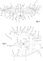
- Figure 5 shows a front elevational view of the aircraft 1. Please refer to the description of Figure 1 for details and definition of reference numerals.
- Figure 5 illustrates the fact that front wing 3 is inclined in an upward (positive z) direction from its contact (attachment) region with fuselage 2 towards its outer tips 3a.
- front wing 3 may level off so that it becomes parallel with (upper) aft wing 4a.
- the propellers 6b on each side are located at different heights (larger z values from front to rear) for reduced interference.
- Side connecting beams 5a, 5b have decreased distance between them towards the rear of the aircraft 1.
- Vertical stabilizers 8a, 8b are inclined outwardly w.r.t.
- the vertical stabilizers 8a, 8b are essentially parallel to each other on respective sides of the aircraft 1.
- Upper aft wing 4a and lower aft wing 4b are essentially straight, with upper aft wing 4a being longer than lower aft wing 4b.
- the latter is attached directly to fuselage 2, while the former is attached indirectly to fuselage 2 via the vertical stabilizers 8a, 8b.
- Propellers 9b are arranged on respective sides of the fuselage 2, so that there is no geometrical overlap along roll axis RA.
- Figure 6 shows a plan view of the aircraft 1. Please refer to the description of Figure 1 for details and definition of reference numerals.
- Figure 6 nicely illustrates the fact that the front wing 3 has a forward sweep apart from its tips 3a, which are angled backwards, i.e., towards the rear of the aircraft 1.
- Upper aft wing 4a and lower aft wing 4b, respectively, have a straight configuration - at least in a region of their respective front edges. Their respective rear edges may be curved, as shown.
- Lower aft wing 4b may extend further towards the rear of the aircraft 1 than upper aft wing 4a.
- front wing 3 may have a recess 3b with circular contour, which contour corresponds to an outer contour of an area swept by adjacent propeller 6b'. This feature may further reduce interference and increase lift, since front wing 3 is not blocking any downward airstream generated by propeller 6b'.
- a distance between a propeller axis of said propeller 6b' and the front wing 3 at least corresponds to a half of the diameter d' of the corresponding propeller 6b'. This is true at least for the frontmost propellers 6b as well.
- connection beams 5 owing to the proposed aircraft design, especially the proposed configuration of the connection beams 5, virtually no part of the aircraft structure is located below a propeller 6b, thus reducing blocking effects to a maximum.
- the connecting beams 5a, 5b may have an aerodynamic shape or outer contour for further reducing blocking effects.
- Figure 7 shows a further perspective view of the aircraft 1, as seen from the rear. Please refer to the description of Figure 1 for details and definition of reference numerals. In particular, Figure 7 discloses further details of the landing gear 7 toward the rear of the aircraft 1 and shows additional fin structures 10 below lower aft wing 4b.
- Figure 8 illustrates that rotor diameters of the vertically oriented propellers 6b are about 25% of an overall dimension, D, of the aircraft 1, wherein D is the diameter of an imaginary circle laid around the aircraft 1, when looking along a yaw axis thereof.
- the propellers 6b should be as large as possible, without interfering with other parts of the aircraft structure, in particular in terms of blocking.
- the two frontmost and the two aftmost propellers 6b could have a larger diameter than the middle propellers 6b'.
- the direction of rotation of the lifting propellers 6b can be chosen so that the front propellers 6b (leftmost, e.g., in figure 8 ) run from "outside to inside", because this first row of propellers 6b is most efficient for creating lift (due to a lack of interference). Furthermore, a quadrant in which the lift is created is located on the outside, i.e. further away from the CoG, and therefore requires less force for position control.
Claims (13)
- Aéronef (1) à décollage et atterrissage verticaux, comprenant :un fuselage (2) pour le transport de passagers et/ou de fret ;une aile avant (3) fixée au fuselage (2) ;une aile arrière (4) fixée au fuselage (2), derrière l'aile avant (3) dans une direction de vol vers l'avant (FF) ;un longeron de liaison droit (5a) et un longeron de liaison gauche (5b), lesquels longerons de liaison (5a, 5b) relient structurellement l'aile avant (3) et l'aile arrière (4), lesquels longerons de liaison (5a, 5b) sont espacés du fuselage (2) ; etau moins trois unités de propulsion (6) sur chacun des longerons de liaison (5a, 5b), lesquelles unités de propulsion (6) comprennent au moins une hélice (6b, 6b') et au moins un moteur (6a) entraînant ladite hélice (6b, 6b'), de préférence un moteur électrique, et sont agencées avec leur axe d'hélice respectif dans une orientation verticale (z) ;les au moins trois unités de propulsion (6) étant agencées les unes derrière les autres dans la direction de vol vers l'avant (FF) à différentes hauteurs (z), dans lequel parmi lesdites au moins trois unités de propulsion (6), une unité de propulsion (6) située davantage vers un arrière de l'aéronef (1) est située plus haut dans une direction le long de l'axe (z) vertical ou de lacet de l'aéronef (1) ;caractérisé en ce queles hélices (6b) sur chaque côté sont situées à différentes hauteurs (z), dans lequel une hauteur (z) respective augmente de l'avant à l'arrière le long de l'axe (z) vertical ou de lacet de l'aéronef (1).
- Aéronef (1) selon la revendication 1,
dans lequel les longerons de liaison (5a, 5b) s'étendent dans la direction de vol vers l'avant (FF) au-delà de l'aile avant (3), et au moins l'une des unités de propulsion (6) sur chaque côté est située sur un longeron de liaison (5a, 5b) respectif devant l'aile avant (3) dans la direction de vol vers l'avant (FF) ; et/ou les longerons de liaison (5a, 5b) s'étendent au-delà de l'aile arrière (4) dans une direction vers l'arrière, et au moins l'une des unités de propulsion (6) sur chaque côté est située sur un longeron de liaison (5a, 5b) respectif derrière l'aile arrière (4). - Aéronef (1) selon la revendication 1 ou 2,
dans lequel l'aile arrière (4) est conçue comme une aile en anneau, comprenant une aile arrière supérieure (4a) et une aile arrière inférieure (4b), lesquelles ailes arrière supérieure et inférieure (4a, 4b) sont agencées à distance l'une de l'autre dans une direction le long d'un axe (z) vertical ou de lacet de l'aéronef (1) et sont structurellement reliées par au moins un stabilisateur vertical externe (8) situé aux extrémités correspondantes de l'aile arrière supérieure (4a) et de l'aile arrière inférieure (4b), respectivement. - Aéronef (1) selon la revendication 3,
dans lequel l'aile arrière inférieure (4b) est mécaniquement et de préférence directement reliée à une partie arrière, dans la direction de vol vers l'avant (FF), du fuselage (2), et l'aile arrière supérieure (4a) est reliée à la partie arrière du fuselage (2) via au moins un stabilisateur vertical interne, de préférence deux stabilisateurs verticaux internes (8a). - Aéronef (1) selon la revendication 3 ou 4,
dans lequel l'aile arrière inférieure (4b) est symétrique en section transversale, avec moins d'inclinaison de profil aérodynamique par rapport à la direction de vol vers l'avant (FF) que l'aile avant (3) et l'aile arrière supérieure (4a). - Aéronef (1) selon l'une des revendications 1 à 5,
dans lequel, en plus des unités de propulsion orientées verticalement (6), de préférence devant un bord d'attaque de l'aile arrière (4), en particulier l'aile arrière inférieure (4b) lorsque prise en dépendance de la revendication 3, au moins une unité de propulsion orientée horizontalement (9) est présente, agencée à l'arrière du fuselage (2) dans la direction de vol vers l'avant (FF), de préférence deux unités de propulsion orientées horizontalement (9) situées sur le côté droit et le côté gauche du fuselage (2), respectivement, dans lequel un axe d'hélice respectif de ladite au moins une unité de propulsion orientée horizontalement (9) est orienté dans la direction de l'axe de roulis (RA) de l'aéronef. - Aéronef (1) selon la revendication 6,
dans lequel un diamètre (d) de l'hélice (9b) de l'au moins une unité de propulsion orientée horizontalement (9) est dimensionné pour être plus petit que les hélices (6b) des unités de propulsion orientées verticalement (6), de préférence ayant environ 20 % à 80 %, de manière préférée entre toutes environ 40 % à 60 %, d'un diamètre (d') des hélices (6b) des unités de propulsion orientées verticalement (6). - Aéronef (1) selon l'une des revendications 1 à 7,
dans lequel les longerons de liaison (5a, 5b) s'étendent parallèlement à la direction de vol vers l'avant (FF). - Aéronef (1) selon l'une des revendications 1 à 8,
dans lequel une distance entre les longerons de liaison (5a, 5b) diminue au moins dans une direction vers un arrière de l'aéronef (1) dans la direction de vol vers l'avant (FF). - Aéronef (1) selon l'une des revendications 1 à 9,
dans lequel, dans la direction de vol vers l'avant (FF) ou à l'opposé de celle-ci, une distance entre un axe d'hélice des unités de propulsion orientées verticalement (6) et l'une des ailes avant (3) et arrière (4) correspond à au moins un rayon de l'hélice (6b, 6b') correspondante. - Aéronef (1) selon l'une des revendications 1 à 10,
dans lequel le centre de gravité (CoG) de l'aéronef (1) est situé entre l'aile avant (3) et l'aile arrière (4) par rapport à la direction de vol vers l'avant (FF), et dans lequel de préférence un centre de portance (LC) de l'aéronef (1) est situé à l'arrière du centre de gravité (CoG) par rapport à la direction de vol vers l'avant (FF). - Aéronef (1) selon l'une des revendications 1 à 11,
dans lequel les diamètres de rotor des hélices (6b, 6b') orientées verticalement sont entre 10 % < D < 35 % d'une dimension globale, D, de l'aéronef (1), dans lequel D est le diamètre d'un cercle imaginaire placé autour de l'aéronef (1), lorsqu'on l'observe le long d'un axe (z) de lacet de celui-ci. - Aéronef (1) selon l'une des revendications 1 à 12,
dans lequel l'hélice (6b) la plus en avant et la plus en arrière, respectivement, sur chacun des longerons de liaison (5a, 5b) possède un plus grand diamètre que l'hélice médiane ou les hélices médianes (6b') .
Priority Applications (3)
| Application Number | Priority Date | Filing Date | Title |
|---|---|---|---|
| EP19182947.2A EP3757004B1 (fr) | 2019-06-27 | 2019-06-27 | Aéronef vtol avec des poutres de connexion d'ailes |
| US16/887,071 US11708158B2 (en) | 2019-06-27 | 2020-05-29 | Aircraft with right and left propulsion unit support beams extending between main and aft wings |
| CN202010575006.7A CN112141328B (zh) | 2019-06-27 | 2020-06-22 | 飞机 |
Applications Claiming Priority (1)
| Application Number | Priority Date | Filing Date | Title |
|---|---|---|---|
| EP19182947.2A EP3757004B1 (fr) | 2019-06-27 | 2019-06-27 | Aéronef vtol avec des poutres de connexion d'ailes |
Publications (2)
| Publication Number | Publication Date |
|---|---|
| EP3757004A1 EP3757004A1 (fr) | 2020-12-30 |
| EP3757004B1 true EP3757004B1 (fr) | 2023-03-29 |
Family
ID=67105910
Family Applications (1)
| Application Number | Title | Priority Date | Filing Date |
|---|---|---|---|
| EP19182947.2A Active EP3757004B1 (fr) | 2019-06-27 | 2019-06-27 | Aéronef vtol avec des poutres de connexion d'ailes |
Country Status (3)
| Country | Link |
|---|---|
| US (1) | US11708158B2 (fr) |
| EP (1) | EP3757004B1 (fr) |
| CN (1) | CN112141328B (fr) |
Families Citing this family (11)
| Publication number | Priority date | Publication date | Assignee | Title |
|---|---|---|---|---|
| FR3086641B1 (fr) * | 2018-09-28 | 2020-09-04 | Airbus Helicopters | Aeronef multirotor a motorisation electrique ou hybride avec une consommation energetique optimisee |
| DE102018133171A1 (de) * | 2018-12-20 | 2020-06-25 | Universität Stuttgart | Fluggerät |
| AU2020280074A1 (en) | 2019-05-21 | 2022-01-06 | Joby Aero, Inc. | Vtol aircraft using fixed forward canted rotors to simulate rigid wing dynamics |
| CA3073260A1 (fr) * | 2020-02-06 | 2021-08-06 | Chung-Kiak Poh | Avion a roto-stabilisateurs en tandem |
| EP3889727B1 (fr) | 2020-03-30 | 2024-04-03 | Volocopter GmbH | Procédé de commande d'un aéronef, dispositif de commande de vol pour un aéronef et aéronef comportant un tel dispositif de commande de vol |
| CN213974457U (zh) * | 2020-08-07 | 2021-08-17 | 上海峰飞航空科技有限公司 | 垂直起降空中无人机 |
| EP4056471A1 (fr) | 2021-03-08 | 2022-09-14 | Volocopter GmbH | Aéronef adav |
| JP2022151924A (ja) * | 2021-03-29 | 2022-10-12 | 本田技研工業株式会社 | 航空機 |
| US11760474B2 (en) * | 2021-06-06 | 2023-09-19 | Xi Wang | VTOL box-wing multirotor aerial vehicle |
| CN114180049B (zh) * | 2021-10-22 | 2024-02-02 | 上海新云彩航空科技有限责任公司 | 一种盒型复合翼飞行器 |
| EP4318166A1 (fr) | 2022-08-05 | 2024-02-07 | Volocopter GmbH | Procédé de commande d'un aéronef de transition et aéronef de transition |
Family Cites Families (32)
| Publication number | Priority date | Publication date | Assignee | Title |
|---|---|---|---|---|
| US3834654A (en) | 1973-03-19 | 1974-09-10 | Lockheed Aircraft Corp | Boxplane wing and aircraft |
| USD311720S (en) | 1988-11-14 | 1990-10-30 | Butler Gerald L | Aircraft |
| CA2141481A1 (fr) * | 1995-01-31 | 1996-08-01 | Youri Ouvarov | Aeronef avec rotor "s"/pales "c" repliables en voiture "o" |
| US5823468A (en) * | 1995-10-24 | 1998-10-20 | Bothe; Hans-Jurgen | Hybrid aircraft |
| DE19745492B4 (de) * | 1997-10-15 | 2005-06-09 | Wobben, Aloys, Dipl.-Ing. | Senkrecht startendes Flugzeug |
| US7159817B2 (en) * | 2005-01-13 | 2007-01-09 | Vandermey Timothy | Vertical take-off and landing (VTOL) aircraft with distributed thrust and control |
| JP2010023820A (ja) * | 2008-07-22 | 2010-02-04 | Keiichi Aoyanagi | 垂直離着陸する飛行機 |
| US8690096B2 (en) * | 2009-06-04 | 2014-04-08 | Alberto Alvarez-Calderon F. | Aircraft with dual flight regimes |
| FR2952612B1 (fr) * | 2009-11-17 | 2012-01-13 | Eurocopter France | Aeronef a grande distance franchissable et a vitesse d'avancement elevee en vol de croisiere |
| US9120560B1 (en) * | 2011-10-13 | 2015-09-01 | Latitude Engineering, LLC | Vertical take-off and landing aircraft |
| US9499266B1 (en) | 2014-06-24 | 2016-11-22 | Elytron Aircraft LLC | Five-wing aircraft to permit smooth transitions between vertical and horizontal flight |
| DE102014119273A1 (de) * | 2014-12-19 | 2016-06-23 | Christoph Fraundorfer | Tragschrauber mit einer stromlinienförmigen Außenkontur |
| DE102015001704B4 (de) * | 2015-02-13 | 2017-04-13 | Airbus Defence and Space GmbH | Senkrechtstartfähiges Fluggerät |
| CN105059535A (zh) * | 2015-09-14 | 2015-11-18 | 江富余 | 重力配平垂直升降飞机 |
| CN105217026B (zh) * | 2015-10-30 | 2017-12-19 | 佛山市神风航空科技有限公司 | 一种复合型飞行器 |
| CN106043685B (zh) * | 2016-01-27 | 2018-09-11 | 北京航空航天大学 | 双矢量推进桨旋翼/固定翼复合式垂直起降飞行器 |
| CN205327411U (zh) * | 2016-01-29 | 2016-06-22 | 成都纵横自动化技术有限公司 | 一种复合翼飞行器 |
| CN106218887A (zh) * | 2016-08-22 | 2016-12-14 | 杭州迅蚁网络科技有限公司 | 一种分布式动力装置布局的垂直起降飞行器 |
| US9764833B1 (en) | 2016-10-18 | 2017-09-19 | Kitty Hawk Corporation | Ventilated rotor mounting boom for personal aircraft |
| US10384776B2 (en) * | 2017-02-22 | 2019-08-20 | Bell Helicopter Textron Inc. | Tiltrotor aircraft having vertical lift and hover augmentation |
| CN106828915B (zh) * | 2017-03-15 | 2023-02-28 | 西北工业大学 | 一种倾转螺旋桨可垂直起降的高速飞行器的控制方法 |
| US10081436B1 (en) * | 2017-07-06 | 2018-09-25 | Autoflightx International Limited | Hybrid VTOL fixed-wing drone |
| US20190009899A1 (en) * | 2017-07-06 | 2019-01-10 | Autoflightx International Limited | Hybrid vtol fixed-wing drone having wing-tip propellers |
| CN107745809B (zh) * | 2017-10-14 | 2020-04-21 | 上海歌尔泰克机器人有限公司 | 飞行器 |
| CA3080204A1 (fr) * | 2017-10-27 | 2019-05-02 | Elroy Air, Inc. | Aeronef multicoptere composite |
| US10472064B2 (en) * | 2018-01-29 | 2019-11-12 | Yu Tian | VTOL fixed-wing aerial drone with interchangeable cabins |
| US10472058B2 (en) * | 2018-01-29 | 2019-11-12 | Shanghai Autoflight Co., Ltd. | VTOL aircraft with step-up overlapping propellers |
| US20190233077A1 (en) * | 2018-01-29 | 2019-08-01 | Yu Tian | Vtol fixed-wing flying platform system |
| US11267570B2 (en) * | 2018-05-03 | 2022-03-08 | Joby Aero, Inc. | Quad-wing vertical takeoff and landing aircraft |
| US10322814B1 (en) * | 2018-09-01 | 2019-06-18 | Autoflightx International Limited | Aircraft vertical stabilizer having a lift propeller and the method of using the same |
| IL263301B2 (en) * | 2018-11-25 | 2023-09-01 | Israel Aerospace Ind Ltd | Aircraft and the method of operation of aircraft |
| US20210362866A1 (en) * | 2019-02-20 | 2021-11-25 | Shanghai Autoflight Co., Ltd. | Unmanned Aerial Vehicle Power System for Minimizing Propulsion Failure |
-
2019
- 2019-06-27 EP EP19182947.2A patent/EP3757004B1/fr active Active
-
2020
- 2020-05-29 US US16/887,071 patent/US11708158B2/en active Active
- 2020-06-22 CN CN202010575006.7A patent/CN112141328B/zh active Active
Also Published As
| Publication number | Publication date |
|---|---|
| EP3757004A1 (fr) | 2020-12-30 |
| US11708158B2 (en) | 2023-07-25 |
| CN112141328B (zh) | 2023-11-24 |
| CN112141328A (zh) | 2020-12-29 |
| US20200407055A1 (en) | 2020-12-31 |
Similar Documents
| Publication | Publication Date | Title |
|---|---|---|
| EP3757004B1 (fr) | Aéronef vtol avec des poutres de connexion d'ailes | |
| KR102471407B1 (ko) | 강성 날개의 역학을 시뮬레이션하기 위해 회전자를 사용하는 vtol 항공기 | |
| US10144503B1 (en) | Fixed wing aircraft with trailing rotors | |
| US11634218B2 (en) | Redundant drive train for pylon mounted rotors | |
| JP6196795B2 (ja) | 性能向上型ウイングレットシステムおよびその方法 | |
| US8690096B2 (en) | Aircraft with dual flight regimes | |
| US11738863B2 (en) | Fixed wing aircraft with trailing rotors and T-tail | |
| JP2023512851A (ja) | 固定前方傾斜ロータを使用して剛体翼の空気力学をシミュレートする垂直離着陸航空機 | |
| EP3670341A1 (fr) | Aéronef à décollage et à atterrissage verticaux (adav) | |
| US20220281593A1 (en) | Vtol aircraft | |
| JP6784391B2 (ja) | コンパウンドヘリコプタ | |
| JP2015180563A (ja) | 垂直離着陸飛行体 | |
| CN106828911A (zh) | 串翼无人机 | |
| JP5791033B2 (ja) | 垂直離着陸飛行体 | |
| EP3401212B1 (fr) | Conception de stabilisateur vertical d'un aéronef | |
| JP2015180564A (ja) | 垂直離着陸飛行体 | |
| JP7012227B1 (ja) | 飛行体 | |
| CN111591440A (zh) | 一种镰刀翼垂直起降飞机 | |
| EP4008628B1 (fr) | Girodyne à ailes contreventées et en configuration à ailes jointes | |
| CN113264181B (zh) | 无尾复合式直升机 | |
| CN214875553U (zh) | 一种分布式推进的纵列式高速无人直升机 | |
| KR20230002357A (ko) | 헬리콥터, 헬리콥터 키트, 및 관련 재구성 방법 | |
| KR20230120915A (ko) | 비행체 |
Legal Events
| Date | Code | Title | Description |
|---|---|---|---|
| PUAI | Public reference made under article 153(3) epc to a published international application that has entered the european phase |
Free format text: ORIGINAL CODE: 0009012 |
|
| STAA | Information on the status of an ep patent application or granted ep patent |
Free format text: STATUS: THE APPLICATION HAS BEEN PUBLISHED |
|
| AK | Designated contracting states |
Kind code of ref document: A1 Designated state(s): AL AT BE BG CH CY CZ DE DK EE ES FI FR GB GR HR HU IE IS IT LI LT LU LV MC MK MT NL NO PL PT RO RS SE SI SK SM TR |
|
| AX | Request for extension of the european patent |
Extension state: BA ME |
|
| STAA | Information on the status of an ep patent application or granted ep patent |
Free format text: STATUS: REQUEST FOR EXAMINATION WAS MADE |
|
| 17P | Request for examination filed |
Effective date: 20210525 |
|
| RBV | Designated contracting states (corrected) |
Designated state(s): AL AT BE BG CH CY CZ DE DK EE ES FI FR GB GR HR HU IE IS IT LI LT LU LV MC MK MT NL NO PL PT RO RS SE SI SK SM TR |
|
| STAA | Information on the status of an ep patent application or granted ep patent |
Free format text: STATUS: EXAMINATION IS IN PROGRESS |
|
| 17Q | First examination report despatched |
Effective date: 20211014 |
|
| GRAP | Despatch of communication of intention to grant a patent |
Free format text: ORIGINAL CODE: EPIDOSNIGR1 |
|
| STAA | Information on the status of an ep patent application or granted ep patent |
Free format text: STATUS: GRANT OF PATENT IS INTENDED |
|
| RIC1 | Information provided on ipc code assigned before grant |
Ipc: B64C 39/00 20060101ALN20221114BHEP Ipc: B64C 39/02 20060101ALN20221114BHEP Ipc: B64C 27/08 20060101ALN20221114BHEP Ipc: B64C 27/20 20060101ALN20221114BHEP Ipc: B64C 39/06 20060101ALI20221114BHEP Ipc: B64C 39/08 20060101ALI20221114BHEP Ipc: B64C 29/00 20060101AFI20221114BHEP |
|
| INTG | Intention to grant announced |
Effective date: 20221219 |
|
| GRAS | Grant fee paid |
Free format text: ORIGINAL CODE: EPIDOSNIGR3 |
|
| GRAA | (expected) grant |
Free format text: ORIGINAL CODE: 0009210 |
|
| STAA | Information on the status of an ep patent application or granted ep patent |
Free format text: STATUS: THE PATENT HAS BEEN GRANTED |
|
| AK | Designated contracting states |
Kind code of ref document: B1 Designated state(s): AL AT BE BG CH CY CZ DE DK EE ES FI FR GB GR HR HU IE IS IT LI LT LU LV MC MK MT NL NO PL PT RO RS SE SI SK SM TR |
|
| REG | Reference to a national code |
Ref country code: CH Ref legal event code: EP |
|
| REG | Reference to a national code |
Ref country code: DE Ref legal event code: R096 Ref document number: 602019026810 Country of ref document: DE |
|
| REG | Reference to a national code |
Ref country code: AT Ref legal event code: REF Ref document number: 1556509 Country of ref document: AT Kind code of ref document: T Effective date: 20230415 |
|
| REG | Reference to a national code |
Ref country code: IE Ref legal event code: FG4D |
|
| P01 | Opt-out of the competence of the unified patent court (upc) registered |
Effective date: 20230517 |
|
| REG | Reference to a national code |
Ref country code: LT Ref legal event code: MG9D |
|
| PG25 | Lapsed in a contracting state [announced via postgrant information from national office to epo] |
Ref country code: RS Free format text: LAPSE BECAUSE OF FAILURE TO SUBMIT A TRANSLATION OF THE DESCRIPTION OR TO PAY THE FEE WITHIN THE PRESCRIBED TIME-LIMIT Effective date: 20230329 Ref country code: NO Free format text: LAPSE BECAUSE OF FAILURE TO SUBMIT A TRANSLATION OF THE DESCRIPTION OR TO PAY THE FEE WITHIN THE PRESCRIBED TIME-LIMIT Effective date: 20230629 Ref country code: LV Free format text: LAPSE BECAUSE OF FAILURE TO SUBMIT A TRANSLATION OF THE DESCRIPTION OR TO PAY THE FEE WITHIN THE PRESCRIBED TIME-LIMIT Effective date: 20230329 Ref country code: LT Free format text: LAPSE BECAUSE OF FAILURE TO SUBMIT A TRANSLATION OF THE DESCRIPTION OR TO PAY THE FEE WITHIN THE PRESCRIBED TIME-LIMIT Effective date: 20230329 Ref country code: HR Free format text: LAPSE BECAUSE OF FAILURE TO SUBMIT A TRANSLATION OF THE DESCRIPTION OR TO PAY THE FEE WITHIN THE PRESCRIBED TIME-LIMIT Effective date: 20230329 |
|
| PGFP | Annual fee paid to national office [announced via postgrant information from national office to epo] |
Ref country code: FR Payment date: 20230630 Year of fee payment: 5 Ref country code: DE Payment date: 20230623 Year of fee payment: 5 |
|
| REG | Reference to a national code |
Ref country code: NL Ref legal event code: MP Effective date: 20230329 |
|
| REG | Reference to a national code |
Ref country code: AT Ref legal event code: MK05 Ref document number: 1556509 Country of ref document: AT Kind code of ref document: T Effective date: 20230329 |
|
| PG25 | Lapsed in a contracting state [announced via postgrant information from national office to epo] |
Ref country code: SE Free format text: LAPSE BECAUSE OF FAILURE TO SUBMIT A TRANSLATION OF THE DESCRIPTION OR TO PAY THE FEE WITHIN THE PRESCRIBED TIME-LIMIT Effective date: 20230329 Ref country code: NL Free format text: LAPSE BECAUSE OF FAILURE TO SUBMIT A TRANSLATION OF THE DESCRIPTION OR TO PAY THE FEE WITHIN THE PRESCRIBED TIME-LIMIT Effective date: 20230329 Ref country code: GR Free format text: LAPSE BECAUSE OF FAILURE TO SUBMIT A TRANSLATION OF THE DESCRIPTION OR TO PAY THE FEE WITHIN THE PRESCRIBED TIME-LIMIT Effective date: 20230630 Ref country code: FI Free format text: LAPSE BECAUSE OF FAILURE TO SUBMIT A TRANSLATION OF THE DESCRIPTION OR TO PAY THE FEE WITHIN THE PRESCRIBED TIME-LIMIT Effective date: 20230329 |
|
| PG25 | Lapsed in a contracting state [announced via postgrant information from national office to epo] |
Ref country code: SM Free format text: LAPSE BECAUSE OF FAILURE TO SUBMIT A TRANSLATION OF THE DESCRIPTION OR TO PAY THE FEE WITHIN THE PRESCRIBED TIME-LIMIT Effective date: 20230329 Ref country code: RO Free format text: LAPSE BECAUSE OF FAILURE TO SUBMIT A TRANSLATION OF THE DESCRIPTION OR TO PAY THE FEE WITHIN THE PRESCRIBED TIME-LIMIT Effective date: 20230329 Ref country code: PT Free format text: LAPSE BECAUSE OF FAILURE TO SUBMIT A TRANSLATION OF THE DESCRIPTION OR TO PAY THE FEE WITHIN THE PRESCRIBED TIME-LIMIT Effective date: 20230731 Ref country code: ES Free format text: LAPSE BECAUSE OF FAILURE TO SUBMIT A TRANSLATION OF THE DESCRIPTION OR TO PAY THE FEE WITHIN THE PRESCRIBED TIME-LIMIT Effective date: 20230329 Ref country code: EE Free format text: LAPSE BECAUSE OF FAILURE TO SUBMIT A TRANSLATION OF THE DESCRIPTION OR TO PAY THE FEE WITHIN THE PRESCRIBED TIME-LIMIT Effective date: 20230329 Ref country code: AT Free format text: LAPSE BECAUSE OF FAILURE TO SUBMIT A TRANSLATION OF THE DESCRIPTION OR TO PAY THE FEE WITHIN THE PRESCRIBED TIME-LIMIT Effective date: 20230329 |
|
| PGFP | Annual fee paid to national office [announced via postgrant information from national office to epo] |
Ref country code: GB Payment date: 20230724 Year of fee payment: 5 |
|
| PG25 | Lapsed in a contracting state [announced via postgrant information from national office to epo] |
Ref country code: SK Free format text: LAPSE BECAUSE OF FAILURE TO SUBMIT A TRANSLATION OF THE DESCRIPTION OR TO PAY THE FEE WITHIN THE PRESCRIBED TIME-LIMIT Effective date: 20230329 Ref country code: PL Free format text: LAPSE BECAUSE OF FAILURE TO SUBMIT A TRANSLATION OF THE DESCRIPTION OR TO PAY THE FEE WITHIN THE PRESCRIBED TIME-LIMIT Effective date: 20230329 Ref country code: IS Free format text: LAPSE BECAUSE OF FAILURE TO SUBMIT A TRANSLATION OF THE DESCRIPTION OR TO PAY THE FEE WITHIN THE PRESCRIBED TIME-LIMIT Effective date: 20230729 |
|
| REG | Reference to a national code |
Ref country code: DE Ref legal event code: R097 Ref document number: 602019026810 Country of ref document: DE |
|
| PG25 | Lapsed in a contracting state [announced via postgrant information from national office to epo] |
Ref country code: MC Free format text: LAPSE BECAUSE OF FAILURE TO SUBMIT A TRANSLATION OF THE DESCRIPTION OR TO PAY THE FEE WITHIN THE PRESCRIBED TIME-LIMIT Effective date: 20230329 |
|
| REG | Reference to a national code |
Ref country code: DE Ref legal event code: R081 Ref document number: 602019026810 Country of ref document: DE Owner name: VOLOCOPTER GMBH, DE Free format text: FORMER OWNER: VOLOCOPTER GMBH, 76646 BRUCHSAL, DE |
|
| RAP4 | Party data changed (patent owner data changed or rights of a patent transferred) |
Owner name: VOLOCOPTER GMBH |
|
| PG25 | Lapsed in a contracting state [announced via postgrant information from national office to epo] |
Ref country code: MC Free format text: LAPSE BECAUSE OF FAILURE TO SUBMIT A TRANSLATION OF THE DESCRIPTION OR TO PAY THE FEE WITHIN THE PRESCRIBED TIME-LIMIT Effective date: 20230329 Ref country code: DK Free format text: LAPSE BECAUSE OF FAILURE TO SUBMIT A TRANSLATION OF THE DESCRIPTION OR TO PAY THE FEE WITHIN THE PRESCRIBED TIME-LIMIT Effective date: 20230329 Ref country code: CZ Free format text: LAPSE BECAUSE OF FAILURE TO SUBMIT A TRANSLATION OF THE DESCRIPTION OR TO PAY THE FEE WITHIN THE PRESCRIBED TIME-LIMIT Effective date: 20230329 |
|
| REG | Reference to a national code |
Ref country code: CH Ref legal event code: PL |
|
| PLBE | No opposition filed within time limit |
Free format text: ORIGINAL CODE: 0009261 |
|
| STAA | Information on the status of an ep patent application or granted ep patent |
Free format text: STATUS: NO OPPOSITION FILED WITHIN TIME LIMIT |
|
| REG | Reference to a national code |
Ref country code: BE Ref legal event code: MM Effective date: 20230630 |
|
| PG25 | Lapsed in a contracting state [announced via postgrant information from national office to epo] |
Ref country code: LU Free format text: LAPSE BECAUSE OF NON-PAYMENT OF DUE FEES Effective date: 20230627 |
|
| 26N | No opposition filed |
Effective date: 20240103 |
|
| REG | Reference to a national code |
Ref country code: IE Ref legal event code: MM4A |
|
| PG25 | Lapsed in a contracting state [announced via postgrant information from national office to epo] |
Ref country code: LU Free format text: LAPSE BECAUSE OF NON-PAYMENT OF DUE FEES Effective date: 20230627 |