EP3756981B1 - Active spoiler structure capable of opening by rotation - Google Patents
Active spoiler structure capable of opening by rotation Download PDFInfo
- Publication number
- EP3756981B1 EP3756981B1 EP19219686.3A EP19219686A EP3756981B1 EP 3756981 B1 EP3756981 B1 EP 3756981B1 EP 19219686 A EP19219686 A EP 19219686A EP 3756981 B1 EP3756981 B1 EP 3756981B1
- Authority
- EP
- European Patent Office
- Prior art keywords
- spoiler
- gear rack
- rocker
- lug
- active
- Prior art date
- Legal status (The legal status is an assumption and is not a legal conclusion. Google has not performed a legal analysis and makes no representation as to the accuracy of the status listed.)
- Active
Links
Images


Classifications
-
- B—PERFORMING OPERATIONS; TRANSPORTING
- B62—LAND VEHICLES FOR TRAVELLING OTHERWISE THAN ON RAILS
- B62D—MOTOR VEHICLES; TRAILERS
- B62D35/00—Vehicle bodies characterised by streamlining
- B62D35/007—Rear spoilers
-
- B—PERFORMING OPERATIONS; TRANSPORTING
- B62—LAND VEHICLES FOR TRAVELLING OTHERWISE THAN ON RAILS
- B62D—MOTOR VEHICLES; TRAILERS
- B62D37/00—Stabilising vehicle bodies without controlling suspension arrangements
- B62D37/02—Stabilising vehicle bodies without controlling suspension arrangements by aerodynamic means
-
- Y—GENERAL TAGGING OF NEW TECHNOLOGICAL DEVELOPMENTS; GENERAL TAGGING OF CROSS-SECTIONAL TECHNOLOGIES SPANNING OVER SEVERAL SECTIONS OF THE IPC; TECHNICAL SUBJECTS COVERED BY FORMER USPC CROSS-REFERENCE ART COLLECTIONS [XRACs] AND DIGESTS
- Y02—TECHNOLOGIES OR APPLICATIONS FOR MITIGATION OR ADAPTATION AGAINST CLIMATE CHANGE
- Y02T—CLIMATE CHANGE MITIGATION TECHNOLOGIES RELATED TO TRANSPORTATION
- Y02T10/00—Road transport of goods or passengers
- Y02T10/80—Technologies aiming to reduce greenhouse gasses emissions common to all road transportation technologies
- Y02T10/82—Elements for improving aerodynamics
Definitions
- the present invention relates to the field of spoilers, and more specifically, to an active spoiler structure capable of opening by rotation.
- An objective of the present invention is to provide an active spoiler structure capable of opening by rotation, so as to resolve the problems of large assembly error and high processing accuracy requirements of the spoiler structure in the prior art.
- the active spoiler structure capable of opening by rotation.
- the active spoiler structure comprises:
- the sliding gear rack is fixed to the rocker rotating support at a location between the first lug and the second lug.
- the assisting rocker is provided with a position limiting structure providing the locking and immobilization function.
- the active spoiler structure is in an axisymmetric structure centered on the electric motor, wherein a same electric motor drives the left and right two gears to rotate and then drives the left and right two sliding gear racks to move, such that the opening or closing by rotation of the spoiler is realized in a synchronized manner.
- the sliding gear rack is in a L-shaped structure.
- the sliding gear rack is provided with saw teeth on one side.
- the gear rack fixing pressing plate is fixed to a fixing base by means of a fastening member.
- the spoiler is in an oblong sheet-shaped structure.
- the spoiler cooperates in form fitting with a vehicle tailgate in the closed position, and forms with the vehicle tailgate a passage for airflow between the spoiler and the vehicle tailgate in a opened position.
- the gear is driven to rotate by the rotation and force transmission of the electric motor, and in turn, transmits a force to drive the gear rack to move, thus driving the spoiler to open by rotation, changing the trend of airflow vortex during the course of driving a vehicle, and finally realizing the vortex away from the rear of the vehicle, thereby reducing the wind resistance.
- vehicle energy saving and emission reduction can be realized and the life of new energy batteries can be extended.
- the present invention provides an active spoiler structure that can effectively reduce the risk to safe driving caused by an excessive lifting force of a vehicle due to an excessive speed, and reduce energy consumption and increase the service life of energy batteries, thus realizing high speed safe driving, environmental protection, energy saving and emission reduction.
- an active spoiler structure capable of opening by rotation is provided according to a preferred embodiment of the present invention.
- a spoiler 1 in the active spoiler structure cooperates in form fitting with a vehicle tailgate 100 in a closed state, and does not have any effect on an assembled vehicle's wind resistance.
- the spoiler 1 in the active spoiler structure forms with the vehicle tailgate 100 a passage for air to flow through in between in a opened state, thus reducing air drag, achieving a reduction of vehicle energy consumption and emissions, increasing the life of service of new energy cells, and at the same time, increasing the downforce and overcoming the problem of unstable driving and insufficient safety.
- the active spoiler structure comprises: a spoiler 1 in an oblong sheet-shaped structure; a first lug 2 and a second lug 3 provided at the rear side of the spoiler 1; a rocker rotating support 4 mounted to the rear side of the spoiler 1 through the first lug 2 and the second lug 3; an assisting rocker 5 connected to the rocker rotating support 4 through the first lug 2, another end of the assisting rocker 5 being fixed to a gear rack fixing pressing plate 11, the assisting rocker 5 being provided with a position limiting structure providing a locking and immobilizing function, the gear rack fixing pressing plate 11 being fastened to a fixing base 6 through a bolt (or a screw); an electric motor 7 connected in signal to an electronic control unit (ECU); a rotary shaft 8 driven to rotate by the electric motor 7; a gear 9 that is sleeved at a terminal end of the rotary
- ECU electronice control unit
- the sliding gear rack 10 is positionally limited by the gear rack fixing pressing plate 11, so that it can only move back and forth in one plane under the driving of the gear 9.
- the active spoiler structure is an axisymmetric structure centered on the electric motor 7, simultaneously driving the left and right two gears 9 to rotate by the same electric motor 7, thereby driving the left and right two sliding gear racks 10 to move, and achieving in a synchronized manner the opening or closing by rotation of the spoiler 1.
- a vehicle speed sensor captures the speed of the vehicle, and sends a signal to the electronic control unit.
- the electronic control unit in turn sends a signal to the electric motor 7.
- the electric motor 7 drives the rotary shaft 8 to rotate, and thus drives the gears 9 to rotate.
- the sliding gear rack 10 engaging with the gear 9 moves in an oblique upward direction with the rotation of the gear; when the sliding gear racks 10 move upward to a predetermined position, the assisting rocker 5 will be locked and immobilized by the position limiting structure.
- the electric motor 7 continues to drive the sliding gear racks 10 to move upward; under the continuous pushing of the sliding gear racks 10, the rocker rotating support 4 is further turned upward around the joint between the rocker rotating support 4 and the first lug 2 as a center, so that the spoiler 1 rotates and opens to a certain angle, the angle being better when it reduces wind resistance and increases the aerodynamic downforce to the maximum, thus achieving the effect of reducing energy consumption and emissions and the assembled vehicle's high speed safe driving.
- the electric motor 7 further controls the angle of opening of the spoiler 1, achieving maximum reduction of wind resistance and increase of aerodynamic downforce.
- the electric motor rotates forward to control the above-described movement mechanism to realize the opening of the spoiler; while the electric motor rotates reversely to control the above-described movement mechanism to achieve the closing of the spoiler.
- the specific angle of opening of the spoiler 1 is an angle calculated by analysis and verification upon the vehicle wind-tunnel experimental tests.
Landscapes
- Engineering & Computer Science (AREA)
- Chemical & Material Sciences (AREA)
- Combustion & Propulsion (AREA)
- Transportation (AREA)
- Mechanical Engineering (AREA)
- Physics & Mathematics (AREA)
- Fluid Mechanics (AREA)
- Power-Operated Mechanisms For Wings (AREA)
Description
- The present invention relates to the field of spoilers, and more specifically, to an active spoiler structure capable of opening by rotation.
- Currently, to reduce wind resistance of an assembled vehicle, a measure generally adopted is to increase the aerodynamic downforce when the vehicle moves at a high speed. Specifically, a fixed spoiler that remains unchanged is employed, or a structure with four connecting rods that has relatively poor stability is employed to drive a spoiler to open and close. An example of such an active spoiler is given in
US 4756568 . - However, with this type of assembly form, the cumulative assembly error of a spoiler is significant, very high precision of machining of parts themselves is required, and the parts depend very much on the control of an electric motor with a large torque. Therefore, how to adapt to a speed change of a vehicle at a low cost but with a high efficiency by providing an active spoiler that can open and close according to different driving conditions so as to achieve reducing wind resistance and increasing the vehicle's aerodynamic downforce is a problem that urgently needs to be resolved.
- An objective of the present invention is to provide an active spoiler structure capable of opening by rotation, so as to resolve the problems of large assembly error and high processing accuracy requirements of the spoiler structure in the prior art.
- To resolve the above-mentioned technical problem, the present invention adopts the following technical solution:
An active spoiler structure capable of opening by rotation is provided. The active spoiler structure comprises: - a spoiler mounted at a tail of a vehicle and provided with a first lug and a second lug at its rear side;
- a rocker rotating support mounted to the rear side of the spoiler through the first lug and the second lug;
- an assisting rocker connected to the rocker rotating support through the first lug, another end of the assisting rocker being fixed to a gear rack fixing pressing plate;
- an electric motor connected in signal to an electronic control unit;
- a rotary shaft configured to be driven to rotate by the electric motor;
- a gear being sleeved at a terminal end of the rotary shaft and capable of rotating therewith; and,
- a sliding gear rack, one end of the sliding gear rack engaging with the gear and the other end of the sliding gear rack being connected to the rocker rotating support, the sliding gear rack being positionally limited by the gear rack fixing pressing plate;
- The sliding gear rack is fixed to the rocker rotating support at a location between the first lug and the second lug.
- The assisting rocker is provided with a position limiting structure providing the locking and immobilization function.
- When the assisting rocker is locked and immobilized by means of the position limiting structure, under the continuous pushing of the sliding gear rack, the rocker rotating support rotates around the joint between the rocker rotating support and the first lug as a center, thus driving the spoiler to rotate and open.
- The active spoiler structure is in an axisymmetric structure centered on the electric motor, wherein a same electric motor drives the left and right two gears to rotate and then drives the left and right two sliding gear racks to move, such that the opening or closing by rotation of the spoiler is realized in a synchronized manner.
- The sliding gear rack is in a L-shaped structure.
- The sliding gear rack is provided with saw teeth on one side.
- The gear rack fixing pressing plate is fixed to a fixing base by means of a fastening member.
- The spoiler is in an oblong sheet-shaped structure.
- The spoiler cooperates in form fitting with a vehicle tailgate in the closed position, and forms with the vehicle tailgate a passage for airflow between the spoiler and the vehicle tailgate in a opened position.
- According to the active spoiler structure provided by the present invention, the gear is driven to rotate by the rotation and force transmission of the electric motor, and in turn, transmits a force to drive the gear rack to move, thus driving the spoiler to open by rotation, changing the trend of airflow vortex during the course of driving a vehicle, and finally realizing the vortex away from the rear of the vehicle, thereby reducing the wind resistance. Thus, vehicle energy saving and emission reduction can be realized and the life of new energy batteries can be extended.
- In summary, the present invention provides an active spoiler structure that can effectively reduce the risk to safe driving caused by an excessive lifting force of a vehicle due to an excessive speed, and reduce energy consumption and increase the service life of energy batteries, thus realizing high speed safe driving, environmental protection, energy saving and emission reduction.
-
-
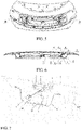
FIG. 1 is a schematic view of an active spoiler structure provided according to a preferred embodiment of the present invention, in a closed state on an assembled vehicle; -
FIG. 2 is a lateral view of the rear of the vehicle in the state shown inFIG. 1 ; -
FIG. 3 is a schematic view of an active spoiler structure provided according to a preferred embodiment of the present invention, in a opened state on an assembled vehicle; -
FIG. 4 is a lateral view of the rear of the vehicle in the state shown inFIG. 3 ; -
FIG. 5 is an overall assembled view of an active spoiler structure provided according to a preferred embodiment of the present invention on an assembled vehicle; -
FIG. 6 is a sectional view along the sectional line B-B inFIG. 5 ; -
FIG. 7 is an enlarged schematic view of a partial detail of the active spoiler structure. - The present invention is further described below with reference to specific embodiments. It should be understood that, the following embodiments are merely used to describe the present invention and not to limit the scope of the present invention.
- In reference to
FIG. 1 and FIG. 2 , an active spoiler structure capable of opening by rotation is provided according to a preferred embodiment of the present invention. Aspoiler 1 in the active spoiler structure cooperates in form fitting with avehicle tailgate 100 in a closed state, and does not have any effect on an assembled vehicle's wind resistance. - In reference to
FIG. 3 and FIG. 4 , thespoiler 1 in the active spoiler structure forms with the vehicle tailgate 100 a passage for air to flow through in between in a opened state, thus reducing air drag, achieving a reduction of vehicle energy consumption and emissions, increasing the life of service of new energy cells, and at the same time, increasing the downforce and overcoming the problem of unstable driving and insufficient safety. - Specifically, the active spoiler structure provided according to this preferred embodiment is as shown in
FIG. 5 to FIG. 7 , and is described in detail as follows:
The active spoiler structure comprises: aspoiler 1 in an oblong sheet-shaped structure; a first lug 2 and asecond lug 3 provided at the rear side of thespoiler 1; a rocker rotating support 4 mounted to the rear side of thespoiler 1 through the first lug 2 and thesecond lug 3; an assistingrocker 5 connected to the rocker rotating support 4 through the first lug 2, another end of the assistingrocker 5 being fixed to a gear rack fixing pressingplate 11, the assistingrocker 5 being provided with a position limiting structure providing a locking and immobilizing function, the gear rack fixing pressingplate 11 being fastened to afixing base 6 through a bolt (or a screw); anelectric motor 7 connected in signal to an electronic control unit (ECU); arotary shaft 8 driven to rotate by theelectric motor 7; agear 9 that is sleeved at a terminal end of therotary shaft 8 and rotatable with therotary shaft 8; and, asliding gear rack 10 of which one end engages with thegear 9 and another end is connected to the rocker rotating support 4, thesliding gear rack 10 being fixed to the rocker rotating support 4 at a location between the first lug 2 and thesecond lug 3, as shown inFIG. 7 , thesliding gear rack 10 being of an arc-shaped structure and provided with saw teeth on one side. - Preferably, the
sliding gear rack 10 is positionally limited by the gear rack fixing pressingplate 11, so that it can only move back and forth in one plane under the driving of thegear 9. - According to this preferred embodiment, the active spoiler structure is an axisymmetric structure centered on the
electric motor 7, simultaneously driving the left and right twogears 9 to rotate by the sameelectric motor 7, thereby driving the left and right two sliding gear racks 10 to move, and achieving in a synchronized manner the opening or closing by rotation of thespoiler 1. - The principle of operation of the active spoiler structure provided according to the above-described preferred embodiment is as follows:
A vehicle speed sensor captures the speed of the vehicle, and sends a signal to the electronic control unit. The electronic control unit in turn sends a signal to theelectric motor 7. Theelectric motor 7 drives therotary shaft 8 to rotate, and thus drives thegears 9 to rotate. Thesliding gear rack 10 engaging with thegear 9 moves in an oblique upward direction with the rotation of the gear; when the sliding gear racks 10 move upward to a predetermined position, the assistingrocker 5 will be locked and immobilized by the position limiting structure. Theelectric motor 7 continues to drive the sliding gear racks 10 to move upward; under the continuous pushing of the sliding gear racks 10, the rocker rotating support 4 is further turned upward around the joint between the rocker rotating support 4 and the first lug 2 as a center, so that thespoiler 1 rotates and opens to a certain angle, the angle being better when it reduces wind resistance and increases the aerodynamic downforce to the maximum, thus achieving the effect of reducing energy consumption and emissions and the assembled vehicle's high speed safe driving. - As the vehicle speed changes, under the control of the electronic control unit, the
electric motor 7 further controls the angle of opening of thespoiler 1, achieving maximum reduction of wind resistance and increase of aerodynamic downforce. - When the vehicle speed captured by the vehicle speed sensor slows down gradually to zero, a signal is sent to the electronic control unit, which in turn sends a signal to the
electric motor 7. Theelectric motor 7 drives therotary shaft 8 to rotate in the opposite direction. The sliding gear racks 10 engaging with thegears 9 move downward with the rotation of the gears. The rocker rotating support 4 thus rotates downward around the joint between the rocker rotating support 4 and the first lug 2 as the center. Subsequently, the assistingrocker 5 is unlocked. Theelectric motor 7 continues to rotate, driving the sliding gear racks 10 to move downward. Under the continuous pulling of the sliding gear racks 10, thespoiler 1 moves downward until cooperating in form fitting with thevehicle tailgate 100, ultimately achieving the closing of thespoiler 1. - According to a preferred embodiment of the present invention, the electric motor rotates forward to control the above-described movement mechanism to realize the opening of the spoiler; while the electric motor rotates reversely to control the above-described movement mechanism to achieve the closing of the spoiler.
- In the embodiment, the specific angle of opening of the
spoiler 1 is an angle calculated by analysis and verification upon the vehicle wind-tunnel experimental tests. - What has been described above are merely preferred embodiments of the present invention, and is not intended to limit the scope of the present invention. Various changes may be further made to the above-described embodiments of the present invention. The invention is defined by the claims only.
- Conventional technologies are not described in detail in the present invention.
Claims (10)
- An active spoiler structure capable of opening by rotation, characterized in that, the active spoiler structure comprises:- a spoiler (1) mounted at a tail of a vehicle and provided with a first lug (2) and a second lug (3) at its rear side;- a rocker rotating support (4) mounted to the rear side of the spoiler (1) through the first lug (2) and the second lug (3);- an assisting rocker (5) connected to the rocker rotating support (4) through the first lug (2), another end of the assisting rocker (5) being fixed to a gear rack fixing pressing plate (11);- an electric motor (7) connected in signal to an electronic control unit;- a rotary shaft (8) configured to be driven to rotate by the electric motor (7);- a gear (9) being sleeved at a terminal end of the rotary shaft (8) and capable of rotating therewith; and,- a sliding gear rack (10), one end of the sliding gear rack (10) engaging with the gear (9) and the other end of the sliding gear rack (10) being connected to the rocker rotating support (4), the sliding gear rack being positionally limited by the gear rack fixing pressing plate (11);wherein, according to a real time speed of the vehicle and under the control of the electronic control unit, the spoiler (1) can open by rotation from a closed position, and remains at an optimal angle that can minimize the wind resistance and maximize the aerodynamic downforce.
- The active spoiler structure according to claim 1, wherein the sliding gear rack (10) is fixed to the rocker rotating support (4) at a location between the first lug (2) and the second lug (3).
- The active spoiler structure according to any one of the previous claims, wherein the assisting rocker (5) is provided with a position limiting structure providing the locking and immobilization function.
- The active spoiler structure according to any one of the previous claims, wherein when the assisting rocker (5) is locked and immobilized by means of the position limiting structure, under a continuous pushing of the sliding gear rack (10), the rocker rotating support (4) rotates around the joint between the rocker rotating support (4) and the first lug (2) as a center, thus driving the spoiler (1) to rotate and open.
- The active spoiler structure according to any one of the previous claims, wherein the active spoiler structure is in an axisymmetric structure centered on the electric motor (7), wherein a same electric motor drives the left and right two gears (9) to rotate and then drives the left and right two sliding gear racks (10) to move, such that the opening or closing by rotation of the spoiler (1) is realized in a synchronized manner.
- The active spoiler structure according to any one of the previous claims , wherein the sliding gear rack (10) is in a L-shaped structure.
- The active spoiler structure according to any one of the previous claims, wherein the sliding gear rack (10) is provided with saw teeth on one side.
- The active spoiler structure according to any one of the previous claims, wherein the gear rack fixing pressing plate (11) is fixed to a fixing base (6) by means of a fastening member.
- The active spoiler structure according to any one of the previous claims, wherein the spoiler (1) is in an oblong sheet-shaped structure.
- The active spoiler structure according to any one of the previous claims, wherein the spoiler (1) cooperates in form fitting with a vehicle tailgate (100) in the closed position, and forms with the vehicle tailgate (100) a passage for airflow between the spoiler (1) and the vehicle tailgate (100) in a opened position.
Applications Claiming Priority (2)
| Application Number | Priority Date | Filing Date | Title |
|---|---|---|---|
| CN201921005259.XU CN210101804U (en) | 2019-06-28 | 2019-06-28 | A rotatable open active spoiler structure |
| CN201910583922.2A CN110228538B (en) | 2019-06-28 | 2019-06-28 | Active spoiler structure capable of being opened in rotating mode |
Publications (3)
| Publication Number | Publication Date |
|---|---|
| EP3756981A1 EP3756981A1 (en) | 2020-12-30 |
| EP3756981B1 true EP3756981B1 (en) | 2022-05-04 |
| EP3756981B8 EP3756981B8 (en) | 2022-12-28 |
Family
ID=84179628
Family Applications (1)
| Application Number | Title | Priority Date | Filing Date |
|---|---|---|---|
| EP19219686.3A Active EP3756981B8 (en) | 2019-06-28 | 2019-12-24 | Active spoiler structure capable of opening by rotation |
Country Status (1)
| Country | Link |
|---|---|
| EP (1) | EP3756981B8 (en) |
Families Citing this family (5)
| Publication number | Priority date | Publication date | Assignee | Title |
|---|---|---|---|---|
| CN114954703A (en) * | 2022-06-08 | 2022-08-30 | 上海集度汽车有限公司 | Fin structure and car |
| CN115056865A (en) * | 2022-06-20 | 2022-09-16 | 华人运通(江苏)技术有限公司 | Flow disturbing device for vehicle, control method, control device and vehicle |
| CN115092336B (en) * | 2022-07-11 | 2025-05-09 | 华能广东汕头海上风电有限责任公司 | A floating column spoiler structure, a floating column and a floating fan |
| CN116001926B (en) * | 2022-12-23 | 2025-09-26 | 蔚来汽车科技(安徽)有限公司 | Spoiler for vehicle and vehicle having the same |
| CN117163172B (en) * | 2023-10-18 | 2026-01-06 | 一汽解放汽车有限公司 | Carriage, vehicle and turbulence control methods |
Family Cites Families (4)
| Publication number | Priority date | Publication date | Assignee | Title |
|---|---|---|---|---|
| JPS62221955A (en) * | 1986-03-20 | 1987-09-30 | Mazda Motor Corp | Rear wiper enclosure for automobile |
| JPH068169U (en) * | 1992-07-03 | 1994-02-01 | 三菱自動車工業株式会社 | Spoiler device with deflector |
| US20040256885A1 (en) * | 2003-03-10 | 2004-12-23 | Bui Le Trong | Rear spoiler with motorized vertical and angle adjustability |
| JP6332229B2 (en) * | 2015-10-26 | 2018-05-30 | マツダ株式会社 | Rear structure of the vehicle |
-
2019
- 2019-12-24 EP EP19219686.3A patent/EP3756981B8/en active Active
Also Published As
| Publication number | Publication date |
|---|---|
| EP3756981B8 (en) | 2022-12-28 |
| EP3756981A1 (en) | 2020-12-30 |
Similar Documents
| Publication | Publication Date | Title |
|---|---|---|
| EP3756981A1 (en) | Active spoiler structure capable of opening by rotation | |
| CN110228538B (en) | Active spoiler structure capable of being opened in rotating mode | |
| CN106347115A (en) | Multi-layer parking system for all-electric vehicle | |
| US4466775A (en) | Helicopter rotors | |
| CN110758717B (en) | Concealed wing control surface driving mechanism | |
| CN113373790B (en) | Control device for power system of boat bridge | |
| CN106337917B (en) | It is a kind of to pre-tighten the gap transmission device that disappears | |
| CN210101804U (en) | A rotatable open active spoiler structure | |
| CN117386552A (en) | Pneumatic deceleration method for changing lift force of blade by telescopic spoiler | |
| CN216443778U (en) | Unmanned aerial vehicle control surface control mechanism | |
| US20240351643A1 (en) | Vehicle control system | |
| EP3789276A1 (en) | Movably opened active spoiler assembly | |
| CN221611008U (en) | Electric rotating mechanism applied to display mounting seat | |
| CN219107224U (en) | Driving mechanism, air dam device and vehicle | |
| CN111231661A (en) | Control method of automobile air inlet grille | |
| CN202622817U (en) | External structure for steering engine | |
| CN117429521A (en) | Active diffuser for automobile | |
| CN217969917U (en) | Tilting mechanism integrally designed with engine nacelle | |
| CN211313745U (en) | Self-suction lock | |
| CN115158377A (en) | A cross-wind resistance method for a high-speed train and a reversible wing | |
| CN218267339U (en) | Novel exhaust valve of train tail host | |
| CN221458022U (en) | Aileron rotating mechanism of composite wing unmanned aerial vehicle | |
| CN223982587U (en) | A tail fin fusion sensor platform device and vehicle | |
| CN217049022U (en) | A tail steering gear mounting structure | |
| CN224013919U (en) | Unmanned aerial vehicle steering wheel rocking arm |
Legal Events
| Date | Code | Title | Description |
|---|---|---|---|
| PUAI | Public reference made under article 153(3) epc to a published international application that has entered the european phase |
Free format text: ORIGINAL CODE: 0009012 |
|
| STAA | Information on the status of an ep patent application or granted ep patent |
Free format text: STATUS: THE APPLICATION HAS BEEN PUBLISHED |
|
| AK | Designated contracting states |
Kind code of ref document: A1 Designated state(s): AL AT BE BG CH CY CZ DE DK EE ES FI FR GB GR HR HU IE IS IT LI LT LU LV MC MK MT NL NO PL PT RO RS SE SI SK SM TR |
|
| AX | Request for extension of the european patent |
Extension state: BA ME |
|
| STAA | Information on the status of an ep patent application or granted ep patent |
Free format text: STATUS: REQUEST FOR EXAMINATION WAS MADE |
|
| 17P | Request for examination filed |
Effective date: 20210611 |
|
| RBV | Designated contracting states (corrected) |
Designated state(s): AL AT BE BG CH CY CZ DE DK EE ES FI FR GB GR HR HU IE IS IT LI LT LU LV MC MK MT NL NO PL PT RO RS SE SI SK SM TR |
|
| GRAP | Despatch of communication of intention to grant a patent |
Free format text: ORIGINAL CODE: EPIDOSNIGR1 |
|
| STAA | Information on the status of an ep patent application or granted ep patent |
Free format text: STATUS: GRANT OF PATENT IS INTENDED |
|
| RIC1 | Information provided on ipc code assigned before grant |
Ipc: B62D 37/02 20060101ALI20211104BHEP Ipc: B62D 35/00 20060101AFI20211104BHEP |
|
| INTG | Intention to grant announced |
Effective date: 20211119 |
|
| GRAS | Grant fee paid |
Free format text: ORIGINAL CODE: EPIDOSNIGR3 |
|
| GRAA | (expected) grant |
Free format text: ORIGINAL CODE: 0009210 |
|
| STAA | Information on the status of an ep patent application or granted ep patent |
Free format text: STATUS: THE PATENT HAS BEEN GRANTED |
|
| AK | Designated contracting states |
Kind code of ref document: B1 Designated state(s): AL AT BE BG CH CY CZ DE DK EE ES FI FR GB GR HR HU IE IS IT LI LT LU LV MC MK MT NL NO PL PT RO RS SE SI SK SM TR |
|
| REG | Reference to a national code |
Ref country code: GB Ref legal event code: FG4D |
|
| REG | Reference to a national code |
Ref country code: CH Ref legal event code: EP |
|
| REG | Reference to a national code |
Ref country code: AT Ref legal event code: REF Ref document number: 1488795 Country of ref document: AT Kind code of ref document: T Effective date: 20220515 |
|
| REG | Reference to a national code |
Ref country code: IE Ref legal event code: FG4D Ref country code: DE Ref legal event code: R096 Ref document number: 602019014453 Country of ref document: DE |
|
| REG | Reference to a national code |
Ref country code: LT Ref legal event code: MG9D |
|
| REG | Reference to a national code |
Ref country code: NL Ref legal event code: MP Effective date: 20220504 |
|
| REG | Reference to a national code |
Ref country code: AT Ref legal event code: MK05 Ref document number: 1488795 Country of ref document: AT Kind code of ref document: T Effective date: 20220504 |
|
| PG25 | Lapsed in a contracting state [announced via postgrant information from national office to epo] |
Ref country code: SE Free format text: LAPSE BECAUSE OF FAILURE TO SUBMIT A TRANSLATION OF THE DESCRIPTION OR TO PAY THE FEE WITHIN THE PRESCRIBED TIME-LIMIT Effective date: 20220504 Ref country code: PT Free format text: LAPSE BECAUSE OF FAILURE TO SUBMIT A TRANSLATION OF THE DESCRIPTION OR TO PAY THE FEE WITHIN THE PRESCRIBED TIME-LIMIT Effective date: 20220905 Ref country code: NO Free format text: LAPSE BECAUSE OF FAILURE TO SUBMIT A TRANSLATION OF THE DESCRIPTION OR TO PAY THE FEE WITHIN THE PRESCRIBED TIME-LIMIT Effective date: 20220804 Ref country code: NL Free format text: LAPSE BECAUSE OF FAILURE TO SUBMIT A TRANSLATION OF THE DESCRIPTION OR TO PAY THE FEE WITHIN THE PRESCRIBED TIME-LIMIT Effective date: 20220504 Ref country code: LT Free format text: LAPSE BECAUSE OF FAILURE TO SUBMIT A TRANSLATION OF THE DESCRIPTION OR TO PAY THE FEE WITHIN THE PRESCRIBED TIME-LIMIT Effective date: 20220504 Ref country code: HR Free format text: LAPSE BECAUSE OF FAILURE TO SUBMIT A TRANSLATION OF THE DESCRIPTION OR TO PAY THE FEE WITHIN THE PRESCRIBED TIME-LIMIT Effective date: 20220504 Ref country code: GR Free format text: LAPSE BECAUSE OF FAILURE TO SUBMIT A TRANSLATION OF THE DESCRIPTION OR TO PAY THE FEE WITHIN THE PRESCRIBED TIME-LIMIT Effective date: 20220805 Ref country code: FI Free format text: LAPSE BECAUSE OF FAILURE TO SUBMIT A TRANSLATION OF THE DESCRIPTION OR TO PAY THE FEE WITHIN THE PRESCRIBED TIME-LIMIT Effective date: 20220504 Ref country code: BG Free format text: LAPSE BECAUSE OF FAILURE TO SUBMIT A TRANSLATION OF THE DESCRIPTION OR TO PAY THE FEE WITHIN THE PRESCRIBED TIME-LIMIT Effective date: 20220804 Ref country code: AT Free format text: LAPSE BECAUSE OF FAILURE TO SUBMIT A TRANSLATION OF THE DESCRIPTION OR TO PAY THE FEE WITHIN THE PRESCRIBED TIME-LIMIT Effective date: 20220504 |
|
| GRAT | Correction requested after decision to grant or after decision to maintain patent in amended form |
Free format text: ORIGINAL CODE: EPIDOSNCDEC |
|
| PG25 | Lapsed in a contracting state [announced via postgrant information from national office to epo] |
Ref country code: RS Free format text: LAPSE BECAUSE OF FAILURE TO SUBMIT A TRANSLATION OF THE DESCRIPTION OR TO PAY THE FEE WITHIN THE PRESCRIBED TIME-LIMIT Effective date: 20220504 Ref country code: PL Free format text: LAPSE BECAUSE OF FAILURE TO SUBMIT A TRANSLATION OF THE DESCRIPTION OR TO PAY THE FEE WITHIN THE PRESCRIBED TIME-LIMIT Effective date: 20220504 Ref country code: LV Free format text: LAPSE BECAUSE OF FAILURE TO SUBMIT A TRANSLATION OF THE DESCRIPTION OR TO PAY THE FEE WITHIN THE PRESCRIBED TIME-LIMIT Effective date: 20220504 Ref country code: IS Free format text: LAPSE BECAUSE OF FAILURE TO SUBMIT A TRANSLATION OF THE DESCRIPTION OR TO PAY THE FEE WITHIN THE PRESCRIBED TIME-LIMIT Effective date: 20220904 |
|
| REG | Reference to a national code |
Ref country code: CH Ref legal event code: PK Free format text: BERICHTIGUNG B8 Ref country code: CH Ref legal event code: PK Free format text: BERICHTIGUNG PRIORITAET |
|
| PG25 | Lapsed in a contracting state [announced via postgrant information from national office to epo] |
Ref country code: SM Free format text: LAPSE BECAUSE OF FAILURE TO SUBMIT A TRANSLATION OF THE DESCRIPTION OR TO PAY THE FEE WITHIN THE PRESCRIBED TIME-LIMIT Effective date: 20220504 Ref country code: SK Free format text: LAPSE BECAUSE OF FAILURE TO SUBMIT A TRANSLATION OF THE DESCRIPTION OR TO PAY THE FEE WITHIN THE PRESCRIBED TIME-LIMIT Effective date: 20220504 Ref country code: RO Free format text: LAPSE BECAUSE OF FAILURE TO SUBMIT A TRANSLATION OF THE DESCRIPTION OR TO PAY THE FEE WITHIN THE PRESCRIBED TIME-LIMIT Effective date: 20220504 Ref country code: ES Free format text: LAPSE BECAUSE OF FAILURE TO SUBMIT A TRANSLATION OF THE DESCRIPTION OR TO PAY THE FEE WITHIN THE PRESCRIBED TIME-LIMIT Effective date: 20220504 Ref country code: EE Free format text: LAPSE BECAUSE OF FAILURE TO SUBMIT A TRANSLATION OF THE DESCRIPTION OR TO PAY THE FEE WITHIN THE PRESCRIBED TIME-LIMIT Effective date: 20220504 Ref country code: DK Free format text: LAPSE BECAUSE OF FAILURE TO SUBMIT A TRANSLATION OF THE DESCRIPTION OR TO PAY THE FEE WITHIN THE PRESCRIBED TIME-LIMIT Effective date: 20220504 Ref country code: CZ Free format text: LAPSE BECAUSE OF FAILURE TO SUBMIT A TRANSLATION OF THE DESCRIPTION OR TO PAY THE FEE WITHIN THE PRESCRIBED TIME-LIMIT Effective date: 20220504 |
|
| REG | Reference to a national code |
Ref country code: DE Ref legal event code: R097 Ref document number: 602019014453 Country of ref document: DE |
|
| PLBE | No opposition filed within time limit |
Free format text: ORIGINAL CODE: 0009261 |
|
| STAA | Information on the status of an ep patent application or granted ep patent |
Free format text: STATUS: NO OPPOSITION FILED WITHIN TIME LIMIT |
|
| PG25 | Lapsed in a contracting state [announced via postgrant information from national office to epo] |
Ref country code: AL Free format text: LAPSE BECAUSE OF FAILURE TO SUBMIT A TRANSLATION OF THE DESCRIPTION OR TO PAY THE FEE WITHIN THE PRESCRIBED TIME-LIMIT Effective date: 20220504 |
|
| 26N | No opposition filed |
Effective date: 20230207 |
|
| PG25 | Lapsed in a contracting state [announced via postgrant information from national office to epo] |
Ref country code: SI Free format text: LAPSE BECAUSE OF FAILURE TO SUBMIT A TRANSLATION OF THE DESCRIPTION OR TO PAY THE FEE WITHIN THE PRESCRIBED TIME-LIMIT Effective date: 20220504 |
|
| P01 | Opt-out of the competence of the unified patent court (upc) registered |
Effective date: 20230526 |
|
| REG | Reference to a national code |
Ref country code: CH Ref legal event code: PL |
|
| REG | Reference to a national code |
Ref country code: BE Ref legal event code: MM Effective date: 20221231 |
|
| PG25 | Lapsed in a contracting state [announced via postgrant information from national office to epo] |
Ref country code: LU Free format text: LAPSE BECAUSE OF NON-PAYMENT OF DUE FEES Effective date: 20221224 |
|
| PG25 | Lapsed in a contracting state [announced via postgrant information from national office to epo] |
Ref country code: LI Free format text: LAPSE BECAUSE OF NON-PAYMENT OF DUE FEES Effective date: 20221231 Ref country code: IE Free format text: LAPSE BECAUSE OF NON-PAYMENT OF DUE FEES Effective date: 20221224 Ref country code: CH Free format text: LAPSE BECAUSE OF NON-PAYMENT OF DUE FEES Effective date: 20221231 |
|
| PG25 | Lapsed in a contracting state [announced via postgrant information from national office to epo] |
Ref country code: BE Free format text: LAPSE BECAUSE OF NON-PAYMENT OF DUE FEES Effective date: 20221231 |
|
| PG25 | Lapsed in a contracting state [announced via postgrant information from national office to epo] |
Ref country code: IT Free format text: LAPSE BECAUSE OF FAILURE TO SUBMIT A TRANSLATION OF THE DESCRIPTION OR TO PAY THE FEE WITHIN THE PRESCRIBED TIME-LIMIT Effective date: 20220504 |
|
| PG25 | Lapsed in a contracting state [announced via postgrant information from national office to epo] |
Ref country code: CY Free format text: LAPSE BECAUSE OF FAILURE TO SUBMIT A TRANSLATION OF THE DESCRIPTION OR TO PAY THE FEE WITHIN THE PRESCRIBED TIME-LIMIT Effective date: 20220504 |
|
| PG25 | Lapsed in a contracting state [announced via postgrant information from national office to epo] |
Ref country code: MK Free format text: LAPSE BECAUSE OF FAILURE TO SUBMIT A TRANSLATION OF THE DESCRIPTION OR TO PAY THE FEE WITHIN THE PRESCRIBED TIME-LIMIT Effective date: 20220504 Ref country code: HU Free format text: LAPSE BECAUSE OF FAILURE TO SUBMIT A TRANSLATION OF THE DESCRIPTION OR TO PAY THE FEE WITHIN THE PRESCRIBED TIME-LIMIT; INVALID AB INITIO Effective date: 20191224 |
|
| PG25 | Lapsed in a contracting state [announced via postgrant information from national office to epo] |
Ref country code: MC Free format text: LAPSE BECAUSE OF FAILURE TO SUBMIT A TRANSLATION OF THE DESCRIPTION OR TO PAY THE FEE WITHIN THE PRESCRIBED TIME-LIMIT Effective date: 20220504 |
|
| PG25 | Lapsed in a contracting state [announced via postgrant information from national office to epo] |
Ref country code: MC Free format text: LAPSE BECAUSE OF FAILURE TO SUBMIT A TRANSLATION OF THE DESCRIPTION OR TO PAY THE FEE WITHIN THE PRESCRIBED TIME-LIMIT Effective date: 20220504 |
|
| GBPC | Gb: european patent ceased through non-payment of renewal fee |
Effective date: 20231224 |
|
| REG | Reference to a national code |
Ref country code: DE Ref legal event code: R081 Ref document number: 602019014453 Country of ref document: DE Owner name: YANFENG PLASTIC OMNIUM AUTOMOTIVE EXTERIOR SYS, CN Free format text: FORMER OWNERS: COMPAGNIE PLASTIC OMNIUM SE, LYON, FR; YANFENG PLASTIC OMNIUM AUTOMOTIVE EXTERIOR SYSTEMS CO., LTD., SHANGHAI, CN Ref country code: DE Ref legal event code: R081 Ref document number: 602019014453 Country of ref document: DE Owner name: OPMOBILITY SE, FR Free format text: FORMER OWNERS: COMPAGNIE PLASTIC OMNIUM SE, LYON, FR; YANFENG PLASTIC OMNIUM AUTOMOTIVE EXTERIOR SYSTEMS CO., LTD., SHANGHAI, CN |
|
| PG25 | Lapsed in a contracting state [announced via postgrant information from national office to epo] |
Ref country code: MT Free format text: LAPSE BECAUSE OF FAILURE TO SUBMIT A TRANSLATION OF THE DESCRIPTION OR TO PAY THE FEE WITHIN THE PRESCRIBED TIME-LIMIT Effective date: 20220504 |
|
| PG25 | Lapsed in a contracting state [announced via postgrant information from national office to epo] |
Ref country code: GB Free format text: LAPSE BECAUSE OF NON-PAYMENT OF DUE FEES Effective date: 20231224 |
|
| PG25 | Lapsed in a contracting state [announced via postgrant information from national office to epo] |
Ref country code: GB Free format text: LAPSE BECAUSE OF NON-PAYMENT OF DUE FEES Effective date: 20231224 |
|
| PG25 | Lapsed in a contracting state [announced via postgrant information from national office to epo] |
Ref country code: BG Free format text: LAPSE BECAUSE OF FAILURE TO SUBMIT A TRANSLATION OF THE DESCRIPTION OR TO PAY THE FEE WITHIN THE PRESCRIBED TIME-LIMIT Effective date: 20220504 |
|
| PG25 | Lapsed in a contracting state [announced via postgrant information from national office to epo] |
Ref country code: BG Free format text: LAPSE BECAUSE OF FAILURE TO SUBMIT A TRANSLATION OF THE DESCRIPTION OR TO PAY THE FEE WITHIN THE PRESCRIBED TIME-LIMIT Effective date: 20220504 |
|
| PG25 | Lapsed in a contracting state [announced via postgrant information from national office to epo] |
Ref country code: TR Free format text: LAPSE BECAUSE OF FAILURE TO SUBMIT A TRANSLATION OF THE DESCRIPTION OR TO PAY THE FEE WITHIN THE PRESCRIBED TIME-LIMIT Effective date: 20220504 |
|
| PGFP | Annual fee paid to national office [announced via postgrant information from national office to epo] |
Ref country code: DE Payment date: 20251211 Year of fee payment: 7 |
|
| PGFP | Annual fee paid to national office [announced via postgrant information from national office to epo] |
Ref country code: FR Payment date: 20251230 Year of fee payment: 7 |