EP3756979A1 - Automatic driving vehicle, operation management center and vehicle operation system - Google Patents
Automatic driving vehicle, operation management center and vehicle operation system Download PDFInfo
- Publication number
- EP3756979A1 EP3756979A1 EP20181629.5A EP20181629A EP3756979A1 EP 3756979 A1 EP3756979 A1 EP 3756979A1 EP 20181629 A EP20181629 A EP 20181629A EP 3756979 A1 EP3756979 A1 EP 3756979A1
- Authority
- EP
- European Patent Office
- Prior art keywords
- vehicle
- management center
- operation management
- automatic mode
- automatic driving
- Prior art date
- Legal status (The legal status is an assumption and is not a legal conclusion. Google has not performed a legal analysis and makes no representation as to the accuracy of the status listed.)
- Pending
Links
Images


Classifications
-
- G—PHYSICS
- G05—CONTROLLING; REGULATING
- G05D—SYSTEMS FOR CONTROLLING OR REGULATING NON-ELECTRIC VARIABLES
- G05D1/00—Control of position, course, altitude or attitude of land, water, air or space vehicles, e.g. using automatic pilots
- G05D1/0011—Control of position, course, altitude or attitude of land, water, air or space vehicles, e.g. using automatic pilots associated with a remote control arrangement
- G05D1/0027—Control of position, course, altitude or attitude of land, water, air or space vehicles, e.g. using automatic pilots associated with a remote control arrangement involving a plurality of vehicles, e.g. fleet or convoy travelling
-
- B—PERFORMING OPERATIONS; TRANSPORTING
- B60—VEHICLES IN GENERAL
- B60W—CONJOINT CONTROL OF VEHICLE SUB-UNITS OF DIFFERENT TYPE OR DIFFERENT FUNCTION; CONTROL SYSTEMS SPECIALLY ADAPTED FOR HYBRID VEHICLES; ROAD VEHICLE DRIVE CONTROL SYSTEMS FOR PURPOSES NOT RELATED TO THE CONTROL OF A PARTICULAR SUB-UNIT
- B60W60/00—Drive control systems specially adapted for autonomous road vehicles
- B60W60/005—Handover processes
- B60W60/0051—Handover processes from occupants to vehicle
-
- B—PERFORMING OPERATIONS; TRANSPORTING
- B60—VEHICLES IN GENERAL
- B60W—CONJOINT CONTROL OF VEHICLE SUB-UNITS OF DIFFERENT TYPE OR DIFFERENT FUNCTION; CONTROL SYSTEMS SPECIALLY ADAPTED FOR HYBRID VEHICLES; ROAD VEHICLE DRIVE CONTROL SYSTEMS FOR PURPOSES NOT RELATED TO THE CONTROL OF A PARTICULAR SUB-UNIT
- B60W60/00—Drive control systems specially adapted for autonomous road vehicles
- B60W60/005—Handover processes
- B60W60/0053—Handover processes from vehicle to occupant
- B60W60/0055—Handover processes from vehicle to occupant only part of driving tasks shifted to occupants
-
- B—PERFORMING OPERATIONS; TRANSPORTING
- B60—VEHICLES IN GENERAL
- B60W—CONJOINT CONTROL OF VEHICLE SUB-UNITS OF DIFFERENT TYPE OR DIFFERENT FUNCTION; CONTROL SYSTEMS SPECIALLY ADAPTED FOR HYBRID VEHICLES; ROAD VEHICLE DRIVE CONTROL SYSTEMS FOR PURPOSES NOT RELATED TO THE CONTROL OF A PARTICULAR SUB-UNIT
- B60W50/00—Details of control systems for road vehicle drive control not related to the control of a particular sub-unit, e.g. process diagnostic or vehicle driver interfaces
- B60W50/08—Interaction between the driver and the control system
- B60W50/085—Changing the parameters of the control units, e.g. changing limit values, working points by control input
-
- B—PERFORMING OPERATIONS; TRANSPORTING
- B60—VEHICLES IN GENERAL
- B60W—CONJOINT CONTROL OF VEHICLE SUB-UNITS OF DIFFERENT TYPE OR DIFFERENT FUNCTION; CONTROL SYSTEMS SPECIALLY ADAPTED FOR HYBRID VEHICLES; ROAD VEHICLE DRIVE CONTROL SYSTEMS FOR PURPOSES NOT RELATED TO THE CONTROL OF A PARTICULAR SUB-UNIT
- B60W60/00—Drive control systems specially adapted for autonomous road vehicles
- B60W60/001—Planning or execution of driving tasks
-
- B—PERFORMING OPERATIONS; TRANSPORTING
- B60—VEHICLES IN GENERAL
- B60W—CONJOINT CONTROL OF VEHICLE SUB-UNITS OF DIFFERENT TYPE OR DIFFERENT FUNCTION; CONTROL SYSTEMS SPECIALLY ADAPTED FOR HYBRID VEHICLES; ROAD VEHICLE DRIVE CONTROL SYSTEMS FOR PURPOSES NOT RELATED TO THE CONTROL OF A PARTICULAR SUB-UNIT
- B60W60/00—Drive control systems specially adapted for autonomous road vehicles
- B60W60/005—Handover processes
- B60W60/0053—Handover processes from vehicle to occupant
- B60W60/0054—Selection of occupant to assume driving tasks
-
- B—PERFORMING OPERATIONS; TRANSPORTING
- B62—LAND VEHICLES FOR TRAVELLING OTHERWISE THAN ON RAILS
- B62D—MOTOR VEHICLES; TRAILERS
- B62D15/00—Steering not otherwise provided for
- B62D15/02—Steering position indicators ; Steering position determination; Steering aids
- B62D15/027—Parking aids, e.g. instruction means
- B62D15/0285—Parking performed automatically
-
- G—PHYSICS
- G06—COMPUTING OR CALCULATING; COUNTING
- G06Q—INFORMATION AND COMMUNICATION TECHNOLOGY [ICT] SPECIALLY ADAPTED FOR ADMINISTRATIVE, COMMERCIAL, FINANCIAL, MANAGERIAL OR SUPERVISORY PURPOSES; SYSTEMS OR METHODS SPECIALLY ADAPTED FOR ADMINISTRATIVE, COMMERCIAL, FINANCIAL, MANAGERIAL OR SUPERVISORY PURPOSES, NOT OTHERWISE PROVIDED FOR
- G06Q50/00—Information and communication technology [ICT] specially adapted for implementation of business processes of specific business sectors, e.g. utilities or tourism
- G06Q50/40—Business processes related to the transportation industry
-
- G—PHYSICS
- G08—SIGNALLING
- G08G—TRAFFIC CONTROL SYSTEMS
- G08G1/00—Traffic control systems for road vehicles
- G08G1/123—Traffic control systems for road vehicles indicating the position of vehicles, e.g. scheduled vehicles; Managing passenger vehicles circulating according to a fixed timetable, e.g. buses, trains, trams
- G08G1/127—Traffic control systems for road vehicles indicating the position of vehicles, e.g. scheduled vehicles; Managing passenger vehicles circulating according to a fixed timetable, e.g. buses, trains, trams to a central station ; Indicators in a central station
-
- B—PERFORMING OPERATIONS; TRANSPORTING
- B60—VEHICLES IN GENERAL
- B60W—CONJOINT CONTROL OF VEHICLE SUB-UNITS OF DIFFERENT TYPE OR DIFFERENT FUNCTION; CONTROL SYSTEMS SPECIALLY ADAPTED FOR HYBRID VEHICLES; ROAD VEHICLE DRIVE CONTROL SYSTEMS FOR PURPOSES NOT RELATED TO THE CONTROL OF A PARTICULAR SUB-UNIT
- B60W2300/00—Indexing codes relating to the type of vehicle
- B60W2300/10—Buses
-
- B—PERFORMING OPERATIONS; TRANSPORTING
- B60—VEHICLES IN GENERAL
- B60W—CONJOINT CONTROL OF VEHICLE SUB-UNITS OF DIFFERENT TYPE OR DIFFERENT FUNCTION; CONTROL SYSTEMS SPECIALLY ADAPTED FOR HYBRID VEHICLES; ROAD VEHICLE DRIVE CONTROL SYSTEMS FOR PURPOSES NOT RELATED TO THE CONTROL OF A PARTICULAR SUB-UNIT
- B60W2540/00—Input parameters relating to occupants
- B60W2540/215—Selection or confirmation of options
-
- B—PERFORMING OPERATIONS; TRANSPORTING
- B60—VEHICLES IN GENERAL
- B60W—CONJOINT CONTROL OF VEHICLE SUB-UNITS OF DIFFERENT TYPE OR DIFFERENT FUNCTION; CONTROL SYSTEMS SPECIALLY ADAPTED FOR HYBRID VEHICLES; ROAD VEHICLE DRIVE CONTROL SYSTEMS FOR PURPOSES NOT RELATED TO THE CONTROL OF A PARTICULAR SUB-UNIT
- B60W2556/00—Input parameters relating to data
- B60W2556/45—External transmission of data to or from the vehicle
- B60W2556/55—External transmission of data to or from the vehicle using telemetry
Definitions
- the present disclosure relates to an automatic driving vehicle that automatically travels in accordance with an instruction from an operation management center, the operation management center, and a vehicle operation system.
- JP 2002-053044 A Patent Literatures 1
- a traffic control center controls arrival and departure of the automatic traveling vehicle at each station based on a standard timetable.
- departure time and scheduled arrival time at the next station are transmitted to the automatic traveling vehicle to determine a travel pattern between the stations, so that a vehicle operation can be managed without changing the standard timetable.
- JP 2017-182137 A Patent Literatures 2
- a system to control operation of a bus in response to a user's request That is, an operation management center prepares an operation plan indicating when and where the bus travels in response to the user's request, and this plan is transmitted to the bus, so that the bus travels based on the operation plan.
- a center determines an operation schedule of an automatic driving vehicle, to control automatic driving of the vehicle.
- the automatic driving vehicle has to be periodically removed from service or put into service on the travel route for the purpose of charging a battery, and control in this case becomes a problem.
- the automatic driving vehicle transmits an automatic mode request to the operation management center and enters a permission waiting state of being shiftable to the automatic mode by receiving a permission from the operation management center, and in a case where the automatic driving vehicle receives the permission from the operation management center in the permission waiting state, the automatic driving vehicle enters a start manipulation waiting state of waiting for a start manipulation by an operator, and in a case where there is the start manipulation by the operator in the start manipulation waiting state, travel in the automatic mode starts.
- the start may be enabled without receiving any permission from the operation management center.
- the automatic mode request and vehicle information on the automatic driving vehicle are received from the automatic driving vehicle, it is determined based on the received vehicle information whether the automatic driving vehicle is a vehicle that matches an operation plan, and in a case of matching, the permission to shift to the automatic mode is transmitted.
- the automatic driving vehicle transmits, to the operation management center, an automatic mode request, and vehicle information on the automatic driving vehicle, and enters a permission waiting state of being shiftable to an automatic mode by receiving a permission from the operation management center
- the operation management center determines, based on the received vehicle information, whether the automatic driving vehicle is a vehicle that matches an operation plan, and transmits, to the automatic driving vehicle, the permission to shift to the automatic mode in a case of matching, and the automatic driving vehicle enters a start manipulation waiting state of waiting for a start manipulation by an operator upon receiving the permission from the operation management center in the permission waiting state, and starts travel in the automatic mode in a case where there is the start manipulation by the operator in the start manipulation waiting state.
- automatic driving can appropriately start in accordance with an instruction from an operation management center to an automatic driving vehicle.
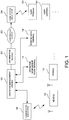
- FIG. 1 is a block diagram showing an overall configuration of a vehicle operation system that operates an automatic driving vehicle.
- a plurality of automatic driving vehicles (vehicles) 10 operate along a predetermined travel route.
- Each of the vehicles 10 is, for example, a passenger bus to be operated on a determined route, and makes rounds of certain areas while stopping at stopping places such as bus stops.
- An operation management center 12 includes a computer having a communicating function, and manages operation of the vehicles 10. That is, an operation plan of a plurality of vehicles 10 that includes putting into service (going into the determined route) and removing from service (going out from the determined route) of the vehicles 10 is prepared and stored.
- This operation plan includes an operation schedule indicating when and where the respective vehicles 10 travel (e.g., estimated (scheduled) time to arrive at a predetermined location). For example, the respective vehicles 10 will arrive at the predetermined location every 15 minutes if the vehicles travel at 20 km/h and distance between two vehicles 10 is 5 km.
- the operation management center 12 always grasps the location of each of the vehicles 10, and updates the operation schedule of each vehicle 10 to transmit the schedule to the corresponding vehicle 10 as needed.
- Each vehicle 10 controls travel (acceleration and deceleration) to arrive at the predetermined location at the estimated arrival time in accordance with the transmitted operation schedule.
- the operation schedule transmitted from the operation management center 12 to the vehicle 10 includes at least a command for travel speed, including the estimated arrival time for the vehicle 10 to arrive at the predetermined location.
- the operation management center 12 can automatically prepare a corresponding plan in case of emergency, such as failure of the vehicle 10.
- the operation management center 12 is connected to a plurality of communication base stations 14, and the plurality of communication base stations 14 are connected to the plurality of vehicles 10 via wireless communication. Therefore, the vehicle 10 can travel in accordance with the command from the operation management center 12 while exchanging information with the operation management center 12 through the communication.
- the operation management center 12 is connected to an operation management room terminal 16, and the operation management room terminal 16 accepts inputs of the necessary command or data in the operation management center 12, and provides a system operator with information by use of a display or the like.
- the operation management center 12 is connected to a parking area terminal 18.
- the parking area terminal 18 is provided in a parking area where the offline vehicle 10 that does not automatically travel is parked, and through the terminal, necessary information associated with the parking area is input and output.
- a charging facility is provided, and a battery to be mounted in the vehicle 10 can be charged if necessary.
- the operation management center 12 is connected to an information server 20.
- the information server 20 provides a user with operation information of the vehicle 10.
- the information server 20 is connected to a communication base station 24 via a communication network 22, and the communication base station 24 is connected to user terminals 26 via wireless communication.
- Each of the user terminals 26 may be a portable terminal such as a smartphone, and the user who gets in the vehicle 10 checks an operating situation of the vehicle 10. Note that a terminal is also provided at each stopping place, and information on the vehicle 10 that arrives at the stopping place next is displayed.
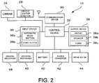
- FIG. 2 is a block diagram showing a configuration of the vehicle 10 that has an automatic mode to automatically drive in accordance with an instruction from the operation management center 12, and that automatically drives.
- a communication device 30 wirelessly communicates with the communication base station 14, to transmit and receive various types of information.
- the communication device 30 is connected to a control device 32, and the information to be transmitted and received in the communication device 30 is processed by the control device 32.
- the control device 32 controls overall operation, including the travel of the vehicle 10.
- the control device 32 is connected to a vehicle location detector 28, a camera 34, and an input device 36 that accepts input of data, and a vehicle location (present location) detected by the vehicle location detector 28, an image around the vehicle 10 that is captured in the camera 34, a travel command that is input from the input device 36 and the like are supplied to the control device 32.
- the vehicle location detector 28 includes a GPS device or the like and a gyroscope, and detects vehicle location information as needed, also by use of location information from beacons along the travel route, a transmitter of the stopping place or the like. The detected vehicle location, the captured peripheral image and others are appropriately supplied to the operation management center 12.
- the input device 36 includes an automatic mode button 36a for shifting to the automatic mode, a start button 36b to command start of the vehicle 10 at the stopping place or the like, and a mechanical manipulating part 36c to be manipulated by the operator. Furthermore, the control device 32 is connected to an output device 38 including a display 38a, a speaker 38b, and a horn 38c, from which necessary information is output.
- a battery 40, a power converter (for example, inverter) 42 and a drive motor 44 are mounted, and DC power from the battery 40 is converted to desired AC power by the power converter 42 and supplied to the drive motor 44. Consequently, the drive motor 44 is driven, and wheels are rotated by output of the motor, so that the vehicle 10 travels.
- a steering mechanism 46 controls steering of the vehicle 10.
- a braking mechanism 48 controls deceleration and stopping of the vehicle.
- the power converter 42, the steering mechanism 46 and the braking mechanism 48 are connected to the control device 32, and the control device 32 controls travel of the vehicle 10.
- the power converter 42 is controlled, to perform regenerative braking of the drive motor 44.
- the control device stores information on the travel route, and enables autonomous travel based on the vehicle location, camera information or the like.
- FIG. 3 is a diagram schematically showing an example of the travel route of the vehicle 10.
- a travel route 50 is a circuit route, and three vehicles 10 operate with almost equal distances in-between.
- Stopping places 52 are installed at appropriate intervals in accordance with uses of passengers.
- one of the stopping places 52 is a transfer stopping place to a separate bus stop or a train station, or another stopping place is close to certain passenger's home.
- one place (an entrance passage and an exit passage) of the travel route 50 is connected to a parking area 54, and the vehicle 10 is put into service from the parking area 54 to the travel route 50 or removed (bounced) from the travel route 50 to the parking area 54.
- FIG. 3 schematically shows the travel route 50, and an actual travel route 50 is not such a simple route, and includes, for example, an intersection or a turning point. Furthermore, turning (turnaround) travel at a predetermined turning point may be autonomously performed.
- a turning program that defines how to turn at the predetermined turning place is stored in the control device 32, and the turning travel is performed by executing the turning program.
- the operation of the plurality of vehicles 10 are basically managed by the operation management center 12. Consequently, for a vehicle 10 that is operable, vehicle information is stored together with an identification number of the vehicle in the operation management center 12. Furthermore, in the operation management center 12, the operation plan drafted using the operation management room terminal 16 or the like in advance is stored. That is, for example, putting a predetermined number of vehicles 10 into service on the travel route 50 one by one to start the operation is scheduled, and in a case where a vehicle 10 requires charging, removing the vehicle 10 from the service and putting a vehicle 10 on standby into the service is scheduled.
- the vehicles 10 are controlled to travel basically with equal distance apart. That is, each of the vehicles 10 provides the operation management center 12 with the information on the vehicle location as needed, and the operation management center 12 updates individual operation schedules so that the time difference between one vehicle to the next vehicle is always same at each stopping place, as needed, and transmits each of the schedules to each vehicle 10. Then, a vehicle speed (acceleration and deceleration) and the like of the vehicle 10 are controlled in accordance with the operation schedule sent from the operation management center 12. Furthermore, the number of the vehicles 10 to be operated is determined by the operation management center 12, and the vehicle 10 is automatically put in service or removed from the service in accordance with the instruction from the operation management center 12. Note that information on a battery residual capacity is also periodically supplied from the vehicle 10 to the operation management center 12, and a vehicle 10 having a battery residual capacity below a set value is automatically replaced with the charged vehicle 10.
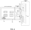
- FIG. 4 is a diagram showing a configuration example of a parking area.
- the parking area 54 includes an out of service zone A and an intermediate zone B. Note that the travel route 50 is in-service zone C.
- the out of service zone A is a space that accommodates the offline vehicle 10 out of service. Note that in the out of service zone A, the vehicle 10 can be charged, and the vehicle 10 is manually driven.
- the parking area terminal 18 provides the operation management center 12 with a number of vehicles 10 and a vehicle situation such as a charged situation in the out of service zone A, and the operation management center 12 grasps the number of the vehicles 10 to be put into service in the automatic driving, or the like.
- the intermediate zone B is located between the travel route 50 and the out of service zone A, and the vehicles 10 on standby for being put into service and the vehicles 10 for removal from service are arranged.
- This example indicates one vehicle 10 on standby for being put into service at a position that faces an into-service path toward the travel route 50, and one vehicle 10 on standby for removal from service at a position that faces an exit path from the travel route 50.
- the vehicle 10 of the out of service zone A is manually moved to a position on standby for being put into service, and enters to an in-service standby state.
- the vehicle 10 that leaves the travel route 50 is moved to a standby position in the intermediate zone B via an exit path, and stops at the standby position. Consequently, the automatic driving of the vehicle 10 ends, and the vehicle is then manually moved to the out of service zone A.
- the vehicle 10 that may be put into service first communicates with the operation management center 12. In a case where the vehicle 10 does not have any problems, the vehicle 10 is registered in an identification completed vehicle list in the operation management center 12. For example, for a vehicle 10 in the parking area 54, a mechanic or the like performs inspection and maintenance, and confirms whether the vehicle can shift to the automatic mode. Furthermore, for a vehicle that can be prepared for shifting to the automatic mode, it is displayed on the display 38a that the vehicle can shift to the automatic mode.
- the operation management center 12 transmits an into service instruction to the parking area terminal 18 at the time of putting a new vehicle into service. Note that in the parking area terminal 18, an in-service plan may be stored in advance, and putting vehicles into service may be confirmed from the parking area terminal to the operation management center 12.
- an operator manually moves a vehicle 10 that can be fielded, to the standby position, and displays to the effect that the vehicle can shift to the automatic mode.
- the operator depresses the automatic mode button 36a of the input device 36 to start in-service processing of the vehicle 10.
- FIG. 5 is a flowchart showing processing when putting the vehicle 10 into service.
- the vehicle 10 located at the in-service standby position determines whether the automatic mode button 36a is depressed (S11), and if YES in this determination, the vehicle transmits an automatic mode request and vehicle information to the operation management center 12 (S12).
- S11 the automatic mode button 36a
- S12 the vehicle transmits an automatic mode request and vehicle information to the operation management center 12
- an operator's task of depressing the automatic mode button 36a is required, and this is notified to the operation management center 12. Consequently, it is confirmed in the operation management center 12 that the operator recognizes the vehicle being put into service.
- voice input of "automatic driving start" or the like by the operator may be adopted.
- the automatic mode request is to transmit notification of completion of preparation for putting the vehicle 10 into service, and is automatically transmitted in response to the depressed automatic mode button 36a. Furthermore, the vehicle information is also transmitted to the operation management center 12 together with the automatic mode request.
- the vehicle information includes an identification number of the vehicle, information on specifications of the vehicle (a model code), and a state of the vehicle such as a battery residual capacity.
- the operation management center 12 confirms, based on the vehicle information, whether the vehicle 10 is a vehicle that matches an operation plan, that is, whether the vehicle 10 is an identified and listed vehicle that is instructed to be put into service, and if OK, the center transmits an automatic mode permission.
- the vehicle 10 enters a permission waiting state after the automatic mode request is transmitted, and determines whether the automatic mode permission can be received (S13). Then, in a case where the automatic mode permission from the operation management center 12 is received, the vehicle shifts to an automatic mode standby state (S14).
- the vehicle determines whether a travel start instruction from the operation management center 12 is received (S15).
- the operation management center 12 manages an operation of the plurality of vehicles 10, on the assumption that the vehicles arrives a stop place at a same interval. Therefore, the time of putting the new vehicle 10 into service also may fall in a predetermined range. For this purpose, the center transmits the travel start instruction at an appropriate time.
- the travel start instruction may include travel start time.
- notification of start of automatic travel is output from the speaker 38b, to inform the operator (S16). Furthermore, when informing, sounding of the horn 38c, flashing of a lamp, notification by voice or the like can be adopted, and voice output of "The automatic travel will start. Please push the start button.” or the like may be adopted. Note that, for example, in a case where abnormality occurs at this stage and the automatic travel is impossible, putting the vehicle 10 into service is discontinued and error processing is performed.
- the informing in the vehicle 10 is transmitted to the operation management center 12 together with a start instruction response indicating that travel start is possible (S17), and the vehicle enters a state of waiting for an operator's start manipulation while keeping the vehicle 10 in a stopped state.
- this start instruction response may be automatically transmitted, or transmitted in response to operator's confirmation input. That is, the operator performs a manipulation such as the confirmation input for the informing or the transmission to the operation management center 12, so that the operator can perform safety confirmation, and safety in subsequent starting can be ensured.
- the vehicle 10 travels as the automatic driving vehicle along the travel route 50 in the automatic mode.
- the start operation may be performed, for example, by depressing the start button 36b provided as one element of the input device 36 in the vehicle 10.
- S21 it is determined whether a predetermined time has elapsed (S21). That is, a time from when the vehicle 10 receives the travel start instruction is measured for determining whether the predetermined time has elapsed. If NO in this determination, the processing returns to S18. If YES in the determination of S21, the horn 38c is sounded (S22), and the stop holding state is then canceled (S23), and then the vehicle 10 starts (S24).
- the vehicle in the case where the travel start instruction is received from the operation management center 12 and operation start is informed, the vehicle is considered to be ready to start traveling. Consequently, in a case where there is no start manipulation by the operator within a predetermined time, the vehicle automatically starts, so that the in-service timing can be appropriately maintained. Furthermore, an occupants and people in the surrounding of the vehicle 10 can be informed of the start, for example, by sounding the horn 38c. Voice announcement of "the vehicle will start” may be output. Note that in a case where the travel start instruction is not received from the operation management center 12 and the operation start is not informed, starting without any start manipulation by the operator is prohibited.
- the operation management center 12 transmits the predetermined operation schedule of each vehicle 10 to control its traveling.
- the operation management center 12 always grasps the location of each vehicle 10 to update the operation schedule as needed, the operation schedule includes an instruction for acceleration and deceleration (the travel speed of the vehicle 10) so that each vehicle 10 basically arrives at each stopping place at same intervals.
- the operation management center 12 provides the vehicle 10 with information on a location of the other vehicle 10, so that an operator of the vehicle 10 can know the operating situation of the other vehicle and provide the user with the information.
- the operator of the vehicle 10 has to be an occupant who manipulates the vehicle 10, and the operator may be an occupant intended for vehicle manipulation, or a passenger who gets on the vehicle to reach a destination.
- the steering is autonomously controlled in the automatic mode.
- vehicle stop control When approaching the stopping place, vehicle stop control is entered at a predetermined location, to stop at the stopping place. After the stop, doors automatically open, and the occupants get on and off. When the vehicle definitely stops at all the stopping places, it is not necessary to take into consideration a stop request or the like from the occupant, but the vehicle may stop in response to the stop request.
- the vehicle After the vehicle stops, the vehicle releases the stop depending on operator's start manipulation, and enters start control to start. At this point, the vehicle 10 autonomously stops and starts at the stopping place. Afterward, the vehicle automatically travels in response to the instruction from the operation management center 12.
- FIG. 6 is a schematic view around the stopping place 52.
- a vehicle stop/pass determination point to determine whether the vehicle stops or passes at the stopping place 52 is set at a predetermined distance before the stopping place 52.
- a vehicle stop sequence start point to stop the vehicle at the stopping place 52 is set at a position that is closer to the stopping place 52 than this determination point is, and a start sequence end point to start from the stopping place 52 is set at a predetermined distance ahead of the stopping place 52.
- the stopping place 52 is a vehicle stop sequence end point and a start sequence start point. In this example, in a section between the vehicle stop sequence start point and the start sequence end point in the automatic mode, the instruction from the operation management center 12 is ignored, and the vehicle 10 autonomously travels.
- FIG. 7 is a flowchart of vehicle stop and start processing at the stopping place 52.
- the vehicle 10 reaches the vehicle stop/pass determination point (S41). Then, when reaching this determination point, the vehicle 10 requests the operation management center 12 for determination of vehicle stop/pass through communication, and acquires a determination result (S42). It is determined whether the determination result is vehicle stop or pass (S43), and in a case of vehicle pass, the processing for the vehicle stop at the stopping place is ended, and the vehicle 10 passes the stopping place 52.
Landscapes
- Engineering & Computer Science (AREA)
- Automation & Control Theory (AREA)
- Transportation (AREA)
- Mechanical Engineering (AREA)
- Human Computer Interaction (AREA)
- Physics & Mathematics (AREA)
- General Physics & Mathematics (AREA)
- Radar, Positioning & Navigation (AREA)
- Remote Sensing (AREA)
- Business, Economics & Management (AREA)
- Aviation & Aerospace Engineering (AREA)
- Primary Health Care (AREA)
- General Business, Economics & Management (AREA)
- Health & Medical Sciences (AREA)
- Economics (AREA)
- General Health & Medical Sciences (AREA)
- Human Resources & Organizations (AREA)
- Chemical & Material Sciences (AREA)
- Strategic Management (AREA)
- Marketing (AREA)
- Tourism & Hospitality (AREA)
- Combustion & Propulsion (AREA)
- Theoretical Computer Science (AREA)
- Traffic Control Systems (AREA)
- Management, Administration, Business Operations System, And Electronic Commerce (AREA)
- Electric Propulsion And Braking For Vehicles (AREA)
Abstract
Description
- The entire disclosure of Japanese Patent Application No.
2019-121405 filed on June 28, 2019 - The present disclosure relates to an automatic driving vehicle that automatically travels in accordance with an instruction from an operation management center, the operation management center, and a vehicle operation system.
- Heretofore, there have been various suggestions as to automatic driving of a vehicle. In
JP 2002-053044 A JP 2017-182137 A - In systems described in Patent Literatures 1 and 2, a center determines an operation schedule of an automatic driving vehicle, to control automatic driving of the vehicle. Here, in a case of operating a plurality of automatic driving vehicles, it becomes a problem as to how to put the automatic driving vehicle into service on a travel route. Particularly, in case of using an electrically-powered automatic driving vehicle, the automatic driving vehicle has to be periodically removed from service or put into service on the travel route for the purpose of charging a battery, and control in this case becomes a problem.
- According to the present disclosure, in an automatic driving vehicle having an automatic mode to automatically travel in accordance with an instruction from an operation management center, the automatic driving vehicle transmits an automatic mode request to the operation management center and enters a permission waiting state of being shiftable to the automatic mode by receiving a permission from the operation management center, and in a case where the automatic driving vehicle receives the permission from the operation management center in the permission waiting state, the automatic driving vehicle enters a start manipulation waiting state of waiting for a start manipulation by an operator, and in a case where there is the start manipulation by the operator in the start manipulation waiting state, travel in the automatic mode starts.
- In a state of being shiftable to the automatic mode before transmitting the automatic mode request, it may be displayed that the vehicle is shiftable to the automatic mode.
- In a case of starting from a state of being stopped at a stopping place in the automatic mode, the start may be enabled without receiving any permission from the operation management center.
- According to the present disclosure, in an operation management center that allows the automatic driving vehicle to automatically travel, the automatic mode request and vehicle information on the automatic driving vehicle are received from the automatic driving vehicle, it is determined based on the received vehicle information whether the automatic driving vehicle is a vehicle that matches an operation plan, and in a case of matching, the permission to shift to the automatic mode is transmitted.
- According to the present disclosure, in a vehicle operation system including an operation management center, and an automatic driving vehicle that automatically travels in accordance with an instruction from the operation management center, the automatic driving vehicle transmits, to the operation management center, an automatic mode request, and vehicle information on the automatic driving vehicle, and enters a permission waiting state of being shiftable to an automatic mode by receiving a permission from the operation management center, and the operation management center determines, based on the received vehicle information, whether the automatic driving vehicle is a vehicle that matches an operation plan, and transmits, to the automatic driving vehicle, the permission to shift to the automatic mode in a case of matching, and the automatic driving vehicle enters a start manipulation waiting state of waiting for a start manipulation by an operator upon receiving the permission from the operation management center in the permission waiting state, and starts travel in the automatic mode in a case where there is the start manipulation by the operator in the start manipulation waiting state.
- According to the present disclosure, automatic driving can appropriately start in accordance with an instruction from an operation management center to an automatic driving vehicle.
- An embodiment of the present disclosure will be described based on the following figures, wherein:
-
FIG. 1 is a block diagram showing an entire configuration of a vehicle operation system that operates an automatic driving vehicle; -
FIG. 2 is a block diagram showing a configuration of avehicle 10 that automatically drives; -
FIG. 3 is a diagram schematically showing an example of a travel route of thevehicle 10; -
FIG. 4 is a diagram showing a configuration example of a parking area; -
FIG. 5 is a flowchart showing processing when putting thevehicle 10 into service; -
FIG. 6 is a schematic view around a stoppingplace 52; and -
FIG. 7 is a flowchart of vehicle stop and start processing at the stoppingplace 52. - Hereinafter, an embodiment of the present disclosure will be described with reference to the drawings. Note that the present disclosure is not limited to the embodiment described herein.
-
FIG. 1 is a block diagram showing an overall configuration of a vehicle operation system that operates an automatic driving vehicle. In this system, a plurality of automatic driving vehicles (vehicles) 10 operate along a predetermined travel route. Each of thevehicles 10 is, for example, a passenger bus to be operated on a determined route, and makes rounds of certain areas while stopping at stopping places such as bus stops. - An
operation management center 12 includes a computer having a communicating function, and manages operation of thevehicles 10. That is, an operation plan of a plurality ofvehicles 10 that includes putting into service (going into the determined route) and removing from service (going out from the determined route) of thevehicles 10 is prepared and stored. This operation plan includes an operation schedule indicating when and where therespective vehicles 10 travel (e.g., estimated (scheduled) time to arrive at a predetermined location). For example, therespective vehicles 10 will arrive at the predetermined location every 15 minutes if the vehicles travel at 20 km/h and distance between twovehicles 10 is 5 km. Theoperation management center 12 always grasps the location of each of thevehicles 10, and updates the operation schedule of eachvehicle 10 to transmit the schedule to thecorresponding vehicle 10 as needed. Eachvehicle 10 controls travel (acceleration and deceleration) to arrive at the predetermined location at the estimated arrival time in accordance with the transmitted operation schedule. Thus, the operation schedule transmitted from theoperation management center 12 to thevehicle 10 includes at least a command for travel speed, including the estimated arrival time for thevehicle 10 to arrive at the predetermined location. Furthermore, theoperation management center 12 can automatically prepare a corresponding plan in case of emergency, such as failure of thevehicle 10. - The
operation management center 12 is connected to a plurality ofcommunication base stations 14, and the plurality ofcommunication base stations 14 are connected to the plurality ofvehicles 10 via wireless communication. Therefore, thevehicle 10 can travel in accordance with the command from theoperation management center 12 while exchanging information with theoperation management center 12 through the communication. - The
operation management center 12 is connected to an operationmanagement room terminal 16, and the operationmanagement room terminal 16 accepts inputs of the necessary command or data in theoperation management center 12, and provides a system operator with information by use of a display or the like. - The
operation management center 12 is connected to aparking area terminal 18. Theparking area terminal 18 is provided in a parking area where theoffline vehicle 10 that does not automatically travel is parked, and through the terminal, necessary information associated with the parking area is input and output. In the parking area, a charging facility is provided, and a battery to be mounted in thevehicle 10 can be charged if necessary. - The
operation management center 12 is connected to aninformation server 20. Theinformation server 20 provides a user with operation information of thevehicle 10. Theinformation server 20 is connected to acommunication base station 24 via acommunication network 22, and thecommunication base station 24 is connected touser terminals 26 via wireless communication. Each of theuser terminals 26 may be a portable terminal such as a smartphone, and the user who gets in thevehicle 10 checks an operating situation of thevehicle 10. Note that a terminal is also provided at each stopping place, and information on thevehicle 10 that arrives at the stopping place next is displayed. -
FIG. 2 is a block diagram showing a configuration of thevehicle 10 that has an automatic mode to automatically drive in accordance with an instruction from theoperation management center 12, and that automatically drives. Acommunication device 30 wirelessly communicates with thecommunication base station 14, to transmit and receive various types of information. Thecommunication device 30 is connected to acontrol device 32, and the information to be transmitted and received in thecommunication device 30 is processed by thecontrol device 32. Thecontrol device 32 controls overall operation, including the travel of thevehicle 10. - The
control device 32 is connected to avehicle location detector 28, acamera 34, and aninput device 36 that accepts input of data, and a vehicle location (present location) detected by thevehicle location detector 28, an image around thevehicle 10 that is captured in thecamera 34, a travel command that is input from theinput device 36 and the like are supplied to thecontrol device 32. Thevehicle location detector 28 includes a GPS device or the like and a gyroscope, and detects vehicle location information as needed, also by use of location information from beacons along the travel route, a transmitter of the stopping place or the like. The detected vehicle location, the captured peripheral image and others are appropriately supplied to theoperation management center 12. Theinput device 36 includes anautomatic mode button 36a for shifting to the automatic mode, astart button 36b to command start of thevehicle 10 at the stopping place or the like, and a mechanical manipulating part 36c to be manipulated by the operator. Furthermore, thecontrol device 32 is connected to anoutput device 38 including adisplay 38a, aspeaker 38b, and ahorn 38c, from which necessary information is output. - Furthermore, in the
vehicle 10, abattery 40, a power converter (for example, inverter) 42 and adrive motor 44 are mounted, and DC power from thebattery 40 is converted to desired AC power by thepower converter 42 and supplied to thedrive motor 44. Consequently, thedrive motor 44 is driven, and wheels are rotated by output of the motor, so that thevehicle 10 travels. Furthermore, asteering mechanism 46 controls steering of thevehicle 10. Additionally, abraking mechanism 48 controls deceleration and stopping of the vehicle. Thepower converter 42, thesteering mechanism 46 and thebraking mechanism 48 are connected to thecontrol device 32, and thecontrol device 32 controls travel of thevehicle 10. Note that thepower converter 42 is controlled, to perform regenerative braking of thedrive motor 44. Note that the control device stores information on the travel route, and enables autonomous travel based on the vehicle location, camera information or the like. -
FIG. 3 is a diagram schematically showing an example of the travel route of thevehicle 10. In this example, atravel route 50 is a circuit route, and threevehicles 10 operate with almost equal distances in-between. Stoppingplaces 52 are installed at appropriate intervals in accordance with uses of passengers. For example, one of the stoppingplaces 52 is a transfer stopping place to a separate bus stop or a train station, or another stopping place is close to certain passenger's home. Furthermore, one place (an entrance passage and an exit passage) of thetravel route 50 is connected to aparking area 54, and thevehicle 10 is put into service from theparking area 54 to thetravel route 50 or removed (bounced) from thetravel route 50 to theparking area 54. - Note that
FIG. 3 schematically shows thetravel route 50, and anactual travel route 50 is not such a simple route, and includes, for example, an intersection or a turning point. Furthermore, turning (turnaround) travel at a predetermined turning point may be autonomously performed. A turning program that defines how to turn at the predetermined turning place is stored in thecontrol device 32, and the turning travel is performed by executing the turning program. - The operation of the plurality of
vehicles 10 are basically managed by theoperation management center 12. Consequently, for avehicle 10 that is operable, vehicle information is stored together with an identification number of the vehicle in theoperation management center 12. Furthermore, in theoperation management center 12, the operation plan drafted using the operationmanagement room terminal 16 or the like in advance is stored. That is, for example, putting a predetermined number ofvehicles 10 into service on thetravel route 50 one by one to start the operation is scheduled, and in a case where avehicle 10 requires charging, removing thevehicle 10 from the service and putting avehicle 10 on standby into the service is scheduled. - Furthermore, in the operation, the
vehicles 10 are controlled to travel basically with equal distance apart. That is, each of thevehicles 10 provides theoperation management center 12 with the information on the vehicle location as needed, and theoperation management center 12 updates individual operation schedules so that the time difference between one vehicle to the next vehicle is always same at each stopping place, as needed, and transmits each of the schedules to eachvehicle 10. Then, a vehicle speed (acceleration and deceleration) and the like of thevehicle 10 are controlled in accordance with the operation schedule sent from theoperation management center 12. Furthermore, the number of thevehicles 10 to be operated is determined by theoperation management center 12, and thevehicle 10 is automatically put in service or removed from the service in accordance with the instruction from theoperation management center 12. Note that information on a battery residual capacity is also periodically supplied from thevehicle 10 to theoperation management center 12, and avehicle 10 having a battery residual capacity below a set value is automatically replaced with the chargedvehicle 10. -
FIG. 4 is a diagram showing a configuration example of a parking area. Theparking area 54 includes an out of service zone A and an intermediate zone B. Note that thetravel route 50 is in-service zone C. The out of service zone A is a space that accommodates theoffline vehicle 10 out of service. Note that in the out of service zone A, thevehicle 10 can be charged, and thevehicle 10 is manually driven. Theparking area terminal 18 provides theoperation management center 12 with a number ofvehicles 10 and a vehicle situation such as a charged situation in the out of service zone A, and theoperation management center 12 grasps the number of thevehicles 10 to be put into service in the automatic driving, or the like. - The intermediate zone B is located between the
travel route 50 and the out of service zone A, and thevehicles 10 on standby for being put into service and thevehicles 10 for removal from service are arranged. This example indicates onevehicle 10 on standby for being put into service at a position that faces an into-service path toward thetravel route 50, and onevehicle 10 on standby for removal from service at a position that faces an exit path from thetravel route 50. Thevehicle 10 of the out of service zone A is manually moved to a position on standby for being put into service, and enters to an in-service standby state. Furthermore, thevehicle 10 that leaves thetravel route 50 is moved to a standby position in the intermediate zone B via an exit path, and stops at the standby position. Consequently, the automatic driving of thevehicle 10 ends, and the vehicle is then manually moved to the out of service zone A. - The
vehicle 10 that may be put into service first communicates with theoperation management center 12. In a case where thevehicle 10 does not have any problems, thevehicle 10 is registered in an identification completed vehicle list in theoperation management center 12. For example, for avehicle 10 in theparking area 54, a mechanic or the like performs inspection and maintenance, and confirms whether the vehicle can shift to the automatic mode. Furthermore, for a vehicle that can be prepared for shifting to the automatic mode, it is displayed on thedisplay 38a that the vehicle can shift to the automatic mode. - The
operation management center 12 transmits an into service instruction to theparking area terminal 18 at the time of putting a new vehicle into service. Note that in theparking area terminal 18, an in-service plan may be stored in advance, and putting vehicles into service may be confirmed from the parking area terminal to theoperation management center 12. - In the
parking area 54, an operator manually moves avehicle 10 that can be fielded, to the standby position, and displays to the effect that the vehicle can shift to the automatic mode. For avehicle 10 that is stopped at the standby position (an in-service standby vehicle), the operator depresses theautomatic mode button 36a of theinput device 36 to start in-service processing of thevehicle 10. -
FIG. 5 is a flowchart showing processing when putting thevehicle 10 into service. Thevehicle 10 located at the in-service standby position determines whether theautomatic mode button 36a is depressed (S11), and if YES in this determination, the vehicle transmits an automatic mode request and vehicle information to the operation management center 12 (S12). Thus, when thevehicle 10 is put into service on thetravel route 50 as the automatic driving vehicle, an operator's task of depressing theautomatic mode button 36a is required, and this is notified to theoperation management center 12. Consequently, it is confirmed in theoperation management center 12 that the operator recognizes the vehicle being put into service. In place of the depression of theautomatic mode button 36a, for example, voice input of "automatic driving start" or the like by the operator may be adopted. Here, the automatic mode request is to transmit notification of completion of preparation for putting thevehicle 10 into service, and is automatically transmitted in response to the depressedautomatic mode button 36a. Furthermore, the vehicle information is also transmitted to theoperation management center 12 together with the automatic mode request. The vehicle information includes an identification number of the vehicle, information on specifications of the vehicle (a model code), and a state of the vehicle such as a battery residual capacity. - The
operation management center 12 confirms, based on the vehicle information, whether thevehicle 10 is a vehicle that matches an operation plan, that is, whether thevehicle 10 is an identified and listed vehicle that is instructed to be put into service, and if OK, the center transmits an automatic mode permission. - The
vehicle 10 enters a permission waiting state after the automatic mode request is transmitted, and determines whether the automatic mode permission can be received (S13). Then, in a case where the automatic mode permission from theoperation management center 12 is received, the vehicle shifts to an automatic mode standby state (S14). - When shifting to the automatic mode standby state, the vehicle determines whether a travel start instruction from the
operation management center 12 is received (S15). Theoperation management center 12 manages an operation of the plurality ofvehicles 10, on the assumption that the vehicles arrives a stop place at a same interval. Therefore, the time of putting thenew vehicle 10 into service also may fall in a predetermined range. For this purpose, the center transmits the travel start instruction at an appropriate time. The travel start instruction may include travel start time. - In a case where the travel start instruction is received in S15, notification of start of automatic travel is output from the
speaker 38b, to inform the operator (S16). Furthermore, when informing, sounding of thehorn 38c, flashing of a lamp, notification by voice or the like can be adopted, and voice output of "The automatic travel will start. Please push the start button." or the like may be adopted. Note that, for example, in a case where abnormality occurs at this stage and the automatic travel is impossible, putting thevehicle 10 into service is discontinued and error processing is performed. - In S16, the informing in the
vehicle 10 is transmitted to theoperation management center 12 together with a start instruction response indicating that travel start is possible (S17), and the vehicle enters a state of waiting for an operator's start manipulation while keeping thevehicle 10 in a stopped state. Here, this start instruction response may be automatically transmitted, or transmitted in response to operator's confirmation input. That is, the operator performs a manipulation such as the confirmation input for the informing or the transmission to theoperation management center 12, so that the operator can perform safety confirmation, and safety in subsequent starting can be ensured. - Next, it is determined whether there is the start manipulation by the operator in the state of waiting for the start manipulation (S18). Then, in a case where there is the start manipulation, a stop holding state is canceled (S19), and starting is performed (S20). Consequently, the
vehicle 10 travels as the automatic driving vehicle along thetravel route 50 in the automatic mode. Note that the start operation may be performed, for example, by depressing thestart button 36b provided as one element of theinput device 36 in thevehicle 10. - If NO in the determination of S18, it is determined whether a predetermined time has elapsed (S21). That is, a time from when the
vehicle 10 receives the travel start instruction is measured for determining whether the predetermined time has elapsed. If NO in this determination, the processing returns to S18. If YES in the determination of S21, thehorn 38c is sounded (S22), and the stop holding state is then canceled (S23), and then thevehicle 10 starts (S24). - Thus, in the case where the travel start instruction is received from the
operation management center 12 and operation start is informed, the vehicle is considered to be ready to start traveling. Consequently, in a case where there is no start manipulation by the operator within a predetermined time, the vehicle automatically starts, so that the in-service timing can be appropriately maintained. Furthermore, an occupants and people in the surrounding of thevehicle 10 can be informed of the start, for example, by sounding thehorn 38c. Voice announcement of "the vehicle will start" may be output. Note that in a case where the travel start instruction is not received from theoperation management center 12 and the operation start is not informed, starting without any start manipulation by the operator is prohibited. - Note that such processing during such putting into service cannot necessarily applied be only to putting vehicles into service from the parking area, but can also be applied when putting a
vehicle 10 that has the automatic mode canceled, for example, due to emergency stop, into service. - The
operation management center 12 transmits the predetermined operation schedule of eachvehicle 10 to control its traveling. Theoperation management center 12 always grasps the location of eachvehicle 10 to update the operation schedule as needed, the operation schedule includes an instruction for acceleration and deceleration (the travel speed of the vehicle 10) so that eachvehicle 10 basically arrives at each stopping place at same intervals. Note that theoperation management center 12 provides thevehicle 10 with information on a location of theother vehicle 10, so that an operator of thevehicle 10 can know the operating situation of the other vehicle and provide the user with the information. Here, the operator of thevehicle 10 has to be an occupant who manipulates thevehicle 10, and the operator may be an occupant intended for vehicle manipulation, or a passenger who gets on the vehicle to reach a destination. Note that in this example, the steering is autonomously controlled in the automatic mode. - When approaching the stopping place, vehicle stop control is entered at a predetermined location, to stop at the stopping place. After the stop, doors automatically open, and the occupants get on and off. When the vehicle definitely stops at all the stopping places, it is not necessary to take into consideration a stop request or the like from the occupant, but the vehicle may stop in response to the stop request.
- After the vehicle stops, the vehicle releases the stop depending on operator's start manipulation, and enters start control to start. At this point, the
vehicle 10 autonomously stops and starts at the stopping place. Afterward, the vehicle automatically travels in response to the instruction from theoperation management center 12. -
FIG. 6 is a schematic view around the stoppingplace 52. Thus, a vehicle stop/pass determination point to determine whether the vehicle stops or passes at the stoppingplace 52 is set at a predetermined distance before the stoppingplace 52. Then, a vehicle stop sequence start point to stop the vehicle at the stoppingplace 52 is set at a position that is closer to the stoppingplace 52 than this determination point is, and a start sequence end point to start from the stoppingplace 52 is set at a predetermined distance ahead of the stoppingplace 52. The stoppingplace 52 is a vehicle stop sequence end point and a start sequence start point. In this example, in a section between the vehicle stop sequence start point and the start sequence end point in the automatic mode, the instruction from theoperation management center 12 is ignored, and thevehicle 10 autonomously travels. -
FIG. 7 is a flowchart of vehicle stop and start processing at the stoppingplace 52. First, it is determined whether thevehicle 10 reaches the vehicle stop/pass determination point (S41). Then, when reaching this determination point, thevehicle 10 requests theoperation management center 12 for determination of vehicle stop/pass through communication, and acquires a determination result (S42). It is determined whether the determination result is vehicle stop or pass (S43), and in a case of vehicle pass, the processing for the vehicle stop at the stopping place is ended, and thevehicle 10 passes the stoppingplace 52. - In a case of vehicle stop in the determination of S43, it is determined whether the vehicle reaches the vehicle stop sequence start position at the predetermined distance before the stopping place 52 (S44). If YES in S44, the vehicle stop sequence is executed (S45). Consequently, the
vehicle 10 stops at the stopping place. Then, it is determined whether the vehicle stops (S46), and in case of the vehicle stop, it is determined whether there is the start operation (e.g., thestart button 36b is depressed) (S47). If YES in the determination of S47, the start sequence is executed (S48), for starting. Then, it is determined whether the vehicle reaches the start sequence end position (S49), and in a case where the end position is reached, the start sequence ends, and the stop and start control at the stoppingplace 52 ends.
Claims (5)
- An automatic driving vehicle (10) having an automatic mode to automatically travel in accordance with an instruction from an operation management center (12), whereinthe automatic driving vehicle (10) is configured to transmit an automatic mode request to the operation management center and to enter a permission waiting state of being shiftable to the automatic mode by receiving a permission from the operation management center,the automatic driving vehicle (10) being configured to, in a case where the permission from the operation management center is received in the permission waiting state, enter a start manipulation waiting state of waiting for a start manipulation of an operator, and to,in a case where there is the start manipulation of the operator in the start manipulation waiting state, start travel in the automatic mode.
- The automatic driving vehicle (10) according to claim 1, further configured to, in a state of being shiftable to the automatic mode before transmitting the automatic mode request, display that the vehicle is shiftable to the automatic mode.
- The automatic driving vehicle (10) according to claim 1 or 2, further configured to, in a case of starting from a state of being stopped at a stopping place in the automatic mode, enable the start without receiving any permission from the operation management center.
- An operation management center (12) configured to allow the automatic driving vehicle (10) according to claim 1 to automatically travel, wherein
the operation management center is configured to receive the automatic mode request and vehicle information on the automatic driving vehicle (10) from the automatic driving vehicle (10),
and to determine, based on the received vehicle information, whether the automatic driving vehicle (10) is a vehicle that matches an operation plan, and
and, in a case of matching, to transmit the permission to shift to the automatic mode. - A vehicle operation system including an operation management center, and an automatic driving vehicle (10) that is configured to automatically travel in accordance with an instruction from the operation management center (12), wherein
the automatic driving vehicle (10) is configured to transmit, to the operation management center (12), an automatic mode request, and vehicle information on the automatic driving vehicle (10), and to enter a permission waiting state of being shiftable to an automatic mode by receiving a permission from the operation management center (12), and
the operation management center (12) is configured to determine, based on the received vehicle information, whether the automatic driving vehicle (10) is a vehicle that matches an operation plan, and to transmit, to the automatic driving vehicle (10), the permission to shift to the automatic mode in a case of matching,
wherein the automatic driving vehicle is configured to enter a start manipulation waiting state of waiting for a start manipulation of an operator upon receiving the permission from the operation management center in the permission waiting state, and
to start travel in the automatic mode in a case where there is the start manipulation of the operator in the start manipulation waiting state.
Applications Claiming Priority (1)
| Application Number | Priority Date | Filing Date | Title |
|---|---|---|---|
| JP2019121405A JP7293914B2 (en) | 2019-06-28 | 2019-06-28 | Autonomous vehicle, operation control center and vehicle operation system |
Publications (1)
| Publication Number | Publication Date |
|---|---|
| EP3756979A1 true EP3756979A1 (en) | 2020-12-30 |
Family
ID=71409095
Family Applications (1)
| Application Number | Title | Priority Date | Filing Date |
|---|---|---|---|
| EP20181629.5A Pending EP3756979A1 (en) | 2019-06-28 | 2020-06-23 | Automatic driving vehicle, operation management center and vehicle operation system |
Country Status (4)
| Country | Link |
|---|---|
| US (1) | US20200409356A1 (en) |
| EP (1) | EP3756979A1 (en) |
| JP (2) | JP7293914B2 (en) |
| CN (2) | CN112141129B (en) |
Families Citing this family (1)
| Publication number | Priority date | Publication date | Assignee | Title |
|---|---|---|---|---|
| CN119744376A (en) * | 2022-07-22 | 2025-04-01 | 苏州宝时得电动工具有限公司 | Autonomous working device, autonomous working system and autonomous working control method |
Citations (5)
| Publication number | Priority date | Publication date | Assignee | Title |
|---|---|---|---|---|
| JP2002053044A (en) | 2000-08-09 | 2002-02-19 | Toyota Motor Corp | Operation control system, operation management device and automatic driving vehicle for automatic driving vehicle |
| DE102015002405A1 (en) * | 2015-02-24 | 2016-08-25 | Audi Ag | Method for traffic coordination of motor vehicles in a parking environment |
| JP2017182137A (en) | 2016-03-28 | 2017-10-05 | パナソニックIpマネジメント株式会社 | Control method for demand type operation management system and demand type operation management system |
| DE102016116858A1 (en) * | 2016-09-08 | 2018-03-08 | Knorr-Bremse Systeme für Nutzfahrzeuge GmbH | System and method for transferring a commercial vehicle |
| US20180261092A1 (en) * | 2017-03-13 | 2018-09-13 | Denso Ten Limited | In-vehicle device |
Family Cites Families (19)
| Publication number | Priority date | Publication date | Assignee | Title |
|---|---|---|---|---|
| JPH04143164A (en) * | 1990-10-05 | 1992-05-18 | Toshiba Corp | Automatic operation system |
| JP2005250952A (en) * | 2004-03-05 | 2005-09-15 | Toshiba Corp | Bus control device, bus operation management device and bus operation management system |
| CA2648972A1 (en) * | 2007-12-24 | 2009-06-24 | Yaron Mayer | System and method for improved electric cars and/or electric car batteries and/or improved infrastructures for recharging electric cars |
| JP6009367B2 (en) * | 2013-01-31 | 2016-10-19 | 北海道旅客鉄道株式会社 | Railroad crossing control system and railroad crossing control method for dual mode vehicle |
| JP6203571B2 (en) * | 2013-08-09 | 2017-09-27 | 日本信号株式会社 | Special automatic closure system |
| JP6426941B2 (en) * | 2014-08-20 | 2018-11-21 | 日立建機株式会社 | Control control device and driving simulation method of transport vehicle |
| US10664707B2 (en) * | 2014-10-06 | 2020-05-26 | Marc R. Hannah | Managed access system for traffic flow optimization |
| JP6375237B2 (en) * | 2015-01-28 | 2018-08-15 | 日立オートモティブシステムズ株式会社 | Automatic operation control device |
| KR101974768B1 (en) * | 2015-03-11 | 2019-05-02 | 가부시끼 가이샤 구보다 | A running control device for automatically running the working vehicle and the working vehicle |
| JP2016192079A (en) * | 2015-03-31 | 2016-11-10 | 株式会社デンソー | Automated vehicle control system |
| JP6451537B2 (en) * | 2015-07-21 | 2019-01-16 | 株式会社デンソー | Driving support control device |
| DE102015015833A1 (en) * | 2015-12-05 | 2017-06-08 | Man Truck & Bus Ag | Operating system for driving a vehicle, in particular a commercial vehicle |
| WO2017159801A1 (en) * | 2016-03-18 | 2017-09-21 | ヤンマー株式会社 | Autonomous traveling system |
| KR101736257B1 (en) * | 2017-02-10 | 2017-05-29 | 허윤성 | Method of managing driving in commuter bus |
| JP6925133B2 (en) * | 2017-02-13 | 2021-08-25 | 株式会社クボタ | Satellite radio sensitivity distribution management system for work platforms |
| JP2018170991A (en) * | 2017-03-31 | 2018-11-08 | ヤンマー株式会社 | Autonomous traveling system for agricultural vehicles |
| JP6573945B2 (en) * | 2017-10-12 | 2019-09-11 | みこらった株式会社 | Self-driving car |
| KR20190064302A (en) * | 2017-11-30 | 2019-06-10 | 현대자동차주식회사 | Method and apparatus for controlling driving mode of autonomous driving vehicle |
| CN109725638A (en) * | 2018-12-12 | 2019-05-07 | 北京百度网讯科技有限公司 | Function for Automatic Pilot authorization method, device, system and storage medium |
-
2019
- 2019-06-28 JP JP2019121405A patent/JP7293914B2/en active Active
-
2020
- 2020-06-23 CN CN202010580559.1A patent/CN112141129B/en active Active
- 2020-06-23 CN CN202311340760.2A patent/CN117400965A/en active Pending
- 2020-06-23 EP EP20181629.5A patent/EP3756979A1/en active Pending
- 2020-06-26 US US16/912,971 patent/US20200409356A1/en not_active Abandoned
-
2023
- 2023-06-08 JP JP2023094741A patent/JP7468755B2/en active Active
Patent Citations (5)
| Publication number | Priority date | Publication date | Assignee | Title |
|---|---|---|---|---|
| JP2002053044A (en) | 2000-08-09 | 2002-02-19 | Toyota Motor Corp | Operation control system, operation management device and automatic driving vehicle for automatic driving vehicle |
| DE102015002405A1 (en) * | 2015-02-24 | 2016-08-25 | Audi Ag | Method for traffic coordination of motor vehicles in a parking environment |
| JP2017182137A (en) | 2016-03-28 | 2017-10-05 | パナソニックIpマネジメント株式会社 | Control method for demand type operation management system and demand type operation management system |
| DE102016116858A1 (en) * | 2016-09-08 | 2018-03-08 | Knorr-Bremse Systeme für Nutzfahrzeuge GmbH | System and method for transferring a commercial vehicle |
| US20180261092A1 (en) * | 2017-03-13 | 2018-09-13 | Denso Ten Limited | In-vehicle device |
Also Published As
| Publication number | Publication date |
|---|---|
| CN117400965A (en) | 2024-01-16 |
| JP2021009431A (en) | 2021-01-28 |
| CN112141129B (en) | 2023-09-22 |
| JP7468755B2 (en) | 2024-04-16 |
| US20200409356A1 (en) | 2020-12-31 |
| CN112141129A (en) | 2020-12-29 |
| JP2023105212A (en) | 2023-07-28 |
| JP7293914B2 (en) | 2023-06-20 |
Similar Documents
| Publication | Publication Date | Title |
|---|---|---|
| EP3761139B1 (en) | Automatic driving vehicle | |
| US10062289B2 (en) | Device and method for assisting a driver in driving his vehicle into and out of a parking space in a parking facility | |
| JP7591104B2 (en) | Method and apparatus for providing a driver interface - Patents.com | |
| JP6441143B2 (en) | Electric bus and charging system | |
| US11661081B2 (en) | Control device for automated driving vehicle | |
| JP2003276606A (en) | System and method for controlling train | |
| JP7468755B2 (en) | Autonomous bus, operation control center and operation control system | |
| WO2020116572A1 (en) | Operation management system for electric vehicle | |
| JP4807308B2 (en) | Traffic system, vehicle and traffic signal controller | |
| JP3432714B2 (en) | Train operation management device | |
| US20200406933A1 (en) | Automatic driving vehicle and operation management system | |
| KR101089819B1 (en) | System for warning information of train driver to use wireless communication data | |
| KR101943017B1 (en) | Management system for car which unification of accident management and allocation management | |
| KR102447344B1 (en) | Demand forecasting dynamic public transportation system and public transportation operation method based on self-driving vehicles | |
| KR101760681B1 (en) | Method of bus assignment in diagnosing trouble of bus | |
| KR101551274B1 (en) | Method of bus assignment in diagnosing trouble of bus | |
| JP2002279579A (en) | Vehicle running control method and system | |
| JP2020015340A (en) | Vehicle control system and vehicle control device | |
| KR20240007857A (en) | Method and apparatus of providing interface for vehicle operation | |
| KR20220075938A (en) | control mothod for unmanned bus | |
| JPH11240451A (en) | Train crew supporting unit | |
| JPH0399974A (en) | Train passenger information guiding system |
Legal Events
| Date | Code | Title | Description |
|---|---|---|---|
| PUAI | Public reference made under article 153(3) epc to a published international application that has entered the european phase |
Free format text: ORIGINAL CODE: 0009012 |
|
| STAA | Information on the status of an ep patent application or granted ep patent |
Free format text: STATUS: REQUEST FOR EXAMINATION WAS MADE |
|
| 17P | Request for examination filed |
Effective date: 20200623 |
|
| AK | Designated contracting states |
Kind code of ref document: A1 Designated state(s): AL AT BE BG CH CY CZ DE DK EE ES FI FR GB GR HR HU IE IS IT LI LT LU LV MC MK MT NL NO PL PT RO RS SE SI SK SM TR |
|
| AX | Request for extension of the european patent |
Extension state: BA ME |
|
| STAA | Information on the status of an ep patent application or granted ep patent |
Free format text: STATUS: EXAMINATION IS IN PROGRESS |
|
| 17Q | First examination report despatched |
Effective date: 20230109 |
|
| GRAP | Despatch of communication of intention to grant a patent |
Free format text: ORIGINAL CODE: EPIDOSNIGR1 |
|
| STAA | Information on the status of an ep patent application or granted ep patent |
Free format text: STATUS: GRANT OF PATENT IS INTENDED |
|
| RIC1 | Information provided on ipc code assigned before grant |
Ipc: B62D 15/02 20060101AFI20260204BHEP Ipc: B60W 60/00 20200101ALI20260204BHEP Ipc: B60W 30/06 20060101ALI20260204BHEP Ipc: B60W 50/08 20200101ALI20260204BHEP Ipc: G08G 1/127 20060101ALI20260204BHEP |
|
| INTG | Intention to grant announced |
Effective date: 20260220 |