EP3756972A1 - Vorläuferfahrzeug und verfahren zur fernsteuerung von zügen - Google Patents
Vorläuferfahrzeug und verfahren zur fernsteuerung von zügen Download PDFInfo
- Publication number
- EP3756972A1 EP3756972A1 EP20182081.8A EP20182081A EP3756972A1 EP 3756972 A1 EP3756972 A1 EP 3756972A1 EP 20182081 A EP20182081 A EP 20182081A EP 3756972 A1 EP3756972 A1 EP 3756972A1
- Authority
- EP
- European Patent Office
- Prior art keywords
- train
- trolley
- rail
- sensor
- rail trolley
- Prior art date
- Legal status (The legal status is an assumption and is not a legal conclusion. Google has not performed a legal analysis and makes no representation as to the accuracy of the status listed.)
- Pending
Links
Images


Classifications
-
- B—PERFORMING OPERATIONS; TRANSPORTING
- B61—RAILWAYS
- B61L—GUIDING RAILWAY TRAFFIC; ENSURING THE SAFETY OF RAILWAY TRAFFIC
- B61L23/00—Control, warning or like safety means along the route or between vehicles or trains
-
- B—PERFORMING OPERATIONS; TRANSPORTING
- B61—RAILWAYS
- B61L—GUIDING RAILWAY TRAFFIC; ENSURING THE SAFETY OF RAILWAY TRAFFIC
- B61L23/00—Control, warning or like safety means along the route or between vehicles or trains
- B61L23/04—Control, warning or like safety means along the route or between vehicles or trains for monitoring the mechanical state of the route
- B61L23/041—Obstacle detection
Definitions
- the present invention generally refers to systems for driving trains on a railway network.
- the present invention relates to a railway trolley and a method for the remote guidance of trains along a predefined route on a railway network.
- ICT Information and Communication
- driverless trains have been used for several years.
- a main aim of the present invention is to provide a solution offering substantial improvements over the known state of the art, in particular having minimal impact on train control systems to be guided autonomously and allowing, at the same time, to meet the highest possible safety standards.
- an object of the present invention is to provide a solution which can be used easily, with new trains and also with trains already in service.
- Another object of the present invention is to provide a solution for putting into service guided trains in an autonomous manner, highly reliable, relatively easy to produce and at competitive costs.
- suitable or “arranged” or “configured” is used herein to refer to any component as a whole, or any part of a component, or a combination of components, it is to be understood that it means and includes either the structure and / or the configuration and / or the shape and / or the positioning of the component or of the part that this term designates, including for electronic means, electronic circuits as well as software codes and / or algorithms or complete programs stored or running.
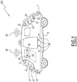
- the figure 1 schematically illustrates an example of a railway trolley according to the present invention, designated by the reference number 100.
- the rail trolley 100 is designed to guide trains 150 having one or more freight cars or passenger cars, on a rail network 200.
- train 150 is a freight train having one locomotive 151 and four cars 152.
- the train 150 to be guided by the rail trolley 100 can be of any type, for example a passenger train, and can include any number of wagons or cars; it can even consist of a single railcar.
- control-command device 30 is configured to emit, on the basis of at least one signal received from one or more first sensor (s) 10, control signals capable of remote control. walking the train 150 identified by the identification device 1, along the predefined route.
- the rail trolley 100 also comprises one or more second (s) sensor (s) 20 for monitoring, during travel, an area located behind (B) the rail trolley 100 with respect to the direction of travel.
- the control device 30 is operatively connected to the second sensor (s) 20 and is configured to send the control signals capable of remotely controlling the running of the train 150 identified by the identification device 1, along the predefined route, further on the basis of at least one signal received from one or more second sensor (s) 20.
- At least one communication device 40 is provided on board the rail trolley 100, which communication device 40 is operatively connected to the I&C device 30 and is configured to wirelessly send the control signals. command sent to the control system 153 of the train 150 guided along the predefined route, via a mobile communication network 202.
- the communication between the trolley 100 and the control system on board a train 150 is carried out in unicast manner, that is to say by point to point, and provided by the network 202.
- the identification device 1 can consist of any system capable of detecting an element representative of a train and of sending it to the control-command device 30 to be analyzed and to make it possible to verify whether the detected train is indeed the one to be detected. guide.
- the identification device 1 may include a video camera capable of capturing an image of the train 150, a reader for bar codes attached to the train or a radio transceiver associated with radio tags (RFID) placed. on train 150.
- RFID radio tags
- control-command device 30 validates the train 150 to be guided along the predefined route on the rail network 200, for example by combining the element representative of a train received by the identification device 1 , with mission profiles prerecorded in a memory specific to the control system.
- the control device 30 used in the rail trolley 100 comprises a processor-based system, of a commercially available type, suitably provided with electronic circuits and programmed with software code to perform the control-command functionalities of the associated train. 150, these functionalities being designed for the rail trolley 100 according to the present invention.
- control device 30 is configured to hold the train 150 at a dynamically adjustable distance (D) while running.
- control device 30 is configured to dynamically adjust the distance (D) between the trolley 100 and the guided train 150, as a function of one or more parameter (s) relating to at least one of the trains to be guided to the predefined route, and / or rail trolley 100 itself.
- control device 30 is configured to dynamically adjust the distance (D) by considering the actual speed, the weight, the braking capacity of the trolley 100, the worst possible slope profile between the trolley 100 and the train associated 150, the characteristics of the track of the railway network which will be traversed, for example the slope, as well as the presence and the characteristics of the curves.
- the first sensor (s) 10 used on board the rail trolley 100 include (s) at least one infrared sensor 11.
- the first sensors 10 comprise a plurality of different sensors and, in particular, in addition to the infrared sensor 11, at least one additional sensor selected from the group including a sonar, a radar and a lidar.
- the first sensors include an infrared sensor 11, a sonar 12, a radar 13 and a lidar 14.
- the second sensor (s) 20 used on board the rail trolley 100 also include at least one infrared sensor 21.
- the second sensors 20 comprise a plurality of different sensors and, in particular, in addition to the infrared sensor 21, at least one additional sensor selected from the group including a sonar, a radar and a lidar.
- the second sensors 20 comprise an infrared sensor 21, a sonar 22, a radar 23 and a lidar 24.
- the set of first (s) and / or second (s) sensors installed on board the trolley 100, in combination with software stored in the control-command device 30, constitutes a system for detecting and recognizing the environment and, in particular of the front zone (A) and of the rear zone (B) of the trolley 100, around and along the rails, based on multi-physical detection, that is to say based on several phenomena physical.
- This multi-physical detection uses the signals from the diversified sensors which are sent to the control-command device 30 which processes them in real time for the detection of obstacles or of any dangerous situation for the safety of the guided train 150.
- the command and control device 30 considers the extended visible infrared channel as a priority and supplemented by radar vision and detection by sonar and / or lidar for the respective detection at long and short distance.
- the combination of channels is carried out to build, for example, a global obstacle detection based on the merger and the vote according to a formula defined by the designer.
- the rail trolley 100 comprises an autonomous power unit 5 for powering the trolley 100 autonomously while walking along said predefined route.
- this autonomous power supply unit 5 comprises one or more rechargeable batteries.
- the batteries can be charged when the trolley 100 is parked in a charging station or during the service journey by transmitting energy from the guided train 150 to the trolley 100, for example with wireless remote charging systems.
- the trolley is advantageously equipped on each of its ends with a secure connection device to a recharging socket located on dedicated fixed power supply terminals themselves judiciously located on the rail network.
- the power supply terminals are communicating in order to establish, under safety conditions, the connection of the trolley to the terminal socket.
- the bollard has an absorption capacity to cushion any excessively rapid contact of the trolley.
- the process of recharging the trolley on the motor power supply terminals is completely autonomous.
- the trolley assesses whether its level of autonomy is sufficient to carry out its next mission. If this is not the case, the trolley proceeds freely, that is to say without driving any train, in a service maneuver having as its object the recharging of motricity energy.
- the choice of the charging station is made by the trolley itself based on criteria of proximity and operational status of the stations in the vicinity of the trolley. As the stations are connected objects, their availability is checked remotely before initiating the charging service maneuver.
- the rail trolley 100 comprises a first manual driving system 45, that is to say with a driver who guides the trolley 100, and a second autonomous driving system 50, c ' that is, driverless.
- the second autonomous driving system 50 can be controlled remotely, for example by an operator located in a control room of the network 200.
- the manual driving system 45 and that of autonomous driving are operatively connected to said command and control device 30, so that said second autonomous driving system 50 is inhibited at least until the train 150 at guide along said predefined route is uniquely identified.
- a method 300 for driving trains 150 having one or more wagons 152 on a railway network 200 according to the present invention will be described below with reference to figure 3 .
- said step 305 or the trolley 100 is univocally associated with the train 150 to be guided, is carried out under the direct control of an operator who for example uses the manual driving system 45 and drives the trolley 100 at most. possible close to train 150 so that there are no ambiguities about which train to take charge of.
- said step 310 of remotely guiding the associated train 150 with the trolley 100 comprises dynamically adjusting the distance (D) between the rail trolley 100 supplied and the guided train 150 as a function of one or more parameters (s) relating to at least one of said guided train 150, and / or to a predefined route, and / or to the rail trolley 100 provided.
- the trolley and in particular the command and control device 30 is configured so that the maximum distance between the trolley and the train controlled by the trolley is less than a maximum threshold.
- the train control system 153 150 is suitable for determining the position of the train and for defining, advantageously by interacting with the signaling infrastructure at the edge of the track, a safety envelope around the train, said envelope including at least the train, the trolley and the distance between the train and the associated trolley.
- the signaling infrastructure comprises several zone controllers, or ZC, for “Zone Controller” in English.
- the rail network is subdivided into a plurality of zones, a ZC is associated with each of these zones.
- a ZC is notably in charge, on the one hand, of monitoring the presence of trains in the associated zone and, on the other hand, of providing movement authorizations to trains, which are likely to guarantee their movement safety, c 'that is to say for example not to provide a train with an authorization movement that would lead him to go beyond the train in front of him.
- Each zone is subdivided into a plurality of townships.
- the ZC places the “occupied” value in a first state, the blocks having an intersection with the security envelope.
- the first state of the blocks in which no train is found at the current time that is to say of the blocks which do not have an intersection with a safety envelope, takes the value "free".
- occupancy information for each block of a zone is determined by the ZC and movement authorizations can be issued to the train while ensuring the safe movement of trains.
- the train 150 control system 153 is thus able to extend the safety envelope at least to the trolley.
- the trolley is coupled / connected to the train with which it is associated via a magnetic coupling system.
- the train and the trolley are therefore coupled to each other and represent a single vehicle for the signaling infrastructure.
- the autonomous and remote guidance is performed outside the control-command system installed on board the train 150, which limits intrusion into the architecture of the trains to be guided, which must simply provide a capacity of remote control.
- the rail trolley 100 and the method 300 according to the present invention can achieve very high level performance and can be reused from one train to another since each trolley 100 can be used for an entire fleet of trains. , simply by means of adequate computer programming of its own software with a huge advantage on management costs.
- the method 300 and the rail trolley 100 are subject to modifications and variations.
- communication with the various trains at guide can be carried out with any secure communications system, for example encrypted
- the data integrity check can be carried out by conventional redundancy techniques and according to any applicable protocol.
Landscapes
- Engineering & Computer Science (AREA)
- Mechanical Engineering (AREA)
- Train Traffic Observation, Control, And Security (AREA)
- Electric Propulsion And Braking For Vehicles (AREA)
Applications Claiming Priority (1)
| Application Number | Priority Date | Filing Date | Title |
|---|---|---|---|
| FR1906775A FR3097516B1 (fr) | 2019-06-24 | 2019-06-24 | Trolley ferroviaire et procede pour le guidage a distance de trains |
Publications (1)
| Publication Number | Publication Date |
|---|---|
| EP3756972A1 true EP3756972A1 (de) | 2020-12-30 |
Family
ID=68581898
Family Applications (1)
| Application Number | Title | Priority Date | Filing Date |
|---|---|---|---|
| EP20182081.8A Pending EP3756972A1 (de) | 2019-06-24 | 2020-06-24 | Vorläuferfahrzeug und verfahren zur fernsteuerung von zügen |
Country Status (2)
| Country | Link |
|---|---|
| EP (1) | EP3756972A1 (de) |
| FR (1) | FR3097516B1 (de) |
Cited By (1)
| Publication number | Priority date | Publication date | Assignee | Title |
|---|---|---|---|---|
| WO2022232433A1 (en) * | 2021-04-28 | 2022-11-03 | Parallel Systems, Inc. | System and/or method for platooning |
Citations (4)
| Publication number | Priority date | Publication date | Assignee | Title |
|---|---|---|---|---|
| EP0117763A2 (de) * | 1983-03-01 | 1984-09-05 | Tai-Her Yang | Zug mit Vorläufer |
| US5786750A (en) * | 1996-05-10 | 1998-07-28 | The United States Of America As Represented By The Secretary Of The Navy | Pilot vehicle which is useful for monitoring hazardous conditions on railroad tracks |
| WO2008017821A2 (en) * | 2006-08-07 | 2008-02-14 | Powell, Stephen, David | Mobile threat detection |
| WO2020030510A1 (en) * | 2018-08-07 | 2020-02-13 | Bombardier Transportation Gmbh | Railway drone vehicle and railway vehicle system |
-
2019
- 2019-06-24 FR FR1906775A patent/FR3097516B1/fr active Active
-
2020
- 2020-06-24 EP EP20182081.8A patent/EP3756972A1/de active Pending
Patent Citations (4)
| Publication number | Priority date | Publication date | Assignee | Title |
|---|---|---|---|---|
| EP0117763A2 (de) * | 1983-03-01 | 1984-09-05 | Tai-Her Yang | Zug mit Vorläufer |
| US5786750A (en) * | 1996-05-10 | 1998-07-28 | The United States Of America As Represented By The Secretary Of The Navy | Pilot vehicle which is useful for monitoring hazardous conditions on railroad tracks |
| WO2008017821A2 (en) * | 2006-08-07 | 2008-02-14 | Powell, Stephen, David | Mobile threat detection |
| WO2020030510A1 (en) * | 2018-08-07 | 2020-02-13 | Bombardier Transportation Gmbh | Railway drone vehicle and railway vehicle system |
Cited By (6)
| Publication number | Priority date | Publication date | Assignee | Title |
|---|---|---|---|---|
| WO2022232433A1 (en) * | 2021-04-28 | 2022-11-03 | Parallel Systems, Inc. | System and/or method for platooning |
| US11548542B2 (en) | 2021-04-28 | 2023-01-10 | Parallel Systems, Inc. | System and/or method for platooning |
| US11708102B2 (en) | 2021-04-28 | 2023-07-25 | Parallel Systems, Inc. | System and/or method for platooning |
| US11926355B2 (en) | 2021-04-28 | 2024-03-12 | Parallel Systems, Inc. | System and/or method for platooning |
| US12091070B2 (en) | 2021-04-28 | 2024-09-17 | Parallel Systems, Inc. | System and/or method for platooning |
| US12258056B2 (en) | 2021-04-28 | 2025-03-25 | Parallel Systems, Inc. | System and/or method for platooning |
Also Published As
| Publication number | Publication date |
|---|---|
| FR3097516A1 (fr) | 2020-12-25 |
| FR3097516B1 (fr) | 2023-01-06 |
Similar Documents
| Publication | Publication Date | Title |
|---|---|---|
| US11062414B1 (en) | System and method for autonomous vehicle ride sharing using facial recognition | |
| US12050460B1 (en) | Autonomous vehicle remote disablement | |
| US10688991B2 (en) | Systems and methods for unprotected maneuver mitigation in autonomous vehicles | |
| US20220083060A1 (en) | Autonomous driving vehicle | |
| EP3395642B1 (de) | Verbessertes system zur automatischen kontrolle von zügen, und entsprechendes verfahren | |
| US20210200207A1 (en) | Autonomous vehicle sensor security system | |
| EP3408721B1 (de) | Automatisches transportsystem | |
| EP2310924B1 (de) | Automatisiertes kollektives transportsystem | |
| US20170300053A1 (en) | Self-driving vehicle systems and methods | |
| US11024162B2 (en) | Traffic management system | |
| US10487564B2 (en) | Door actuator adjustment for autonomous vehicles | |
| US12055936B2 (en) | Autonomous rideshare rebalancing | |
| US20180224860A1 (en) | Autonomous vehicle movement around stationary vehicles | |
| US20220050475A1 (en) | Autonomous vehicle signaling system | |
| FR2974936A1 (fr) | Systeme de guidage automatique de vehicule electrique dans un espace dedie au stationnement, vehicule et procede associes | |
| EP3756972A1 (de) | Vorläuferfahrzeug und verfahren zur fernsteuerung von zügen | |
| US20230234561A1 (en) | Method and apparatus for providing route guidance | |
| US12367492B2 (en) | Proximity-based token issuance system | |
| CA2962887A1 (fr) | Procede de gestion de circulation d'un vehicule ferroviaire avec protection anticollision laterale | |
| CN114435352A (zh) | 用于野生动物园放养区的无人游览车的自动驾驶系统 | |
| JP7807535B2 (ja) | デュアルモードの自動式公共/個人輸送システム | |
| EP4453512A1 (de) | Verfahren zur modellierung einer taktischen umgebung eines kraftfahrzeugs |
Legal Events
| Date | Code | Title | Description |
|---|---|---|---|
| PUAI | Public reference made under article 153(3) epc to a published international application that has entered the european phase |
Free format text: ORIGINAL CODE: 0009012 |
|
| STAA | Information on the status of an ep patent application or granted ep patent |
Free format text: STATUS: THE APPLICATION HAS BEEN PUBLISHED |
|
| AK | Designated contracting states |
Kind code of ref document: A1 Designated state(s): AL AT BE BG CH CY CZ DE DK EE ES FI FR GB GR HR HU IE IS IT LI LT LU LV MC MK MT NL NO PL PT RO RS SE SI SK SM TR |
|
| AX | Request for extension of the european patent |
Extension state: BA ME |
|
| STAA | Information on the status of an ep patent application or granted ep patent |
Free format text: STATUS: REQUEST FOR EXAMINATION WAS MADE |
|
| 17P | Request for examination filed |
Effective date: 20210127 |
|
| RBV | Designated contracting states (corrected) |
Designated state(s): AL AT BE BG CH CY CZ DE DK EE ES FI FR GB GR HR HU IE IS IT LI LT LU LV MC MK MT NL NO PL PT RO RS SE SI SK SM TR |
|
| STAA | Information on the status of an ep patent application or granted ep patent |
Free format text: STATUS: EXAMINATION IS IN PROGRESS |
|
| 17Q | First examination report despatched |
Effective date: 20230406 |
|
| P01 | Opt-out of the competence of the unified patent court (upc) registered |
Effective date: 20230823 |
|
| RAP1 | Party data changed (applicant data changed or rights of an application transferred) |
Owner name: ALSTOM HOLDINGS |
|
| GRAP | Despatch of communication of intention to grant a patent |
Free format text: ORIGINAL CODE: EPIDOSNIGR1 |
|
| STAA | Information on the status of an ep patent application or granted ep patent |
Free format text: STATUS: GRANT OF PATENT IS INTENDED |
|
| INTG | Intention to grant announced |
Effective date: 20251212 |
|
| GRAS | Grant fee paid |
Free format text: ORIGINAL CODE: EPIDOSNIGR3 |
|
| GRAA | (expected) grant |
Free format text: ORIGINAL CODE: 0009210 |
|
| STAA | Information on the status of an ep patent application or granted ep patent |
Free format text: STATUS: THE PATENT HAS BEEN GRANTED |