EP3756938A1 - Système de thermorégulation - Google Patents
Système de thermorégulation Download PDFInfo
- Publication number
- EP3756938A1 EP3756938A1 EP19216193.3A EP19216193A EP3756938A1 EP 3756938 A1 EP3756938 A1 EP 3756938A1 EP 19216193 A EP19216193 A EP 19216193A EP 3756938 A1 EP3756938 A1 EP 3756938A1
- Authority
- EP
- European Patent Office
- Prior art keywords
- temperature control
- battery
- battery packs
- individual
- control system
- Prior art date
- Legal status (The legal status is an assumption and is not a legal conclusion. Google has not performed a legal analysis and makes no representation as to the accuracy of the status listed.)
- Pending
Links
- 238000005496 tempering Methods 0.000 title description 4
- 238000001816 cooling Methods 0.000 claims description 58
- 238000010438 heat treatment Methods 0.000 claims description 58
- 238000002156 mixing Methods 0.000 claims description 22
- 230000033228 biological regulation Effects 0.000 claims description 6
- 238000004891 communication Methods 0.000 claims description 2
- 239000000203 mixture Substances 0.000 claims description 2
- 210000004027 cell Anatomy 0.000 description 17
- 238000009434 installation Methods 0.000 description 4
- 238000002485 combustion reaction Methods 0.000 description 3
- 238000011161 development Methods 0.000 description 3
- 230000018109 developmental process Effects 0.000 description 3
- 230000001105 regulatory effect Effects 0.000 description 3
- 239000000446 fuel Substances 0.000 description 2
- 239000007789 gas Substances 0.000 description 2
- 230000005855 radiation Effects 0.000 description 2
- 239000002918 waste heat Substances 0.000 description 2
- HBBGRARXTFLTSG-UHFFFAOYSA-N Lithium ion Chemical compound [Li+] HBBGRARXTFLTSG-UHFFFAOYSA-N 0.000 description 1
- 238000010276 construction Methods 0.000 description 1
- 230000001276 controlling effect Effects 0.000 description 1
- 230000008878 coupling Effects 0.000 description 1
- 238000010168 coupling process Methods 0.000 description 1
- 238000005859 coupling reaction Methods 0.000 description 1
- 230000007423 decrease Effects 0.000 description 1
- 230000001419 dependent effect Effects 0.000 description 1
- 238000013461 design Methods 0.000 description 1
- 238000007599 discharging Methods 0.000 description 1
- 230000007613 environmental effect Effects 0.000 description 1
- 238000000265 homogenisation Methods 0.000 description 1
- 229910001416 lithium ion Inorganic materials 0.000 description 1
- 238000000034 method Methods 0.000 description 1
- 210000000352 storage cell Anatomy 0.000 description 1
- 238000012546 transfer Methods 0.000 description 1
- XLYOFNOQVPJJNP-UHFFFAOYSA-N water Substances O XLYOFNOQVPJJNP-UHFFFAOYSA-N 0.000 description 1
Images

Classifications
-
- H—ELECTRICITY
- H01—ELECTRIC ELEMENTS
- H01M—PROCESSES OR MEANS, e.g. BATTERIES, FOR THE DIRECT CONVERSION OF CHEMICAL ENERGY INTO ELECTRICAL ENERGY
- H01M10/00—Secondary cells; Manufacture thereof
- H01M10/42—Methods or arrangements for servicing or maintenance of secondary cells or secondary half-cells
- H01M10/48—Accumulators combined with arrangements for measuring, testing or indicating the condition of cells, e.g. the level or density of the electrolyte
- H01M10/486—Accumulators combined with arrangements for measuring, testing or indicating the condition of cells, e.g. the level or density of the electrolyte for measuring temperature
-
- B—PERFORMING OPERATIONS; TRANSPORTING
- B60—VEHICLES IN GENERAL
- B60L—PROPULSION OF ELECTRICALLY-PROPELLED VEHICLES; SUPPLYING ELECTRIC POWER FOR AUXILIARY EQUIPMENT OF ELECTRICALLY-PROPELLED VEHICLES; ELECTRODYNAMIC BRAKE SYSTEMS FOR VEHICLES IN GENERAL; MAGNETIC SUSPENSION OR LEVITATION FOR VEHICLES; MONITORING OPERATING VARIABLES OF ELECTRICALLY-PROPELLED VEHICLES; ELECTRIC SAFETY DEVICES FOR ELECTRICALLY-PROPELLED VEHICLES
- B60L58/00—Methods or circuit arrangements for monitoring or controlling batteries or fuel cells, specially adapted for electric vehicles
- B60L58/10—Methods or circuit arrangements for monitoring or controlling batteries or fuel cells, specially adapted for electric vehicles for monitoring or controlling batteries
- B60L58/18—Methods or circuit arrangements for monitoring or controlling batteries or fuel cells, specially adapted for electric vehicles for monitoring or controlling batteries of two or more battery modules
-
- B—PERFORMING OPERATIONS; TRANSPORTING
- B60—VEHICLES IN GENERAL
- B60L—PROPULSION OF ELECTRICALLY-PROPELLED VEHICLES; SUPPLYING ELECTRIC POWER FOR AUXILIARY EQUIPMENT OF ELECTRICALLY-PROPELLED VEHICLES; ELECTRODYNAMIC BRAKE SYSTEMS FOR VEHICLES IN GENERAL; MAGNETIC SUSPENSION OR LEVITATION FOR VEHICLES; MONITORING OPERATING VARIABLES OF ELECTRICALLY-PROPELLED VEHICLES; ELECTRIC SAFETY DEVICES FOR ELECTRICALLY-PROPELLED VEHICLES
- B60L58/00—Methods or circuit arrangements for monitoring or controlling batteries or fuel cells, specially adapted for electric vehicles
- B60L58/10—Methods or circuit arrangements for monitoring or controlling batteries or fuel cells, specially adapted for electric vehicles for monitoring or controlling batteries
- B60L58/24—Methods or circuit arrangements for monitoring or controlling batteries or fuel cells, specially adapted for electric vehicles for monitoring or controlling batteries for controlling the temperature of batteries
-
- H—ELECTRICITY
- H01—ELECTRIC ELEMENTS
- H01M—PROCESSES OR MEANS, e.g. BATTERIES, FOR THE DIRECT CONVERSION OF CHEMICAL ENERGY INTO ELECTRICAL ENERGY
- H01M10/00—Secondary cells; Manufacture thereof
- H01M10/42—Methods or arrangements for servicing or maintenance of secondary cells or secondary half-cells
- H01M10/48—Accumulators combined with arrangements for measuring, testing or indicating the condition of cells, e.g. the level or density of the electrolyte
- H01M10/482—Accumulators combined with arrangements for measuring, testing or indicating the condition of cells, e.g. the level or density of the electrolyte for several batteries or cells simultaneously or sequentially
-
- H—ELECTRICITY
- H01—ELECTRIC ELEMENTS
- H01M—PROCESSES OR MEANS, e.g. BATTERIES, FOR THE DIRECT CONVERSION OF CHEMICAL ENERGY INTO ELECTRICAL ENERGY
- H01M10/00—Secondary cells; Manufacture thereof
- H01M10/60—Heating or cooling; Temperature control
- H01M10/61—Types of temperature control
- H01M10/613—Cooling or keeping cold
-
- H—ELECTRICITY
- H01—ELECTRIC ELEMENTS
- H01M—PROCESSES OR MEANS, e.g. BATTERIES, FOR THE DIRECT CONVERSION OF CHEMICAL ENERGY INTO ELECTRICAL ENERGY
- H01M10/00—Secondary cells; Manufacture thereof
- H01M10/60—Heating or cooling; Temperature control
- H01M10/61—Types of temperature control
- H01M10/615—Heating or keeping warm
-
- H—ELECTRICITY
- H01—ELECTRIC ELEMENTS
- H01M—PROCESSES OR MEANS, e.g. BATTERIES, FOR THE DIRECT CONVERSION OF CHEMICAL ENERGY INTO ELECTRICAL ENERGY
- H01M10/00—Secondary cells; Manufacture thereof
- H01M10/60—Heating or cooling; Temperature control
- H01M10/62—Heating or cooling; Temperature control specially adapted for specific applications
- H01M10/625—Vehicles
-
- H—ELECTRICITY
- H01—ELECTRIC ELEMENTS
- H01M—PROCESSES OR MEANS, e.g. BATTERIES, FOR THE DIRECT CONVERSION OF CHEMICAL ENERGY INTO ELECTRICAL ENERGY
- H01M10/00—Secondary cells; Manufacture thereof
- H01M10/60—Heating or cooling; Temperature control
- H01M10/63—Control systems
-
- H—ELECTRICITY
- H01—ELECTRIC ELEMENTS
- H01M—PROCESSES OR MEANS, e.g. BATTERIES, FOR THE DIRECT CONVERSION OF CHEMICAL ENERGY INTO ELECTRICAL ENERGY
- H01M10/00—Secondary cells; Manufacture thereof
- H01M10/60—Heating or cooling; Temperature control
- H01M10/65—Means for temperature control structurally associated with the cells
- H01M10/656—Means for temperature control structurally associated with the cells characterised by the type of heat-exchange fluid
- H01M10/6567—Liquids
- H01M10/6568—Liquids characterised by flow circuits, e.g. loops, located externally to the cells or cell casings
-
- H—ELECTRICITY
- H01—ELECTRIC ELEMENTS
- H01M—PROCESSES OR MEANS, e.g. BATTERIES, FOR THE DIRECT CONVERSION OF CHEMICAL ENERGY INTO ELECTRICAL ENERGY
- H01M10/00—Secondary cells; Manufacture thereof
- H01M10/60—Heating or cooling; Temperature control
- H01M10/65—Means for temperature control structurally associated with the cells
- H01M10/657—Means for temperature control structurally associated with the cells by electric or electromagnetic means
- H01M10/6571—Resistive heaters
-
- H—ELECTRICITY
- H01—ELECTRIC ELEMENTS
- H01M—PROCESSES OR MEANS, e.g. BATTERIES, FOR THE DIRECT CONVERSION OF CHEMICAL ENERGY INTO ELECTRICAL ENERGY
- H01M10/00—Secondary cells; Manufacture thereof
- H01M10/60—Heating or cooling; Temperature control
- H01M10/66—Heat-exchange relationships between the cells and other systems, e.g. central heating systems or fuel cells
- H01M10/663—Heat-exchange relationships between the cells and other systems, e.g. central heating systems or fuel cells the system being an air-conditioner or an engine
-
- H—ELECTRICITY
- H01—ELECTRIC ELEMENTS
- H01M—PROCESSES OR MEANS, e.g. BATTERIES, FOR THE DIRECT CONVERSION OF CHEMICAL ENERGY INTO ELECTRICAL ENERGY
- H01M2220/00—Batteries for particular applications
- H01M2220/20—Batteries in motive systems, e.g. vehicle, ship, plane
-
- Y—GENERAL TAGGING OF NEW TECHNOLOGICAL DEVELOPMENTS; GENERAL TAGGING OF CROSS-SECTIONAL TECHNOLOGIES SPANNING OVER SEVERAL SECTIONS OF THE IPC; TECHNICAL SUBJECTS COVERED BY FORMER USPC CROSS-REFERENCE ART COLLECTIONS [XRACs] AND DIGESTS
- Y02—TECHNOLOGIES OR APPLICATIONS FOR MITIGATION OR ADAPTATION AGAINST CLIMATE CHANGE
- Y02E—REDUCTION OF GREENHOUSE GAS [GHG] EMISSIONS, RELATED TO ENERGY GENERATION, TRANSMISSION OR DISTRIBUTION
- Y02E60/00—Enabling technologies; Technologies with a potential or indirect contribution to GHG emissions mitigation
- Y02E60/10—Energy storage using batteries
-
- Y—GENERAL TAGGING OF NEW TECHNOLOGICAL DEVELOPMENTS; GENERAL TAGGING OF CROSS-SECTIONAL TECHNOLOGIES SPANNING OVER SEVERAL SECTIONS OF THE IPC; TECHNICAL SUBJECTS COVERED BY FORMER USPC CROSS-REFERENCE ART COLLECTIONS [XRACs] AND DIGESTS
- Y02—TECHNOLOGIES OR APPLICATIONS FOR MITIGATION OR ADAPTATION AGAINST CLIMATE CHANGE
- Y02T—CLIMATE CHANGE MITIGATION TECHNOLOGIES RELATED TO TRANSPORTATION
- Y02T10/00—Road transport of goods or passengers
- Y02T10/60—Other road transportation technologies with climate change mitigation effect
- Y02T10/70—Energy storage systems for electromobility, e.g. batteries
Definitions
- the present invention relates to a temperature control system for a vehicle battery having at least two separate battery packs, in particular for temperature control of vehicle batteries in passenger vehicles or utility vehicles that are electrically driven by an electric motor.
- Electrically powered vehicles can be purely electrically powered vehicles or hybrid vehicles.
- Such electrically driven vehicles are equipped with an electrical energy store in the form of a vehicle battery, which is also referred to, for example, as a traction battery or drive battery.
- This vehicle battery stores the electrical energy required for driving and makes it available to the electrical drive.
- individual battery cells can be organized in battery modules which, for example, each accommodate 12 battery cells in a mechanical structure and interconnect them electrically.
- Some battery modules can be organized together to form a battery pack, each of which has a housing.
- 16 battery modules can be interconnected to form a battery pack and provided with a common housing.
- Some or all of the battery packs then together form the vehicle battery.
- the separate battery packs can be arranged at different positions in the vehicle, so that the installation space of the vehicle can be used particularly well.
- a battery cell is understood to be an electrochemical storage cell, preferably a secondary cell.
- the term "cell” can be used in relation to the physical appearance of the component can be understood as the smallest contactable structural unit.
- the power and the removable capacity of a vehicle battery is temperature-dependent.
- a vehicle battery can only be operated optimally in a certain operating temperature range, for example in a temperature range between 20 ° C and 50 ° C. If individual battery cells have a temperature outside the optimal operating temperature range, this can lead to a decline in the performance of the individual cell and thus of the vehicle battery and even to damage to the individual battery cells.
- known vehicle batteries are equipped with temperature control systems which are set up to cool the battery cells at temperatures above the optimal temperature range.
- a temperature control system for a vehicle battery that has at least two separate battery packs.
- a central temperature control device is provided which is designed and set up to control the temperature of each of the battery packs individually.
- a central temperature control device which is set up and designed to control the temperature of each of the battery packs individually, allows the individual battery packs to be installed in different locations or different ones Performance requirements for the different battery packs in the vehicle, however, a particularly efficient operation of the vehicle battery can be achieved.
- the individual battery packs can be individually subjected to the required temperature control via the central temperature control device in order to provide the ideal temperature possible in all battery packs.
- Temperature control is understood to mean that the battery packs can be cooled and / or heated in order to be able to operate the battery cells accommodated in the battery packs in the temperature range that is optimal for them and thus to be able to operate the vehicle battery as a whole in an optimal range.
- a vehicle battery having at least two separate battery packs is understood here to mean one in which at least two battery packs are provided which are arranged at spatially separate locations within the vehicle and which together form the vehicle battery.
- Each battery pack has its own battery housing, by means of which the battery pack is sealed off from the environment.
- the vehicle battery By means of such a structure of a vehicle battery, flexible use of space can be provided in the vehicle, since the individual battery packs can be arranged at different installation locations within the vehicle.
- the desired performance and capacity of the vehicle battery can only be achieved through appropriate interconnection and combination of the individual battery packs.
- the vehicle battery is only formed by combining the battery packs with one another, whereas the vehicle battery does not yet form a single battery pack.
- an individual temperature control of the individual battery packs can be achieved according to their respective temperature or temperature development.
- the required heat capacities in the form of a cooling capacity and / or a heating capacity are provided by the central temperature control device.
- the central temperature control device preferably has a cooling device and a heating device. Accordingly, both cooling and heating of the individual battery packs can be carried out. This means that the vehicle battery can be operated in an optimized temperature range under the most varied of environmental conditions and the most varied of performance requirements.
- the temperature control device is preferably set up in such a way that simultaneous cooling and heating of battery packs can be achieved.
- the cooling device and the heating device can be operated simultaneously, so that at least one of the battery packs is heated while another one of the battery packs is being cooled.
- different requirements can be met, for example when operating the vehicle battery at low temperatures and with high levels of solar radiation.
- a battery pack arranged in an upper area of the body which has a high temperature due to solar radiation, has a cooling requirement
- a battery pack arranged in a floor area of the vehicle, quasi in the shade has a heating requirement.
- individual temperature control of each of the battery packs can be achieved in that at least one battery pack is heated and at the same time at least one further battery pack is cooled, or all battery packs are heated or all battery packs are cooled. Any combination of heating and cooling is possible due to the design of the temperature control device in such a way that it has both a cooling device and a heating device.
- the heating device and the cooling device can particularly preferably be operated independently of one another and / or simultaneously. In this way, at least one of the battery packs can be cooled while at the same time another one of the battery packs is heated.
- the central temperature control device particularly preferably has a cooling device with a CO 2 cooling circuit. In this way, particularly efficient and climate-friendly cooling can be achieved within the temperature control device.
- the central temperature control device particularly preferably has a heating device with a high-voltage heater. In this way, a particularly effective and fast heating within the temperature control device can be achieved.
- a high-voltage heater is understood to mean an electrical heater, in particular for hybrid and electric vehicles, which heats a temperature control medium such as water for heating, for example, a vehicle interior using electrical energy.
- the heater is designed, for example, for on-board network voltages of up to 870 volts, which is well above the classically known on-board network voltages of 6V, 12V, 24V or 48V motor vehicles. This also gives rise to the term high-voltage heater.
- another electrical heating device can also be provided for heating the temperature control medium.
- the central temperature control device has a cooling circuit, in which a cooling device is arranged, and a heating circuit, in which a heating device is arranged.
- the separate heating and cooling circuits can be used to achieve fast and efficient individual temperature control of each of the battery packs.
- the cooling circuit and the heating circuit can be individually connected to at least one of the separate battery packs. In this way, the required amount of heat can be supplied to the respective battery pack or removed from it.
- the central temperature control device preferably has a heat exchanger in communication with the environment.
- temperature control of individual battery packs can also be operated by means of the central temperature control device in such a way that at least one of the battery packs can only be temperature controlled by heat exchange with the environment.
- a quasi passive temperature control can be achieved, which does not require any further energy expenditure for the provision of a cooling capacity or a heating capacity.
- the temperature control system preferably has battery packs which each have at least one temperature control medium channel through which a temperature control medium can flow and which is connected to the central temperature control device. Accordingly, from the central Tempering device, a correspondingly tempered tempering medium can be passed through the tempering medium channels in such a way that efficient heat transport and efficient heat transfer from the central temperature control device to the individual battery packs is made possible.
- the central temperature control device is preferably designed and set up to adjust the temperatures of the separate battery packs. For this purpose, it may be possible, for example, to circulate temperature control medium between two, more or all of the separate battery packs. In this way, the temperature of the battery packs can be homogenized with one another, so that essentially the same temperature can be achieved in all battery packs.
- Each battery pack is preferably assigned at least one mixing valve and / or at least one circulating pump, via which an individual amount of heat can be supplied to each battery pack and preferably an individual mixture of the temperature control medium provided by the heating circuit and the temperature control medium provided by the cooling circuit.
- a particularly individual temperature control can be achieved, in which a certain amount of heat can be supplied to the individual battery pack, so that individual temperature control can be achieved through the (mixed) temperature of the supplied temperature control medium and by setting the corresponding volume flow.
- a control or regulation is preferably provided which is designed and set up to control or regulate the individual temperature control of each battery pack, preferably towards a predetermined temperature or a predetermined temperature range.
- the object set above is also achieved by a vehicle battery with at least two separate battery packs, which has a temperature control system as described above.
- a temperature control system 1 is shown for a vehicle battery 100 having at least two separate battery packs 102, 104, 106, 108.
- the vehicle battery 100 is accordingly decentralized and the separate battery packs 102, 104, 106, 108 can, for example, be housed in different positions in the vehicle - for example one of the battery packs in the underbody of the vehicle, another battery pack in the roof area of the vehicle, another battery pack in one side of the vehicle, etc. .
- individual battery cells can be organized in battery modules which, for example, each accommodate 12 battery cells in a mechanical structure and electrically interconnect them with one another.
- Some battery modules can be organized together to form one of the battery packs 102, 104, 106, 108 shown, each of which has its own housing.
- 16 battery modules can be interconnected to form one of the battery packs 102, 104, 106, 108.
- the battery packs 102, 104, 106, 108 then jointly form the vehicle battery 100.
- the capacities and dimensions of the separate battery packs 102, 104, 106, 108 can be the same or different - for example, depending on the installation space available in the vehicle to accommodate the battery packs.
- one of the battery packs 102-108 can accommodate only two battery modules, for example, and another of the battery packs 102-108 accommodate, for example, 16 battery modules and still another one of the battery packs, for example, accommodate 32 battery modules.
- a central temperature control device 2 is provided, by means of which each of the battery packs 102-108 can be individually temperature controlled.
- An individual temperature control of the separate battery packs 102-108 is understood here to mean that a different amount of heat can be supplied to each of the separate battery packs 102-108 and / or a different amount of heat can be removed from each of the separate battery packs 102-108.
- a first battery pack 102 can be supplied with a first amount of heat in order to heat this first battery pack 102
- a second battery pack 104 can be supplied with a second amount of heat that differs from the first amount of heat in order to also heat this second battery pack 104.
- a first amount of heat can be dissipated from a first battery pack 102 in order to cool this first battery pack 102 and a second amount of heat, which differs from the first amount of heat, can be dissipated from a second battery pack 104 in order to also cool this second battery pack 104. It is also possible to heat one of the battery packs and to cool another of the battery packs. This makes it possible to achieve approximately the same temperature in all battery packs 102-108, which originally had different temperatures, for example, regardless of the respective installation location, the capacity and / or the current load of the respective, individual battery pack.
- Different temperatures can also be aimed for in the individual battery packs 102-108 if, for example, different battery cell types are installed in the individual battery packs.
- the central temperature control device 2 has a heating device 3 which, in the exemplary embodiment shown here, is provided in the form of a high-voltage heater 30.
- the heating device 3 can, however, also be provided in another known form and, instead of or in addition to an electrically operated heating device, also be in the form of a heating device using a fuel - especially when the vehicle battery 100 is arranged in a hybrid vehicle in which an internal combustion engine is also connected to the appropriate fuel is provided.
- the heating device 3 of the present embodiment lies with its high-voltage heater 30 in a heating circuit 32 in which a temperature control medium can be circulated by means of a circulating pump 34 and can thereby be passed through the high-voltage heater 30.
- thermocontrol medium present in the heating circuit 32 can be used to heat a battery pack in order to bring the battery cells present in the battery pack into their preferred temperature range.
- the waste heat from an internal combustion engine can also be used for heating in the heating device 3.
- the heating device 3 can comprise a heat exchanger, via which the waste heat from the internal combustion engine can be introduced into the heating circuit 32.
- the temperature control medium present in the heating circuit 32 can be individually routed and conveyed to one, two, several or all of the battery packs 102-108 through the switching of a corresponding mixing valve 112, 114, 116, 118 and a respective further circulation pump 122, 124, 126, 128, whereby in the battery packs 102- 108 corresponding temperature control media channels are provided, through which the temperature control medium can then flow in order to achieve temperature control of the separate battery packs 102-108.
- the provision of temperature control media channels in battery housings or battery modules is known in principle, with temperature control media channels being able to be arranged, for example, in the bottom area of the battery housing or the battery modules.
- the heating circuit 32 it is possible to circulate the temperature control medium by means of the circulating pump 34 of the heating circuit 32 and to conduct it through the high-voltage heater 30.
- the temperature control medium heated in this way can then be individually switched via the respective mixing valves 112-118 in combination with the downstream circulating pumps 122-128 to achieve individual temperature control of the individual battery packs 102-108 by individually supplying the battery packs 102-108 with the temperature control medium.
- the volume of the temperature control medium passed through the individual battery packs 102-108 can be regulated individually for each battery pack 102-108, for example by means of the respective circulating pump 122-128, so that a correspondingly predetermined heating of the respective battery pack can be achieved.
- the central temperature control device 2 also has a cooling device 4 which, in the exemplary embodiment shown, comprises a CO 2 cooling circuit 400, which has a compressor 410, a gas cooler 412, a collector / dryer 414, an expansion valve 416 and a plate evaporator 418. It can also be one not shown in the figures Intermediate heat exchangers may be provided between the collector / dryer 414 and the expansion valve 416.
- a cooling device 4 which, in the exemplary embodiment shown, comprises a CO 2 cooling circuit 400, which has a compressor 410, a gas cooler 412, a collector / dryer 414, an expansion valve 416 and a plate evaporator 418. It can also be one not shown in the figures Intermediate heat exchangers may be provided between the collector / dryer 414 and the expansion valve 416.
- an amount of cold can be provided which can be transferred to a cooling circuit 42 in which a temperature control medium is present.
- the cooling circuit 42 is circulated by means of a circulating pump 44 and the temperature control medium can accordingly be supplied with the amount of cold via the coupling of the CO 2 cooling circuit 400 via its plate evaporator 418 with the cooling circuit 42.
- the temperature control medium located in the cooling circuit 42 can be cooled and then fed to the individual battery packs 102-108 for individual temperature control and in particular for individual cooling.
- a respective individual volume of cooled temperature control medium from the cooling circuit 42 through the temperature control medium channels of the respective individual battery pack 102-108 can be achieved via a corresponding switching of a mixing valve 142, 144, 146, 148 and the individual operation of the circulating pumps 122-128 can be directed in order to achieve an individual temperature control.
- either one, two, several or all of the battery packs 102-108 can have either a cooled temperature control medium or a heated temperature control medium flowing through them . Accordingly, individual temperature control of the individual battery packs 102-108 can be achieved by a single, central temperature control device 2.
- the mixing valves 112-118 and the mixing valves 142-148 are provided in the form of simple multi-way valves, so that by switching the respective mixing valve 112-118 or 142-148, the associated battery pack 102-108 is either connected to the heating circuit 32 or can be connected to the cooling circuit 42.
- This is possible individually for each of the battery packs 102-108, so that, for example, a battery pack 104 is connected to the cooling circuit 42 via its assigned mixing valve 144 and a further battery pack 108 is simultaneously connected to the heating circuit 32 via its assigned mixing valve 118.
- all battery packs 102-108 can also be used at the same time be connected to the heating circuit 32 or all of them to the cooling circuit 42.
- an individual mixed temperature from the temperature control medium from the heating circuit 32 and the temperature control medium from the cooling circuit 42 when the temperature control medium is supplied to the individual battery packs 102-108 can be achieved in order to achieve a corresponding individual temperature control.
- the circulation pumps 122-128 of the individual battery packs 102-108 By operating the circulation pumps 122-128 of the individual battery packs 102-108 individually, the amount of heat supplied to or removed from the respective battery pack 102-108 can be adjusted. If a high volume flow of the temperature control medium is supplied, a greater amount of heat can be supplied or removed than would be the case with a relatively lower volume flow.
- a control or regulation 6 which can determine the present temperature via temperature sensors 162-168 in the respective battery packs 102-108, can supply the temperature control medium from the heating circuit 32 and / or from the cooling circuit 42 via a corresponding switching of the mixing valves 112- 118 and 142-148 as well as a corresponding circuit of the circulation pumps 122-128 regulate or control.
- a desired temperature or a desired temperature range in the battery packs 102-108 is maintained or largely achieved by the control or regulation of the supply or removal of a corresponding amount of heat through the temperature control medium.
- the control or regulation 6 individually set at least the mixing valves 112-118 and 142-148 as well as the circulating pumps 122-128 so that an individual supply of an individually tempered temperature control medium to the individual battery packs 102-108 is made possible.
- the central temperature control device 2 also has a passive heat exchanger 50, which is provided, for example, in the form of a heat exchanger with a fan, by means of which the temperature control medium can be interacted with the ambient temperature. This makes it possible to achieve a temperature exchange between individual, two, several or all of the individual battery packs 102-108 of the vehicle battery 100 with the environment.
- the heat exchanger can alternatively or additionally be present as an external heat exchanger or as a heat exchanger already provided in the vehicle and connected to the central temperature control device in order to achieve efficient passive temperature control in this way.
- individual temperature control of one, two, more or all of the individual battery packs 102-108 of the vehicle battery 100 can be achieved via the central temperature control device 2, with individual heating or individual cooling being able to be achieved as well as homogenization of the individual temperatures individual battery packs 102-108 with each other or a passive temperature control compared to the ambient temperature can be achieved.
- cooling of all battery packs 102-108 may be necessary at particularly high outside temperatures. At mild ambient temperatures, only passive and therefore particularly energy-efficient temperature control can be possible. At particularly low outside temperatures, it may be necessary to heat individual or all battery packs of the vehicle battery 100. For example, however, at least one of the battery packs can also be heated and another one of the battery packs can be cooled at the same time. This can be necessary, for example, in generally cold ambient conditions and if some of the battery packs are exposed to high levels of sunlight.
- the open-loop or closed-loop control 6 can also be provided with a corresponding outside temperature sensor 169, by means of which a prediction of the required temperature control performance for the individual battery packs 102-108 can be taken.
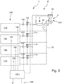
- FIG 2 is a simplified embodiment of the in Figure 1 temperature control system 1 shown.
- a vehicle battery 100 which consists of individual battery packs 102-108, is again provided.
- the temperature control system 1 in turn includes a central temperature control device 2, which includes a heating device 3 in the form of a high-voltage heater 30 and a cooling device 4 in the form of a CO 2 cooling circuit 400. Furthermore, a passive heat exchanger 50 is also provided.
- the structure of the CO 2 cooling circuit 400 corresponds to that which is already closed Figure 1 has been described as an example.
- the heating device 3 and the cooling device 4 act on the same temperature control medium circuit 52, so that either one, two, more or all of the separate battery packs 102-108 are heated by means of the central temperature control device 2 can be, or a cooling of one, two, more or all of the battery packs 102-108 can be achieved.
- a heating of at least one of the battery packs 102-108 and a simultaneous cooling of at least one other of the battery packs 102-108 cannot be achieved in this embodiment by the temperature control medium.
- the individual temperature control of the respective, separate battery packs 102-108 can be achieved by the individual circulation pumps 122 - 128, together with the simultaneous switching of the mixing valves 112-118, an individual temperature control medium supply to each individual battery pack 102- 108 can be achieved so that an individual temperature control of each battery pack can be achieved.
- the request for the respective temperature control output for heating or cooling the individual battery packs 102-108 can be carried out, for example, from a battery management system.
- a corresponding temperature that optimizes the overall performance of the vehicle battery 100 can thus be achieved individually in each of the battery packs 102-108.
- a battery management system is understood to mean a centralized or decentralized control device by means of which charging and discharging currents of a battery system can be controlled as a function of technical and physical parameters of individual battery cells, modules or packs.
- an individual temperature control of the battery packs 102-108 can be controlled or regulated by means of a controller 6, the controller 6 using temperature sensors 162-168 to provide information about the current temperature status of the respective battery packs 102-108 as well as information to the ambient temperature via an outside temperature sensor 169.
- the open-loop or closed-loop control 6 can then intervene in a controlling or regulating manner on the mixing valves 112-128 and circulating pumps 122-128 so that the desired temperature or a temperature within a predetermined temperature range is reached in each of the battery modules 102-108.
Landscapes
- Engineering & Computer Science (AREA)
- Manufacturing & Machinery (AREA)
- Chemical & Material Sciences (AREA)
- Chemical Kinetics & Catalysis (AREA)
- Electrochemistry (AREA)
- General Chemical & Material Sciences (AREA)
- Life Sciences & Earth Sciences (AREA)
- Sustainable Development (AREA)
- Sustainable Energy (AREA)
- Power Engineering (AREA)
- Transportation (AREA)
- Mechanical Engineering (AREA)
- Automation & Control Theory (AREA)
- Physics & Mathematics (AREA)
- Electromagnetism (AREA)
- Secondary Cells (AREA)
- Electric Propulsion And Braking For Vehicles (AREA)
Applications Claiming Priority (1)
| Application Number | Priority Date | Filing Date | Title |
|---|---|---|---|
| DE102018132177.5A DE102018132177B4 (de) | 2018-12-13 | 2018-12-13 | Temperierungssystem |
Publications (1)
| Publication Number | Publication Date |
|---|---|
| EP3756938A1 true EP3756938A1 (fr) | 2020-12-30 |
Family
ID=68917371
Family Applications (1)
| Application Number | Title | Priority Date | Filing Date |
|---|---|---|---|
| EP19216193.3A Pending EP3756938A1 (fr) | 2018-12-13 | 2019-12-13 | Système de thermorégulation |
Country Status (2)
| Country | Link |
|---|---|
| EP (1) | EP3756938A1 (fr) |
| DE (1) | DE102018132177B4 (fr) |
Families Citing this family (1)
| Publication number | Priority date | Publication date | Assignee | Title |
|---|---|---|---|---|
| CN218274761U (zh) * | 2022-07-15 | 2023-01-10 | 深圳英飞源技术有限公司 | 一种环路式热管理系统 |
Citations (9)
| Publication number | Priority date | Publication date | Assignee | Title |
|---|---|---|---|---|
| US20140227568A1 (en) * | 2013-02-09 | 2014-08-14 | Quantumscape Corporation | Battery system with selective thermal management |
| DE102014204263A1 (de) * | 2014-03-07 | 2015-09-10 | Magna Steyr Battery Systems Gmbh & Co Og | Batteriekühlsystem |
| DE102014210158A1 (de) * | 2014-05-28 | 2015-12-03 | Bayerische Motoren Werke Aktiengesellschaft | Fahrzeug mit einem elektrischen Energiespeicher, der ein Kühlkanalsystem aufweist sowie Verfahren zum Verringern der Gefahr, dass ein in einem Fahrzeug verbauter elektrischer Energiespeicher in Brand gerät |
| DE102014111517A1 (de) * | 2014-08-13 | 2016-02-18 | Dr. Ing. H.C. F. Porsche Aktiengesellschaft | Verfahren zum Betrieb eines Fahrzeugs und Fahrzeug |
| US20160118697A1 (en) * | 2010-02-03 | 2016-04-28 | Samsung Sdi Co., Ltd. | Battery system and driving method thereof |
| US20170005375A1 (en) | 2015-06-30 | 2017-01-05 | Proterra Inc. | Battery system cooling |
| US20170008419A1 (en) * | 2015-07-08 | 2017-01-12 | Atieva, Inc. | Method and Apparatus for Selectively Heating Individual Battery Modules Within a Battery Pack |
| DE102015215253A1 (de) * | 2015-08-11 | 2017-02-16 | Bayerische Motoren Werke Aktiengesellschaft | Kühlvorrichtung für Energiespeicher |
| EP3354499A1 (fr) * | 2017-01-25 | 2018-08-01 | Robert Bosch GmbH | Dispositif de chauffage d'une batterie de traction et procédé de fonctionnement d'une batterie de traction |
-
2018
- 2018-12-13 DE DE102018132177.5A patent/DE102018132177B4/de active Active
-
2019
- 2019-12-13 EP EP19216193.3A patent/EP3756938A1/fr active Pending
Patent Citations (9)
| Publication number | Priority date | Publication date | Assignee | Title |
|---|---|---|---|---|
| US20160118697A1 (en) * | 2010-02-03 | 2016-04-28 | Samsung Sdi Co., Ltd. | Battery system and driving method thereof |
| US20140227568A1 (en) * | 2013-02-09 | 2014-08-14 | Quantumscape Corporation | Battery system with selective thermal management |
| DE102014204263A1 (de) * | 2014-03-07 | 2015-09-10 | Magna Steyr Battery Systems Gmbh & Co Og | Batteriekühlsystem |
| DE102014210158A1 (de) * | 2014-05-28 | 2015-12-03 | Bayerische Motoren Werke Aktiengesellschaft | Fahrzeug mit einem elektrischen Energiespeicher, der ein Kühlkanalsystem aufweist sowie Verfahren zum Verringern der Gefahr, dass ein in einem Fahrzeug verbauter elektrischer Energiespeicher in Brand gerät |
| DE102014111517A1 (de) * | 2014-08-13 | 2016-02-18 | Dr. Ing. H.C. F. Porsche Aktiengesellschaft | Verfahren zum Betrieb eines Fahrzeugs und Fahrzeug |
| US20170005375A1 (en) | 2015-06-30 | 2017-01-05 | Proterra Inc. | Battery system cooling |
| US20170008419A1 (en) * | 2015-07-08 | 2017-01-12 | Atieva, Inc. | Method and Apparatus for Selectively Heating Individual Battery Modules Within a Battery Pack |
| DE102015215253A1 (de) * | 2015-08-11 | 2017-02-16 | Bayerische Motoren Werke Aktiengesellschaft | Kühlvorrichtung für Energiespeicher |
| EP3354499A1 (fr) * | 2017-01-25 | 2018-08-01 | Robert Bosch GmbH | Dispositif de chauffage d'une batterie de traction et procédé de fonctionnement d'une batterie de traction |
Also Published As
| Publication number | Publication date |
|---|---|
| DE102018132177A1 (de) | 2020-06-18 |
| DE102018132177B4 (de) | 2024-05-02 |
Similar Documents
| Publication | Publication Date | Title |
|---|---|---|
| EP3444135B1 (fr) | Système circulatoire pour un véhicule à pile à combustible | |
| DE112007002347B4 (de) | Klimatisierungssteuerungssystem | |
| DE102019110433A1 (de) | Wärmepumpensystem für ein Fahrzeug | |
| WO2015091969A1 (fr) | Gestion thermique pour un véhicule électrique ou hybride ainsi que procédé pour le conditionnement de l'habitacle d'un tel véhicule automobile | |
| DE102011076737A1 (de) | Vorrichtung zur Bereitstellung elektrischer Energie | |
| WO2011000826A1 (fr) | Procédé de refroidissement de blocs-batteries et bloc-batterie subdivisé en modules | |
| DE102012018057A1 (de) | Vorrichtung und Verfahren zum Temperieren einer Batterie | |
| WO2017092853A1 (fr) | Agencement de piles à combustible, procédé pour faire fonctionner un tel agencement de piles à combustible et utilisation d'un tel agencement de piles à combustible | |
| EP2442390B1 (fr) | Batterie dotée d'un risque d'incendie réduit | |
| DE102020129589A1 (de) | Vorrichtung zur Kontrolle der Batterietemperatur | |
| DE102018132177B4 (de) | Temperierungssystem | |
| DE102020007740A1 (de) | Temperiervorrichtung für ein Fahrzeug | |
| DE10152233A1 (de) | Brennstoffzellensystem | |
| WO2009040267A2 (fr) | Utilisation d'une batterie de véhicule | |
| DE102011006648A1 (de) | Energiespeichervorrichtung mit einem Solarzellenmodul und zugehöriges Betriebsverfahren | |
| DE102018205345B4 (de) | Elektromotor mit Flüssigkeitskühlung und Verwendung eines derartigen Elektromotors | |
| DE102018108003A1 (de) | Batteriemodul | |
| DE102015222713A1 (de) | Elektrizitätsstrang für ein Kraftfahrzeug | |
| WO2019170818A1 (fr) | Véhicule comprenant au moins un accumulateur d'énergie électrochimique | |
| DE102021209692B4 (de) | B[atterie]T[hermo]M[anagement]S[ystem] sowie Verfahren zum Regeln der Temperatur einer als Stromquelle für einen Elektromotor eines Kraftfahrzeugs ausgebildeten Batterie | |
| DE102021204382A1 (de) | Batterie mit einer Kühlvorrichtung und Kraftfahrzeug mit einer Batterie | |
| DE102022206698B4 (de) | Wärmeenergiesystem zum Regulieren von Temperaturen eines Fahrzeugs und Fahrzeug mit einem solchen | |
| DE102016015288A1 (de) | Temperiereinheit für eine Batterie | |
| WO2024003258A1 (fr) | Système d'énergie thermique pour réguler les températures d'un véhicule et véhicule équipé d'un tel système | |
| DE102022210956A1 (de) | Temperiersystem zum Temperieren einer Kraftfahrzeugbatterie |
Legal Events
| Date | Code | Title | Description |
|---|---|---|---|
| PUAI | Public reference made under article 153(3) epc to a published international application that has entered the european phase |
Free format text: ORIGINAL CODE: 0009012 |
|
| STAA | Information on the status of an ep patent application or granted ep patent |
Free format text: STATUS: THE APPLICATION HAS BEEN PUBLISHED |
|
| AK | Designated contracting states |
Kind code of ref document: A1 Designated state(s): AL AT BE BG CH CY CZ DE DK EE ES FI FR GB GR HR HU IE IS IT LI LT LU LV MC MK MT NL NO PL PT RO RS SE SI SK SM TR |
|
| AX | Request for extension of the european patent |
Extension state: BA ME |
|
| STAA | Information on the status of an ep patent application or granted ep patent |
Free format text: STATUS: REQUEST FOR EXAMINATION WAS MADE |
|
| 17P | Request for examination filed |
Effective date: 20210623 |
|
| RBV | Designated contracting states (corrected) |
Designated state(s): AL AT BE BG CH CY CZ DE DK EE ES FI FR GB GR HR HU IE IS IT LI LT LU LV MC MK MT NL NO PL PT RO RS SE SI SK SM TR |
|
| GRAP | Despatch of communication of intention to grant a patent |
Free format text: ORIGINAL CODE: EPIDOSNIGR1 |
|
| STAA | Information on the status of an ep patent application or granted ep patent |
Free format text: STATUS: GRANT OF PATENT IS INTENDED |
|
| RIC1 | Information provided on ipc code assigned before grant |
Ipc: H01M 10/63 20140101ALI20231206BHEP Ipc: H01M 10/663 20140101ALI20231206BHEP Ipc: H01M 10/6571 20140101ALI20231206BHEP Ipc: H01M 10/6568 20140101ALI20231206BHEP Ipc: H01M 10/625 20140101ALI20231206BHEP Ipc: H01M 10/615 20140101ALI20231206BHEP Ipc: H01M 10/613 20140101ALI20231206BHEP Ipc: H01M 10/48 20060101ALI20231206BHEP Ipc: B60L 58/24 20190101ALI20231206BHEP Ipc: B60L 58/18 20190101AFI20231206BHEP |
|
| INTG | Intention to grant announced |
Effective date: 20240104 |
|
| GRAS | Grant fee paid |
Free format text: ORIGINAL CODE: EPIDOSNIGR3 |
|
| GRAA | (expected) grant |
Free format text: ORIGINAL CODE: 0009210 |
|
| STAA | Information on the status of an ep patent application or granted ep patent |
Free format text: STATUS: THE PATENT HAS BEEN GRANTED |