EP3756795A1 - Gear shaft and method of manufacturing - Google Patents
Gear shaft and method of manufacturing Download PDFInfo
- Publication number
- EP3756795A1 EP3756795A1 EP19212730.6A EP19212730A EP3756795A1 EP 3756795 A1 EP3756795 A1 EP 3756795A1 EP 19212730 A EP19212730 A EP 19212730A EP 3756795 A1 EP3756795 A1 EP 3756795A1
- Authority
- EP
- European Patent Office
- Prior art keywords
- shaft
- transitioning
- gear shaft
- depositing
- ded
- Prior art date
- Legal status (The legal status is an assumption and is not a legal conclusion. Google has not performed a legal analysis and makes no representation as to the accuracy of the status listed.)
- Granted
Links
Images
Classifications
-
- B—PERFORMING OPERATIONS; TRANSPORTING
- B22—CASTING; POWDER METALLURGY
- B22F—WORKING METALLIC POWDER; MANUFACTURE OF ARTICLES FROM METALLIC POWDER; MAKING METALLIC POWDER; APPARATUS OR DEVICES SPECIALLY ADAPTED FOR METALLIC POWDER
- B22F5/00—Manufacture of workpieces or articles from metallic powder characterised by the special shape of the product
- B22F5/08—Manufacture of workpieces or articles from metallic powder characterised by the special shape of the product of toothed articles, e.g. gear wheels; of cam discs
-
- B—PERFORMING OPERATIONS; TRANSPORTING
- B22—CASTING; POWDER METALLURGY
- B22F—WORKING METALLIC POWDER; MANUFACTURE OF ARTICLES FROM METALLIC POWDER; MAKING METALLIC POWDER; APPARATUS OR DEVICES SPECIALLY ADAPTED FOR METALLIC POWDER
- B22F10/00—Additive manufacturing of workpieces or articles from metallic powder
- B22F10/20—Direct sintering or melting
-
- B—PERFORMING OPERATIONS; TRANSPORTING
- B22—CASTING; POWDER METALLURGY
- B22F—WORKING METALLIC POWDER; MANUFACTURE OF ARTICLES FROM METALLIC POWDER; MAKING METALLIC POWDER; APPARATUS OR DEVICES SPECIALLY ADAPTED FOR METALLIC POWDER
- B22F10/00—Additive manufacturing of workpieces or articles from metallic powder
- B22F10/20—Direct sintering or melting
- B22F10/25—Direct deposition of metal particles, e.g. direct metal deposition [DMD] or laser engineered net shaping [LENS]
-
- B—PERFORMING OPERATIONS; TRANSPORTING
- B22—CASTING; POWDER METALLURGY
- B22F—WORKING METALLIC POWDER; MANUFACTURE OF ARTICLES FROM METALLIC POWDER; MAKING METALLIC POWDER; APPARATUS OR DEVICES SPECIALLY ADAPTED FOR METALLIC POWDER
- B22F10/00—Additive manufacturing of workpieces or articles from metallic powder
- B22F10/60—Treatment of workpieces or articles after build-up
- B22F10/66—Treatment of workpieces or articles after build-up by mechanical means
-
- B—PERFORMING OPERATIONS; TRANSPORTING
- B33—ADDITIVE MANUFACTURING TECHNOLOGY
- B33Y—ADDITIVE MANUFACTURING, i.e. MANUFACTURING OF THREE-DIMENSIONAL [3D] OBJECTS BY ADDITIVE DEPOSITION, ADDITIVE AGGLOMERATION OR ADDITIVE LAYERING, e.g. BY 3D PRINTING, STEREOLITHOGRAPHY OR SELECTIVE LASER SINTERING
- B33Y10/00—Processes of additive manufacturing
-
- B—PERFORMING OPERATIONS; TRANSPORTING
- B33—ADDITIVE MANUFACTURING TECHNOLOGY
- B33Y—ADDITIVE MANUFACTURING, i.e. MANUFACTURING OF THREE-DIMENSIONAL [3D] OBJECTS BY ADDITIVE DEPOSITION, ADDITIVE AGGLOMERATION OR ADDITIVE LAYERING, e.g. BY 3D PRINTING, STEREOLITHOGRAPHY OR SELECTIVE LASER SINTERING
- B33Y80/00—Products made by additive manufacturing
-
- C—CHEMISTRY; METALLURGY
- C23—COATING METALLIC MATERIAL; COATING MATERIAL WITH METALLIC MATERIAL; CHEMICAL SURFACE TREATMENT; DIFFUSION TREATMENT OF METALLIC MATERIAL; COATING BY VACUUM EVAPORATION, BY SPUTTERING, BY ION IMPLANTATION OR BY CHEMICAL VAPOUR DEPOSITION, IN GENERAL; INHIBITING CORROSION OF METALLIC MATERIAL OR INCRUSTATION IN GENERAL
- C23C—COATING METALLIC MATERIAL; COATING MATERIAL WITH METALLIC MATERIAL; SURFACE TREATMENT OF METALLIC MATERIAL BY DIFFUSION INTO THE SURFACE, BY CHEMICAL CONVERSION OR SUBSTITUTION; COATING BY VACUUM EVAPORATION, BY SPUTTERING, BY ION IMPLANTATION OR BY CHEMICAL VAPOUR DEPOSITION, IN GENERAL
- C23C24/00—Coating starting from inorganic powder
-
- C—CHEMISTRY; METALLURGY
- C23—COATING METALLIC MATERIAL; COATING MATERIAL WITH METALLIC MATERIAL; CHEMICAL SURFACE TREATMENT; DIFFUSION TREATMENT OF METALLIC MATERIAL; COATING BY VACUUM EVAPORATION, BY SPUTTERING, BY ION IMPLANTATION OR BY CHEMICAL VAPOUR DEPOSITION, IN GENERAL; INHIBITING CORROSION OF METALLIC MATERIAL OR INCRUSTATION IN GENERAL
- C23C—COATING METALLIC MATERIAL; COATING MATERIAL WITH METALLIC MATERIAL; SURFACE TREATMENT OF METALLIC MATERIAL BY DIFFUSION INTO THE SURFACE, BY CHEMICAL CONVERSION OR SUBSTITUTION; COATING BY VACUUM EVAPORATION, BY SPUTTERING, BY ION IMPLANTATION OR BY CHEMICAL VAPOUR DEPOSITION, IN GENERAL
- C23C26/00—Coating not provided for in groups C23C2/00 - C23C24/00
-
- F—MECHANICAL ENGINEERING; LIGHTING; HEATING; WEAPONS; BLASTING
- F16—ENGINEERING ELEMENTS AND UNITS; GENERAL MEASURES FOR PRODUCING AND MAINTAINING EFFECTIVE FUNCTIONING OF MACHINES OR INSTALLATIONS; THERMAL INSULATION IN GENERAL
- F16C—SHAFTS; FLEXIBLE SHAFTS; ELEMENTS OR CRANKSHAFT MECHANISMS; ROTARY BODIES OTHER THAN GEARING ELEMENTS; BEARINGS
- F16C3/00—Shafts; Axles; Cranks; Eccentrics
- F16C3/02—Shafts; Axles
-
- F—MECHANICAL ENGINEERING; LIGHTING; HEATING; WEAPONS; BLASTING
- F16—ENGINEERING ELEMENTS AND UNITS; GENERAL MEASURES FOR PRODUCING AND MAINTAINING EFFECTIVE FUNCTIONING OF MACHINES OR INSTALLATIONS; THERMAL INSULATION IN GENERAL
- F16C—SHAFTS; FLEXIBLE SHAFTS; ELEMENTS OR CRANKSHAFT MECHANISMS; ROTARY BODIES OTHER THAN GEARING ELEMENTS; BEARINGS
- F16C3/00—Shafts; Axles; Cranks; Eccentrics
- F16C3/02—Shafts; Axles
- F16C3/023—Shafts; Axles made of several parts, e.g. by welding
-
- F—MECHANICAL ENGINEERING; LIGHTING; HEATING; WEAPONS; BLASTING
- F16—ENGINEERING ELEMENTS AND UNITS; GENERAL MEASURES FOR PRODUCING AND MAINTAINING EFFECTIVE FUNCTIONING OF MACHINES OR INSTALLATIONS; THERMAL INSULATION IN GENERAL
- F16H—GEARING
- F16H55/00—Elements with teeth or friction surfaces for conveying motion; Worms, pulleys or sheaves for gearing mechanisms
- F16H55/02—Toothed members; Worms
- F16H55/17—Toothed wheels
-
- F—MECHANICAL ENGINEERING; LIGHTING; HEATING; WEAPONS; BLASTING
- F16—ENGINEERING ELEMENTS AND UNITS; GENERAL MEASURES FOR PRODUCING AND MAINTAINING EFFECTIVE FUNCTIONING OF MACHINES OR INSTALLATIONS; THERMAL INSULATION IN GENERAL
- F16H—GEARING
- F16H57/00—General details of gearing
- F16H57/0018—Shaft assemblies for gearings
- F16H57/0025—Shaft assemblies for gearings with gearing elements rigidly connected to a shaft, e.g. securing gears or pulleys by specially adapted splines, keys or methods
-
- B—PERFORMING OPERATIONS; TRANSPORTING
- B22—CASTING; POWDER METALLURGY
- B22F—WORKING METALLIC POWDER; MANUFACTURE OF ARTICLES FROM METALLIC POWDER; MAKING METALLIC POWDER; APPARATUS OR DEVICES SPECIALLY ADAPTED FOR METALLIC POWDER
- B22F2999/00—Aspects linked to processes or compositions used in powder metallurgy
-
- F—MECHANICAL ENGINEERING; LIGHTING; HEATING; WEAPONS; BLASTING
- F16—ENGINEERING ELEMENTS AND UNITS; GENERAL MEASURES FOR PRODUCING AND MAINTAINING EFFECTIVE FUNCTIONING OF MACHINES OR INSTALLATIONS; THERMAL INSULATION IN GENERAL
- F16C—SHAFTS; FLEXIBLE SHAFTS; ELEMENTS OR CRANKSHAFT MECHANISMS; ROTARY BODIES OTHER THAN GEARING ELEMENTS; BEARINGS
- F16C2204/00—Metallic materials; Alloys
- F16C2204/20—Alloys based on aluminium
-
- F—MECHANICAL ENGINEERING; LIGHTING; HEATING; WEAPONS; BLASTING
- F16—ENGINEERING ELEMENTS AND UNITS; GENERAL MEASURES FOR PRODUCING AND MAINTAINING EFFECTIVE FUNCTIONING OF MACHINES OR INSTALLATIONS; THERMAL INSULATION IN GENERAL
- F16C—SHAFTS; FLEXIBLE SHAFTS; ELEMENTS OR CRANKSHAFT MECHANISMS; ROTARY BODIES OTHER THAN GEARING ELEMENTS; BEARINGS
- F16C2204/00—Metallic materials; Alloys
- F16C2204/40—Alloys based on refractory metals
- F16C2204/42—Alloys based on titanium
-
- F—MECHANICAL ENGINEERING; LIGHTING; HEATING; WEAPONS; BLASTING
- F16—ENGINEERING ELEMENTS AND UNITS; GENERAL MEASURES FOR PRODUCING AND MAINTAINING EFFECTIVE FUNCTIONING OF MACHINES OR INSTALLATIONS; THERMAL INSULATION IN GENERAL
- F16C—SHAFTS; FLEXIBLE SHAFTS; ELEMENTS OR CRANKSHAFT MECHANISMS; ROTARY BODIES OTHER THAN GEARING ELEMENTS; BEARINGS
- F16C2204/00—Metallic materials; Alloys
- F16C2204/52—Alloys based on nickel, e.g. Inconel
-
- F—MECHANICAL ENGINEERING; LIGHTING; HEATING; WEAPONS; BLASTING
- F16—ENGINEERING ELEMENTS AND UNITS; GENERAL MEASURES FOR PRODUCING AND MAINTAINING EFFECTIVE FUNCTIONING OF MACHINES OR INSTALLATIONS; THERMAL INSULATION IN GENERAL
- F16C—SHAFTS; FLEXIBLE SHAFTS; ELEMENTS OR CRANKSHAFT MECHANISMS; ROTARY BODIES OTHER THAN GEARING ELEMENTS; BEARINGS
- F16C2204/00—Metallic materials; Alloys
- F16C2204/60—Ferrous alloys, e.g. steel alloys
-
- F—MECHANICAL ENGINEERING; LIGHTING; HEATING; WEAPONS; BLASTING
- F16—ENGINEERING ELEMENTS AND UNITS; GENERAL MEASURES FOR PRODUCING AND MAINTAINING EFFECTIVE FUNCTIONING OF MACHINES OR INSTALLATIONS; THERMAL INSULATION IN GENERAL
- F16C—SHAFTS; FLEXIBLE SHAFTS; ELEMENTS OR CRANKSHAFT MECHANISMS; ROTARY BODIES OTHER THAN GEARING ELEMENTS; BEARINGS
- F16C2220/00—Shaping
-
- F—MECHANICAL ENGINEERING; LIGHTING; HEATING; WEAPONS; BLASTING
- F16—ENGINEERING ELEMENTS AND UNITS; GENERAL MEASURES FOR PRODUCING AND MAINTAINING EFFECTIVE FUNCTIONING OF MACHINES OR INSTALLATIONS; THERMAL INSULATION IN GENERAL
- F16C—SHAFTS; FLEXIBLE SHAFTS; ELEMENTS OR CRANKSHAFT MECHANISMS; ROTARY BODIES OTHER THAN GEARING ELEMENTS; BEARINGS
- F16C2361/00—Apparatus or articles in engineering in general
- F16C2361/61—Toothed gear systems, e.g. support of pinion shafts
-
- Y—GENERAL TAGGING OF NEW TECHNOLOGICAL DEVELOPMENTS; GENERAL TAGGING OF CROSS-SECTIONAL TECHNOLOGIES SPANNING OVER SEVERAL SECTIONS OF THE IPC; TECHNICAL SUBJECTS COVERED BY FORMER USPC CROSS-REFERENCE ART COLLECTIONS [XRACs] AND DIGESTS
- Y02—TECHNOLOGIES OR APPLICATIONS FOR MITIGATION OR ADAPTATION AGAINST CLIMATE CHANGE
- Y02P—CLIMATE CHANGE MITIGATION TECHNOLOGIES IN THE PRODUCTION OR PROCESSING OF GOODS
- Y02P10/00—Technologies related to metal processing
- Y02P10/25—Process efficiency
Definitions
- the present disclosure relates to gear shaft manufacturing, and more particularly to gear manufacturing using directed energy deposition.
- gear shafts are manufactured using welding to complete an assembled product. Gears of various materials are required to operate in certain environmental conditions. Welding operation is complex and costly.
- a method of manufacturing a gear shaft includes depositing only a first material via directed energy deposition (DED), forming a first portion of the gear shaft via the depositing only the first material via directed energy deposition (DED), forming a transitioning portion of the gear shaft via depositing of a varying ratio of the first material with a second material via DED, and forming a second portion of the gear shaft via the depositing via DED of only the second material.
- the shaft can be manufactured by a continuous process and be machined a final dimension of the first portion, the second portion, or the transitioning portion.
- Forming the transitioning portion can include a single build direction from the first portion to the second portion.
- Forming the first portion can include depositing the first material in powder or wire form.
- a gear shaft includes a first portion including only a first material, a second portion including only a second material, a transitioning portion, attached to both the first portion and the second portion, including a varying ratio of the first material to the second material along a length of the transitioning portion.
- the transitioning portion can include a lengthwise majority of the shaft.
- the transitioning portion can include a gradient of the first material and a gradient of the second material there through.
- the gradient can be constant, stepped, or exponential.
- the first material can include a higher magnetic property than the second material.
- the first material can also include a higher coefficient of thermal expansion than the second material.
- the second material can include a second melting point and/or softening temperature and/or a second shear strength that is less than a first melting point and/or softening temperature and/or a first shear strength of the first material.
- the materials include titanium, aluminum, nickel or steel.
- the amount of the first material can change at approximately 5% per millimeter over the length of the shaft portion and the amount of second material also changes at a rate of approximately 5% per millimeter over the length of the shaft.
- the first amount of the first material is different from the first amount of the second material.
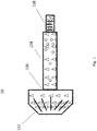
- Fig. 1 is a side view of a gear shaft showing an increasing amount of a first material in a first along a length thereof and decreasing amount of a second material along the length thereof.
- Fig. 1 a partial view of an exemplary embodiment of a gear shaft in accordance with the disclosure is shown in Fig. 1 and is designated generally by reference character 100.
- the methods and systems of the disclosure can be used to simplify production of gear shafts, while providing safer manufacturing techniques and requiring less energy, and enabling gear assemblies that contain materials with mechanical properties very specific and tailored to the application.
- Fig. 1 shows a gear shaft 100 produced by directed energy deposition, the additive process in which metal wire or powder is deposited in a layer by layer manner to produce a near net shape final component.
- a first portion 102 of the gear shaft is formed by depositing on a baseplate a first amount of a first material by directed energy deposition (DED) using a powder or wire as a source of the material wherein the first portion includes only the first material, forming a transitioning portion 104, attached to the first portion 102, by depositing a varying amount of the first material by DED and a varying amount of a second material by DED on an end 106 of the first portion 102 wherein the transition portion 104 includes a mixtures of the first and second materials and forming a second portion of the gear shaft, attached to the transitioning portion, by DED, wherein the second portion 108 includes a second amount of the second material wherein the second portion 108 includes only the second material.
- the shaft 100 is manufactured by a continuous process and the outer surface can
- the gear shaft 100 includes a bevel gear 102 configured to be used in a harsh operating environment, including a first amount of a first material
- the transition portion 104, attached to the bevel gear 102 includes a decreasing amount of the first material along a length of the gear shaft and a second material wherein the amount of the second material increases along the length of the gear shaft, and a second end, the second end 108 being a output gear shaft section attached to the transitioning portion 104, wherein the second portion includes a second amount of the second material.
- a gradient provides properties for optimal performance in distinct system environments, while entirely reducing the need for a complex joining operation.
- the transitioning portion 104 includes a lengthwise majority of the shaft 104.
- the transitioning portion 104 includes a gradient of the first material and a gradient of the second material therethrough.
- the gradient can be constant, be stepped, or be exponential, depending on application requirements.
- the first material includes a different magnetic property than the second material and a different coefficient of thermal expansion than the second material.
- the second material includes a second melting point and/or softening temperature and/or a second shear strength that is different than a first melting point and/or softening temperature and/or a first shear strength of the first material.
- the materials include titanium, aluminum, nickel or steel.
- the amount of the first material can change at approximately 5% per millimeter over the length of the shaft 100 and the amount of second material also changes at a rate of approximately 5% per millimeter over the length of the shaft 100 as well. This transition rate ensures this shaft will be able to withstand both structural and thermal loads.
- Traditional methods have produced gear shafts including a definitive border between a first material and the second material, which result in a shorter time between failures and increased risk of defects related to joining methods
Landscapes
- Engineering & Computer Science (AREA)
- Chemical & Material Sciences (AREA)
- General Engineering & Computer Science (AREA)
- Materials Engineering (AREA)
- Manufacturing & Machinery (AREA)
- Mechanical Engineering (AREA)
- Ocean & Marine Engineering (AREA)
- Organic Chemistry (AREA)
- Metallurgy (AREA)
- Chemical Kinetics & Catalysis (AREA)
- Gears, Cams (AREA)
- Powder Metallurgy (AREA)
- Laser Beam Processing (AREA)
Abstract
Description
- The present disclosure relates to gear shaft manufacturing, and more particularly to gear manufacturing using directed energy deposition.
- Traditionally gear shafts are manufactured using welding to complete an assembled product. Gears of various materials are required to operate in certain environmental conditions. Welding operation is complex and costly.
- Thus, there is a need in the art to eliminate the need for welding of gear shafts in order to reduce cost and lead time for manufacture of gear assemblies while providing increase performance, life, and reliability of gear components. The present disclosure may provide a solution for at least one of these challenges.
- A method of manufacturing a gear shaft includes depositing only a first material via directed energy deposition (DED), forming a first portion of the gear shaft via the depositing only the first material via directed energy deposition (DED), forming a transitioning portion of the gear shaft via depositing of a varying ratio of the first material with a second material via DED, and forming a second portion of the gear shaft via the depositing via DED of only the second material. The shaft can be manufactured by a continuous process and be machined a final dimension of the first portion, the second portion, or the transitioning portion.
- Forming the transitioning portion can include a single build direction from the first portion to the second portion. Forming the first portion can include depositing the first material in powder or wire form.
- A gear shaft includes a first portion including only a first material, a second portion including only a second material, a transitioning portion, attached to both the first portion and the second portion, including a varying ratio of the first material to the second material along a length of the transitioning portion.
- The transitioning portion can include a lengthwise majority of the shaft. The transitioning portion can include a gradient of the first material and a gradient of the second material there through. The gradient can be constant, stepped, or exponential.
- The first material can include a higher magnetic property than the second material. The first material can also include a higher coefficient of thermal expansion than the second material. The second material can include a second melting point and/or softening temperature and/or a second shear strength that is less than a first melting point and/or softening temperature and/or a first shear strength of the first material. The materials include titanium, aluminum, nickel or steel.
- The amount of the first material can change at approximately 5% per millimeter over the length of the shaft portion and the amount of second material also changes at a rate of approximately 5% per millimeter over the length of the shaft. The first amount of the first material is different from the first amount of the second material.
- These and other features of the systems and methods of the subject disclosure will become more readily apparent to those skilled in the art from the following detailed description of the preferred embodiments taken in conjunction with the drawings.
- So that those skilled in the art to which the subject disclosure appertains will readily understand how to make and use the devices and methods of the subject disclosure without undue experimentation, preferred embodiments thereof will be described in detail herein below by way of example only and with reference to certain figures, wherein:
Fig. 1 is a side view of a gear shaft showing an increasing amount of a first material in a first along a length thereof and decreasing amount of a second material along the length thereof. - Reference will now be made to the drawings wherein like reference numerals identify similar structural features or aspects of the subject disclosure. For purposes of explanation and illustration, and not limitation, a partial view of an exemplary embodiment of a gear shaft in accordance with the disclosure is shown in
Fig. 1 and is designated generally byreference character 100. The methods and systems of the disclosure can be used to simplify production of gear shafts, while providing safer manufacturing techniques and requiring less energy, and enabling gear assemblies that contain materials with mechanical properties very specific and tailored to the application. -
Fig. 1 , shows agear shaft 100 produced by directed energy deposition, the additive process in which metal wire or powder is deposited in a layer by layer manner to produce a near net shape final component. Afirst portion 102 of the gear shaft is formed by depositing on a baseplate a first amount of a first material by directed energy deposition (DED) using a powder or wire as a source of the material wherein the first portion includes only the first material, forming atransitioning portion 104, attached to thefirst portion 102, by depositing a varying amount of the first material by DED and a varying amount of a second material by DED on anend 106 of thefirst portion 102 wherein thetransition portion 104 includes a mixtures of the first and second materials and forming a second portion of the gear shaft, attached to the transitioning portion, by DED, wherein thesecond portion 108 includes a second amount of the second material wherein thesecond portion 108 includes only the second material. Theshaft 100 is manufactured by a continuous process and the outer surface can later be machined to a final dimension. Forming thetransitioning portion 104 includes a single build direction from thefirst portion 102 to thesecond portion 108. - Referring again to
Fig. 1 , thegear shaft 100 includes abevel gear 102 configured to be used in a harsh operating environment, including a first amount of a first material, thetransition portion 104, attached to thebevel gear 102, includes a decreasing amount of the first material along a length of the gear shaft and a second material wherein the amount of the second material increases along the length of the gear shaft, and a second end, thesecond end 108 being a output gear shaft section attached to thetransitioning portion 104, wherein the second portion includes a second amount of the second material. A gradient provides properties for optimal performance in distinct system environments, while entirely reducing the need for a complex joining operation. - As show in in
Fig. 1 , thetransitioning portion 104 includes a lengthwise majority of theshaft 104. Thetransitioning portion 104 includes a gradient of the first material and a gradient of the second material therethrough. The gradient can be constant, be stepped, or be exponential, depending on application requirements. The first material includes a different magnetic property than the second material and a different coefficient of thermal expansion than the second material. The second material includes a second melting point and/or softening temperature and/or a second shear strength that is different than a first melting point and/or softening temperature and/or a first shear strength of the first material. The materials include titanium, aluminum, nickel or steel. The amount of the first material can change at approximately 5% per millimeter over the length of theshaft 100 and the amount of second material also changes at a rate of approximately 5% per millimeter over the length of theshaft 100 as well. This transition rate ensures this shaft will be able to withstand both structural and thermal loads. Traditional methods have produced gear shafts including a definitive border between a first material and the second material, which result in a shorter time between failures and increased risk of defects related to joining methods - The methods and systems of the present disclosure, as described above and shown in the drawings, provide for gear shaft with superior properties including increased reliability and stability, and/ cost. While the apparatus and methods of the subject disclosure have been shown and described with reference to embodiments, those skilled in the art will readily appreciate that changes and/or modifications may be made thereto without departing from the spirit and score of the subject disclosure.
Claims (15)
- A method of manufacturing a gear shaft (100) comprising:depositing only a first material via directed energy deposition (DED);forming a first portion (102) of the gear shaft via the depositing only the first material via directed energy deposition (DED);forming a transitioning portion (104) of the gear shaft via depositing of a varying ratio of
the first material with a second material via DED; andforming a second portion (108) of the gear shaft via the depositing via DED of only the second material. - The method of claim 1, wherein the shaft is manufactured by a continuous process.
- The method of any preceding claim, further comprising machining an outer surface to a final dimension of the first portion, the second portion, or the transitioning portion.
- The method of any preceding claim, wherein forming the transitioning portion includes a single build direction from the first portion to the second portion.
- The method of any preceding claim, wherein forming the first portion includes depositing the first material in powder or wire form.
- A gear shaft (100) comprising:a first portion (102) including only a first material;a second portion (108) including only a second material; anda transitioning portion (104), attached to both the first portion and the second portion, including a varying ratio of the first material to the second material along a length of the transitioning portion.
- The shaft of claim 6, wherein the transitioning portion includes a lengthwise majority of the shaft.
- The shaft of claim 6 or 7, wherein the transitioning portion includes a gradient of the first material and a gradient of the second material there through.
- The shaft of claim 6, 7 or 8, wherein the gradient of the first material is 5% per millimeter; and/or wherein the gradient of the second material is 5% per millimeter.
- The shaft of any of claims 6 to 9, wherein the gradient is constant, stepped, or exponential.
- The shaft of any of claims 6 to 10, wherein the first material includes a higher magnetic property than the second material.
- The shaft of any of claims 6 to 11, wherein the first material includes a higher coefficient of thermal expansion than the second material.
- The shaft of any of claims 6 to 12, wherein the second material includes a second melting point and/or softening temperature and/or a second shear strength that is less than a first melting point and/or softening temperature and/or a first shear strength of the first material.
- The shaft of any of claims 6 to 13, wherein the materials include titanium, aluminum, nickel or steel.
- The shaft of any of claims 6 to 14, wherein the first amount of the first material is different from the first amount of the second material.
Applications Claiming Priority (1)
| Application Number | Priority Date | Filing Date | Title |
|---|---|---|---|
| US16/450,664 US11220751B2 (en) | 2019-06-24 | 2019-06-24 | Gear shaft and method of manufacturing |
Publications (2)
| Publication Number | Publication Date |
|---|---|
| EP3756795A1 true EP3756795A1 (en) | 2020-12-30 |
| EP3756795B1 EP3756795B1 (en) | 2023-03-29 |
Family
ID=68762502
Family Applications (1)
| Application Number | Title | Priority Date | Filing Date |
|---|---|---|---|
| EP19212730.6A Active EP3756795B1 (en) | 2019-06-24 | 2019-11-29 | Gear shaft and method of manufacturing |
Country Status (2)
| Country | Link |
|---|---|
| US (2) | US11220751B2 (en) |
| EP (1) | EP3756795B1 (en) |
Families Citing this family (1)
| Publication number | Priority date | Publication date | Assignee | Title |
|---|---|---|---|---|
| US12078234B2 (en) * | 2021-09-22 | 2024-09-03 | Beijing Institute Of Technology | Lightweight high load-bearing reducer and method for generating bionic bone structure of gear thereof |
Citations (3)
| Publication number | Priority date | Publication date | Assignee | Title |
|---|---|---|---|---|
| US20150323053A1 (en) * | 2013-01-28 | 2015-11-12 | United Technology Corporation | Structured material alloy component fabrication |
| US20170261087A1 (en) * | 2016-03-11 | 2017-09-14 | Deere & Company | Composite gears and methods of manufacturing such gears |
| US20180080503A1 (en) * | 2016-09-22 | 2018-03-22 | Goodrich Corporation | Bi-metal joints in shafts and couplings |
Family Cites Families (2)
| Publication number | Priority date | Publication date | Assignee | Title |
|---|---|---|---|---|
| US9700957B1 (en) * | 2014-09-25 | 2017-07-11 | Steven P. Burgess | Methods of fabricating reduced weight components |
| US10982710B2 (en) * | 2017-04-13 | 2021-04-20 | Hamilton Sundstrand Corporation | Shaft disconnects |
-
2019
- 2019-06-24 US US16/450,664 patent/US11220751B2/en not_active Expired - Fee Related
- 2019-11-29 EP EP19212730.6A patent/EP3756795B1/en active Active
-
2021
- 2021-12-08 US US17/545,879 patent/US11654486B2/en active Active
Patent Citations (3)
| Publication number | Priority date | Publication date | Assignee | Title |
|---|---|---|---|---|
| US20150323053A1 (en) * | 2013-01-28 | 2015-11-12 | United Technology Corporation | Structured material alloy component fabrication |
| US20170261087A1 (en) * | 2016-03-11 | 2017-09-14 | Deere & Company | Composite gears and methods of manufacturing such gears |
| US20180080503A1 (en) * | 2016-09-22 | 2018-03-22 | Goodrich Corporation | Bi-metal joints in shafts and couplings |
Non-Patent Citations (1)
| Title |
|---|
| CHOI S H ET AL: "A topological hierarchy-based approach to layered manufacturing of functionally graded multi-material objects", COMPUTERS IN INDUSTRY, ELSEVIER, AMSTERDAM, NL, vol. 60, no. 5, 1 June 2009 (2009-06-01), pages 349 - 363, XP026022586, ISSN: 0166-3615, [retrieved on 20090228], DOI: 10.1016/J.COMPIND.2009.01.008 * |
Also Published As
| Publication number | Publication date |
|---|---|
| US20200399764A1 (en) | 2020-12-24 |
| US20220136112A1 (en) | 2022-05-05 |
| US11654486B2 (en) | 2023-05-23 |
| US11220751B2 (en) | 2022-01-11 |
| EP3756795B1 (en) | 2023-03-29 |
Similar Documents
| Publication | Publication Date | Title |
|---|---|---|
| US20170356494A1 (en) | Plain Bearing And Method For Producing The Same | |
| US5096037A (en) | Gearshifting or sliding sleeve for automobile transmissions and a manufacturing process | |
| EP2942131B1 (en) | Seal, method for producing a gasket and flow engine | |
| DE102012004293B4 (en) | Manufacturing method of a squirrel cage rotor of an induction motor, wherein an end ring is soldered to a rod | |
| EP3696296B1 (en) | Structured material alloy component fabrication | |
| EP3468740B1 (en) | Method of joining materials using a grid structure achieved by additive manufacturing | |
| CN104864067B (en) | The face gear and its implementation of a kind of hierarchy | |
| EP0123702A1 (en) | Method of joining metallic work pieces | |
| US11654486B2 (en) | Gear shaft and method of manufacturing | |
| WO2011121808A1 (en) | Sliding member and method of manufacturing same | |
| JP2014008518A (en) | Method of manufacturing metal component, and metal component obtained by the manufacturing method | |
| JP2014530766A (en) | How to make multi-material gear | |
| EP0303606B1 (en) | Synchronisation ring | |
| DE602004003114T2 (en) | Method for producing an article from a fiber-reinforced composite metal | |
| EP2917165B1 (en) | Assembly comprising two ceramic bodies joined to one another, in particular a pressure measuring cell, and method for joining ceramic bodies by means of an active hard solder | |
| US20160186332A1 (en) | Pipe connector and method | |
| WO2020054569A1 (en) | Joined article lamination molding method and joining member | |
| CN107538008A (en) | A kind of new different metal materials combination interface structure and its manufacture method | |
| CN104907767A (en) | Method for producing a component | |
| WO2021121863A1 (en) | Joining two components of a field device for processing and automation technology | |
| DE102006009749A1 (en) | target arrangement | |
| EP0741116A1 (en) | Process for manufacturing of components with high thermal load capability | |
| WO2019149430A1 (en) | Short-circuit ring for connecting to cage bars | |
| DE1646989B1 (en) | VACUUM-TIGHT CONNECTION BETWEEN A CARAMIC TUBE AND A DISC-SHAPED METAL PART OF AN ELECTRIC DISCHARGE CONTAINER | |
| US20190321887A1 (en) | Stress relief for additive layer manufacturing |
Legal Events
| Date | Code | Title | Description |
|---|---|---|---|
| PUAI | Public reference made under article 153(3) epc to a published international application that has entered the european phase |
Free format text: ORIGINAL CODE: 0009012 |
|
| STAA | Information on the status of an ep patent application or granted ep patent |
Free format text: STATUS: THE APPLICATION HAS BEEN PUBLISHED |
|
| AK | Designated contracting states |
Kind code of ref document: A1 Designated state(s): AL AT BE BG CH CY CZ DE DK EE ES FI FR GB GR HR HU IE IS IT LI LT LU LV MC MK MT NL NO PL PT RO RS SE SI SK SM TR |
|
| AX | Request for extension of the european patent |
Extension state: BA ME |
|
| STAA | Information on the status of an ep patent application or granted ep patent |
Free format text: STATUS: REQUEST FOR EXAMINATION WAS MADE |
|
| 17P | Request for examination filed |
Effective date: 20210630 |
|
| RBV | Designated contracting states (corrected) |
Designated state(s): AL AT BE BG CH CY CZ DE DK EE ES FI FR GB GR HR HU IE IS IT LI LT LU LV MC MK MT NL NO PL PT RO RS SE SI SK SM TR |
|
| REG | Reference to a national code |
Ref country code: DE Ref legal event code: R079 Ref document number: 602019026854 Country of ref document: DE Free format text: PREVIOUS MAIN CLASS: B22F0003105000 Ipc: B22F0005080000 |
|
| GRAP | Despatch of communication of intention to grant a patent |
Free format text: ORIGINAL CODE: EPIDOSNIGR1 |
|
| STAA | Information on the status of an ep patent application or granted ep patent |
Free format text: STATUS: GRANT OF PATENT IS INTENDED |
|
| RIC1 | Information provided on ipc code assigned before grant |
Ipc: B22F 10/66 20210101ALI20220927BHEP Ipc: B22F 10/25 20210101ALI20220927BHEP Ipc: F16C 3/02 20060101ALI20220927BHEP Ipc: B22F 3/105 20060101ALI20220927BHEP Ipc: B33Y 80/00 20150101ALI20220927BHEP Ipc: B33Y 10/00 20150101ALI20220927BHEP Ipc: B22F 5/08 20060101AFI20220927BHEP |
|
| INTG | Intention to grant announced |
Effective date: 20221017 |
|
| GRAS | Grant fee paid |
Free format text: ORIGINAL CODE: EPIDOSNIGR3 |
|
| GRAA | (expected) grant |
Free format text: ORIGINAL CODE: 0009210 |
|
| STAA | Information on the status of an ep patent application or granted ep patent |
Free format text: STATUS: THE PATENT HAS BEEN GRANTED |
|
| AK | Designated contracting states |
Kind code of ref document: B1 Designated state(s): AL AT BE BG CH CY CZ DE DK EE ES FI FR GB GR HR HU IE IS IT LI LT LU LV MC MK MT NL NO PL PT RO RS SE SI SK SM TR |
|
| REG | Reference to a national code |
Ref country code: CH Ref legal event code: EP |
|
| REG | Reference to a national code |
Ref country code: DE Ref legal event code: R096 Ref document number: 602019026854 Country of ref document: DE |
|
| REG | Reference to a national code |
Ref country code: AT Ref legal event code: REF Ref document number: 1556317 Country of ref document: AT Kind code of ref document: T Effective date: 20230415 |
|
| REG | Reference to a national code |
Ref country code: IE Ref legal event code: FG4D |
|
| REG | Reference to a national code |
Ref country code: LT Ref legal event code: MG9D |
|
| P01 | Opt-out of the competence of the unified patent court (upc) registered |
Effective date: 20230603 |
|
| PG25 | Lapsed in a contracting state [announced via postgrant information from national office to epo] |
Ref country code: RS Free format text: LAPSE BECAUSE OF FAILURE TO SUBMIT A TRANSLATION OF THE DESCRIPTION OR TO PAY THE FEE WITHIN THE PRESCRIBED TIME-LIMIT Effective date: 20230329 Ref country code: NO Free format text: LAPSE BECAUSE OF FAILURE TO SUBMIT A TRANSLATION OF THE DESCRIPTION OR TO PAY THE FEE WITHIN THE PRESCRIBED TIME-LIMIT Effective date: 20230629 Ref country code: LV Free format text: LAPSE BECAUSE OF FAILURE TO SUBMIT A TRANSLATION OF THE DESCRIPTION OR TO PAY THE FEE WITHIN THE PRESCRIBED TIME-LIMIT Effective date: 20230329 Ref country code: LT Free format text: LAPSE BECAUSE OF FAILURE TO SUBMIT A TRANSLATION OF THE DESCRIPTION OR TO PAY THE FEE WITHIN THE PRESCRIBED TIME-LIMIT Effective date: 20230329 Ref country code: HR Free format text: LAPSE BECAUSE OF FAILURE TO SUBMIT A TRANSLATION OF THE DESCRIPTION OR TO PAY THE FEE WITHIN THE PRESCRIBED TIME-LIMIT Effective date: 20230329 |
|
| REG | Reference to a national code |
Ref country code: NL Ref legal event code: MP Effective date: 20230329 |
|
| REG | Reference to a national code |
Ref country code: AT Ref legal event code: MK05 Ref document number: 1556317 Country of ref document: AT Kind code of ref document: T Effective date: 20230329 |
|
| PG25 | Lapsed in a contracting state [announced via postgrant information from national office to epo] |
Ref country code: SE Free format text: LAPSE BECAUSE OF FAILURE TO SUBMIT A TRANSLATION OF THE DESCRIPTION OR TO PAY THE FEE WITHIN THE PRESCRIBED TIME-LIMIT Effective date: 20230329 Ref country code: NL Free format text: LAPSE BECAUSE OF FAILURE TO SUBMIT A TRANSLATION OF THE DESCRIPTION OR TO PAY THE FEE WITHIN THE PRESCRIBED TIME-LIMIT Effective date: 20230329 Ref country code: GR Free format text: LAPSE BECAUSE OF FAILURE TO SUBMIT A TRANSLATION OF THE DESCRIPTION OR TO PAY THE FEE WITHIN THE PRESCRIBED TIME-LIMIT Effective date: 20230630 Ref country code: FI Free format text: LAPSE BECAUSE OF FAILURE TO SUBMIT A TRANSLATION OF THE DESCRIPTION OR TO PAY THE FEE WITHIN THE PRESCRIBED TIME-LIMIT Effective date: 20230329 |
|
| PG25 | Lapsed in a contracting state [announced via postgrant information from national office to epo] |
Ref country code: SM Free format text: LAPSE BECAUSE OF FAILURE TO SUBMIT A TRANSLATION OF THE DESCRIPTION OR TO PAY THE FEE WITHIN THE PRESCRIBED TIME-LIMIT Effective date: 20230329 Ref country code: RO Free format text: LAPSE BECAUSE OF FAILURE TO SUBMIT A TRANSLATION OF THE DESCRIPTION OR TO PAY THE FEE WITHIN THE PRESCRIBED TIME-LIMIT Effective date: 20230329 Ref country code: PT Free format text: LAPSE BECAUSE OF FAILURE TO SUBMIT A TRANSLATION OF THE DESCRIPTION OR TO PAY THE FEE WITHIN THE PRESCRIBED TIME-LIMIT Effective date: 20230731 Ref country code: ES Free format text: LAPSE BECAUSE OF FAILURE TO SUBMIT A TRANSLATION OF THE DESCRIPTION OR TO PAY THE FEE WITHIN THE PRESCRIBED TIME-LIMIT Effective date: 20230329 Ref country code: EE Free format text: LAPSE BECAUSE OF FAILURE TO SUBMIT A TRANSLATION OF THE DESCRIPTION OR TO PAY THE FEE WITHIN THE PRESCRIBED TIME-LIMIT Effective date: 20230329 Ref country code: AT Free format text: LAPSE BECAUSE OF FAILURE TO SUBMIT A TRANSLATION OF THE DESCRIPTION OR TO PAY THE FEE WITHIN THE PRESCRIBED TIME-LIMIT Effective date: 20230329 |
|
| PG25 | Lapsed in a contracting state [announced via postgrant information from national office to epo] |
Ref country code: SK Free format text: LAPSE BECAUSE OF FAILURE TO SUBMIT A TRANSLATION OF THE DESCRIPTION OR TO PAY THE FEE WITHIN THE PRESCRIBED TIME-LIMIT Effective date: 20230329 Ref country code: PL Free format text: LAPSE BECAUSE OF FAILURE TO SUBMIT A TRANSLATION OF THE DESCRIPTION OR TO PAY THE FEE WITHIN THE PRESCRIBED TIME-LIMIT Effective date: 20230329 Ref country code: IS Free format text: LAPSE BECAUSE OF FAILURE TO SUBMIT A TRANSLATION OF THE DESCRIPTION OR TO PAY THE FEE WITHIN THE PRESCRIBED TIME-LIMIT Effective date: 20230729 |
|
| REG | Reference to a national code |
Ref country code: DE Ref legal event code: R097 Ref document number: 602019026854 Country of ref document: DE |
|
| PGFP | Annual fee paid to national office [announced via postgrant information from national office to epo] |
Ref country code: GB Payment date: 20231019 Year of fee payment: 5 |
|
| PG25 | Lapsed in a contracting state [announced via postgrant information from national office to epo] |
Ref country code: DK Free format text: LAPSE BECAUSE OF FAILURE TO SUBMIT A TRANSLATION OF THE DESCRIPTION OR TO PAY THE FEE WITHIN THE PRESCRIBED TIME-LIMIT Effective date: 20230329 Ref country code: CZ Free format text: LAPSE BECAUSE OF FAILURE TO SUBMIT A TRANSLATION OF THE DESCRIPTION OR TO PAY THE FEE WITHIN THE PRESCRIBED TIME-LIMIT Effective date: 20230329 |
|
| PGFP | Annual fee paid to national office [announced via postgrant information from national office to epo] |
Ref country code: FR Payment date: 20231019 Year of fee payment: 5 Ref country code: DE Payment date: 20231019 Year of fee payment: 5 |
|
| PLBE | No opposition filed within time limit |
Free format text: ORIGINAL CODE: 0009261 |
|
| STAA | Information on the status of an ep patent application or granted ep patent |
Free format text: STATUS: NO OPPOSITION FILED WITHIN TIME LIMIT |
|
| 26N | No opposition filed |
Effective date: 20240103 |
|
| PG25 | Lapsed in a contracting state [announced via postgrant information from national office to epo] |
Ref country code: SI Free format text: LAPSE BECAUSE OF FAILURE TO SUBMIT A TRANSLATION OF THE DESCRIPTION OR TO PAY THE FEE WITHIN THE PRESCRIBED TIME-LIMIT Effective date: 20230329 |
|
| PG25 | Lapsed in a contracting state [announced via postgrant information from national office to epo] |
Ref country code: SI Free format text: LAPSE BECAUSE OF FAILURE TO SUBMIT A TRANSLATION OF THE DESCRIPTION OR TO PAY THE FEE WITHIN THE PRESCRIBED TIME-LIMIT Effective date: 20230329 Ref country code: IT Free format text: LAPSE BECAUSE OF FAILURE TO SUBMIT A TRANSLATION OF THE DESCRIPTION OR TO PAY THE FEE WITHIN THE PRESCRIBED TIME-LIMIT Effective date: 20230329 |
|
| REG | Reference to a national code |
Ref country code: CH Ref legal event code: PL |
|
| PG25 | Lapsed in a contracting state [announced via postgrant information from national office to epo] |
Ref country code: MC Free format text: LAPSE BECAUSE OF FAILURE TO SUBMIT A TRANSLATION OF THE DESCRIPTION OR TO PAY THE FEE WITHIN THE PRESCRIBED TIME-LIMIT Effective date: 20230329 |
|
| PG25 | Lapsed in a contracting state [announced via postgrant information from national office to epo] |
Ref country code: LU Free format text: LAPSE BECAUSE OF NON-PAYMENT OF DUE FEES Effective date: 20231129 |
|
| PG25 | Lapsed in a contracting state [announced via postgrant information from national office to epo] |
Ref country code: CH Free format text: LAPSE BECAUSE OF NON-PAYMENT OF DUE FEES Effective date: 20231130 |
|
| PG25 | Lapsed in a contracting state [announced via postgrant information from national office to epo] |
Ref country code: MC Free format text: LAPSE BECAUSE OF FAILURE TO SUBMIT A TRANSLATION OF THE DESCRIPTION OR TO PAY THE FEE WITHIN THE PRESCRIBED TIME-LIMIT Effective date: 20230329 Ref country code: LU Free format text: LAPSE BECAUSE OF NON-PAYMENT OF DUE FEES Effective date: 20231129 Ref country code: CH Free format text: LAPSE BECAUSE OF NON-PAYMENT OF DUE FEES Effective date: 20231130 |
|
| REG | Reference to a national code |
Ref country code: BE Ref legal event code: MM Effective date: 20231130 |
|
| REG | Reference to a national code |
Ref country code: IE Ref legal event code: MM4A |
|
| PG25 | Lapsed in a contracting state [announced via postgrant information from national office to epo] |
Ref country code: IE Free format text: LAPSE BECAUSE OF NON-PAYMENT OF DUE FEES Effective date: 20231129 |
|
| PG25 | Lapsed in a contracting state [announced via postgrant information from national office to epo] |
Ref country code: BE Free format text: LAPSE BECAUSE OF NON-PAYMENT OF DUE FEES Effective date: 20231130 |
|
| PG25 | Lapsed in a contracting state [announced via postgrant information from national office to epo] |
Ref country code: IE Free format text: LAPSE BECAUSE OF NON-PAYMENT OF DUE FEES Effective date: 20231129 Ref country code: BE Free format text: LAPSE BECAUSE OF NON-PAYMENT OF DUE FEES Effective date: 20231130 |
|
| PG25 | Lapsed in a contracting state [announced via postgrant information from national office to epo] |
Ref country code: BG Free format text: LAPSE BECAUSE OF FAILURE TO SUBMIT A TRANSLATION OF THE DESCRIPTION OR TO PAY THE FEE WITHIN THE PRESCRIBED TIME-LIMIT Effective date: 20230329 |
|
| PG25 | Lapsed in a contracting state [announced via postgrant information from national office to epo] |
Ref country code: BG Free format text: LAPSE BECAUSE OF FAILURE TO SUBMIT A TRANSLATION OF THE DESCRIPTION OR TO PAY THE FEE WITHIN THE PRESCRIBED TIME-LIMIT Effective date: 20230329 |
|
| REG | Reference to a national code |
Ref country code: DE Ref legal event code: R119 Ref document number: 602019026854 Country of ref document: DE |
|
| GBPC | Gb: european patent ceased through non-payment of renewal fee |
Effective date: 20241129 |
|
| PG25 | Lapsed in a contracting state [announced via postgrant information from national office to epo] |
Ref country code: CY Free format text: LAPSE BECAUSE OF FAILURE TO SUBMIT A TRANSLATION OF THE DESCRIPTION OR TO PAY THE FEE WITHIN THE PRESCRIBED TIME-LIMIT; INVALID AB INITIO Effective date: 20191129 |
|
| PG25 | Lapsed in a contracting state [announced via postgrant information from national office to epo] |
Ref country code: HU Free format text: LAPSE BECAUSE OF FAILURE TO SUBMIT A TRANSLATION OF THE DESCRIPTION OR TO PAY THE FEE WITHIN THE PRESCRIBED TIME-LIMIT; INVALID AB INITIO Effective date: 20191129 |
|
| PG25 | Lapsed in a contracting state [announced via postgrant information from national office to epo] |
Ref country code: DE Free format text: LAPSE BECAUSE OF NON-PAYMENT OF DUE FEES Effective date: 20250603 |
|
| PG25 | Lapsed in a contracting state [announced via postgrant information from national office to epo] |
Ref country code: GB Free format text: LAPSE BECAUSE OF NON-PAYMENT OF DUE FEES Effective date: 20241129 |
|
| PG25 | Lapsed in a contracting state [announced via postgrant information from national office to epo] |
Ref country code: FR Free format text: LAPSE BECAUSE OF NON-PAYMENT OF DUE FEES Effective date: 20241130 |
|
| PG25 | Lapsed in a contracting state [announced via postgrant information from national office to epo] |
Ref country code: TR Free format text: LAPSE BECAUSE OF FAILURE TO SUBMIT A TRANSLATION OF THE DESCRIPTION OR TO PAY THE FEE WITHIN THE PRESCRIBED TIME-LIMIT Effective date: 20230329 |