EP3756752A1 - Exhaust gas processing apparatus and exhaust gas processing method - Google Patents
Exhaust gas processing apparatus and exhaust gas processing method Download PDFInfo
- Publication number
- EP3756752A1 EP3756752A1 EP18836225.5A EP18836225A EP3756752A1 EP 3756752 A1 EP3756752 A1 EP 3756752A1 EP 18836225 A EP18836225 A EP 18836225A EP 3756752 A1 EP3756752 A1 EP 3756752A1
- Authority
- EP
- European Patent Office
- Prior art keywords
- exhaust gas
- combustion exhaust
- waste heat
- integrated
- nitrogen oxide
- Prior art date
- Legal status (The legal status is an assumption and is not a legal conclusion. Google has not performed a legal analysis and makes no representation as to the accuracy of the status listed.)
- Pending
Links
Images



Classifications
-
- F—MECHANICAL ENGINEERING; LIGHTING; HEATING; WEAPONS; BLASTING
- F23—COMBUSTION APPARATUS; COMBUSTION PROCESSES
- F23R—GENERATING COMBUSTION PRODUCTS OF HIGH PRESSURE OR HIGH VELOCITY, e.g. GAS-TURBINE COMBUSTION CHAMBERS
- F23R3/00—Continuous combustion chambers using liquid or gaseous fuel
- F23R3/40—Continuous combustion chambers using liquid or gaseous fuel characterised by the use of catalytic means
-
- F—MECHANICAL ENGINEERING; LIGHTING; HEATING; WEAPONS; BLASTING
- F23—COMBUSTION APPARATUS; COMBUSTION PROCESSES
- F23J—REMOVAL OR TREATMENT OF COMBUSTION PRODUCTS OR COMBUSTION RESIDUES; FLUES
- F23J15/00—Arrangements of devices for treating smoke or fumes
- F23J15/02—Arrangements of devices for treating smoke or fumes of purifiers, e.g. for removing noxious material
- F23J15/04—Arrangements of devices for treating smoke or fumes of purifiers, e.g. for removing noxious material using washing fluids
-
- B—PERFORMING OPERATIONS; TRANSPORTING
- B01—PHYSICAL OR CHEMICAL PROCESSES OR APPARATUS IN GENERAL
- B01D—SEPARATION
- B01D53/00—Separation of gases or vapours; Recovering vapours of volatile solvents from gases; Chemical or biological purification of waste gases, e.g. engine exhaust gases, smoke, fumes, flue gases, aerosols
- B01D53/34—Chemical or biological purification of waste gases
- B01D53/343—Heat recovery
-
- B—PERFORMING OPERATIONS; TRANSPORTING
- B01—PHYSICAL OR CHEMICAL PROCESSES OR APPARATUS IN GENERAL
- B01D—SEPARATION
- B01D53/00—Separation of gases or vapours; Recovering vapours of volatile solvents from gases; Chemical or biological purification of waste gases, e.g. engine exhaust gases, smoke, fumes, flue gases, aerosols
- B01D53/34—Chemical or biological purification of waste gases
- B01D53/46—Removing components of defined structure
- B01D53/62—Carbon oxides
-
- B—PERFORMING OPERATIONS; TRANSPORTING
- B01—PHYSICAL OR CHEMICAL PROCESSES OR APPARATUS IN GENERAL
- B01D—SEPARATION
- B01D53/00—Separation of gases or vapours; Recovering vapours of volatile solvents from gases; Chemical or biological purification of waste gases, e.g. engine exhaust gases, smoke, fumes, flue gases, aerosols
- B01D53/34—Chemical or biological purification of waste gases
- B01D53/74—General processes for purification of waste gases; Apparatus or devices specially adapted therefor
- B01D53/75—Multi-step processes
-
- B—PERFORMING OPERATIONS; TRANSPORTING
- B01—PHYSICAL OR CHEMICAL PROCESSES OR APPARATUS IN GENERAL
- B01D—SEPARATION
- B01D53/00—Separation of gases or vapours; Recovering vapours of volatile solvents from gases; Chemical or biological purification of waste gases, e.g. engine exhaust gases, smoke, fumes, flue gases, aerosols
- B01D53/34—Chemical or biological purification of waste gases
- B01D53/74—General processes for purification of waste gases; Apparatus or devices specially adapted therefor
- B01D53/77—Liquid phase processes
- B01D53/78—Liquid phase processes with gas-liquid contact
-
- B—PERFORMING OPERATIONS; TRANSPORTING
- B01—PHYSICAL OR CHEMICAL PROCESSES OR APPARATUS IN GENERAL
- B01D—SEPARATION
- B01D53/00—Separation of gases or vapours; Recovering vapours of volatile solvents from gases; Chemical or biological purification of waste gases, e.g. engine exhaust gases, smoke, fumes, flue gases, aerosols
- B01D53/34—Chemical or biological purification of waste gases
- B01D53/74—General processes for purification of waste gases; Apparatus or devices specially adapted therefor
- B01D53/86—Catalytic processes
- B01D53/8621—Removing nitrogen compounds
- B01D53/8625—Nitrogen oxides
-
- B—PERFORMING OPERATIONS; TRANSPORTING
- B01—PHYSICAL OR CHEMICAL PROCESSES OR APPARATUS IN GENERAL
- B01D—SEPARATION
- B01D53/00—Separation of gases or vapours; Recovering vapours of volatile solvents from gases; Chemical or biological purification of waste gases, e.g. engine exhaust gases, smoke, fumes, flue gases, aerosols
- B01D53/34—Chemical or biological purification of waste gases
- B01D53/74—General processes for purification of waste gases; Apparatus or devices specially adapted therefor
- B01D53/86—Catalytic processes
- B01D53/8621—Removing nitrogen compounds
- B01D53/8625—Nitrogen oxides
- B01D53/8631—Processes characterised by a specific device
-
- B—PERFORMING OPERATIONS; TRANSPORTING
- B01—PHYSICAL OR CHEMICAL PROCESSES OR APPARATUS IN GENERAL
- B01D—SEPARATION
- B01D53/00—Separation of gases or vapours; Recovering vapours of volatile solvents from gases; Chemical or biological purification of waste gases, e.g. engine exhaust gases, smoke, fumes, flue gases, aerosols
- B01D53/34—Chemical or biological purification of waste gases
- B01D53/74—General processes for purification of waste gases; Apparatus or devices specially adapted therefor
- B01D53/86—Catalytic processes
- B01D53/8696—Controlling the catalytic process
-
- B—PERFORMING OPERATIONS; TRANSPORTING
- B01—PHYSICAL OR CHEMICAL PROCESSES OR APPARATUS IN GENERAL
- B01D—SEPARATION
- B01D53/00—Separation of gases or vapours; Recovering vapours of volatile solvents from gases; Chemical or biological purification of waste gases, e.g. engine exhaust gases, smoke, fumes, flue gases, aerosols
- B01D53/34—Chemical or biological purification of waste gases
- B01D53/74—General processes for purification of waste gases; Apparatus or devices specially adapted therefor
- B01D53/86—Catalytic processes
- B01D53/90—Injecting reactants
-
- F—MECHANICAL ENGINEERING; LIGHTING; HEATING; WEAPONS; BLASTING
- F01—MACHINES OR ENGINES IN GENERAL; ENGINE PLANTS IN GENERAL; STEAM ENGINES
- F01K—STEAM ENGINE PLANTS; STEAM ACCUMULATORS; ENGINE PLANTS NOT OTHERWISE PROVIDED FOR; ENGINES USING SPECIAL WORKING FLUIDS OR CYCLES
- F01K23/00—Plants characterised by more than one engine delivering power external to the plant, the engines being driven by different fluids
- F01K23/02—Plants characterised by more than one engine delivering power external to the plant, the engines being driven by different fluids the engine cycles being thermally coupled
- F01K23/06—Plants characterised by more than one engine delivering power external to the plant, the engines being driven by different fluids the engine cycles being thermally coupled combustion heat from one cycle heating the fluid in another cycle
- F01K23/10—Plants characterised by more than one engine delivering power external to the plant, the engines being driven by different fluids the engine cycles being thermally coupled combustion heat from one cycle heating the fluid in another cycle with exhaust fluid of one cycle heating the fluid in another cycle
-
- F—MECHANICAL ENGINEERING; LIGHTING; HEATING; WEAPONS; BLASTING
- F01—MACHINES OR ENGINES IN GENERAL; ENGINE PLANTS IN GENERAL; STEAM ENGINES
- F01N—GAS-FLOW SILENCERS OR EXHAUST APPARATUS FOR MACHINES OR ENGINES IN GENERAL; GAS-FLOW SILENCERS OR EXHAUST APPARATUS FOR INTERNAL-COMBUSTION ENGINES
- F01N11/00—Monitoring or diagnostic devices for exhaust-gas treatment apparatus
-
- F—MECHANICAL ENGINEERING; LIGHTING; HEATING; WEAPONS; BLASTING
- F01—MACHINES OR ENGINES IN GENERAL; ENGINE PLANTS IN GENERAL; STEAM ENGINES
- F01N—GAS-FLOW SILENCERS OR EXHAUST APPARATUS FOR MACHINES OR ENGINES IN GENERAL; GAS-FLOW SILENCERS OR EXHAUST APPARATUS FOR INTERNAL-COMBUSTION ENGINES
- F01N3/00—Exhaust or silencing apparatus having means for purifying, rendering innocuous, or otherwise treating exhaust
- F01N3/08—Exhaust or silencing apparatus having means for purifying, rendering innocuous, or otherwise treating exhaust for rendering innocuous
-
- F—MECHANICAL ENGINEERING; LIGHTING; HEATING; WEAPONS; BLASTING
- F01—MACHINES OR ENGINES IN GENERAL; ENGINE PLANTS IN GENERAL; STEAM ENGINES
- F01N—GAS-FLOW SILENCERS OR EXHAUST APPARATUS FOR MACHINES OR ENGINES IN GENERAL; GAS-FLOW SILENCERS OR EXHAUST APPARATUS FOR INTERNAL-COMBUSTION ENGINES
- F01N3/00—Exhaust or silencing apparatus having means for purifying, rendering innocuous, or otherwise treating exhaust
- F01N3/08—Exhaust or silencing apparatus having means for purifying, rendering innocuous, or otherwise treating exhaust for rendering innocuous
- F01N3/0807—Exhaust or silencing apparatus having means for purifying, rendering innocuous, or otherwise treating exhaust for rendering innocuous by using absorbents or adsorbents
- F01N3/0828—Exhaust or silencing apparatus having means for purifying, rendering innocuous, or otherwise treating exhaust for rendering innocuous by using absorbents or adsorbents characterised by the absorbed or adsorbed substances
- F01N3/0842—Nitrogen oxides
-
- F—MECHANICAL ENGINEERING; LIGHTING; HEATING; WEAPONS; BLASTING
- F01—MACHINES OR ENGINES IN GENERAL; ENGINE PLANTS IN GENERAL; STEAM ENGINES
- F01N—GAS-FLOW SILENCERS OR EXHAUST APPARATUS FOR MACHINES OR ENGINES IN GENERAL; GAS-FLOW SILENCERS OR EXHAUST APPARATUS FOR INTERNAL-COMBUSTION ENGINES
- F01N3/00—Exhaust or silencing apparatus having means for purifying, rendering innocuous, or otherwise treating exhaust
- F01N3/08—Exhaust or silencing apparatus having means for purifying, rendering innocuous, or otherwise treating exhaust for rendering innocuous
- F01N3/0807—Exhaust or silencing apparatus having means for purifying, rendering innocuous, or otherwise treating exhaust for rendering innocuous by using absorbents or adsorbents
- F01N3/0828—Exhaust or silencing apparatus having means for purifying, rendering innocuous, or otherwise treating exhaust for rendering innocuous by using absorbents or adsorbents characterised by the absorbed or adsorbed substances
- F01N3/0857—Carbon oxides
-
- F—MECHANICAL ENGINEERING; LIGHTING; HEATING; WEAPONS; BLASTING
- F01—MACHINES OR ENGINES IN GENERAL; ENGINE PLANTS IN GENERAL; STEAM ENGINES
- F01N—GAS-FLOW SILENCERS OR EXHAUST APPARATUS FOR MACHINES OR ENGINES IN GENERAL; GAS-FLOW SILENCERS OR EXHAUST APPARATUS FOR INTERNAL-COMBUSTION ENGINES
- F01N3/00—Exhaust or silencing apparatus having means for purifying, rendering innocuous, or otherwise treating exhaust
- F01N3/08—Exhaust or silencing apparatus having means for purifying, rendering innocuous, or otherwise treating exhaust for rendering innocuous
- F01N3/10—Exhaust or silencing apparatus having means for purifying, rendering innocuous, or otherwise treating exhaust for rendering innocuous by thermal or catalytic conversion of noxious components of exhaust
- F01N3/18—Exhaust or silencing apparatus having means for purifying, rendering innocuous, or otherwise treating exhaust for rendering innocuous by thermal or catalytic conversion of noxious components of exhaust characterised by methods of operation; Control
- F01N3/20—Exhaust or silencing apparatus having means for purifying, rendering innocuous, or otherwise treating exhaust for rendering innocuous by thermal or catalytic conversion of noxious components of exhaust characterised by methods of operation; Control specially adapted for catalytic conversion
- F01N3/206—Adding periodically or continuously substances to exhaust gases for promoting purification, e.g. catalytic material in liquid form, NOx reducing agents
- F01N3/2066—Selective catalytic reduction [SCR]
-
- F—MECHANICAL ENGINEERING; LIGHTING; HEATING; WEAPONS; BLASTING
- F01—MACHINES OR ENGINES IN GENERAL; ENGINE PLANTS IN GENERAL; STEAM ENGINES
- F01N—GAS-FLOW SILENCERS OR EXHAUST APPARATUS FOR MACHINES OR ENGINES IN GENERAL; GAS-FLOW SILENCERS OR EXHAUST APPARATUS FOR INTERNAL-COMBUSTION ENGINES
- F01N5/00—Exhaust or silencing apparatus combined or associated with devices profiting by exhaust energy
- F01N5/02—Exhaust or silencing apparatus combined or associated with devices profiting by exhaust energy the devices using heat
-
- F—MECHANICAL ENGINEERING; LIGHTING; HEATING; WEAPONS; BLASTING
- F01—MACHINES OR ENGINES IN GENERAL; ENGINE PLANTS IN GENERAL; STEAM ENGINES
- F01N—GAS-FLOW SILENCERS OR EXHAUST APPARATUS FOR MACHINES OR ENGINES IN GENERAL; GAS-FLOW SILENCERS OR EXHAUST APPARATUS FOR INTERNAL-COMBUSTION ENGINES
- F01N9/00—Electrical control of exhaust gas treating apparatus
-
- F—MECHANICAL ENGINEERING; LIGHTING; HEATING; WEAPONS; BLASTING
- F23—COMBUSTION APPARATUS; COMBUSTION PROCESSES
- F23J—REMOVAL OR TREATMENT OF COMBUSTION PRODUCTS OR COMBUSTION RESIDUES; FLUES
- F23J15/00—Arrangements of devices for treating smoke or fumes
- F23J15/006—Layout of treatment plant
-
- B—PERFORMING OPERATIONS; TRANSPORTING
- B01—PHYSICAL OR CHEMICAL PROCESSES OR APPARATUS IN GENERAL
- B01D—SEPARATION
- B01D2251/00—Reactants
- B01D2251/20—Reductants
-
- B—PERFORMING OPERATIONS; TRANSPORTING
- B01—PHYSICAL OR CHEMICAL PROCESSES OR APPARATUS IN GENERAL
- B01D—SEPARATION
- B01D2252/00—Absorbents, i.e. solvents and liquid materials for gas absorption
- B01D2252/20—Organic absorbents
- B01D2252/204—Amines
-
- B—PERFORMING OPERATIONS; TRANSPORTING
- B01—PHYSICAL OR CHEMICAL PROCESSES OR APPARATUS IN GENERAL
- B01D—SEPARATION
- B01D2257/00—Components to be removed
- B01D2257/40—Nitrogen compounds
- B01D2257/404—Nitrogen oxides other than dinitrogen oxide
-
- B—PERFORMING OPERATIONS; TRANSPORTING
- B01—PHYSICAL OR CHEMICAL PROCESSES OR APPARATUS IN GENERAL
- B01D—SEPARATION
- B01D2257/00—Components to be removed
- B01D2257/50—Carbon oxides
- B01D2257/504—Carbon dioxide
-
- B—PERFORMING OPERATIONS; TRANSPORTING
- B01—PHYSICAL OR CHEMICAL PROCESSES OR APPARATUS IN GENERAL
- B01D—SEPARATION
- B01D2258/00—Sources of waste gases
- B01D2258/02—Other waste gases
- B01D2258/0283—Flue gases
-
- B—PERFORMING OPERATIONS; TRANSPORTING
- B01—PHYSICAL OR CHEMICAL PROCESSES OR APPARATUS IN GENERAL
- B01D—SEPARATION
- B01D53/00—Separation of gases or vapours; Recovering vapours of volatile solvents from gases; Chemical or biological purification of waste gases, e.g. engine exhaust gases, smoke, fumes, flue gases, aerosols
- B01D53/14—Separation of gases or vapours; Recovering vapours of volatile solvents from gases; Chemical or biological purification of waste gases, e.g. engine exhaust gases, smoke, fumes, flue gases, aerosols by absorption
- B01D53/1456—Removing acid components
- B01D53/1475—Removing carbon dioxide
-
- F—MECHANICAL ENGINEERING; LIGHTING; HEATING; WEAPONS; BLASTING
- F01—MACHINES OR ENGINES IN GENERAL; ENGINE PLANTS IN GENERAL; STEAM ENGINES
- F01N—GAS-FLOW SILENCERS OR EXHAUST APPARATUS FOR MACHINES OR ENGINES IN GENERAL; GAS-FLOW SILENCERS OR EXHAUST APPARATUS FOR INTERNAL-COMBUSTION ENGINES
- F01N2240/00—Combination or association of two or more different exhaust treating devices, or of at least one such device with an auxiliary device, not covered by indexing codes F01N2230/00 or F01N2250/00, one of the devices being
- F01N2240/02—Combination or association of two or more different exhaust treating devices, or of at least one such device with an auxiliary device, not covered by indexing codes F01N2230/00 or F01N2250/00, one of the devices being a heat exchanger
-
- F—MECHANICAL ENGINEERING; LIGHTING; HEATING; WEAPONS; BLASTING
- F01—MACHINES OR ENGINES IN GENERAL; ENGINE PLANTS IN GENERAL; STEAM ENGINES
- F01N—GAS-FLOW SILENCERS OR EXHAUST APPARATUS FOR MACHINES OR ENGINES IN GENERAL; GAS-FLOW SILENCERS OR EXHAUST APPARATUS FOR INTERNAL-COMBUSTION ENGINES
- F01N2560/00—Exhaust systems with means for detecting or measuring exhaust gas components or characteristics
- F01N2560/02—Exhaust systems with means for detecting or measuring exhaust gas components or characteristics the means being an exhaust gas sensor
-
- F—MECHANICAL ENGINEERING; LIGHTING; HEATING; WEAPONS; BLASTING
- F01—MACHINES OR ENGINES IN GENERAL; ENGINE PLANTS IN GENERAL; STEAM ENGINES
- F01N—GAS-FLOW SILENCERS OR EXHAUST APPARATUS FOR MACHINES OR ENGINES IN GENERAL; GAS-FLOW SILENCERS OR EXHAUST APPARATUS FOR INTERNAL-COMBUSTION ENGINES
- F01N2570/00—Exhaust treating apparatus eliminating, absorbing or adsorbing specific elements or compounds
- F01N2570/10—Carbon or carbon oxides
-
- F—MECHANICAL ENGINEERING; LIGHTING; HEATING; WEAPONS; BLASTING
- F01—MACHINES OR ENGINES IN GENERAL; ENGINE PLANTS IN GENERAL; STEAM ENGINES
- F01N—GAS-FLOW SILENCERS OR EXHAUST APPARATUS FOR MACHINES OR ENGINES IN GENERAL; GAS-FLOW SILENCERS OR EXHAUST APPARATUS FOR INTERNAL-COMBUSTION ENGINES
- F01N2900/00—Details of electrical control or of the monitoring of the exhaust gas treating apparatus
- F01N2900/06—Parameters used for exhaust control or diagnosing
- F01N2900/14—Parameters used for exhaust control or diagnosing said parameters being related to the exhaust gas
- F01N2900/1404—Exhaust gas temperature
-
- F—MECHANICAL ENGINEERING; LIGHTING; HEATING; WEAPONS; BLASTING
- F01—MACHINES OR ENGINES IN GENERAL; ENGINE PLANTS IN GENERAL; STEAM ENGINES
- F01N—GAS-FLOW SILENCERS OR EXHAUST APPARATUS FOR MACHINES OR ENGINES IN GENERAL; GAS-FLOW SILENCERS OR EXHAUST APPARATUS FOR INTERNAL-COMBUSTION ENGINES
- F01N2900/00—Details of electrical control or of the monitoring of the exhaust gas treating apparatus
- F01N2900/06—Parameters used for exhaust control or diagnosing
- F01N2900/16—Parameters used for exhaust control or diagnosing said parameters being related to the exhaust apparatus, e.g. particulate filter or catalyst
- F01N2900/1631—Heat amount provided to exhaust apparatus
-
- F—MECHANICAL ENGINEERING; LIGHTING; HEATING; WEAPONS; BLASTING
- F23—COMBUSTION APPARATUS; COMBUSTION PROCESSES
- F23J—REMOVAL OR TREATMENT OF COMBUSTION PRODUCTS OR COMBUSTION RESIDUES; FLUES
- F23J2215/00—Preventing emissions
- F23J2215/10—Nitrogen; Compounds thereof
- F23J2215/101—Nitrous oxide (N2O)
-
- F—MECHANICAL ENGINEERING; LIGHTING; HEATING; WEAPONS; BLASTING
- F23—COMBUSTION APPARATUS; COMBUSTION PROCESSES
- F23J—REMOVAL OR TREATMENT OF COMBUSTION PRODUCTS OR COMBUSTION RESIDUES; FLUES
- F23J2219/00—Treatment devices
- F23J2219/10—Catalytic reduction devices
-
- F—MECHANICAL ENGINEERING; LIGHTING; HEATING; WEAPONS; BLASTING
- F23—COMBUSTION APPARATUS; COMBUSTION PROCESSES
- F23J—REMOVAL OR TREATMENT OF COMBUSTION PRODUCTS OR COMBUSTION RESIDUES; FLUES
- F23J2219/00—Treatment devices
- F23J2219/20—Non-catalytic reduction devices
-
- Y—GENERAL TAGGING OF NEW TECHNOLOGICAL DEVELOPMENTS; GENERAL TAGGING OF CROSS-SECTIONAL TECHNOLOGIES SPANNING OVER SEVERAL SECTIONS OF THE IPC; TECHNICAL SUBJECTS COVERED BY FORMER USPC CROSS-REFERENCE ART COLLECTIONS [XRACs] AND DIGESTS
- Y02—TECHNOLOGIES OR APPLICATIONS FOR MITIGATION OR ADAPTATION AGAINST CLIMATE CHANGE
- Y02E—REDUCTION OF GREENHOUSE GAS [GHG] EMISSIONS, RELATED TO ENERGY GENERATION, TRANSMISSION OR DISTRIBUTION
- Y02E20/00—Combustion technologies with mitigation potential
- Y02E20/12—Heat utilisation in combustion or incineration of waste
-
- Y—GENERAL TAGGING OF NEW TECHNOLOGICAL DEVELOPMENTS; GENERAL TAGGING OF CROSS-SECTIONAL TECHNOLOGIES SPANNING OVER SEVERAL SECTIONS OF THE IPC; TECHNICAL SUBJECTS COVERED BY FORMER USPC CROSS-REFERENCE ART COLLECTIONS [XRACs] AND DIGESTS
- Y02—TECHNOLOGIES OR APPLICATIONS FOR MITIGATION OR ADAPTATION AGAINST CLIMATE CHANGE
- Y02E—REDUCTION OF GREENHOUSE GAS [GHG] EMISSIONS, RELATED TO ENERGY GENERATION, TRANSMISSION OR DISTRIBUTION
- Y02E20/00—Combustion technologies with mitigation potential
- Y02E20/16—Combined cycle power plant [CCPP], or combined cycle gas turbine [CCGT]
-
- Y—GENERAL TAGGING OF NEW TECHNOLOGICAL DEVELOPMENTS; GENERAL TAGGING OF CROSS-SECTIONAL TECHNOLOGIES SPANNING OVER SEVERAL SECTIONS OF THE IPC; TECHNICAL SUBJECTS COVERED BY FORMER USPC CROSS-REFERENCE ART COLLECTIONS [XRACs] AND DIGESTS
- Y02—TECHNOLOGIES OR APPLICATIONS FOR MITIGATION OR ADAPTATION AGAINST CLIMATE CHANGE
- Y02T—CLIMATE CHANGE MITIGATION TECHNOLOGIES RELATED TO TRANSPORTATION
- Y02T10/00—Road transport of goods or passengers
- Y02T10/10—Internal combustion engine [ICE] based vehicles
- Y02T10/12—Improving ICE efficiencies
-
- Y—GENERAL TAGGING OF NEW TECHNOLOGICAL DEVELOPMENTS; GENERAL TAGGING OF CROSS-SECTIONAL TECHNOLOGIES SPANNING OVER SEVERAL SECTIONS OF THE IPC; TECHNICAL SUBJECTS COVERED BY FORMER USPC CROSS-REFERENCE ART COLLECTIONS [XRACs] AND DIGESTS
- Y02—TECHNOLOGIES OR APPLICATIONS FOR MITIGATION OR ADAPTATION AGAINST CLIMATE CHANGE
- Y02T—CLIMATE CHANGE MITIGATION TECHNOLOGIES RELATED TO TRANSPORTATION
- Y02T10/00—Road transport of goods or passengers
- Y02T10/10—Internal combustion engine [ICE] based vehicles
- Y02T10/40—Engine management systems
Definitions
- the present invention relates to an exhaust gas treatment device and an exhaust gas treatment method, and for example, relates to an exhaust gas treatment device and an exhaust gas treatment method for treating combustion exhaust gas exhausted from a power generation facility or the like.
- an exhaust gas treatment device including a plurality of exhaust gas flow paths which are connected to a plurality of gas turbines and includes a waste heat recovery boiler recovering waste heat of combustion exhaust gas discharged from the gas turbines (see Patent Document 1, for example).
- the waste heat of the combustion exhaust gas discharged from each gas turbine is recovered by the waste heat recovery boiler provided to each exhaust gas flow path.
- the combustion exhaust gas, from which the waste heat has been recovered, in each of the exhaust gas flow paths is integrated into an integrated combustion exhaust gas, and thereafter, carbon dioxide (CO 2 ) in the integrated combustion exhaust gas is recovered by a CO 2 absorbing liquid in a CO 2 recovery device.
- CO 2 carbon dioxide
- Patent Document 1 JP 5291449 B
- a component derived from nitrogen oxide contained in the combustion exhaust gas (for example, nitrogen dioxide (NO 2 )) accumulates as an accumulated component in the CO 2 absorbing liquid, and therefore, it is preferable to provide a nitrogen oxide removal device for removing nitrogen oxide in the exhaust gas on a front stage of the carbon dioxide recovery device.
- the nitrogen oxide removal device needs to be provided on a front stage of a waste heat recovery device in order to efficiently remove nitrogen oxide, because a nitrogen oxide removal efficiency decreases when a temperature of the exhaust gas decreases to lower than a predetermined temperature (for example, less than 300°C).
- the nitrogen oxide removal device needs to be provided on a front stage of the waste heat recovery boiler of each exhaust gas flow path, and the exhaust gas treatment device may increase in size, thus increasing facility cost.
- the present invention has an object to provide an exhaust gas treatment device and an exhaust gas treatment method capable of reducing an accumulation amount of the nitrogen oxide-derived component in the CO 2 absorbing liquid and capable of reducing the increase in the facility cost.
- An exhaust gas treatment device includes: a first exhaust gas flow path through which a first combustion exhaust gas discharged from a power generation facility flows; a waste heat recovery unit provided to the first exhaust gas flow path and recovers waste heat of the first combustion exhaust gas; a second exhaust gas flow path branched from the first exhaust gas flow path and provided between a front stage and downstream stage of the waste heat recovery unit on the first exhaust gas flow path, in which at least a part of the first combustion exhaust gas flowing through the first exhaust gas flow path flows, as a second combustion exhaust gas, through the second exhaust gas flow path; a nitrogen oxide removal unit configured to remove nitrogen oxide in an integrated combustion exhaust gas into which the first combustion exhaust gas and the second combustion exhaust gas are integrated, the first combustion exhaust gas flowing through the first exhaust gas flow path with the waste heat of the first combustion exhaust gas having been recovered by the waste heat recovery unit, and the second combustion exhaust gas flowing through the second exhaust gas flow path with a temperature of the second combustion exhaust gas being higher relative to the first combustion exhaust gas; an integrated waste heat recovery unit configured to recover waste heat of
- the combustion exhaust gas discharged from the power generation facility is branched into the first exhaust gas flow path and the second exhaust gas flow path, and thereafter, the waste heat of the first combustion exhaust gas flowing through the first exhaust gas flow path is recovered by the waste heat recovery unit, while the first combustion exhaust gas is integrated with the second combustion exhaust gas flowing through the second exhaust gas flow path in a state of the temperature thereof being higher relative to the first combustion exhaust gas from which the waste heat has been recovered by the waste heat recovery unit, and then, the integrated combustion exhaust gas is resulted.
- This can adjust the temperature of the integrated combustion exhaust gas introduced into the nitrogen oxide removal unit to a range suitable for decomposing and removing nitrogen oxide, such that nitrogen oxide in the combustion exhaust gas discharged from the power generation facility can be efficiently removed.
- the temperature of the integrated combustion exhaust gas can be adjusted to be in a range suitable for decomposing and removing nitrogen oxide only by providing the second exhaust gas flow path, the increase in the facility cost can be also reduced. Therefore, the exhaust gas treatment device can be achieved in which nitrogen oxide can be efficiently removed and the increase in the facility cost can be reduced.
- the exhaust gas treatment device preferably further includes a control unit that adjusts a flow rate of the first combustion exhaust gas flowing through the first exhaust gas flow path and a flow rate of the second combustion exhaust gas flowing through the second exhaust gas flow path to control such that a temperature of the integrated combustion exhaust gas introduced into the nitrogen oxide removal unit is 300°C or higher and 400°C or lower.
- a control unit that adjusts a flow rate of the first combustion exhaust gas flowing through the first exhaust gas flow path and a flow rate of the second combustion exhaust gas flowing through the second exhaust gas flow path to control such that a temperature of the integrated combustion exhaust gas introduced into the nitrogen oxide removal unit is 300°C or higher and 400°C or lower.
- An exhaust gas treatment device includes a first exhaust gas flow path through which a first combustion exhaust gas discharged from a first power generation facility flows; a second exhaust gas flow path through which a second combustion exhaust gas discharged from a second power generation facility flows; a waste heat recovery unit that is provided to the first exhaust gas flow path and recovers waste heat of the first combustion exhaust gas; a nitrogen oxide removal unit configured to remove nitrogen oxide in an integrated combustion exhaust gas into which the first combustion exhaust gas and the second combustion exhaust gas are integrated, the first combustion exhaust gas flowing through the first exhaust gas flow path with the waste heat of the first combustion exhaust gas having been recovered by the waste heat recovery unit, and the second combustion exhaust gas flowing through the second exhaust gas flow path with a temperature of the second combustion exhaust gas being higher relative to the first combustion exhaust gas; an integrated waste heat recovery unit configured to recover waste heat of the integrated combustion exhaust gas with the nitrogen oxide having been removed by the nitrogen oxide removal unit; and a CO 2 recovery unit that recovers CO 2 in the integrated combustion exhaust gas by a CO 2 absorbing liquid with the waste heat of the integrated
- the waste heat of the first combustion exhaust gas discharged from the first power generation facility is recovered by the waste heat recovery unit, while the first combustion exhaust gas is integrated with the second combustion exhaust gas flowing through the second exhaust gas flow path in a state of the temperature thereof being higher relative to the first combustion exhaust gas from which the waste heat has been recovered by the waste heat recovery unit, and then, the integrated combustion exhaust gas is resulted.
- This can adjust the temperature of the integrated combustion exhaust gas introduced into the nitrogen oxide removal unit to a range suitable for decomposing and removing nitrogen oxide, such that nitrogen oxide in the combustion exhaust gas discharged from the power generation facility can be efficiently removed. Since nitrogen oxide in the integrated combustion exhaust gas can be efficiently removed without providing the waste heat recovery unit to the second exhaust gas flow path, the increase in the facility cost can be also reduced. Therefore, the exhaust gas treatment device can be achieved in which nitrogen oxide can be efficiently removed and the increase in the facility cost can be reduced.
- the exhaust gas treatment device preferably further includes a control unit configured to adjust a flow rate of each of the combustion exhaust gases flowing through the first exhaust gas flow path and the second exhaust gas flow path to control such that a temperature of the integrated combustion exhaust gas introduced into the nitrogen oxide removal unit is 300°C or higher and 400°C or lower.
- a control unit configured to adjust a flow rate of each of the combustion exhaust gases flowing through the first exhaust gas flow path and the second exhaust gas flow path to control such that a temperature of the integrated combustion exhaust gas introduced into the nitrogen oxide removal unit is 300°C or higher and 400°C or lower.
- the nitrogen oxide removal unit is preferably provided within the integrated waste heat recovery unit. This configuration enables the integrated waste heat recovery unit and the nitrogen oxide removal unit to be formed into one body, and therefore, facilities of the exhaust gas treatment device can be reduced in size and simplified.
- the nitrogen oxide removal unit preferably includes a reducing agent injection unit configured to inject a nitrogen oxide removal catalyst removing the nitrogen oxide and a reducing agent.
- the reducing agent and the nitrogen oxide removal catalyst enable nitrogen oxide contained in the integrated combustion gas to be further more efficiently decomposed and removed.
- the exhaust gas treatment device preferably further includes: a control unit configured to control a supply amount of the reducing agent, based on a gas flow rate and nitrogen oxide concentration of the integrated combustion exhaust gas introduced into the CO 2 recovery unit.
- a control unit configured to control a supply amount of the reducing agent, based on a gas flow rate and nitrogen oxide concentration of the integrated combustion exhaust gas introduced into the CO 2 recovery unit.
- the integrated waste heat recovery unit preferably generates a CO 2 compression portion-driving steam for compressing CO 2 discharged from the CO 2 recovery unit by using the waste heat of the integrated combustion exhaust gas with the nitrogen oxide having been removed, and supplies the generated CO 2 compression portion-driving steam to a CO 2 compression portion.
- This configuration makes it possible to effectively utilize the waste heat of the integrated combustion exhaust gas as the CO 2 compression portion-driving steam, and therefore, an operation cost of the exhaust gas treatment device can be reduced.
- the integrated waste heat recovery unit preferably generates a turbine-driving steam by using the waste heat of the integrated combustion exhaust gas with the nitrogen oxide having been removed, and supplies the generated turbine-driving steam to a steam turbine.
- This configuration makes it possible to effectively utilize the waste heat of the integrated combustion exhaust gas as the turbine-driving steam, and therefore, an operation cost of the exhaust gas treatment device can be reduced.
- the exhaust gas treatment device preferably includes a heating unit configured to heat the integrated combustion exhaust gas provided on a front stage of the nitrogen oxide removal unit, the integrated waste heat recovery unit generates the turbine-driving steam by using the waste heat of the integrated combustion exhaust gas heated by the heating unit, and supplies the generated turbine-driving steam to the steam turbine.
- a heating unit configured to heat the integrated combustion exhaust gas provided on a front stage of the nitrogen oxide removal unit, the integrated waste heat recovery unit generates the turbine-driving steam by using the waste heat of the integrated combustion exhaust gas heated by the heating unit, and supplies the generated turbine-driving steam to the steam turbine.
- the heating unit can also adjust the temperature of the integrated combustion exhaust gas introduced into the integrated waste heat recovery unit to a desired temperature range.
- a control unit is preferably configured to measure the temperature and gas flow rate of the integrated combustion exhaust gas introduced into the nitrogen oxide removal unit, and controls at least one of an amount of a fuel supplied to a combustor in the power generation facility and an amount of the steam supplied to the steam turbine, based on the measured temperature and gas flow rate.
- This configuration enables control of the temperature and flow rate of the integrated combustion exhaust gas introduced into the nitrogen oxide removal unit to be in a desired range.
- the power generation facility preferably includes an existing power generation facility.
- the temperature of the integrated combustion exhaust gas can be adjusted to be in a range suitable for decomposing and removing nitrogen oxide by also providing the first gas flow path and the second gas flow path to the existing power generation facility, and thus the increase in the facility cost can be also reduced.
- An exhaust gas treatment method includes the steps of: removing nitrogen oxide in an integrated combustion exhaust gas into which a first combustion exhaust gas and a second combustion exhaust gas are integrated, the first combustion exhaust gas being discharged from a power generation device with waste heat of the first combustion exhaust gas having been recovered by a waste heat recovery unit which is provided to a first exhaust gas flow path, and the second combustion exhaust gas flowing through a second exhaust gas flow path which is provided to be connected between a front stage and a downstream stage of the waste heat recovery unit on the first exhaust gas flow path with a temperature of the second combustion exhaust gas being higher relative to the first combustion exhaust gas from which the waste heat has been recovered by the waste heat recovery unit; recovering waste heat of the integrated combustion exhaust gas with the nitrogen oxide having been removed; and recovering CO 2 in the integrated combustion exhaust gas by a CO 2 absorbing liquid, the waste heat of the integrated combustion exhaust gas having been recovered.
- the waste heat of the first combustion exhaust gas flowing through the first exhaust gas flow path is recovered by the waste heat recovery unit, while the first combustion exhaust gas is integrated with the second combustion exhaust gas flowing through the second exhaust gas flow path in a state of the temperature thereof being higher relative to the first combustion exhaust gas from which the waste heat has been recovered by the waste heat recovery unit, and then, the integrated combustion exhaust gas is resulted.
- This can adjust the temperature of the integrated combustion exhaust gas to a range suitable for decomposing and removing nitrogen oxide, such that nitrogen oxide in the combustion exhaust gas discharged from the power generation facility can be efficiently removed. Since nitrogen oxide in the combustion exhaust gas discharged from the power generation facility can be efficiently removed without providing the nitrogen oxide removal unit to the second exhaust gas flow path, the increase in the facility cost can be also reduced. Therefore, the exhaust gas treatment device can be achieved in which nitrogen oxide can be efficiently removed and the increase in the facility cost can be reduced.
- An exhaust gas treatment method includes: removing nitrogen oxide in an integrated combustion exhaust gas into which a first combustion exhaust gas and a second combustion exhaust gas are integrated, the first combustion exhaust gas being discharged from a first power generation device with waste heat of the first combustion exhaust gas having been recovered by a waste heat recovery unit which is provided to a first exhaust gas flow path, and the second combustion exhaust gas being discharged from a second power generation device and flowing through a second exhaust gas flow path with a temperature of the second combustion exhaust gas being higher relative to the first combustion exhaust gas from which the waste heat has been recovered by the waste heat recovery unit; removing nitrogen oxide in the integrated combustion exhaust gas into which combustion exhaust gases are integrated, the combustion exhaust gases being discharged and flowing through a plurality of exhaust gas flow paths at least one of which is provided with a waste heat recovery unit that recovers waste heat of the combustion exhaust gas; recovering waste heat of the integrated combustion exhaust gas with the nitrogen oxide having been removed; and recovering CO2 in the integrated combustion exhaust gas by a CO2 absorbing liquid, the waste heat of the integrated combustion exhaust gas having been
- the waste heat of the first combustion exhaust gas discharged from the first power generation facility is recovered by the waste heat recovery unit, while the first combustion exhaust gas is integrated with the second combustion exhaust gas flowing through the second exhaust gas flow path in a state of the temperature thereof being higher relative to the first combustion exhaust gas from which the waste heat has been recovered by the waste heat recovery unit, and then, the integrated combustion exhaust gas is resulted.
- This can adjust the temperature of the integrated combustion exhaust gas to a range suitable for decomposing and removing nitrogen oxide, such that nitrogen oxide in the combustion exhaust gas discharged from the power generation facility can be efficiently removed. Since nitrogen oxide in the integrated combustion exhaust gas can be efficiently removed without providing the waste heat recovery unit to the second exhaust gas flow path, the increase in the facility cost can be also reduced. Therefore, the exhaust gas treatment device can be achieved in which nitrogen oxide can be efficiently removed and the increase in the facility cost can be reduced.
- an exhaust gas treatment device and an exhaust gas treatment method can be achieved which are capable of reducing the accumulation amount of the nitrogen oxide-derived component in the CO 2 absorbing liquid and capable of reducing the increase in the facility cost.
- the present inventors have focused on a matter that, according to an exhaust gas treatment device of related art, in order to efficiently remove nitrogen oxide in the combustion exhaust gas, a temperature of the combustion exhaust gas introduced into a nitrogen oxide removal unit needs to be kept at high temperature (for example, 300°C or higher and 400°C or lower), while the facility cost increases in a case where the nitrogen oxide removal unit is provided on a front stage of each of waste heat recovery units in a plurality of exhaust gas flow paths.
- the present inventors have conceived an idea of dividing and causing the combustion exhaust gas discharged from the power generation facility to flow as a first combustion exhaust gas from which the waste heat has been recovered by the waste heat recovery unit and a second combustion exhaust gas from which the waste heat has not been recovered and of which a temperature is higher than the first combustion exhaust gas, and thereafter, integrating the first combustion exhaust gas and the second combustion exhaust gas into an integrated combustion exhaust gas to be introduced into the nitrogen oxide removal unit.
- the present inventors have found that it is possible to make a gas temperature of the integrated combustion exhaust gas a temperature suitable for decomposing and removing nitrogen oxide, reduce an accumulation amount of a nitrogen oxide-derived component in a CO 2 absorbing liquid in a CO 2 recovery unit, and reduce increase in the facility cost, and completed the present invention.
- FIG. 1 is a schematic view illustrating an example of an exhaust gas treatment device 1 according to a first embodiment of the present invention.
- the exhaust gas treatment device 1 according to the present embodiment recovers, by a waste heat recovery boiler 11 and an integrated waste heat recovery boiler 12, waste heat of a combustion exhaust gas G 11 discharged from a power generation facility 10 generating the combustion exhaust gas G 11 , and thereafter, recovers CO 2 contained in an integrated combustion exhaust gas G 21 by a CO 2 recovery unit 13.
- the exhaust gas treatment device 1 includes the power generation facility 10 discharging the combustion exhaust gas G 11 , the waste heat recovery boiler 11 provided on a downstream stage of the power generation facility 10 in a flow direction of the combustion exhaust gas G 11 , the integrated waste heat recovery boiler 12 provided on a downstream stage of the waste heat recovery boiler 11, the CO 2 recovery unit 13 provided on a downstream stage of the integrated waste heat recovery boiler 12, and a CO 2 compression portion 14 provided on a downstream stage of the CO 2 recovery unit 13.
- a stack 15 discharging a part of the combustion exhaust gas G 11 is provided between the waste heat recovery boiler 11 and the integrated waste heat recovery boiler 12.
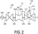
- FIG. 2 is a schematic view of the power generation facility 10 according to the present embodiment.
- the power generation facility 10 is a single-shaft type combined power generation facility (gas turbine combined cycle) in which a gas turbine 210, a steam turbine 220, and a generator 230 are configured in one shaft.
- the gas turbine 210 includes a compressor 211 that compresses an air A, a combustor 212 that combusts a fuel F with the air A compressed by the compressor 211, and a turbine 213 that is rotationally driven by a combustion gas generated in the combustor 212.
- the compressor 211 is connected to the turbine 213 via a turbine shaft 240.
- the steam turbine 220 includes a low-pressure steam turbine 221 that is rotationally driven by a low-pressure steam, and a medium-pressure/high-pressure steam turbine 222 in which a mid-pressure steam turbine 222A that is rotationally driven by a medium-pressure steam is connected to a high-pressure steam turbine 222B that is rotationally driven by a high-pressure steam.
- the low-pressure steam turbine 221 and the medium-pressure/high-pressure steam turbine 222 are connected to the generator 230 and the gas turbine 210 via the turbine shaft 240.
- the generator 230 generates power by the rotational drive of the gas turbine 210 and the steam turbine 220 via the turbine shaft 240.
- the power generation facility 10 supplies the combustion exhaust gas G 11 generated by the power generation to the waste heat recovery boiler 11 via an exhaust gas line L 11 .
- the exhaust gas line L 11 is provided with a branch exhaust gas line L 11B between a front stage and a downstream stage of the waste heat recovery boiler 11 in the exhaust gas line L 11 , the branch exhaust gas line L 11B branching from the exhaust gas line L 11 .
- the exhaust gas line L 11 is branched into a main exhaust gas line (first exhaust gas flow path) L 11A and a branch exhaust gas line (second exhaust gas flow path) L 11B between the front stage and the downstream stage of the waste heat recovery boiler 11.
- the exhaust gas line L 11 is provided with a flow rate control valve V 11A , the waste heat recovery boiler 11, and the stack 15 in this order.
- the flow rate control valve V 11A adjusts a flow rate of the combustion exhaust gas (first combustion exhaust gas) G 11A flowing through the main exhaust gas line L 11A .
- the waste heat recovery boiler 11 recovers the waste heat of the combustion exhaust gas G 11A flowing through the main exhaust gas line L 11A , and supplies the combustion exhaust gas G 11A from which the waste heat has been recovered to the stack 15.
- the stack 15 discharges a part of the combustion exhaust gas G 11A to outside as needed, and supplies the combustion exhaust gas G 11A to the integrated waste heat recovery boiler 12.
- the branch exhaust gas line L 11B is provided with a flow rate control valve V 11B .
- the flow rate control valve V 11B adjusts a flow rate of the combustion exhaust gas (second combustion exhaust gas) G 11B flowing through the branch exhaust gas line L 11B .
- the branch exhaust gas line L 11B supplies a part or all of the combustion exhaust gas G 11 flowing through the exhaust gas line L 11 to the integrated waste heat recovery boiler 12 without using the waste heat recovery boiler 11 and the stack 15.
- the integrated waste heat recovery boiler 12 is supplied with the integrated combustion exhaust gas G 21 in which the combustion exhaust gas G 11A flowing through the main exhaust gas line L 11A and the combustion exhaust gas G 11B flowing through the branch exhaust gas line L 11B are integrated.
- the integrated waste heat recovery boiler 12 recovers the waste heat of the integrated combustion exhaust gas G 21 .
- the integrated waste heat recovery boiler 12 is provided with, within thereof, a nitrogen oxide removal unit 120 that reduces and removes nitrogen oxide such as nitrogen monoxide and nitrogen dioxide contained in the integrated combustion exhaust gas G 21 . In this way, by providing the nitrogen oxide removal unit 120 within the integrated waste heat recovery boiler 12, the exhaust gas treatment device 1 can be reduced in size. Note that the nitrogen oxide removal unit 120 may not be necessarily provided in an integrated form with the integrated waste heat recovery boiler 12, and may be provided outside the integrated waste heat recovery boiler 12.
- the nitrogen oxide removal unit 120 includes a reducing agent supply unit 121 that injects a reducing agent into the integrated combustion exhaust gas G 21 to reduce nitrogen oxide, and a selective catalytic reduction (SCR) unit 122 that is provided on a downstream stage of the reducing agent supply unit 121 and filled with a DeNOx catalyst selectively reducing nitrogen oxide.
- the reducing agent in the reducing agent supply unit 121 is not specifically limited so long as it can decompose and remove nitrogen oxide such as nitrogen monoxide and nitrogen dioxide.
- the DeNOx catalyst in the selective catalytic reduction unit 122 is not specifically limited so long as it can decompose and remove nitrogen oxide such as nitrogen monoxide and nitrogen dioxide.
- the integrated waste heat recovery boiler 12 in the nitrogen oxide removal unit 120, supplies the reducing agent from the reducing agent supply unit 121 to the integrated combustion exhaust gas G 21 , and performs a decomposition treatment by the selective catalytic reduction unit 122 on nitrogen oxide supplied with the reducing agent.
- the integrated waste heat recovery boiler 12 recovers the waste heat of the integrated combustion exhaust gas G 21 of which nitrogen oxide has undergone the decomposition treatment, and supplies the integrated combustion exhaust gas G 21 from which the waste heat has been recovered to the CO 2 recovery unit 13.
- the CO 2 recovery unit 13 includes a CO 2 absorbing tower that recovers carbon dioxide (CO 2 ) in the integrated combustion exhaust gas G 21 by the CO 2 absorbing liquid, and a CO 2 regeneration tower that heats the CO 2 absorbing liquid having absorbed CO 2 to release CO 2 from the CO 2 absorbing liquid.
- a CO 2 absorbing liquid is not specifically limited so long as it can recover carbon dioxide (CO 2 ) in the integrated combustion exhaust gas G 21 , and an amine series absorbing liquid can be used, for example.
- the CO 2 recovery unit 13 discharges, to outside, the integrated combustion exhaust gas G 21 from which CO 2 has been recovered, and supplies the recovered CO 2 to the CO 2 compression portion 14.
- the CO 2 compression portion 14 compresses and discharges CO 2 supplied from the CO 2 recovery unit 13.
- the exhaust gas treatment device 1 includes a first exhaust gas measurement unit 16 that measures a gas flow rate and temperature of the integrated combustion exhaust gas G 21 introduced into the integrated waste heat recovery boiler 12, a second exhaust gas measurement unit 17 that measures a gas flow rate and nitrogen oxide concentration of the integrated combustion exhaust gas G 21 introduced into the CO 2 recovery unit 13, and a control unit 18 that controls a supply amount of a fuel F supplied to the power generation facility 10 and a supply amount of the reducing agent supplied from the reducing agent supply unit 121 to the integrated combustion exhaust gas G 21 .
- the control unit 18 adjusts opening amounts of the flow rate control valves V 11A and V 11B , and the supply amount of the fuel supplied to the power generation facility 10, based on the gas flow rate and temperature of the integrated combustion exhaust gas G 1 measured by the first exhaust gas measurement unit 16.
- the control unit 18 controls the supply amount of the fuel F supplied to the power generation facility 10, based on the gas flow rate and nitrogen oxide concentration of the integrated combustion exhaust gas G 1 measured by the second exhaust gas measurement unit 17.
- the measurement of the gas flow rate and the temperature by the first exhaust gas measurement unit 16, and the measurement of the gas flow rate and the nitrogen oxide concentration by the second exhaust gas measurement unit 17 are performed using a publicly known method of related art.
- the control unit 18 adjusts the opening amounts of the flow rate control valves V 11A and V 11B , and the supply amount of the fuel F supplied to the power generation facility 10 to control such that the temperature of the integrated combustion exhaust gas G 21 measured by the first exhaust gas measurement unit 16 is 300°C or higher and 400°C or lower.
- the exhaust gas treatment device 1 can make the temperature of the integrated combustion exhaust gas G 21 supplied to the nitrogen oxide removal unit 120 in the integrated waste heat recovery boiler 12 a temperature suitable for decomposing and removing nitrogen oxide, so that nitrogen oxide in the integrated combustion exhaust gas G 21 can be further more efficiently decomposed and removed.
- the control unit 18 controls at least one of the opening amount of the flow rate control valve V 11A to be decreased and the opening amount of the flow rate control valve V 11B to be increased, so that a ratio, in the integrated combustion exhaust gas G 21 , of the combustion exhaust gas G 11B having flowed through the branch exhaust gas line L 11B is increased with respect to the combustion exhaust gas G 11A having flowed through the main exhaust gas line L 11A .
- the control unit 18 may maintain the opening amounts of the flow rate control valves V 11A and V 11B to increase the feed amount of the fuel F supplied to the power generation facility 10 so as to increase the temperature of the integrated combustion exhaust gas G 21 .
- the control unit 18 controls at least one of the opening amount of the flow rate control valve V 11A to be increased and the opening amount of the flow rate control valve V 11B to be decreased, so that the ratio, in the integrated combustion exhaust gas G 21 , of the combustion exhaust gas G 11B flowing through the branch exhaust gas line L 11B is decreased with respect to the combustion exhaust gas G 11A flowing through the main exhaust gas line L 11A .
- the control unit 18 may maintain the opening amounts of the flow rate control valves V 11A and V 11B to decrease the feed amount of the fuel F supplied to the power generation facility 10 so as to decrease the temperature of the integrated combustion exhaust gas G 21 .
- the control unit 18 adjusts the supply amount of the reducing agent supplied from the reducing agent supply unit 121, and controls the nitrogen oxide concentration in the integrated combustion exhaust gas G 21 measured by the second exhaust gas measurement unit 17 to be a predetermined value or less. In case that the nitrogen oxide concentration in the integrated combustion exhaust gas G 21 measured by the second exhaust gas measurement unit 17 exceeds the predetermined value, the control unit 18 increases the supply amount of the reducing agent from the reducing agent supply unit 121. In case that the nitrogen oxide concentration in the integrated combustion exhaust gas G 21 measured by the second exhaust gas measurement unit 17 is less than the predetermined value, the control unit 18 maintains or decreases the supply amount of the reducing agent from the reducing agent supply unit 121.
- the exhaust gas treatment device 1 can control the nitrogen oxide concentration in the integrated combustion exhaust gas G 21 introduced into the CO 2 recovery unit 13 to be the predetermined value or less, so that it is possible to efficiently reduce the nitrogen oxide in the integrated combustion exhaust gas G 21 after CO 2 discharged from the CO 2 recovery unit 13 is recovered.
- the combustion exhaust gas G 11 discharged from the power generation facility 10 via the exhaust gas line L 11 is branched into the combustion exhaust gas G 11A flowing through the main exhaust gas line L 11A and the combustion exhaust gas G 11B flowing through the branch exhaust gas line L 11B .
- the combustion exhaust gas G 11A flowing through the main exhaust gas line L 11A with the waste heat of the gas G 11A being recovered by the waste heat recovery boiler 11 to decrease the temperature, after a part of the gas G 11A is discharged from the stack 15, is integrated in the exhaust gas line L 11 with the combustion exhaust gas G 11B flowing through the branch exhaust gas line L 11B .
- the combustion exhaust gas G 11B flowing through the branch exhaust gas line L 11B in a state of a high temperature without via the waste heat recovery boiler 11, is integrated in the exhaust gas line L 11 with the combustion exhaust gas G 11A flowing through the main exhaust gas line.
- the integrated combustion exhaust gas G 21 in which the combustion exhaust gas G 11A and the combustion exhaust gas G 11B are integrated is supplied via the exhaust gas line L 11 to the integrated waste heat recovery boiler 12.
- the control unit 18 controls valve opening amounts of the flow rate control valves V 11A and V 11B and the supply amount of the fuel F supplied to the power generation facility 10 as needed, such that the temperature of the integrated combustion exhaust gas G 21 is a predetermined temperature (for example, 300°C or higher and 400°C or lower).
- the integrated combustion exhaust gas G 21 supplied to the integrated waste heat recovery boiler 12 is supplied with the reducing agent by the reducing agent supply unit 121 in the nitrogen oxide removal unit 120, and, after nitrogen oxide is decomposed and removed by selective catalytic reduction unit 122, is supplied to the CO 2 recovery unit 13.
- control unit 18 controls an amount of the reducing agent supplied from the reducing agent supply unit 121 to the integrated combustion exhaust gas G 21 as needed, such that nitrogen oxide in the integrated combustion exhaust gas G 21 supplied to the CO 2 recovery unit 13 is a predetermined value or less.
- CO 2 in the integrated combustion exhaust gas G 21 recovered by the CO 2 absorbing liquid is heated to be released from the CO 2 absorbing liquid, and thereafter, supplied to the CO 2 compression portion 14, and compressed and discharged.
- the combustion exhaust gas G 11 discharged from the power generation facility 10 is branched into the main exhaust gas line L 11A and the branch exhaust gas line L 11B , and thereafter, the waste heat of the combustion exhaust gas G 11A is recovered by the waste heat recovery boiler 11 provided to the main exhaust gas line L 11A , while the combustion exhaust gas G 11A after the waste heat is recovered is integrated with the combustion exhaust gas G 11B flowing through the branch exhaust gas line L 11B in a state of high temperature that the temperature is higher than the combustion exhaust gas G 11A , to be the integrated combustion exhaust gas G 21 .
- waste heat recovery boiler 11 is provided to the main exhaust gas line L 11A , but the waste heat recovery boiler 11 may be configured to be provided to the branch exhaust gas line L 11B , or the waste heat recovery boiler 11 may be configured to be provided to both the main exhaust gas line L 11A and the branch exhaust gas line L 11B .
- the integrated combustion exhaust gas G 21 can be adjusted to a desired temperature by differentiating a recovery amount of the waste heat from the combustion exhaust gas G 11A in the waste heat recovery boiler 11 on the main exhaust gas line L 11A from a recovery amount of the waste heat from the combustion exhaust gas G 11B in the waste heat recovery boiler 11 on the branch exhaust gas line L 11B .
- the power generation facility 10 may be an existing power generation facility, or a newly built power generation facility. In a case where the power generation facility 10 is an existing power generation facility, the configuration of the exhaust gas treatment device 1 according to the above-described embodiment can be obtained by simply providing the branch exhaust gas line L 11B to an existing exhaust gas line.
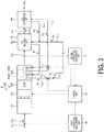
- FIG. 3 is a schematic view illustrating another example of the exhaust gas treatment device 1 according to the above-described embodiment.
- the integrated waste heat recovery boiler 12 includes a steam generation unit 123 provided on a downstream stage of the nitrogen oxide removal unit 120.
- the steam generation unit 123 includes a turbine-driving steam generation unit 123A provided on a downstream stage of the nitrogen oxide removal unit 120 in the flow direction of the integrated combustion exhaust gas G 21 , and a CO 2 compression portion-driving steam generation unit 123B provided on a downstream stage of the turbine-driving steam generation unit 123A.
- the turbine-driving steam generation unit 123A recovers the waste heat of the integrated combustion exhaust gas G 21 from which nitrogen oxide has been removed to generate a turbine-driving steam S 1 that is a low-pressure steam for driving the low-pressure steam turbine 19.
- the turbine-driving steam generation unit 123A supplies the generated turbine-driving steam S 1 to the low-pressure steam turbine 19 via a steam supply line L 12 .
- the low-pressure steam turbine 19 may be a turbine provided outside the exhaust gas treatment device 2, or the low-pressure steam turbine 221 in the power generation facility 10 illustrated in FIG. 2 .
- the low-pressure steam turbine 19 is rotationally driven by the turbine-driving steam S 1 to generate power by a generator (not illustrated in the drawing).
- the low-pressure steam turbine 19 supplies the turbine-driving steam S 1 after driving the turbine as a CO 2 absorbing liquid-regenerating steam S 2 to the CO 2 recovery unit 13 via a steam discharge line L 13 .
- the CO 2 compression portion-driving steam generation unit 123B recovers the waste heat of the integrated combustion exhaust gas G 21 from which nitrogen oxide has been removed to generate a CO 2 compression portion-driving steam S 3 that is a low-pressure steam for driving the CO 2 compression portion 14.
- the CO 2 compression portion-driving steam generation unit 123B supplies the generated CO 2 compression portion-driving steam S 3 to the CO 2 compression portion 14 via a steam supply line L 14 .
- the CO 2 compression portion 14 drives the CO 2 compression portion by using the CO 2 compression portion-driving steam S 3 to compress CO 2 .
- the CO 2 compression portion 14 supplies the CO 2 compression portion-driving steam S 3 after driving the CO 2 compression portion as a CO 2 absorbing liquid-regenerating steam S 4 to the CO 2 recovery unit 13 via a steam discharge line L 15 .
- the CO 2 recovery unit 13 supplies the CO 2 absorbing liquid-regenerating steams S 2 and S 4 to a reboiler in the CO 2 regeneration tower to release CO 2 from the CO 2 absorbing liquid having recovered CO 2 . This allows the exhaust gas treatment device 2 to reduce the steam used for the reboiler in the CO 2 absorbing tower.
- the CO 2 recovery unit 13 supplies a condensed water W in which condensed is the CO 2 absorbing liquid-regenerating steams S 2 and S 4 having been used for the reboiler in the CO 2 absorbing tower to the turbine-driving steam generation unit 123A and the CO 2 compression portion-driving steam generation unit 123B in the integrated waste heat recovery boiler 12.
- the control unit 18 controls a supply amount of the fuel F supplied to the combustor 212 in the power generation facility 10, a supply amount of the turbine-driving steam S 1 supplied to the low-pressure steam turbine 19, and a supply amount of the CO 2 compression portion-driving steam S 3 supplied to the CO 2 compression portion 14, based on the temperature and gas flow rate of the integrated combustion exhaust gas G 21 , measured by the first exhaust gas measurement unit 16 and introduced into the nitrogen oxide removal unit 120. In a case where the temperature and gas flow rate of the integrated combustion exhaust gas G 21 introduced into the nitrogen oxide removal unit 120 is less than a predetermined range, the control unit 18 increases the fuel F supplied to the combustor 212 in the power generation facility 10.
- the control unit 18 decreases the fuel F supplied to the combustor 212 in the power generation facility 10. In a case where the temperature and gas flow rate of the integrated combustion exhaust gas G 21 introduced into the nitrogen oxide removal unit 120 is less than the predetermined range, the control unit 18 decreases an opening amount of at least one of a flow rate control valve V 12 provided to the steam supply line L 12 and a flow rate control valve V 14 provided to the steam supply line L 14 to decrease the supply amount of at least one of the turbine-driving steam S 1 supplied to the low-pressure steam turbine 19 and the CO 2 compression portion-driving steam S 3 supplied to the CO 2 compression portion 14.
- the control unit 18 increases the opening amount of at least one of the flow rate control valve V 12 provided to the steam supply line L 12 and the flow rate control valve V 14 provided to the steam supply line L 14 to increase the supply amount of at least one of the turbine-driving steam S 1 supplied to the low-pressure steam turbine 19 and the CO 2 compression portion-driving steam S 3 supplied to the CO 2 compression portion 14.
- the temperature of the integrated combustion exhaust gas G 21 introduced into the nitrogen oxide removal unit 120 can be controlled to be in a range suitable for decomposing and removing nitrogen oxide, so that nitrogen oxide in the integrated combustion exhaust gas G 21 can be efficiently reduced.
- the turbine-driving steam generation unit 123A and the CO 2 compression portion-driving steam generation unit 123B in the integrated waste heat recovery boiler 12 by virtue of the turbine-driving steam S 1 required for rotationally driving the low-pressure steam turbine 19, the CO 2 compression portion-driving steam S 3 required for compressing CO 2 , and the CO 2 absorbing liquid-regenerating steams S 2 and S 4 required for regenerating the CO 2 absorbing liquid can be acquired, so that an amount of the steam used in the whole exhaust gas treatment device 2 can be reduced.
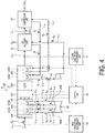
- FIG. 4 is a schematic view illustrating another example of the exhaust gas treatment device 2 according to the above-described embodiment.
- the integrated waste heat recovery boiler 12 includes, besides the steam generation unit 123 illustrated in FIG. 3 , a heating unit 124 provided on a front stage of the nitrogen oxide removal unit 120 where is an introducing part of the integrated combustion exhaust gas G 21 , and a steam generation unit 125 provided between the heating unit 124 and the nitrogen oxide removal unit 120.
- the steam generation unit 125 is provided on a downstream stage of the heating unit 124, and includes a turbine-driving steam generation unit 125A that generates a high-pressure steam for rotationally driving a high-pressure steam turbine 20A of a medium-pressure/high-pressure steam turbine 20, and a turbine-driving steam generation unit 125B that is provided on a downstream stage of the turbine-driving steam generation unit 125A and generates a medium-pressure steam for rotationally driving a mid-pressure steam turbine 20B of the medium-pressure/high-pressure steam turbine 20.
- the heating unit 124 heats the integrated combustion exhaust gas G 21 introduced into the integrated waste heat recovery boiler 12 (for example, 500°C or higher and 600°C or lower), and supplies the heated integrated combustion exhaust gas G 21 to the turbine-driving steam generation unit 125A in the steam generation unit 125.
- the integrated combustion exhaust gas G 21 can be heated by use of a publicly known general heating device. In a case where the temperature of the integrated combustion exhaust gas G 21 introduced into the integrated waste heat recovery boiler 12 is high, the heating unit 124 may not be necessarily provided.
- the turbine-driving steam generation unit 125A recovers the waste heat of the integrated combustion exhaust gas G 21 heated by the heating unit 124 to generate a turbine-driving steam S 5 that is a high-pressure steam for driving the high-pressure steam turbine 20A of the medium-pressure/high-pressure steam turbine 20.
- the turbine-driving steam generation unit 125A supplies the generated turbine-driving steam S 5 to the high-pressure steam turbine 20A via a steam supply line L 16 .
- the medium-pressure/high-pressure steam turbine 20 may be that provided outside the exhaust gas treatment device 3, or the medium-pressure/high-pressure steam turbine 222 in the power generation facility 10 illustrated in FIG. 2 .
- the high-pressure steam turbine 20A is rotationally driven by the turbine-driving steam S 5 to generate power by a generator (not illustrated in the drawing). This allows the exhaust gas treatment device 3 to generate power by using the waste heat of the integrated combustion exhaust gas G 21 recovered by the integrated waste heat recovery boiler 12, and therefore, the steam required for driving the medium-pressure/high-pressure steam turbine 20 can be reduced.
- the high-pressure steam turbine 20A supplies a turbine-driving steam S 6 after driving the turbine to the turbine-driving steam generation unit 125A via a steam discharge line L 17 .
- the turbine-driving steam generation unit 125B recovers the waste heat of the integrated combustion exhaust gas G 21 heated by the heating unit 124 to generate a turbine-driving steam S 7 that is a medium-pressure steam for driving the mid-pressure steam turbine 20B of the medium-pressure/high-pressure steam turbine 20.
- the turbine-driving steam generation unit 125B supplies the generated turbine-driving steam S 7 to the mid-pressure steam turbine 20B via a steam supply line Lis.
- the mid-pressure steam turbine 20B is rotationally driven by the turbine-driving steam S 7 to generate power by a generator (not illustrated in the drawing).
- the mid-pressure steam turbine 20B supplies a turbine-driving steam S 8 after driving the turbine to the turbine-driving steam generation unit 125B via a steam discharge line L 19 .
- the control unit 18 controls supply amounts of the turbine-driving steams S 5 and S 7 supplied to the medium-pressure/high-pressure steam turbine 20, based on the temperature and gas flow rate of the integrated combustion exhaust gas G 21 , measured by the first exhaust gas measurement unit 16 and introduced into the nitrogen oxide removal unit 120. In a case where the temperature and gas flow rate of the integrated combustion exhaust gas G 21 introduced into the nitrogen oxide removal unit 120 is less than a predetermined range, the control unit 18 decreases an opening amount of at least one of a flow rate control valve V 16 provided to the steam supply line L 16 and a flow rate control valve V 18 provided to the steam supply line L 18 to decrease at least one of the turbine-driving steams S 5 and S 7 supplied to the medium-pressure/high-pressure steam turbine 20.
- the control unit 18 increases the opening amount of at least one of the flow rate control valve V 16 provided to the steam supply line L 16 and the flow rate control valve V 18 provided to the steam supply line L 18 to increase at least one of the supply amounts of the turbine-driving steams S 5 and S 7 supplied to the medium-pressure/high-pressure steam turbine 20.
- the temperature of the integrated combustion exhaust gas G 21 introduced into the nitrogen oxide removal unit 120 can be controlled to be in a range suitable for decomposing and removing nitrogen oxide, so that nitrogen oxide in the integrated combustion exhaust gas G 21 can be efficiently reduced.
- the turbine-driving steam generation units 125A and 125B in the integrated waste heat recovery boiler 12 by virtue of the turbine-driving steam generation units 125A and 125B in the integrated waste heat recovery boiler 12, the turbine-driving steams S 5 and S 7 required for rotationally driving the medium-pressure/high-pressure steam turbine 20 can be acquired, so that an amount of the steam used in the whole exhaust gas treatment device 3 can be reduced.
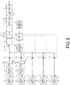
- FIG. 5 is a schematic view illustrating an example of an exhaust gas treatment device 4 according to the second embodiment of the present invention.
- the exhaust gas treatment device 4 according to the present embodiment recovers waste heat of combustion exhaust gases G 11-1 and G 11-2 respectively discharged from two power generation facilities 10-1 and 10-2 by the integrated waste heat recovery boiler 12, and thereafter, recovers CO 2 contained in the combustion exhaust gases G 11-1 and G 11-2 by the CO 2 recovery unit 13.
- the exhaust gas treatment device 4 includes the power generation facility (first power generation facility) 10-1 discharging the combustion exhaust gas (first combustion exhaust gas) G 11-1 , the power generation facility (second power generation facility) 10-2 discharging the combustion exhaust gas (second combustion exhaust gas) G 11-2 , a waste heat recovery boiler 11-1 provided on a downstream stage of the power generation facility 10-1 in a flow direction of the combustion exhaust gas G 11-1 , the integrated waste heat recovery boiler 12 provided on a downstream stage of the waste heat recovery boiler 11-1, the CO 2 recovery unit 13 provided on a downstream stage of the integrated waste heat recovery boiler 12, and the CO 2 compression portion 14 provided on a downstream stage of the CO 2 recovery unit 13.
- a stack 15-1 discharging a part of the combustion exhaust gas G 11-1 is provided between the waste heat recovery boiler 11-1 and the integrated waste heat recovery boiler 12.
- the power generation facility 10-1 discharges the combustion exhaust gas G 11-1 generated by the power generation to an exhaust gas line (first exhaust gas flow path) L 11-1 .
- the exhaust gas line L 11-1 is provided with the waste heat recovery boiler 11-1, the stack 15-1, and a flow rate control valve V 11-1 in this order.
- the flow rate control valve V 11-1 adjusts a flow rate of the combustion exhaust gas G 11-1 flowing through the exhaust gas line L 11-1 .
- the waste heat recovery boiler 11-1 recovers the waste heat of the combustion exhaust gas G 11-1 that is discharged from the power generation facility 10-1 and flows through the exhaust gas line L 11-1 , and supplies the combustion exhaust gas G 11-1 from which the waste heat has been recovered to the stack 15-1.
- the stack 15-1 discharges a part of the combustion exhaust gas G 11-1 to outside as needed, and supplies the combustion exhaust gas G 11-1 to the integrated waste heat recovery boiler 12.
- the power generation facility 10-2 discharges the combustion exhaust gas G 11-2 generated by the power generation to an exhaust gas line (second exhaust gas flow path) L 11-2 .
- the exhaust gas line L 11-2 is provided with a flow rate control valve V 11-2 .
- the flow rate control valve V 11-2 adjusts a flow rate of the combustion exhaust gas G 11-2 flowing through the exhaust gas line L 11-2 .
- the integrated waste heat recovery boiler 12 is supplied with the integrated combustion exhaust gas G 21 in which the combustion exhaust gas G 11-1 flowing through the exhaust gas line L 11-1 and the combustion exhaust gas G 11-2 flowing through the exhaust gas line L 11-2 are integrated.
- the integrated waste heat recovery boiler 12 is provided with the nitrogen oxide removal unit 120 that reduces and removes nitrogen oxide such as nitrogen monoxide and nitrogen dioxide contained in the integrated combustion exhaust gas G 21 .
- the exhaust gas treatment device 4 includes the control unit 18 that controls opening amounts of the flow rate control valve V 11-1 and flow rate control valve V 11-2 , and the supply amount of the fuel supplied to the power generation facility 10, based on the gas flow rate and temperature of the integrated combustion exhaust gas G 21 measured by the first exhaust gas measurement unit 16.
- the control unit 18 adjusts the opening amounts of the flow rate control valve V 11-1 and flow rate control valve V 11-2 , and the supply amounts of the fuels F supplied to the power generation facilities 10-1 and 10-2 to control such that the temperature of the integrated combustion exhaust gas G 21 measured by the first exhaust gas measurement unit 16 is 300°C or higher and 400°C or lower.
- the exhaust gas treatment device 4 can make the temperature of the integrated combustion exhaust gas G 21 supplied to the nitrogen oxide removal unit 120 in the integrated waste heat recovery boiler 12 a temperature suitable for decomposing and removing nitrogen oxide, so that nitrogen oxide in the integrated combustion exhaust gas G 21 can be further more efficiently decomposed and removed.
- the control unit 18 controls at least one of the opening amount of the flow rate control valve V 11-1 to be decreased and the opening amount of the flow rate control valve V 11-2 to be increased, so that a ratio, in the integrated combustion exhaust gas G 21 , of the combustion exhaust gas G 11-2 flowing through the exhaust gas line L 11-2 is increased with respect to the combustion exhaust gas G 11-1 flowing through the exhaust gas line L 11-1 .
- the control unit 18 may maintain the opening amounts of the flow rate control valve V 11-1 and flow rate control valve V 11-2 to increase the supply amount of the fuel supplied to the power generation facility 10 so as to increase the temperature of the integrated combustion exhaust gas G 21 .
- the control unit 18 controls at least one of the opening amount of the flow rate control valve V 11-1 to be increased and the opening amount of the flow rate control valve V 11-2 to be decreased, so that the ratio, in the integrated combustion exhaust gas G 21 , of the combustion exhaust gas G 11-2 flowing through the exhaust gas line L 11-2 is decreased with respect to the combustion exhaust gas G 11-1 flowing through the exhaust gas line L 11-1 .
- the control unit 18 may maintain the opening amounts of the flow rate control valve V 11-1 and flow rate control valve V 11-2 to decrease the supply amount of the fuel supplied to the power generation facility 10 so as to decrease the temperature of the integrated combustion exhaust gas G 21 .
- descriptions are omitted since the other components are the same as those of the exhaust gas treatment device 1 illustrated in FIG. 1 .
- the combustion exhaust gas G 11-2 discharged from the power generation facility 10-2 is supplied via the exhaust gas line L 11-2 to the integrated exhaust gas line L 21 .
- the combustion exhaust gas G 11-1 and the combustion exhaust gas G 11-2 are integrated to obtain the integrated combustion exhaust gas G 21 , where the waste heat of the combustion exhaust gas G 11-1 is recovered by the waste heat recovery boiler 11-1 to decrease the temperature thereof and the combustion exhaust gas G 11-2 has a temperature higher relative to the combustion exhaust gas G 11-1 , and the resultant integrated combustion exhaust gas G 21 is supplied to the integrated waste heat recovery boiler 12.
- the control unit 18 controls the opening amounts of the flow rate control valves V 11-1 and V 11-2 and the supply amount of the fuel F supplied to the power generation facility 10 as needed, such that the temperature of the integrated combustion exhaust gas G 21 is a predetermined temperature (for example, 300°C or higher and 400°C or lower).
- the integrated combustion exhaust gas G 21 supplied to the integrated waste heat recovery boiler 12 is supplied with the reducing agent by the reducing agent supply unit 121 in the nitrogen oxide removal unit 120, and, after nitrogen oxide is decomposed and removed by selective catalytic reduction unit 122, is supplied to the CO 2 recovery unit 13.
- the control unit 18 controls an amount of the reducing agent supplied from the reducing agent supply unit 121 to the integrated combustion exhaust gas G 21 as needed, such that nitrogen oxide in the integrated combustion exhaust gas G 21 supplied to the CO 2 recovery unit 13 is a predetermined value or less.
- the integrated combustion exhaust gas G 21 supplied to the CO 2 recovery unit 13, after CO 2 is recovered by the CO 2 absorbing liquid, is discharged out of the exhaust gas treatment device 4. CO 2 in the integrated combustion exhaust gas G 21 recovered by the CO 2 absorbing liquid is heated to be released from the CO 2 absorbing liquid, and thereafter, supplied to the CO 2 compression portion 14, and compressed and discharged.
- the waste heat of the combustion exhaust gas G 11-1 discharged from the power generation facility 10-1 is recovered by the waste heat recovery boiler 11-1 provided to the exhaust gas line L 11-1 , while the combustion exhaust gas G 11-1 after the waste heat is recovered is integrated with the combustion exhaust gas G 11-2 discharged from the power generation facility 10-2 and flowing through the exhaust gas line L 11-2 in a state of high temperature that the temperature is higher than the combustion exhaust gas G 11-1 , and then, the integrated combustion exhaust gas G 21 is resulted.
- waste heat recovery boiler 11-1 is provided to the exhaust gas line L 11-1 , but the waste heat recovery boiler 11-1 may be configured to be provided to the exhaust gas line L 11-2 , or the waste heat recovery boiler 11-1 may be configured to be provided to both the exhaust gas line L 11-1 and the exhaust gas line L 11-2 .
- the integrated combustion exhaust gas G 21 can be adjusted to a desired temperature by differentiating a recovery amount of the waste heat from the combustion exhaust gas G 11-1 in the waste heat recovery boiler 11-1 on the exhaust gas line L 11-1 from a recovery amount of the waste heat from the combustion exhaust gas G 11-2 in the waste heat recovery boiler 11 on the exhaust gas line L 11-2 .
- Each of two power generation facilities 10-1 and 10-2 may be an existing power generation facility, or a newly built power generation facility.
- the integrated combustion exhaust gas G 21 can be adjusted to a desired temperature only by newly providing the power generation facility 10-2 and the exhaust gas line L 11-2 .
- the configuration of the integrated waste heat recovery boiler 12 may be the same as the configuration illustrated in FIG. 3 or FIG. 4 .
- FIG. 6 is a schematic view illustrating another example of the exhaust gas treatment device 4 according to the second embodiment of the present invention.
- an exhaust gas treatment device 5 according to the present embodiment recovers waste heat of combustion exhaust gases G 11-1 , G 11-2 , G 11-3 , G 11-4 , and G 11-5 respectively discharged from five power generation facilities 10-1, 10-2, 10-3, 10-4, and 10-5 by the integrated waste heat recovery boiler 12, and thereafter, recovers CO 2 contained in the combustion exhaust gases G 11-1 , G 11-2 , G 11-3 , G 11-4 , and G 11-5 by the CO 2 recovery unit 13.
- the exhaust gas treatment device 5 includes the power generation facility (first power generation facility) 10-1 discharging the combustion exhaust gas (first combustion exhaust gas) G 11-1 , the power generation facility (first power generation facility) 10-2 discharging the combustion exhaust gas (first combustion exhaust gas) G 11-2 , the power generation facility (second power generation facility) 10-3 discharging the combustion exhaust gas (second combustion exhaust gas) G 11-3 , the power generation facility (second power generation facility) 10-4 discharging the combustion exhaust gas (second combustion exhaust gas) G 11-4 , the power generation facility (second power generation facility) 10-5 discharging the combustion exhaust gas (second combustion exhaust gas) G 11-5 , the waste heat recovery boiler 11-1 provided on a downstream stage of the power generation facility 10-1 in a flow direction of the combustion exhaust gas G 11-1 , a waste heat recovery boiler 11-2 provided on a downstream stage of the power generation facility 10-2 in a flow direction of the combustion exhaust gas G 11-2 , the integrated waste heat recovery boiler 12 provided on a downstream stage of the waste heat recovery boiler 11-1, the CO 2 recovery
- the stack 15-1 discharging a part of the combustion exhaust gas G 11-1 is provided between the waste heat recovery boiler 11-1 and the integrated waste heat recovery boiler 12, and a stack 15-2 discharging a part of the combustion exhaust gas G 11-2 is provided between the waste heat recovery boiler 11-2 and the integrated waste heat recovery boiler 12.
- the power generation facilities 10-1 and 10-2 discharge the combustion exhaust gases G 11-1 and G 11-2 generated by the power generation to the exhaust gas lines (first exhaust gas flow path) L 11-1 and L 11-2 .
- the exhaust gas lines L 11-1 and L 11-2 are provided with respectively the waste heat recovery boilers 11-1 and 11-2, the stacks 15-1 and 15-2, and the flow rate control valves V 11-1 and V 11-2 in this order.
- the flow rate control valves V 11-1 and V 11-2 adjust flow rates of the combustion exhaust gases G 11-1 and G 11-2 flowing through the exhaust gases lines L 11-1 and L 11-2 , respectively.
- the waste heat recovery boilers 11-1 and 11-2 recover the waste heat of the combustion exhaust gases G 11-1 and G 11-2 that are discharged from the power generation facilities 10-1 and 10-2 and flow through the exhaust gas lines L 11-1 and L 11-2 , and supply the combustion exhaust gases G 11-1 and G 11-2 from which the waste heat has been recovered to the stacks 15-1 and 15-2, respectively.
- the stacks 15-1 and 15-2 supply the combustion exhaust gases G 11-1 and G 11-2 to the integrated waste heat recovery boiler 12, and discharge a part of the combustion exhaust gases G 11-1 and G 11-2 to outside as needed.
- the power generation facilities 10-3, 10-4, and 10-5 discharge the combustion exhaust gases G 11-3 , G 11-4 and G 11-5 generated by the power generation to the exhaust gas lines (second exhaust gas flow path) L 11-3 , L 11-4 and L 11-5 , respectively.
- the exhaust gas lines L 11-3 , L 11-4 and L 11-5 are provided with flow rate control valves V 11-3 , V 11-4 , and V 11-5 , respectively.
- the flow rate control valves V 11-3 , V 11-4 , and V 11-5 adjust flow rates of the combustion exhaust gases G 11-3 , G 11-4 , and G 11-5 flowing through the exhaust gases lines L 11-3 , L 11-4 and L 11-5 , respectively.
- the integrated waste heat recovery boiler 12 is supplied with the integrated combustion exhaust gas G 21 in which the combustion exhaust gases G 11-1 , G 11-2 , G 11-3 , G 11-4 , and G 11-5 flowing through the exhaust gas lines L 11-1 , L 11-2 , L 11-3 , L 11-4 , and L 11-5 are integrated.
- the integrated waste heat recovery boiler 12 is provided with, within thereof, the nitrogen oxide removal unit 120 that reduces and removes nitrogen oxide such as nitrogen monoxide and nitrogen dioxide contained in the integrated combustion exhaust gas G 21 .
- the exhaust gas treatment device 5 includes the control unit 18 that controls opening amounts of the flow rate control valves V 11-1 , V 11-2 , V 11-3 , V 11-4 , and V 11-5 and supply amounts of the fuels F supplied to the power generation facilities 10-1, 10-2, 10-3, 10-4, and 10-5, based on the gas flow rate and temperature of the integrated combustion exhaust gas G 21 measured by the first exhaust gas measurement unit 16.
- the control unit 18 adjusts respectively the opening amounts of the flow rate control valves V 11-1 , V 11-2 , V 11-3 , V 11-4 , and V 11-5 , and the supply amounts of the fuels F supplied to the power generation facilities 10-1, 10-2, 10-3, 10-4, and 10-5 to control such that the temperature of the integrated combustion exhaust gas G 21 measured by the first exhaust gas measurement unit 16 is 300°C or higher and 400°C or lower.
- the exhaust gas treatment device 5 can make the temperature of the integrated combustion exhaust gas G 21 supplied to the nitrogen oxide removal unit 120 in the integrated waste heat recovery boiler 12 a temperature suitable for decomposing and removing nitrogen oxide, so that nitrogen oxide in the integrated combustion exhaust gas G 21 can be further more efficiently decomposed and removed.
- the control unit 18 controls at least one of the opening amounts of the flow rate control valves V 11-1 and V 11-2 to be decreased and the opening amounts of the flow rate control valves V 11-3 , V 11-4 , and V 11-5 to be increased, so that a ratio, in the integrated combustion exhaust gas G 21 , of the combustion exhaust gases G 11-3 , G 11-4 , and G 11-5 flowing through the exhaust gas lines L 11-3 , L 11-4 , and L 11-5 is increased with respect to the combustion exhaust gases G 11-1 and G 11-2 flowing through the exhaust gas lines L 11-1 and L 11-2 .
- This can increase the ratio of the combustion exhaust gases G 11-3 , G 11-4 , and G 11-5 relative to the combustion exhaust gases G 11-1 and G 11-2 , where the temperatures of the combustion exhaust gases G 11-1 and G 11-2 are decreased because the heats thereof have been recovered by the waste heat recovery boilers 11-1 and 11-2, and where the
- the control unit 18 may maintain the opening amounts of the flow rate control valves V 11-1 , V 11-2 , V 11-3 , V 11-4 , and V 11-5 to increase the supply amounts of the fuels F supplied to the power generation facilities 10-1, 10-2, 10-3, 10-4, and 10-5 so as to increase the temperature of the integrated combustion exhaust gas G 21 .
- the control unit 18 controls at least one of the opening amounts of the flow rate control valves V 11-1 and V 11-2 to be increased and the opening amounts of the flow rate control valves V 11-3 , V 11-4 , and V 11-5 to be decreased, so that the ratio, in the integrated combustion exhaust gas G 21 , of the combustion exhaust gases G 11-3 , G 11-4 , and G 11-5 flowing through the exhaust gas lines L 11-3 , L 11-4 , and L 11-5 is decreased with respect to the combustion exhaust gas G 11-1 and G 11-2 flowing through the exhaust gas lines L 11-1 and L 11-2 .
- the control unit 18 may maintain the opening amounts of the flow rate control valves V 11-1 , V 11-2 , V 11-3 , V 11-4 , and V 11-5 to decrease the supply amount of the fuel supplied to the power generation facility 10 so as to decrease the temperature of the integrated combustion exhaust gas G 21 .
- the other components descriptions are omitted since the other components are the same as those of the exhaust gas treatment device 1 illustrated in FIG. 1 .
- the combustion exhaust gases G 11-3 , G 11-4 , and G 11-5 discharged from the power generation facilities 10-3, 10-4, and 10-5 are supplied via the exhaust gas lines L 11-3 , L 11-4 , and L 11-5 to the integrated exhaust gas line L 21 .
- the combustion exhaust gases G 11-1 and G 11-2 and the combustion exhaust gases G 11-3 , G 11-4 , and G 11-5 are integrated to obtain the integrated combustion exhaust gas G 21 , where the waste heat of the combustion exhaust gases G 11-1 and G 11-2 is recovered by the waste heat recovery boilers 11-1 and 11-2 to decrease the temperatures thereof and the combustion exhaust gases G 11-3 , G 11-4 , and G 11-5 have temperatures higher relative to the combustion exhaust gases G 11-1 and G 11-2 , and the resultant integrated combustion exhaust gas G 21 is supplied to the integrated waste heat recovery boiler 12.
- control unit 18 controls the opening amounts of the flow rate control valves V 11-1 and V 11-2 and the supply amount of the fuel supplied to the power generation facility 10 as needed, such that the temperature of the integrated combustion exhaust gas G 21 is a predetermined temperature (for example, 300°C or higher and 400°C or lower).
- the integrated combustion exhaust gas G 21 supplied to the integrated waste heat recovery boiler 12 is supplied with the reducing agent by the reducing agent supply unit 121 in the nitrogen oxide removal unit 120, and, after nitrogen oxide is decomposed and removed by selective catalytic reduction unit 122, is supplied to the CO 2 recovery unit 13.
- control unit 18 controls an amount of the reducing agent supplied from the reducing agent supply unit 121 to the integrated combustion exhaust gas G 21 as needed, such that nitrogen oxide in the integrated combustion exhaust gas G 21 supplied to the CO 2 recovery unit 13 is a predetermined value or less.
- CO 2 in the integrated combustion exhaust gas G 21 recovered by the CO 2 absorbing liquid is heated to be released from the CO 2 absorbing liquid, and thereafter, supplied to the CO 2 compression portion 14, and compressed and discharged.
- the waste heat of the combustion exhaust gases G 11-1 and G 11-2 discharged from the power generation facilities 10-1 and 10-2 is recovered by the waste heat recovery boilers 11-1 and 11-2 provided to the exhaust gas lines L 11-1 and L 11-2 , while the combustion exhaust gases G 11-1 and G 11-2 after the waste heat is recovered are integrated with the combustion exhaust gas G 11-2 discharged from the power generation facilities 10-3, 10-4, and 10-5 and flowing through the exhaust gas lines L 11-3 , L 11-4 , and L 11-5 in a state of high temperature that the temperature is higher than the combustion exhaust gases G 11-1 and G 11-2 , and then, the integrated combustion exhaust gas G 21 is resulted.
- waste heat recovery boilers 11-1 and 11-2 are provided to the exhaust gas lines L 11-1 and L 11-2 , but the waste heat recovery boiler 11 may be configured to be provided to at least one exhaust gas line L 11 , or the waste heat recovery boiler 11 may be configured to be provided to all of the exhaust gas lines L 11-1 , L 11-2 , L 11-3 , L 11-4 , and L 11-5 .
- the integrated combustion exhaust gas G 21 can be adjusted to a desired temperature by differentiating recovery amounts of the waste heat from the combustion exhaust gases G 11-1 , G 11-2 , G 11-3 , G 11-4 , and G 11-5 in the waste heat recovery boiler 11 on the exhaust gas lines L 11-1 , L11-2, L 11-3 , L 11-4 , and L 11-5 .
- Each of the power generation facilities 10-1, 10-2, 10-3, 10-4, and 10-5 may be an existing power generation facility, or a newly built power generation facility.
- the configuration of the integrated waste heat recovery boiler 12 may be the same as the configuration illustrated in FIG. 3 or FIG. 4 .
- the present inventors investigated in detail effects to reduce the accumulation amount of the nitrogen oxide (NO 2 )-derived component in the CO 2 absorbing liquid in the exhaust gas treatment device according to the above-described embodiment.
- content investigated by the present inventor will be described.
- FIG. 7 is an explanatory diagram illustrating an accumulation amount of a nitrogen oxide-derived component in a CO 2 absorbing liquid in the exhaust gas treatment device according to an example and a comparative example.
- FIG. 7 illustrates a comparison, in the exhaust gas treatment device according to the above-described embodiment, between the accumulation amount of the nitrogen oxide-derived component in a case where an exhaust gas temperature of the integrated combustion exhaust gas G 21 introduced into the nitrogen oxide removal unit 120 was made to be in a range of 300°C or higher and 400°C or lower (refer to the working example), and the accumulation amount of the nitrogen oxide-derived component in a case where an exhaust gas temperature of the combustion exhaust gas introduced into the nitrogen oxide removal unit 120 was made to be 250°C (refer to the comparative example). As illustrated in FIG.
- the exhaust gas temperature of the integrated combustion exhaust gas G 21 by adjusting the exhaust gas temperature of the integrated combustion exhaust gas G 21 to the range of 300°C or greater and 400°C or lower, the accumulation amount of the nitrogen oxide-derived component in the CO 2 absorbing liquid can be reduced to 0.2 times and a reclaiming frequency of the CO 2 absorbing liquid can be reduced to about one-fifth as compared with the case that the exhaust gas temperature the combustion exhaust gas is made to be 250°C. From this result, according to the exhaust gas treatment device of the above-described embodiment, it can be seen that the nitrogen oxide accumulated in the CO 2 absorbing liquid can be extremely reduced, and an operation cost of the exhaust gas treatment device can be reduced.
Landscapes
- Engineering & Computer Science (AREA)
- Chemical & Material Sciences (AREA)
- Environmental & Geological Engineering (AREA)
- Chemical Kinetics & Catalysis (AREA)
- Health & Medical Sciences (AREA)
- Analytical Chemistry (AREA)
- Biomedical Technology (AREA)
- General Chemical & Material Sciences (AREA)
- Oil, Petroleum & Natural Gas (AREA)
- General Engineering & Computer Science (AREA)
- Mechanical Engineering (AREA)
- Combustion & Propulsion (AREA)
- Toxicology (AREA)
- Treating Waste Gases (AREA)
Abstract
Description
- The present invention relates to an exhaust gas treatment device and an exhaust gas treatment method, and for example, relates to an exhaust gas treatment device and an exhaust gas treatment method for treating combustion exhaust gas exhausted from a power generation facility or the like.
- In the past, there has been proposed an exhaust gas treatment device including a plurality of exhaust gas flow paths which are connected to a plurality of gas turbines and includes a waste heat recovery boiler recovering waste heat of combustion exhaust gas discharged from the gas turbines (see
Patent Document 1, for example). In the exhaust gas treatment device, the waste heat of the combustion exhaust gas discharged from each gas turbine is recovered by the waste heat recovery boiler provided to each exhaust gas flow path. Then, the combustion exhaust gas, from which the waste heat has been recovered, in each of the exhaust gas flow paths is integrated into an integrated combustion exhaust gas, and thereafter, carbon dioxide (CO2) in the integrated combustion exhaust gas is recovered by a CO2 absorbing liquid in a CO2 recovery device. - Patent Document 1:
JP 5291449 B - Here, in the exhaust gas treatment device, a component derived from nitrogen oxide contained in the combustion exhaust gas (for example, nitrogen dioxide (NO2)) accumulates as an accumulated component in the CO2 absorbing liquid, and therefore, it is preferable to provide a nitrogen oxide removal device for removing nitrogen oxide in the exhaust gas on a front stage of the carbon dioxide recovery device. The nitrogen oxide removal device needs to be provided on a front stage of a waste heat recovery device in order to efficiently remove nitrogen oxide, because a nitrogen oxide removal efficiency decreases when a temperature of the exhaust gas decreases to lower than a predetermined temperature (for example, less than 300°C). However, in the exhaust gas treatment device including a plurality of exhaust gas flow paths connected to a plurality of gas turbines, the nitrogen oxide removal device needs to be provided on a front stage of the waste heat recovery boiler of each exhaust gas flow path, and the exhaust gas treatment device may increase in size, thus increasing facility cost.
- The present invention has an object to provide an exhaust gas treatment device and an exhaust gas treatment method capable of reducing an accumulation amount of the nitrogen oxide-derived component in the CO2 absorbing liquid and capable of reducing the increase in the facility cost.
- An exhaust gas treatment device according to the present invention includes: a first exhaust gas flow path through which a first combustion exhaust gas discharged from a power generation facility flows; a waste heat recovery unit provided to the first exhaust gas flow path and recovers waste heat of the first combustion exhaust gas; a second exhaust gas flow path branched from the first exhaust gas flow path and provided between a front stage and downstream stage of the waste heat recovery unit on the first exhaust gas flow path, in which at least a part of the first combustion exhaust gas flowing through the first exhaust gas flow path flows, as a second combustion exhaust gas, through the second exhaust gas flow path; a nitrogen oxide removal unit configured to remove nitrogen oxide in an integrated combustion exhaust gas into which the first combustion exhaust gas and the second combustion exhaust gas are integrated, the first combustion exhaust gas flowing through the first exhaust gas flow path with the waste heat of the first combustion exhaust gas having been recovered by the waste heat recovery unit, and the second combustion exhaust gas flowing through the second exhaust gas flow path with a temperature of the second combustion exhaust gas being higher relative to the first combustion exhaust gas; an integrated waste heat recovery unit configured to recover waste heat of the integrated combustion exhaust gas with the nitrogen oxide having been removed by the nitrogen oxide removal unit; and a CO2 recovery unit configured to recover CO2 in the integrated combustion exhaust gas by a CO2 absorbing liquid with the waste heat of the integrated combustion exhaust gas having been recovered by the integrated waste heat recovery unit.
- According to this configuration, the combustion exhaust gas discharged from the power generation facility is branched into the first exhaust gas flow path and the second exhaust gas flow path, and thereafter, the waste heat of the first combustion exhaust gas flowing through the first exhaust gas flow path is recovered by the waste heat recovery unit, while the first combustion exhaust gas is integrated with the second combustion exhaust gas flowing through the second exhaust gas flow path in a state of the temperature thereof being higher relative to the first combustion exhaust gas from which the waste heat has been recovered by the waste heat recovery unit, and then, the integrated combustion exhaust gas is resulted. This can adjust the temperature of the integrated combustion exhaust gas introduced into the nitrogen oxide removal unit to a range suitable for decomposing and removing nitrogen oxide, such that nitrogen oxide in the combustion exhaust gas discharged from the power generation facility can be efficiently removed. Since the temperature of the integrated combustion exhaust gas can be adjusted to be in a range suitable for decomposing and removing nitrogen oxide only by providing the second exhaust gas flow path, the increase in the facility cost can be also reduced. Therefore, the exhaust gas treatment device can be achieved in which nitrogen oxide can be efficiently removed and the increase in the facility cost can be reduced.
- The exhaust gas treatment device according to the present invention preferably further includes a control unit that adjusts a flow rate of the first combustion exhaust gas flowing through the first exhaust gas flow path and a flow rate of the second combustion exhaust gas flowing through the second exhaust gas flow path to control such that a temperature of the integrated combustion exhaust gas introduced into the nitrogen oxide removal unit is 300°C or higher and 400°C or lower. This configuration enables the gas temperature of the integrated combustion exhaust gas introduced into the nitrogen oxide removal unit to be 300°C or higher and 400°C or lower that is suitable for decomposition treatment of nitrogen oxide, such that the accumulation amount of the nitrogen oxide-derived component in the CO2 absorbing liquid in the CO2 recovery unit can be efficiently reduced.
- An exhaust gas treatment device according to the present invention includes a first exhaust gas flow path through which a first combustion exhaust gas discharged from a first power generation facility flows; a second exhaust gas flow path through which a second combustion exhaust gas discharged from a second power generation facility flows; a waste heat recovery unit that is provided to the first exhaust gas flow path and recovers waste heat of the first combustion exhaust gas; a nitrogen oxide removal unit configured to remove nitrogen oxide in an integrated combustion exhaust gas into which the first combustion exhaust gas and the second combustion exhaust gas are integrated, the first combustion exhaust gas flowing through the first exhaust gas flow path with the waste heat of the first combustion exhaust gas having been recovered by the waste heat recovery unit, and the second combustion exhaust gas flowing through the second exhaust gas flow path with a temperature of the second combustion exhaust gas being higher relative to the first combustion exhaust gas; an integrated waste heat recovery unit configured to recover waste heat of the integrated combustion exhaust gas with the nitrogen oxide having been removed by the nitrogen oxide removal unit; and a CO2 recovery unit that recovers CO2 in the integrated combustion exhaust gas by a CO2 absorbing liquid with the waste heat of the integrated combustion exhaust gas having been recovered by the integrated waste heat recovery unit.
- According to this configuration, the waste heat of the first combustion exhaust gas discharged from the first power generation facility is recovered by the waste heat recovery unit, while the first combustion exhaust gas is integrated with the second combustion exhaust gas flowing through the second exhaust gas flow path in a state of the temperature thereof being higher relative to the first combustion exhaust gas from which the waste heat has been recovered by the waste heat recovery unit, and then, the integrated combustion exhaust gas is resulted. This can adjust the temperature of the integrated combustion exhaust gas introduced into the nitrogen oxide removal unit to a range suitable for decomposing and removing nitrogen oxide, such that nitrogen oxide in the combustion exhaust gas discharged from the power generation facility can be efficiently removed. Since nitrogen oxide in the integrated combustion exhaust gas can be efficiently removed without providing the waste heat recovery unit to the second exhaust gas flow path, the increase in the facility cost can be also reduced. Therefore, the exhaust gas treatment device can be achieved in which nitrogen oxide can be efficiently removed and the increase in the facility cost can be reduced.
- The exhaust gas treatment device according to the present invention preferably further includes a control unit configured to adjust a flow rate of each of the combustion exhaust gases flowing through the first exhaust gas flow path and the second exhaust gas flow path to control such that a temperature of the integrated combustion exhaust gas introduced into the nitrogen oxide removal unit is 300°C or higher and 400°C or lower. This configuration enables the gas temperature of the integrated combustion exhaust gas introduced into the nitrogen oxide removal unit to be 300°C or higher and 400°C or lower that is suitable for decomposition treatment of nitrogen oxide, such that the accumulation amount of the nitrogen oxide-derived component in the CO2 absorbing liquid in the CO2 recovery unit can be efficiently reduced.
- In the exhaust gas treatment device according to the present invention, the nitrogen oxide removal unit is preferably provided within the integrated waste heat recovery unit. This configuration enables the integrated waste heat recovery unit and the nitrogen oxide removal unit to be formed into one body, and therefore, facilities of the exhaust gas treatment device can be reduced in size and simplified.
- In the exhaust gas treatment device according to the present invention, the nitrogen oxide removal unit preferably includes a reducing agent injection unit configured to inject a nitrogen oxide removal catalyst removing the nitrogen oxide and a reducing agent. According to this configuration, the reducing agent and the nitrogen oxide removal catalyst enable nitrogen oxide contained in the integrated combustion gas to be further more efficiently decomposed and removed.
- The exhaust gas treatment device according to the present invention preferably further includes: a control unit configured to control a supply amount of the reducing agent, based on a gas flow rate and nitrogen oxide concentration of the integrated combustion exhaust gas introduced into the CO2 recovery unit. This configuration enables nitrogen oxide in the integrated combustion exhaust gas introduced into the CO2 recovery unit to be easily controlled to be in a desired concentration range.
- In the exhaust gas treatment device according to the present invention, the integrated waste heat recovery unit preferably generates a CO2 compression portion-driving steam for compressing CO2 discharged from the CO2 recovery unit by using the waste heat of the integrated combustion exhaust gas with the nitrogen oxide having been removed, and supplies the generated CO2 compression portion-driving steam to a CO2 compression portion. This configuration makes it possible to effectively utilize the waste heat of the integrated combustion exhaust gas as the CO2 compression portion-driving steam, and therefore, an operation cost of the exhaust gas treatment device can be reduced.
- In the exhaust gas treatment device according to the present invention, the integrated waste heat recovery unit preferably generates a turbine-driving steam by using the waste heat of the integrated combustion exhaust gas with the nitrogen oxide having been removed, and supplies the generated turbine-driving steam to a steam turbine. This configuration makes it possible to effectively utilize the waste heat of the integrated combustion exhaust gas as the turbine-driving steam, and therefore, an operation cost of the exhaust gas treatment device can be reduced.
- The exhaust gas treatment device according to the present invention preferably includes a heating unit configured to heat the integrated combustion exhaust gas provided on a front stage of the nitrogen oxide removal unit, the integrated waste heat recovery unit generates the turbine-driving steam by using the waste heat of the integrated combustion exhaust gas heated by the heating unit, and supplies the generated turbine-driving steam to the steam turbine. This configuration makes it possible to effectively utilize the waste heat of the integrated combustion exhaust gas as the turbine-driving steam, and therefore, an operation cost of the exhaust gas treatment device can be reduced. The heating unit can also adjust the temperature of the integrated combustion exhaust gas introduced into the integrated waste heat recovery unit to a desired temperature range.
- In the exhaust gas treatment device according to the present invention, a control unit is preferably configured to measure the temperature and gas flow rate of the integrated combustion exhaust gas introduced into the nitrogen oxide removal unit, and controls at least one of an amount of a fuel supplied to a combustor in the power generation facility and an amount of the steam supplied to the steam turbine, based on the measured temperature and gas flow rate. This configuration enables control of the temperature and flow rate of the integrated combustion exhaust gas introduced into the nitrogen oxide removal unit to be in a desired range.
- In the exhaust gas treatment device according to the present invention, the power generation facility preferably includes an existing power generation facility. According to this configuration, the temperature of the integrated combustion exhaust gas can be adjusted to be in a range suitable for decomposing and removing nitrogen oxide by also providing the first gas flow path and the second gas flow path to the existing power generation facility, and thus the increase in the facility cost can be also reduced.
- An exhaust gas treatment method according to the present invention includes the steps of: removing nitrogen oxide in an integrated combustion exhaust gas into which a first combustion exhaust gas and a second combustion exhaust gas are integrated, the first combustion exhaust gas being discharged from a power generation device with waste heat of the first combustion exhaust gas having been recovered by a waste heat recovery unit which is provided to a first exhaust gas flow path, and the second combustion exhaust gas flowing through a second exhaust gas flow path which is provided to be connected between a front stage and a downstream stage of the waste heat recovery unit on the first exhaust gas flow path with a temperature of the second combustion exhaust gas being higher relative to the first combustion exhaust gas from which the waste heat has been recovered by the waste heat recovery unit; recovering waste heat of the integrated combustion exhaust gas with the nitrogen oxide having been removed; and recovering CO2 in the integrated combustion exhaust gas by a CO2 absorbing liquid, the waste heat of the integrated combustion exhaust gas having been recovered.
- According to this method, the waste heat of the first combustion exhaust gas flowing through the first exhaust gas flow path is recovered by the waste heat recovery unit, while the first combustion exhaust gas is integrated with the second combustion exhaust gas flowing through the second exhaust gas flow path in a state of the temperature thereof being higher relative to the first combustion exhaust gas from which the waste heat has been recovered by the waste heat recovery unit, and then, the integrated combustion exhaust gas is resulted. This can adjust the temperature of the integrated combustion exhaust gas to a range suitable for decomposing and removing nitrogen oxide, such that nitrogen oxide in the combustion exhaust gas discharged from the power generation facility can be efficiently removed. Since nitrogen oxide in the combustion exhaust gas discharged from the power generation facility can be efficiently removed without providing the nitrogen oxide removal unit to the second exhaust gas flow path, the increase in the facility cost can be also reduced. Therefore, the exhaust gas treatment device can be achieved in which nitrogen oxide can be efficiently removed and the increase in the facility cost can be reduced.
- An exhaust gas treatment method according to the present invention includes: removing nitrogen oxide in an integrated combustion exhaust gas into which a first combustion exhaust gas and a second combustion exhaust gas are integrated, the first combustion exhaust gas being discharged from a first power generation device with waste heat of the first combustion exhaust gas having been recovered by a waste heat recovery unit which is provided to a first exhaust gas flow path, and the second combustion exhaust gas being discharged from a second power generation device and flowing through a second exhaust gas flow path with a temperature of the second combustion exhaust gas being higher relative to the first combustion exhaust gas from which the waste heat has been recovered by the waste heat recovery unit; removing nitrogen oxide in the integrated combustion exhaust gas into which combustion exhaust gases are integrated, the combustion exhaust gases being discharged and flowing through a plurality of exhaust gas flow paths at least one of which is provided with a waste heat recovery unit that recovers waste heat of the combustion exhaust gas; recovering waste heat of the integrated combustion exhaust gas with the nitrogen oxide having been removed; and recovering CO2 in the integrated combustion exhaust gas by a CO2 absorbing liquid, the waste heat of the integrated combustion exhaust gas having been recovered.
- According to this method, the waste heat of the first combustion exhaust gas discharged from the first power generation facility is recovered by the waste heat recovery unit, while the first combustion exhaust gas is integrated with the second combustion exhaust gas flowing through the second exhaust gas flow path in a state of the temperature thereof being higher relative to the first combustion exhaust gas from which the waste heat has been recovered by the waste heat recovery unit, and then, the integrated combustion exhaust gas is resulted. This can adjust the temperature of the integrated combustion exhaust gas to a range suitable for decomposing and removing nitrogen oxide, such that nitrogen oxide in the combustion exhaust gas discharged from the power generation facility can be efficiently removed. Since nitrogen oxide in the integrated combustion exhaust gas can be efficiently removed without providing the waste heat recovery unit to the second exhaust gas flow path, the increase in the facility cost can be also reduced. Therefore, the exhaust gas treatment device can be achieved in which nitrogen oxide can be efficiently removed and the increase in the facility cost can be reduced.
- According to this method, an exhaust gas treatment device and an exhaust gas treatment method can be achieved which are capable of reducing the accumulation amount of the nitrogen oxide-derived component in the CO2 absorbing liquid and capable of reducing the increase in the facility cost.
-
-
FIG. 1 is a schematic diagram illustrating an example of an exhaust gas treatment device according to a first embodiment. -
FIG. 2 is a schematic diagram of a power generation facility according to the first embodiment. -
FIG. 3 is a schematic diagram illustrating another example of the exhaust gas treatment device according to the first embodiment. -
FIG. 4 is a schematic diagram illustrating another example of the exhaust gas treatment device according to the first embodiment. -
FIG. 5 is a schematic diagram illustrating an example of an exhaust gas treatment device according to a second embodiment. -
FIG. 6 is a schematic view illustrating another example of the exhaust gas treatment device according to the second embodiment. -
FIG. 7 is a graph illustrating an accumulation amount of a nitrogen oxide-derived component in a CO2 absorbing liquid in an exhaust gas treatment device according to an example and a comparative example. - The present inventors have focused on a matter that, according to an exhaust gas treatment device of related art, in order to efficiently remove nitrogen oxide in the combustion exhaust gas, a temperature of the combustion exhaust gas introduced into a nitrogen oxide removal unit needs to be kept at high temperature (for example, 300°C or higher and 400°C or lower), while the facility cost increases in a case where the nitrogen oxide removal unit is provided on a front stage of each of waste heat recovery units in a plurality of exhaust gas flow paths. Then, the present inventors have conceived an idea of dividing and causing the combustion exhaust gas discharged from the power generation facility to flow as a first combustion exhaust gas from which the waste heat has been recovered by the waste heat recovery unit and a second combustion exhaust gas from which the waste heat has not been recovered and of which a temperature is higher than the first combustion exhaust gas, and thereafter, integrating the first combustion exhaust gas and the second combustion exhaust gas into an integrated combustion exhaust gas to be introduced into the nitrogen oxide removal unit. From this idea, the present inventors have found that it is possible to make a gas temperature of the integrated combustion exhaust gas a temperature suitable for decomposing and removing nitrogen oxide, reduce an accumulation amount of a nitrogen oxide-derived component in a CO2 absorbing liquid in a CO2 recovery unit, and reduce increase in the facility cost, and completed the present invention.
- Hereinafter, embodiments of the present invention will be described in detail while referring to the attached drawings. Note that the present invention is not limited to the following embodiments and the present invention can be carried out by applying suitable modifications.
-
FIG. 1 is a schematic view illustrating an example of an exhaustgas treatment device 1 according to a first embodiment of the present invention. As illustrated inFIG. 1 , the exhaustgas treatment device 1 according to the present embodiment recovers, by a wasteheat recovery boiler 11 and an integrated wasteheat recovery boiler 12, waste heat of a combustion exhaust gas G11 discharged from apower generation facility 10 generating the combustion exhaust gas G11, and thereafter, recovers CO2 contained in an integrated combustion exhaust gas G21 by a CO2 recovery unit 13. The exhaustgas treatment device 1 includes thepower generation facility 10 discharging the combustion exhaust gas G11, the wasteheat recovery boiler 11 provided on a downstream stage of thepower generation facility 10 in a flow direction of the combustion exhaust gas G11, the integrated wasteheat recovery boiler 12 provided on a downstream stage of the wasteheat recovery boiler 11, the CO2 recovery unit 13 provided on a downstream stage of the integrated wasteheat recovery boiler 12, and a CO2 compression portion 14 provided on a downstream stage of the CO2 recovery unit 13. A stack 15 discharging a part of the combustion exhaust gas G11 is provided between the wasteheat recovery boiler 11 and the integrated wasteheat recovery boiler 12. -
FIG. 2 is a schematic view of thepower generation facility 10 according to the present embodiment. As illustrated inFIG. 2 , thepower generation facility 10 is a single-shaft type combined power generation facility (gas turbine combined cycle) in which agas turbine 210, asteam turbine 220, and agenerator 230 are configured in one shaft. Thegas turbine 210 includes acompressor 211 that compresses an air A, acombustor 212 that combusts a fuel F with the air A compressed by thecompressor 211, and aturbine 213 that is rotationally driven by a combustion gas generated in thecombustor 212. Thecompressor 211 is connected to theturbine 213 via aturbine shaft 240. - The
steam turbine 220 includes a low-pressure steam turbine 221 that is rotationally driven by a low-pressure steam, and a medium-pressure/high-pressure steam turbine 222 in which amid-pressure steam turbine 222A that is rotationally driven by a medium-pressure steam is connected to a high-pressure steam turbine 222B that is rotationally driven by a high-pressure steam. The low-pressure steam turbine 221 and the medium-pressure/high-pressure steam turbine 222 are connected to thegenerator 230 and thegas turbine 210 via theturbine shaft 240. Thegenerator 230 generates power by the rotational drive of thegas turbine 210 and thesteam turbine 220 via theturbine shaft 240. - The
power generation facility 10 supplies the combustion exhaust gas G11 generated by the power generation to the wasteheat recovery boiler 11 via an exhaust gas line L11. The exhaust gas line L11 is provided with a branch exhaust gas line L11B between a front stage and a downstream stage of the wasteheat recovery boiler 11 in the exhaust gas line L11, the branch exhaust gas line L11B branching from the exhaust gas line L11. Specifically, in the present embodiment, the exhaust gas line L11 is branched into a main exhaust gas line (first exhaust gas flow path) L11A and a branch exhaust gas line (second exhaust gas flow path) L11B between the front stage and the downstream stage of the wasteheat recovery boiler 11. - The exhaust gas line L11 is provided with a flow rate control valve V11A, the waste
heat recovery boiler 11, and the stack 15 in this order. The flow rate control valve V11A adjusts a flow rate of the combustion exhaust gas (first combustion exhaust gas) G11A flowing through the main exhaust gas line L11A. The wasteheat recovery boiler 11 recovers the waste heat of the combustion exhaust gas G11A flowing through the main exhaust gas line L11A, and supplies the combustion exhaust gas G11A from which the waste heat has been recovered to the stack 15. The stack 15 discharges a part of the combustion exhaust gas G11A to outside as needed, and supplies the combustion exhaust gas G11A to the integrated wasteheat recovery boiler 12. The branch exhaust gas line L11B is provided with a flow rate control valve V11B. The flow rate control valve V11B adjusts a flow rate of the combustion exhaust gas (second combustion exhaust gas) G11B flowing through the branch exhaust gas line L11B. The branch exhaust gas line L11B supplies a part or all of the combustion exhaust gas G11 flowing through the exhaust gas line L11 to the integrated wasteheat recovery boiler 12 without using the wasteheat recovery boiler 11 and the stack 15. - The integrated waste
heat recovery boiler 12 is supplied with the integrated combustion exhaust gas G21 in which the combustion exhaust gas G11A flowing through the main exhaust gas line L11A and the combustion exhaust gas G11B flowing through the branch exhaust gas line L11B are integrated. The integrated wasteheat recovery boiler 12 recovers the waste heat of the integrated combustion exhaust gas G21. The integrated wasteheat recovery boiler 12 is provided with, within thereof, a nitrogenoxide removal unit 120 that reduces and removes nitrogen oxide such as nitrogen monoxide and nitrogen dioxide contained in the integrated combustion exhaust gas G21. In this way, by providing the nitrogenoxide removal unit 120 within the integrated wasteheat recovery boiler 12, the exhaustgas treatment device 1 can be reduced in size. Note that the nitrogenoxide removal unit 120 may not be necessarily provided in an integrated form with the integrated wasteheat recovery boiler 12, and may be provided outside the integrated wasteheat recovery boiler 12. - The nitrogen
oxide removal unit 120 includes a reducingagent supply unit 121 that injects a reducing agent into the integrated combustion exhaust gas G21 to reduce nitrogen oxide, and a selective catalytic reduction (SCR)unit 122 that is provided on a downstream stage of the reducingagent supply unit 121 and filled with a DeNOx catalyst selectively reducing nitrogen oxide. The reducing agent in the reducingagent supply unit 121 is not specifically limited so long as it can decompose and remove nitrogen oxide such as nitrogen monoxide and nitrogen dioxide. The DeNOx catalyst in the selectivecatalytic reduction unit 122 is not specifically limited so long as it can decompose and remove nitrogen oxide such as nitrogen monoxide and nitrogen dioxide. - The integrated waste
heat recovery boiler 12, in the nitrogenoxide removal unit 120, supplies the reducing agent from the reducingagent supply unit 121 to the integrated combustion exhaust gas G21, and performs a decomposition treatment by the selectivecatalytic reduction unit 122 on nitrogen oxide supplied with the reducing agent. The integrated wasteheat recovery boiler 12 recovers the waste heat of the integrated combustion exhaust gas G21 of which nitrogen oxide has undergone the decomposition treatment, and supplies the integrated combustion exhaust gas G21 from which the waste heat has been recovered to the CO2 recovery unit 13. - The CO2 recovery unit 13 includes a CO2 absorbing tower that recovers carbon dioxide (CO2) in the integrated combustion exhaust gas G21 by the CO2 absorbing liquid, and a CO2 regeneration tower that heats the CO2 absorbing liquid having absorbed CO2 to release CO2 from the CO2 absorbing liquid. A CO2 absorbing liquid is not specifically limited so long as it can recover carbon dioxide (CO2) in the integrated combustion exhaust gas G21, and an amine series absorbing liquid can be used, for example. The CO2 recovery unit 13 discharges, to outside, the integrated combustion exhaust gas G21 from which CO2 has been recovered, and supplies the recovered CO2 to the CO2 compression portion 14. The CO2 compression portion 14 compresses and discharges CO2 supplied from the CO2 recovery unit 13.
- The exhaust
gas treatment device 1 includes a first exhaustgas measurement unit 16 that measures a gas flow rate and temperature of the integrated combustion exhaust gas G21 introduced into the integrated wasteheat recovery boiler 12, a second exhaustgas measurement unit 17 that measures a gas flow rate and nitrogen oxide concentration of the integrated combustion exhaust gas G21 introduced into the CO2 recovery unit 13, and acontrol unit 18 that controls a supply amount of a fuel F supplied to thepower generation facility 10 and a supply amount of the reducing agent supplied from the reducingagent supply unit 121 to the integrated combustion exhaust gas G21. Thecontrol unit 18 adjusts opening amounts of the flow rate control valves V11A and V11B, and the supply amount of the fuel supplied to thepower generation facility 10, based on the gas flow rate and temperature of the integrated combustion exhaust gas G1 measured by the first exhaustgas measurement unit 16. Thecontrol unit 18 controls the supply amount of the fuel F supplied to thepower generation facility 10, based on the gas flow rate and nitrogen oxide concentration of the integrated combustion exhaust gas G1 measured by the second exhaustgas measurement unit 17. The measurement of the gas flow rate and the temperature by the first exhaustgas measurement unit 16, and the measurement of the gas flow rate and the nitrogen oxide concentration by the second exhaustgas measurement unit 17 are performed using a publicly known method of related art. - The
control unit 18 adjusts the opening amounts of the flow rate control valves V11A and V11B, and the supply amount of the fuel F supplied to thepower generation facility 10 to control such that the temperature of the integrated combustion exhaust gas G21 measured by the first exhaustgas measurement unit 16 is 300°C or higher and 400°C or lower. By such control, the exhaustgas treatment device 1 can make the temperature of the integrated combustion exhaust gas G21 supplied to the nitrogenoxide removal unit 120 in the integrated waste heat recovery boiler 12 a temperature suitable for decomposing and removing nitrogen oxide, so that nitrogen oxide in the integrated combustion exhaust gas G21 can be further more efficiently decomposed and removed. - In a case where the temperature of the integrated combustion exhaust gas G21 measured by the first exhaust
gas measurement unit 16 is lower than 300°C, thecontrol unit 18 controls at least one of the opening amount of the flow rate control valve V11A to be decreased and the opening amount of the flow rate control valve V11B to be increased, so that a ratio, in the integrated combustion exhaust gas G21, of the combustion exhaust gas G11B having flowed through the branch exhaust gas line L11B is increased with respect to the combustion exhaust gas G11A having flowed through the main exhaust gas line L11A. This can increase the ratio of the combustion exhaust gas G11B relative to the combustion exhaust gas G11A, where the temperature of the combustion exhaust gas G11A is decreased because the heat thereof has been recovered by the wasteheat recovery boiler 11 and the temperature of the combustion exhaust gas G11B is high because the heat thereof has not been recovered by the wasteheat recovery boiler 11, and therefore, the temperature of the integrated combustion exhaust gas G21 measured by the first exhaustgas measurement unit 16 increases. Thecontrol unit 18 may maintain the opening amounts of the flow rate control valves V11A and V11B to increase the feed amount of the fuel F supplied to thepower generation facility 10 so as to increase the temperature of the integrated combustion exhaust gas G21. - In a case where the temperature of the integrated combustion exhaust gas G21 measured by the first exhaust
gas measurement unit 16 exceeds 400°C, thecontrol unit 18 controls at least one of the opening amount of the flow rate control valve V11A to be increased and the opening amount of the flow rate control valve V11B to be decreased, so that the ratio, in the integrated combustion exhaust gas G21, of the combustion exhaust gas G11B flowing through the branch exhaust gas line L11B is decreased with respect to the combustion exhaust gas G11A flowing through the main exhaust gas line L11A. This can decrease the ratio of the combustion exhaust gas G11B relative to the combustion exhaust gas G11A, where the temperature of the combustion exhaust gas G11A is decreased because the heat thereof has been recovered by the wasteheat recovery boiler 11, and where the temperature of the combustion exhaust gas G11B is high because the heat thereof has not been recovered by the wasteheat recovery boiler 11, and therefore, the temperature of the integrated combustion exhaust gas G21 measured by the first exhaustgas measurement unit 16 decreases. Thecontrol unit 18 may maintain the opening amounts of the flow rate control valves V11A and V11B to decrease the feed amount of the fuel F supplied to thepower generation facility 10 so as to decrease the temperature of the integrated combustion exhaust gas G21. - The
control unit 18 adjusts the supply amount of the reducing agent supplied from the reducingagent supply unit 121, and controls the nitrogen oxide concentration in the integrated combustion exhaust gas G21 measured by the second exhaustgas measurement unit 17 to be a predetermined value or less. In case that the nitrogen oxide concentration in the integrated combustion exhaust gas G21 measured by the second exhaustgas measurement unit 17 exceeds the predetermined value, thecontrol unit 18 increases the supply amount of the reducing agent from the reducingagent supply unit 121. In case that the nitrogen oxide concentration in the integrated combustion exhaust gas G21 measured by the second exhaustgas measurement unit 17 is less than the predetermined value, thecontrol unit 18 maintains or decreases the supply amount of the reducing agent from the reducingagent supply unit 121. By such control, the exhaustgas treatment device 1 can control the nitrogen oxide concentration in the integrated combustion exhaust gas G21 introduced into the CO2 recovery unit 13 to be the predetermined value or less, so that it is possible to efficiently reduce the nitrogen oxide in the integrated combustion exhaust gas G21 after CO2 discharged from the CO2 recovery unit 13 is recovered. - Next, the overall operation of the exhaust
gas treatment device 1 according to the present embodiment will be described. The combustion exhaust gas G11 discharged from thepower generation facility 10 via the exhaust gas line L11 is branched into the combustion exhaust gas G11A flowing through the main exhaust gas line L11A and the combustion exhaust gas G11B flowing through the branch exhaust gas line L11B. The combustion exhaust gas G11A flowing through the main exhaust gas line L11A, with the waste heat of the gas G11A being recovered by the wasteheat recovery boiler 11 to decrease the temperature, after a part of the gas G11A is discharged from the stack 15, is integrated in the exhaust gas line L11 with the combustion exhaust gas G11B flowing through the branch exhaust gas line L11B. The combustion exhaust gas G11B flowing through the branch exhaust gas line L11B, in a state of a high temperature without via the wasteheat recovery boiler 11, is integrated in the exhaust gas line L11 with the combustion exhaust gas G11A flowing through the main exhaust gas line. - The integrated combustion exhaust gas G21 in which the combustion exhaust gas G11A and the combustion exhaust gas G11B are integrated is supplied via the exhaust gas line L11 to the integrated waste
heat recovery boiler 12. Here, thecontrol unit 18 controls valve opening amounts of the flow rate control valves V11A and V11B and the supply amount of the fuel F supplied to thepower generation facility 10 as needed, such that the temperature of the integrated combustion exhaust gas G21 is a predetermined temperature (for example, 300°C or higher and 400°C or lower). The integrated combustion exhaust gas G21 supplied to the integrated wasteheat recovery boiler 12 is supplied with the reducing agent by the reducingagent supply unit 121 in the nitrogenoxide removal unit 120, and, after nitrogen oxide is decomposed and removed by selectivecatalytic reduction unit 122, is supplied to the CO2 recovery unit 13. Here, thecontrol unit 18 controls an amount of the reducing agent supplied from the reducingagent supply unit 121 to the integrated combustion exhaust gas G21 as needed, such that nitrogen oxide in the integrated combustion exhaust gas G21 supplied to the CO2 recovery unit 13 is a predetermined value or less. The integrated combustion exhaust gas G21 supplied to the CO2 recovery unit 13, after CO2 is recovered by the CO2 absorbing liquid, is discharged out of the exhaustgas treatment device 1. CO2 in the integrated combustion exhaust gas G21 recovered by the CO2 absorbing liquid is heated to be released from the CO2 absorbing liquid, and thereafter, supplied to the CO2 compression portion 14, and compressed and discharged. - As described above, according to the above-described embodiment, the combustion exhaust gas G11 discharged from the
power generation facility 10 is branched into the main exhaust gas line L11A and the branch exhaust gas line L11B, and thereafter, the waste heat of the combustion exhaust gas G11A is recovered by the wasteheat recovery boiler 11 provided to the main exhaust gas line L11A, while the combustion exhaust gas G11A after the waste heat is recovered is integrated with the combustion exhaust gas G11B flowing through the branch exhaust gas line L11B in a state of high temperature that the temperature is higher than the combustion exhaust gas G11A, to be the integrated combustion exhaust gas G21. This can adjust the temperature of the integrated combustion exhaust gas G21 introduced into the integrated wasteheat recovery boiler 12 to a range suitable for decomposing and removing nitrogen oxide, such that nitrogen oxide in the combustion exhaust gas discharged from thepower generation facility 10 can be efficiently removed. Since the temperature of the integrated combustion exhaust gas G21 can be adjusted to be in a range suitable for decomposing and removing nitrogen oxide by simply providing the branch exhaust gas line L11B, the increase in the facility cost can be also reduced. Therefore, the exhaustgas treatment device 1 can be achieved in which nitrogen oxide can be efficiently removed and the increase in the facility cost can be reduced. - The embodiment described above describes the configuration in which the waste
heat recovery boiler 11 is provided to the main exhaust gas line L11A, but the wasteheat recovery boiler 11 may be configured to be provided to the branch exhaust gas line L11B, or the wasteheat recovery boiler 11 may be configured to be provided to both the main exhaust gas line L11A and the branch exhaust gas line L11B. In a case where wasteheat recovery boiler 11 is provided to both the main exhaust gas line L11A and the branch exhaust gas line L11B, the integrated combustion exhaust gas G21 can be adjusted to a desired temperature by differentiating a recovery amount of the waste heat from the combustion exhaust gas G11A in the wasteheat recovery boiler 11 on the main exhaust gas line L11A from a recovery amount of the waste heat from the combustion exhaust gas G11B in the wasteheat recovery boiler 11 on the branch exhaust gas line L11B. Thepower generation facility 10 may be an existing power generation facility, or a newly built power generation facility. In a case where thepower generation facility 10 is an existing power generation facility, the configuration of the exhaustgas treatment device 1 according to the above-described embodiment can be obtained by simply providing the branch exhaust gas line L11B to an existing exhaust gas line. - The configuration of the integrated waste
heat recovery boiler 12 in the embodiment described above can be adequately modified.FIG. 3 is a schematic view illustrating another example of the exhaustgas treatment device 1 according to the above-described embodiment. In an exhaustgas treatment device 2 illustrated inFIG. 3 , the integrated wasteheat recovery boiler 12 includes asteam generation unit 123 provided on a downstream stage of the nitrogenoxide removal unit 120. Thesteam generation unit 123 includes a turbine-drivingsteam generation unit 123A provided on a downstream stage of the nitrogenoxide removal unit 120 in the flow direction of the integrated combustion exhaust gas G21, and a CO2 compression portion-drivingsteam generation unit 123B provided on a downstream stage of the turbine-drivingsteam generation unit 123A. - The turbine-driving
steam generation unit 123A recovers the waste heat of the integrated combustion exhaust gas G21 from which nitrogen oxide has been removed to generate a turbine-driving steam S1 that is a low-pressure steam for driving the low-pressure steam turbine 19. The turbine-drivingsteam generation unit 123A supplies the generated turbine-driving steam S1 to the low-pressure steam turbine 19 via a steam supply line L12. The low-pressure steam turbine 19 may be a turbine provided outside the exhaustgas treatment device 2, or the low-pressure steam turbine 221 in thepower generation facility 10 illustrated inFIG. 2 . The low-pressure steam turbine 19 is rotationally driven by the turbine-driving steam S1 to generate power by a generator (not illustrated in the drawing). This allows the exhaustgas treatment device 2 to generate power by using the waste heat of the integrated combustion exhaust gas G21 recovered by the integrated wasteheat recovery boiler 12, and therefore, the steam required for driving the low-pressure steam turbine 19 can be reduced. The low-pressure steam turbine 19 supplies the turbine-driving steam S1 after driving the turbine as a CO2 absorbing liquid-regenerating steam S2 to the CO2 recovery unit 13 via a steam discharge line L13. - The CO2 compression portion-driving
steam generation unit 123B recovers the waste heat of the integrated combustion exhaust gas G21 from which nitrogen oxide has been removed to generate a CO2 compression portion-driving steam S3 that is a low-pressure steam for driving the CO2 compression portion 14. The CO2 compression portion-drivingsteam generation unit 123B supplies the generated CO2 compression portion-driving steam S3 to the CO2 compression portion 14 via a steam supply line L14. The CO2 compression portion 14 drives the CO2 compression portion by using the CO2 compression portion-driving steam S3 to compress CO2. This allows the exhaustgas treatment device 2 to compress CO2 by using the waste heat of the integrated combustion exhaust gas G21 recovered by the integrated wasteheat recovery boiler 12, and therefore, the steam required for compressing CO2 can be reduced. The CO2 compression portion 14 supplies the CO2 compression portion-driving steam S3 after driving the CO2 compression portion as a CO2 absorbing liquid-regenerating steam S4 to the CO2 recovery unit 13 via a steam discharge line L15. - The CO2 recovery unit 13 supplies the CO2 absorbing liquid-regenerating steams S2 and S4 to a reboiler in the CO2 regeneration tower to release CO2 from the CO2 absorbing liquid having recovered CO2. This allows the exhaust
gas treatment device 2 to reduce the steam used for the reboiler in the CO2 absorbing tower. The CO2 recovery unit 13 supplies a condensed water W in which condensed is the CO2 absorbing liquid-regenerating steams S2 and S4 having been used for the reboiler in the CO2 absorbing tower to the turbine-drivingsteam generation unit 123A and the CO2 compression portion-drivingsteam generation unit 123B in the integrated wasteheat recovery boiler 12. - The
control unit 18 controls a supply amount of the fuel F supplied to thecombustor 212 in thepower generation facility 10, a supply amount of the turbine-driving steam S1 supplied to the low-pressure steam turbine 19, and a supply amount of the CO2 compression portion-driving steam S3 supplied to the CO2 compression portion 14, based on the temperature and gas flow rate of the integrated combustion exhaust gas G21, measured by the first exhaustgas measurement unit 16 and introduced into the nitrogenoxide removal unit 120. In a case where the temperature and gas flow rate of the integrated combustion exhaust gas G21 introduced into the nitrogenoxide removal unit 120 is less than a predetermined range, thecontrol unit 18 increases the fuel F supplied to thecombustor 212 in thepower generation facility 10. In a case where the temperature and gas flow rate of the integrated combustion exhaust gas G21 introduced into the nitrogenoxide removal unit 120 exceeds the predetermined range, thecontrol unit 18 decreases the fuel F supplied to thecombustor 212 in thepower generation facility 10. In a case where the temperature and gas flow rate of the integrated combustion exhaust gas G21 introduced into the nitrogenoxide removal unit 120 is less than the predetermined range, thecontrol unit 18 decreases an opening amount of at least one of a flow rate control valve V12 provided to the steam supply line L12 and a flow rate control valve V14 provided to the steam supply line L14 to decrease the supply amount of at least one of the turbine-driving steam S1 supplied to the low-pressure steam turbine 19 and the CO2 compression portion-driving steam S3 supplied to the CO2 compression portion 14. In a case where the temperature and gas flow rate of the integrated combustion exhaust gas G21 introduced into the nitrogenoxide removal unit 120 exceeds the predetermined range, thecontrol unit 18 increases the opening amount of at least one of the flow rate control valve V12 provided to the steam supply line L12 and the flow rate control valve V14 provided to the steam supply line L14 to increase the supply amount of at least one of the turbine-driving steam S1 supplied to the low-pressure steam turbine 19 and the CO2 compression portion-driving steam S3 supplied to the CO2 compression portion 14. By such control, the temperature of the integrated combustion exhaust gas G21 introduced into the nitrogenoxide removal unit 120 can be controlled to be in a range suitable for decomposing and removing nitrogen oxide, so that nitrogen oxide in the integrated combustion exhaust gas G21 can be efficiently reduced. - As described above, according to the exhaust
gas treatment device 2 in the above-described embodiment, by virtue of the turbine-drivingsteam generation unit 123A and the CO2 compression portion-drivingsteam generation unit 123B in the integrated wasteheat recovery boiler 12, the turbine-driving steam S1 required for rotationally driving the low-pressure steam turbine 19, the CO2 compression portion-driving steam S3 required for compressing CO2, and the CO2 absorbing liquid-regenerating steams S2 and S4 required for regenerating the CO2 absorbing liquid can be acquired, so that an amount of the steam used in the whole exhaustgas treatment device 2 can be reduced. -
FIG. 4 is a schematic view illustrating another example of the exhaustgas treatment device 2 according to the above-described embodiment. In an exhaustgas treatment device 3 illustrated inFIG. 4 , the integrated wasteheat recovery boiler 12 includes, besides thesteam generation unit 123 illustrated inFIG. 3 , aheating unit 124 provided on a front stage of the nitrogenoxide removal unit 120 where is an introducing part of the integrated combustion exhaust gas G21, and asteam generation unit 125 provided between theheating unit 124 and the nitrogenoxide removal unit 120. Thesteam generation unit 125 is provided on a downstream stage of theheating unit 124, and includes a turbine-drivingsteam generation unit 125A that generates a high-pressure steam for rotationally driving a high-pressure steam turbine 20A of a medium-pressure/high-pressure steam turbine 20, and a turbine-drivingsteam generation unit 125B that is provided on a downstream stage of the turbine-drivingsteam generation unit 125A and generates a medium-pressure steam for rotationally driving amid-pressure steam turbine 20B of the medium-pressure/high-pressure steam turbine 20. - The
heating unit 124 heats the integrated combustion exhaust gas G21 introduced into the integrated waste heat recovery boiler 12 (for example, 500°C or higher and 600°C or lower), and supplies the heated integrated combustion exhaust gas G21 to the turbine-drivingsteam generation unit 125A in thesteam generation unit 125. The integrated combustion exhaust gas G21 can be heated by use of a publicly known general heating device. In a case where the temperature of the integrated combustion exhaust gas G21 introduced into the integrated wasteheat recovery boiler 12 is high, theheating unit 124 may not be necessarily provided. - The turbine-driving
steam generation unit 125A recovers the waste heat of the integrated combustion exhaust gas G21 heated by theheating unit 124 to generate a turbine-driving steam S5 that is a high-pressure steam for driving the high-pressure steam turbine 20A of the medium-pressure/high-pressure steam turbine 20. The turbine-drivingsteam generation unit 125A supplies the generated turbine-driving steam S5 to the high-pressure steam turbine 20A via a steam supply line L16. The medium-pressure/high-pressure steam turbine 20 may be that provided outside the exhaustgas treatment device 3, or the medium-pressure/high-pressure steam turbine 222 in thepower generation facility 10 illustrated inFIG. 2 . The high-pressure steam turbine 20A is rotationally driven by the turbine-driving steam S5 to generate power by a generator (not illustrated in the drawing). This allows the exhaustgas treatment device 3 to generate power by using the waste heat of the integrated combustion exhaust gas G21 recovered by the integrated wasteheat recovery boiler 12, and therefore, the steam required for driving the medium-pressure/high-pressure steam turbine 20 can be reduced. The high-pressure steam turbine 20A supplies a turbine-driving steam S6 after driving the turbine to the turbine-drivingsteam generation unit 125A via a steam discharge line L17. - The turbine-driving
steam generation unit 125B recovers the waste heat of the integrated combustion exhaust gas G21 heated by theheating unit 124 to generate a turbine-driving steam S7 that is a medium-pressure steam for driving themid-pressure steam turbine 20B of the medium-pressure/high-pressure steam turbine 20. The turbine-drivingsteam generation unit 125B supplies the generated turbine-driving steam S7 to themid-pressure steam turbine 20B via a steam supply line Lis. Themid-pressure steam turbine 20B is rotationally driven by the turbine-driving steam S7 to generate power by a generator (not illustrated in the drawing). This allows the exhaustgas treatment device 3 to generate power by using the waste heat of the integrated combustion exhaust gas G21 recovered by the integrated wasteheat recovery boiler 12, and therefore, the steam required for driving themid-pressure steam turbine 20B can be reduced. Themid-pressure steam turbine 20B supplies a turbine-driving steam S8 after driving the turbine to the turbine-drivingsteam generation unit 125B via a steam discharge line L19. - The
control unit 18 controls supply amounts of the turbine-driving steams S5 and S7 supplied to the medium-pressure/high-pressure steam turbine 20, based on the temperature and gas flow rate of the integrated combustion exhaust gas G21, measured by the first exhaustgas measurement unit 16 and introduced into the nitrogenoxide removal unit 120. In a case where the temperature and gas flow rate of the integrated combustion exhaust gas G21 introduced into the nitrogenoxide removal unit 120 is less than a predetermined range, thecontrol unit 18 decreases an opening amount of at least one of a flow rate control valve V16 provided to the steam supply line L16 and a flow rate control valve V18 provided to the steam supply line L18 to decrease at least one of the turbine-driving steams S5 and S7 supplied to the medium-pressure/high-pressure steam turbine 20. In a case where the temperature and gas flow rate of the integrated combustion exhaust gas G21 introduced into the nitrogenoxide removal unit 120 exceeds a predetermined range, thecontrol unit 18 increases the opening amount of at least one of the flow rate control valve V16 provided to the steam supply line L16 and the flow rate control valve V18 provided to the steam supply line L18 to increase at least one of the supply amounts of the turbine-driving steams S5 and S7 supplied to the medium-pressure/high-pressure steam turbine 20. By such control, the temperature of the integrated combustion exhaust gas G21 introduced into the nitrogenoxide removal unit 120 can be controlled to be in a range suitable for decomposing and removing nitrogen oxide, so that nitrogen oxide in the integrated combustion exhaust gas G21 can be efficiently reduced. - As described above, according to the exhaust
gas treatment device 3 in the above-described embodiment, by virtue of the turbine-drivingsteam generation units heat recovery boiler 12, the turbine-driving steams S5 and S7 required for rotationally driving the medium-pressure/high-pressure steam turbine 20 can be acquired, so that an amount of the steam used in the whole exhaustgas treatment device 3 can be reduced. - Next, a second embodiment of the present invention will be described. In the following embodiment, a description is mainly given of differences from the embodiment described above to omit duplicated explanations. Note that, components the same as those in the first embodiment described above are designated by the same reference signs. Furthermore, embodiments described below can be suitably combined for implementation.
-
FIG. 5 is a schematic view illustrating an example of an exhaust gas treatment device 4 according to the second embodiment of the present invention. As illustrated inFIG. 5 , the exhaust gas treatment device 4 according to the present embodiment recovers waste heat of combustion exhaust gases G11-1 and G11-2 respectively discharged from two power generation facilities 10-1 and 10-2 by the integrated wasteheat recovery boiler 12, and thereafter, recovers CO2 contained in the combustion exhaust gases G11-1 and G11-2 by the CO2 recovery unit 13. The exhaust gas treatment device 4 includes the power generation facility (first power generation facility) 10-1 discharging the combustion exhaust gas (first combustion exhaust gas) G11-1, the power generation facility (second power generation facility) 10-2 discharging the combustion exhaust gas (second combustion exhaust gas) G11-2, a waste heat recovery boiler 11-1 provided on a downstream stage of the power generation facility 10-1 in a flow direction of the combustion exhaust gas G11-1, the integrated wasteheat recovery boiler 12 provided on a downstream stage of the waste heat recovery boiler 11-1, the CO2 recovery unit 13 provided on a downstream stage of the integrated wasteheat recovery boiler 12, and the CO2 compression portion 14 provided on a downstream stage of the CO2 recovery unit 13. A stack 15-1 discharging a part of the combustion exhaust gas G11-1 is provided between the waste heat recovery boiler 11-1 and the integrated wasteheat recovery boiler 12. - The power generation facility 10-1 discharges the combustion exhaust gas G11-1 generated by the power generation to an exhaust gas line (first exhaust gas flow path) L11-1. The exhaust gas line L11-1 is provided with the waste heat recovery boiler 11-1, the stack 15-1, and a flow rate control valve V11-1 in this order. The flow rate control valve V11-1 adjusts a flow rate of the combustion exhaust gas G11-1 flowing through the exhaust gas line L11-1. The waste heat recovery boiler 11-1 recovers the waste heat of the combustion exhaust gas G11-1 that is discharged from the power generation facility 10-1 and flows through the exhaust gas line L11-1, and supplies the combustion exhaust gas G11-1 from which the waste heat has been recovered to the stack 15-1. The stack 15-1 discharges a part of the combustion exhaust gas G11-1 to outside as needed, and supplies the combustion exhaust gas G11-1 to the integrated waste
heat recovery boiler 12. - The power generation facility 10-2 discharges the combustion exhaust gas G11-2 generated by the power generation to an exhaust gas line (second exhaust gas flow path) L11-2. The exhaust gas line L11-2 is provided with a flow rate control valve V11-2. The flow rate control valve V11-2 adjusts a flow rate of the combustion exhaust gas G11-2 flowing through the exhaust gas line L11-2.
- The integrated waste
heat recovery boiler 12 is supplied with the integrated combustion exhaust gas G21 in which the combustion exhaust gas G11-1 flowing through the exhaust gas line L11-1 and the combustion exhaust gas G11-2 flowing through the exhaust gas line L11-2 are integrated. The integrated wasteheat recovery boiler 12 is provided with the nitrogenoxide removal unit 120 that reduces and removes nitrogen oxide such as nitrogen monoxide and nitrogen dioxide contained in the integrated combustion exhaust gas G21. - The exhaust gas treatment device 4 includes the
control unit 18 that controls opening amounts of the flow rate control valve V11-1 and flow rate control valve V11-2, and the supply amount of the fuel supplied to thepower generation facility 10, based on the gas flow rate and temperature of the integrated combustion exhaust gas G21 measured by the first exhaustgas measurement unit 16. Thecontrol unit 18 adjusts the opening amounts of the flow rate control valve V11-1 and flow rate control valve V11-2, and the supply amounts of the fuels F supplied to the power generation facilities 10-1 and 10-2 to control such that the temperature of the integrated combustion exhaust gas G21 measured by the first exhaustgas measurement unit 16 is 300°C or higher and 400°C or lower. By such control, the exhaust gas treatment device 4 can make the temperature of the integrated combustion exhaust gas G21 supplied to the nitrogenoxide removal unit 120 in the integrated waste heat recovery boiler 12 a temperature suitable for decomposing and removing nitrogen oxide, so that nitrogen oxide in the integrated combustion exhaust gas G21 can be further more efficiently decomposed and removed. - In a case where the temperature of the integrated combustion exhaust gas G21 measured by the first exhaust
gas measurement unit 16 is lower than 300°C, thecontrol unit 18 controls at least one of the opening amount of the flow rate control valve V11-1 to be decreased and the opening amount of the flow rate control valve V11-2 to be increased, so that a ratio, in the integrated combustion exhaust gas G21, of the combustion exhaust gas G11-2 flowing through the exhaust gas line L11-2 is increased with respect to the combustion exhaust gas G11-1 flowing through the exhaust gas line L11-1. This can increase the ratio of the combustion exhaust gas G11-2 relative to the combustion exhaust gas G11-1, where the temperature of the combustion exhaust gas G11-1 is decreased because the heat thereof has been recovered by the waste heat recovery boiler 11-1, and where the temperature of the combustion exhaust gas G11-2 is high because the heat thereof has not been recovered by the waste heat recovery boiler 11-1, and therefore, the temperature of the integrated combustion exhaust gas G21 measured by the first exhaustgas measurement unit 16 increases. Thecontrol unit 18 may maintain the opening amounts of the flow rate control valve V11-1 and flow rate control valve V11-2 to increase the supply amount of the fuel supplied to thepower generation facility 10 so as to increase the temperature of the integrated combustion exhaust gas G21. - In a case where the temperature of the integrated combustion exhaust gas G21 measured by the first exhaust
gas measurement unit 16 exceeds 400°C, thecontrol unit 18 controls at least one of the opening amount of the flow rate control valve V11-1 to be increased and the opening amount of the flow rate control valve V11-2 to be decreased, so that the ratio, in the integrated combustion exhaust gas G21, of the combustion exhaust gas G11-2 flowing through the exhaust gas line L11-2 is decreased with respect to the combustion exhaust gas G11-1 flowing through the exhaust gas line L11-1. This can decrease the ratio of the combustion exhaust gas G11-2 relative to the combustion exhaust gas G11-1, where the temperature of the combustion exhaust gas G11-1 is decreased because the heat thereof has been recovered by the waste heat recovery boiler 11-1, and where the temperature of the combustion exhaust gas G11-2 is high because the heat thereof has not been recovered by the waste heat recovery boiler 11-1, and therefore, the temperature of the integrated combustion exhaust gas G21 measured by the first exhaustgas measurement unit 16 decreases. Thecontrol unit 18 may maintain the opening amounts of the flow rate control valve V11-1 and flow rate control valve V11-2 to decrease the supply amount of the fuel supplied to thepower generation facility 10 so as to decrease the temperature of the integrated combustion exhaust gas G21. For the other components, descriptions are omitted since the other components are the same as those of the exhaustgas treatment device 1 illustrated inFIG. 1 . - Next, the overall operation of the exhaust gas treatment device 4 according to the present embodiment will be described. The combustion exhaust gas G11-1 discharged from the power generation facility 10-1, with the waste heat of the gas G11-1 being recovered by the waste heat recovery boiler 11-1 via the exhaust gas line L11-1 to decrease the temperature, after a part of the gas G11-1 is discharged from the stack 15-1, is supplied to an integrated exhaust gas line L21. The combustion exhaust gas G11-2 discharged from the power generation facility 10-2 is supplied via the exhaust gas line L11-2 to the integrated exhaust gas line L21. In the integrated exhaust gas line L21, the combustion exhaust gas G11-1 and the combustion exhaust gas G11-2 are integrated to obtain the integrated combustion exhaust gas G21, where the waste heat of the combustion exhaust gas G11-1 is recovered by the waste heat recovery boiler 11-1 to decrease the temperature thereof and the combustion exhaust gas G11-2 has a temperature higher relative to the combustion exhaust gas G11-1, and the resultant integrated combustion exhaust gas G21 is supplied to the integrated waste
heat recovery boiler 12. Here, thecontrol unit 18 controls the opening amounts of the flow rate control valves V11-1 and V11-2 and the supply amount of the fuel F supplied to thepower generation facility 10 as needed, such that the temperature of the integrated combustion exhaust gas G21 is a predetermined temperature (for example, 300°C or higher and 400°C or lower). The integrated combustion exhaust gas G21 supplied to the integrated wasteheat recovery boiler 12 is supplied with the reducing agent by the reducingagent supply unit 121 in the nitrogenoxide removal unit 120, and, after nitrogen oxide is decomposed and removed by selectivecatalytic reduction unit 122, is supplied to the CO2 recovery unit 13. Here, thecontrol unit 18 controls an amount of the reducing agent supplied from the reducingagent supply unit 121 to the integrated combustion exhaust gas G21 as needed, such that nitrogen oxide in the integrated combustion exhaust gas G21 supplied to the CO2 recovery unit 13 is a predetermined value or less. The integrated combustion exhaust gas G21 supplied to the CO2 recovery unit 13, after CO2 is recovered by the CO2 absorbing liquid, is discharged out of the exhaust gas treatment device 4. CO2 in the integrated combustion exhaust gas G21 recovered by the CO2 absorbing liquid is heated to be released from the CO2 absorbing liquid, and thereafter, supplied to the CO2 compression portion 14, and compressed and discharged. - As described above, according to the above-described embodiment, the waste heat of the combustion exhaust gas G11-1 discharged from the power generation facility 10-1 is recovered by the waste heat recovery boiler 11-1 provided to the exhaust gas line L11-1, while the combustion exhaust gas G11-1 after the waste heat is recovered is integrated with the combustion exhaust gas G11-2 discharged from the power generation facility 10-2 and flowing through the exhaust gas line L11-2 in a state of high temperature that the temperature is higher than the combustion exhaust gas G11-1, and then, the integrated combustion exhaust gas G21 is resulted. This can adjust the temperature of the integrated combustion exhaust gas G21 introduced into the integrated waste
heat recovery boiler 12 to a range suitable for decomposing and removing nitrogen oxide, such that nitrogen oxide in the combustion exhaust gases G11-1 and G11-2 discharged from thepower generation facility 10 can be efficiently removed. Since the exhaust gas line L11-2 that is one of the exhaust gas lines L11-1 and L11-2 does not need to be provided with the nitrogenoxide removal unit 120, the increase in the facility cost can be also reduced. Therefore, the exhaust gas treatment device 4 can be achieved in which nitrogen oxide can be efficiently removed and the increase in the facility cost can be reduced. - The embodiment described above describes the configuration in which the waste heat recovery boiler 11-1 is provided to the exhaust gas line L11-1, but the waste heat recovery boiler 11-1 may be configured to be provided to the exhaust gas line L11-2, or the waste heat recovery boiler 11-1 may be configured to be provided to both the exhaust gas line L11-1 and the exhaust gas line L11-2. In a case where waste heat recovery boiler 11-1 is provided to both the exhaust gas line L11-1 and the exhaust gas line L11-2, the integrated combustion exhaust gas G21 can be adjusted to a desired temperature by differentiating a recovery amount of the waste heat from the combustion exhaust gas G11-1 in the waste heat recovery boiler 11-1 on the exhaust gas line L11-1 from a recovery amount of the waste heat from the combustion exhaust gas G11-2 in the waste
heat recovery boiler 11 on the exhaust gas line L11-2. Each of two power generation facilities 10-1 and 10-2 may be an existing power generation facility, or a newly built power generation facility. For example, in a case where the power generation facility 10-1 is an existing power generation facility, the integrated combustion exhaust gas G21 can be adjusted to a desired temperature only by newly providing the power generation facility 10-2 and the exhaust gas line L11-2. The configuration of the integrated wasteheat recovery boiler 12 may be the same as the configuration illustrated inFIG. 3 orFIG. 4 . -
FIG. 6 is a schematic view illustrating another example of the exhaust gas treatment device 4 according to the second embodiment of the present invention. As illustrated inFIG. 6 , an exhaust gas treatment device 5 according to the present embodiment recovers waste heat of combustion exhaust gases G11-1, G11-2, G11-3, G11-4, and G11-5 respectively discharged from five power generation facilities 10-1, 10-2, 10-3, 10-4, and 10-5 by the integrated wasteheat recovery boiler 12, and thereafter, recovers CO2 contained in the combustion exhaust gases G11-1, G11-2, G11-3, G11-4, and G11-5 by the CO2 recovery unit 13. The exhaust gas treatment device 5 includes the power generation facility (first power generation facility) 10-1 discharging the combustion exhaust gas (first combustion exhaust gas) G11-1, the power generation facility (first power generation facility) 10-2 discharging the combustion exhaust gas (first combustion exhaust gas) G11-2, the power generation facility (second power generation facility) 10-3 discharging the combustion exhaust gas (second combustion exhaust gas) G11-3, the power generation facility (second power generation facility) 10-4 discharging the combustion exhaust gas (second combustion exhaust gas) G11-4, the power generation facility (second power generation facility) 10-5 discharging the combustion exhaust gas (second combustion exhaust gas) G11-5, the waste heat recovery boiler 11-1 provided on a downstream stage of the power generation facility 10-1 in a flow direction of the combustion exhaust gas G11-1, a waste heat recovery boiler 11-2 provided on a downstream stage of the power generation facility 10-2 in a flow direction of the combustion exhaust gas G11-2, the integrated waste heat recovery boiler 12 provided on a downstream stage of the waste heat recovery boiler 11-1, the CO2 recovery unit 13 provided on a downstream stage of the integrated waste heat recovery boiler 12, and the CO2 compression portion 14 provided on a downstream stage of the CO2 recovery unit 13. The stack 15-1 discharging a part of the combustion exhaust gas G11-1 is provided between the waste heat recovery boiler 11-1 and the integrated wasteheat recovery boiler 12, and a stack 15-2 discharging a part of the combustion exhaust gas G11-2 is provided between the waste heat recovery boiler 11-2 and the integrated wasteheat recovery boiler 12. - The power generation facilities 10-1 and 10-2 discharge the combustion exhaust gases G11-1 and G11-2 generated by the power generation to the exhaust gas lines (first exhaust gas flow path) L11-1 and L11-2.
- The exhaust gas lines L11-1 and L11-2 are provided with respectively the waste heat recovery boilers 11-1 and 11-2, the stacks 15-1 and 15-2, and the flow rate control valves V11-1 and V11-2 in this order. The flow rate control valves V11-1 and V11-2 adjust flow rates of the combustion exhaust gases G11-1 and G11-2 flowing through the exhaust gases lines L11-1 and L11-2, respectively. The waste heat recovery boilers 11-1 and 11-2 recover the waste heat of the combustion exhaust gases G11-1 and G11-2 that are discharged from the power generation facilities 10-1 and 10-2 and flow through the exhaust gas lines L11-1 and L11-2, and supply the combustion exhaust gases G11-1 and G11-2 from which the waste heat has been recovered to the stacks 15-1 and 15-2, respectively. The stacks 15-1 and 15-2 supply the combustion exhaust gases G11-1 and G11-2 to the integrated waste
heat recovery boiler 12, and discharge a part of the combustion exhaust gases G11-1 and G11-2 to outside as needed. - The power generation facilities 10-3, 10-4, and 10-5 discharge the combustion exhaust gases G11-3, G11-4 and G11-5 generated by the power generation to the exhaust gas lines (second exhaust gas flow path) L11-3, L11-4 and L11-5, respectively. The exhaust gas lines L11-3, L11-4 and L11-5 are provided with flow rate control valves V11-3, V11-4, and V11-5, respectively.
- The flow rate control valves V11-3, V11-4, and V11-5 adjust flow rates of the combustion exhaust gases G11-3, G11-4, and G11-5 flowing through the exhaust gases lines L11-3, L11-4 and L11-5, respectively.
- The integrated waste
heat recovery boiler 12 is supplied with the integrated combustion exhaust gas G21 in which the combustion exhaust gases G11-1, G11-2, G11-3, G11-4, and G11-5 flowing through the exhaust gas lines L11-1, L11-2, L11-3, L11-4, and L11-5 are integrated. The integrated wasteheat recovery boiler 12 is provided with, within thereof, the nitrogenoxide removal unit 120 that reduces and removes nitrogen oxide such as nitrogen monoxide and nitrogen dioxide contained in the integrated combustion exhaust gas G21. - The exhaust gas treatment device 5 includes the
control unit 18 that controls opening amounts of the flow rate control valves V11-1, V11-2, V11-3, V11-4, and V11-5 and supply amounts of the fuels F supplied to the power generation facilities 10-1, 10-2, 10-3, 10-4, and 10-5, based on the gas flow rate and temperature of the integrated combustion exhaust gas G21 measured by the first exhaustgas measurement unit 16. Thecontrol unit 18 adjusts respectively the opening amounts of the flow rate control valves V11-1, V11-2, V11-3, V11-4, and V11-5, and the supply amounts of the fuels F supplied to the power generation facilities 10-1, 10-2, 10-3, 10-4, and 10-5 to control such that the temperature of the integrated combustion exhaust gas G21 measured by the first exhaustgas measurement unit 16 is 300°C or higher and 400°C or lower. By such control, the exhaust gas treatment device 5 can make the temperature of the integrated combustion exhaust gas G21 supplied to the nitrogenoxide removal unit 120 in the integrated waste heat recovery boiler 12 a temperature suitable for decomposing and removing nitrogen oxide, so that nitrogen oxide in the integrated combustion exhaust gas G21 can be further more efficiently decomposed and removed. - In a case where the temperature of the integrated combustion exhaust gas G21 measured by the first exhaust gas measurement unit 16 is lower than 300°C, the control unit 18 controls at least one of the opening amounts of the flow rate control valves V11-1 and V11-2 to be decreased and the opening amounts of the flow rate control valves V11-3, V11-4, and V11-5 to be increased, so that a ratio, in the integrated combustion exhaust gas G21, of the combustion exhaust gases G11-3, G11-4, and G11-5 flowing through the exhaust gas lines L11-3, L11-4, and L11-5 is increased with respect to the combustion exhaust gases G11-1 and G11-2 flowing through the exhaust gas lines L11-1 and L11-2.This can increase the ratio of the combustion exhaust gases G11-3, G11-4, and G11-5 relative to the combustion exhaust gases G11-1 and G11-2, where the temperatures of the combustion exhaust gases G11-1 and G11-2 are decreased because the heats thereof have been recovered by the waste heat recovery boilers 11-1 and 11-2, and where the temperatures of the combustion exhaust gases G11-3, G11-4, and G11-5 are high because the heats thereof have not been recovered by the waste heat recovery boilers 11-1 and 11-2, and therefore, the temperature of the integrated combustion exhaust gas G21 measured by the first exhaust gas measurement unit 16 increases. The
control unit 18 may maintain the opening amounts of the flow rate control valves V11-1, V11-2, V11-3, V11-4, and V11-5 to increase the supply amounts of the fuels F supplied to the power generation facilities 10-1, 10-2, 10-3, 10-4, and 10-5 so as to increase the temperature of the integrated combustion exhaust gas G21. - In a case where the temperature of the integrated combustion exhaust gas G21 measured by the first exhaust
gas measurement unit 16 exceeds 400°C, thecontrol unit 18 controls at least one of the opening amounts of the flow rate control valves V11-1 and V11-2 to be increased and the opening amounts of the flow rate control valves V11-3, V11-4, and V11-5 to be decreased, so that the ratio, in the integrated combustion exhaust gas G21, of the combustion exhaust gases G11-3, G11-4, and G11-5 flowing through the exhaust gas lines L11-3, L11-4, and L11-5 is decreased with respect to the combustion exhaust gas G11-1 and G11-2 flowing through the exhaust gas lines L11-1 and L11-2. This can decrease the ratio of the combustion exhaust gases G11-3, G11-4, and G11-5 relative to the combustion exhaust gases G11-1 and G11-2, where the temperatures of the combustion exhaust gases G11-1 and G11-2 are decreased because the heats thereof have been recovered by the waste heat recovery boilers 11-1 and 11-2, and where the temperatures of the combustion exhaust gases G11-3, G11-4, and G11-5 are high because the heats thereof have not been recovered by the waste heat recovery boilers 11-1 and 11-2, and therefore, the temperature of the integrated combustion exhaust gas G21 measured by the first exhaustgas measurement unit 16 decreases. Thecontrol unit 18 may maintain the opening amounts of the flow rate control valves V11-1, V11-2, V11-3, V11-4, and V11-5 to decrease the supply amount of the fuel supplied to thepower generation facility 10 so as to decrease the temperature of the integrated combustion exhaust gas G21. For the other components, descriptions are omitted since the other components are the same as those of the exhaustgas treatment device 1 illustrated inFIG. 1 . - Next, the overall operation of the exhaust gas treatment device 5 according to the present embodiment will be described. The combustion exhaust gases G11-1 and G11-2 discharged from the power generation facilities 10-1 and 10-2, with the waste heat of the gases G11-1 and G11-2 being recovered by the waste heat recovery boilers 11-1 and 11-2 via the exhaust gas lines L11-1 and L11-2 to decrease the temperatures, after a part of the gases G11-1 and G11-2 is discharged from the stacks 15-1 and 15-2, are supplied to an integrated exhaust gas line L21. The combustion exhaust gases G11-3, G11-4, and G11-5 discharged from the power generation facilities 10-3, 10-4, and 10-5 are supplied via the exhaust gas lines L11-3, L11-4, and L11-5 to the integrated exhaust gas line L21. In the integrated exhaust gas line L21, the combustion exhaust gases G11-1 and G11-2 and the combustion exhaust gases G11-3, G11-4, and G11-5 are integrated to obtain the integrated combustion exhaust gas G21, where the waste heat of the combustion exhaust gases G11-1 and G11-2 is recovered by the waste heat recovery boilers 11-1 and 11-2 to decrease the temperatures thereof and the combustion exhaust gases G11-3, G11-4, and G11-5 have temperatures higher relative to the combustion exhaust gases G11-1 and G11-2, and the resultant integrated combustion exhaust gas G21 is supplied to the integrated waste
heat recovery boiler 12. Here, thecontrol unit 18 controls the opening amounts of the flow rate control valves V11-1 and V11-2 and the supply amount of the fuel supplied to thepower generation facility 10 as needed, such that the temperature of the integrated combustion exhaust gas G21 is a predetermined temperature (for example, 300°C or higher and 400°C or lower). The integrated combustion exhaust gas G21 supplied to the integrated wasteheat recovery boiler 12 is supplied with the reducing agent by the reducingagent supply unit 121 in the nitrogenoxide removal unit 120, and, after nitrogen oxide is decomposed and removed by selectivecatalytic reduction unit 122, is supplied to the CO2 recovery unit 13. Here, thecontrol unit 18 controls an amount of the reducing agent supplied from the reducingagent supply unit 121 to the integrated combustion exhaust gas G21 as needed, such that nitrogen oxide in the integrated combustion exhaust gas G21 supplied to the CO2 recovery unit 13 is a predetermined value or less. The integrated combustion exhaust gas G21 supplied to the CO2 recovery unit 13, after CO2 is recovered by the CO2 absorbing liquid, is discharged out of the exhaust gas treatment device 5. CO2 in the integrated combustion exhaust gas G21 recovered by the CO2 absorbing liquid is heated to be released from the CO2 absorbing liquid, and thereafter, supplied to the CO2 compression portion 14, and compressed and discharged. - As described above, according to the above-described embodiment, the waste heat of the combustion exhaust gases G11-1 and G11-2 discharged from the power generation facilities 10-1 and 10-2 is recovered by the waste heat recovery boilers 11-1 and 11-2 provided to the exhaust gas lines L11-1 and L11-2, while the combustion exhaust gases G11-1 and G11-2 after the waste heat is recovered are integrated with the combustion exhaust gas G11-2 discharged from the power generation facilities 10-3, 10-4, and 10-5 and flowing through the exhaust gas lines L11-3, L11-4, and L11-5 in a state of high temperature that the temperature is higher than the combustion exhaust gases G11-1 and G11-2, and then, the integrated combustion exhaust gas G21 is resulted. This can adjust the temperature of the integrated combustion exhaust gas G21 introduced into the integrated waste
heat recovery boiler 12 to a range suitable for decomposing and removing nitrogen oxide, such that nitrogen oxide in the combustion exhaust gas discharged from thepower generation facility 10 can be efficiently removed. Since at least one exhaust gas line (three exhaust gas lines L11-3, L11-4, and L11-5 in the present embodiment) of the exhaust gas lines L11-1, L11-2, L11-3, L11-4, and L11-5 do not need to be provided with the nitrogenoxide removal unit 120, the increase in the facility cost can be also reduced. Therefore, the exhaust gas treatment device 5 can be achieved in which nitrogen oxide can be efficiently removed and the increase in the facility cost can be reduced. - The embodiment described above describes the configuration in which the waste heat recovery boilers 11-1 and 11-2 are provided to the exhaust gas lines L11-1 and L11-2, but the waste
heat recovery boiler 11 may be configured to be provided to at least one exhaust gas line L11, or the wasteheat recovery boiler 11 may be configured to be provided to all of the exhaust gas lines L11-1, L11-2, L11-3, L11-4, and L11-5. In this case, the integrated combustion exhaust gas G21 can be adjusted to a desired temperature by differentiating recovery amounts of the waste heat from the combustion exhaust gases G11-1, G11-2, G11-3, G11-4, and G11-5 in the wasteheat recovery boiler 11 on the exhaust gas lines L11-1, L11-2, L11-3, L11-4, and L11-5. Each of the power generation facilities 10-1, 10-2, 10-3, 10-4, and 10-5 may be an existing power generation facility, or a newly built power generation facility. The configuration of the integrated wasteheat recovery boiler 12 may be the same as the configuration illustrated inFIG. 3 orFIG. 4 . - The present inventors investigated in detail effects to reduce the accumulation amount of the nitrogen oxide (NO2)-derived component in the CO2 absorbing liquid in the exhaust gas treatment device according to the above-described embodiment. Hereinafter, content investigated by the present inventor will be described.
-
FIG. 7 is an explanatory diagram illustrating an accumulation amount of a nitrogen oxide-derived component in a CO2 absorbing liquid in the exhaust gas treatment device according to an example and a comparative example.FIG. 7 illustrates a comparison, in the exhaust gas treatment device according to the above-described embodiment, between the accumulation amount of the nitrogen oxide-derived component in a case where an exhaust gas temperature of the integrated combustion exhaust gas G21 introduced into the nitrogenoxide removal unit 120 was made to be in a range of 300°C or higher and 400°C or lower (refer to the working example), and the accumulation amount of the nitrogen oxide-derived component in a case where an exhaust gas temperature of the combustion exhaust gas introduced into the nitrogenoxide removal unit 120 was made to be 250°C (refer to the comparative example). As illustrated inFIG. 7 , by adjusting the exhaust gas temperature of the integrated combustion exhaust gas G21 to the range of 300°C or greater and 400°C or lower, the accumulation amount of the nitrogen oxide-derived component in the CO2 absorbing liquid can be reduced to 0.2 times and a reclaiming frequency of the CO2 absorbing liquid can be reduced to about one-fifth as compared with the case that the exhaust gas temperature the combustion exhaust gas is made to be 250°C. From this result, according to the exhaust gas treatment device of the above-described embodiment, it can be seen that the nitrogen oxide accumulated in the CO2 absorbing liquid can be extremely reduced, and an operation cost of the exhaust gas treatment device can be reduced. -
- 1, 2, 3, 4, 5
- Exhaust gas treatment device
- 10, 10-1, 10-2, 10-3, 10-4, 10-5
- Power generation facility
- 11
- Waste heat recovery boiler
- 12
- Integrated waste heat recovery boiler
- 13
- CO2 recovery unit
- 14
- CO2 compression portion
- 15
- Stack
- 16
- First exhaust gas measurement unit
- 17
- Second exhaust gas measurement unit
- 18
- Control unit
- 19
- Low-pressure steam turbine
- 20
- Mid-pressure/high-pressure steam turbine
- 210
- Gas turbine
- 211
- Compressor
- 212
- Combustor
- 213
- Turbine
- 221
- Low-pressure steam turbine
- 222
- Mid-pressure/high-pressure steam turbine
- 222A
- Mid-pressure steam turbine
- 222B
- High-pressure steam turbine
- 230
- Generator
- 240
- Turbine
- A
- Air
- F
- Fuel
- G11, G11-1, G11-2, G11-3, G11-4, G11-5
- Combustion exhaust gas
- G21
- Integrated combustion exhaust gas
- L11, L11-1, L11-2, L11-3, L11-4, L11-5
- Exhaust gas line
- L11A
- Main exhaust gas line
- L11B
- Branch exhaust gas line
- L21
- Integrated exhaust gas line
- V11A, V11B, V11-1, V11-2, V11-3, V11-4, V11-5
- Flow rate control valve
Claims (14)
- An exhaust gas treatment device comprising:a first exhaust gas flow path through which a first combustion exhaust gas discharged from a power generation facility flows;a waste heat recovery unit provided to the first exhaust gas flow path and recovers waste heat of the first combustion exhaust gas;a second exhaust gas flow path branched from the first exhaust gas flow path and provided between a front stage and downstream stage of the waste heat recovery unit on the first exhaust gas flow path, in which at least a part of the first combustion exhaust gas flowing through the first exhaust gas flow path flows, as a second combustion exhaust gas, through the second exhaust gas flow path;a nitrogen oxide removal unit configured to remove nitrogen oxide in an integrated combustion exhaust gas into which the first combustion exhaust gas and the second combustion exhaust gas are integrated, the first combustion exhaust gas flowing through the first exhaust gas flow path with the waste heat of the first combustion exhaust gas having been recovered by the waste heat recovery unit, and the second combustion exhaust gas flowing through the second exhaust gas flow path with a temperature of the second combustion exhaust gas being higher relative to the first combustion exhaust gas;an integrated waste heat recovery unit configured to recover waste heat of the integrated combustion exhaust gas with the nitrogen oxide having been removed by the nitrogen oxide removal unit; anda CO2 recovery unit configured to recover CO2 in the integrated combustion exhaust gas by a CO2 absorbing liquid with the waste heat of the integrated combustion exhaust gas having been recovered by the integrated waste heat recovery unit.
- The exhaust gas treatment device according to claim 1, further comprising:
a control unit that adjusts a flow rate of the first combustion exhaust gas flowing through the first exhaust gas flow path and a flow rate of the second combustion exhaust gas flowing through the second exhaust gas flow path to control such that a temperature of the integrated combustion exhaust gas introduced into the nitrogen oxide removal unit is 300°C or higher and 400°C or lower. - An exhaust gas treatment device comprising:a first exhaust gas flow path through which a first combustion exhaust gas discharged from a first power generation facility flows;a second exhaust gas flow path through which a second combustion exhaust gas discharged from a second power generation facility flows;a waste heat recovery unit provided to the first exhaust gas flow path and recovers waste heat of the first combustion exhaust gas;a nitrogen oxide removal unit configured to remove nitrogen oxide in an integrated combustion exhaust gas into which the first combustion exhaust gas and the second combustion exhaust gas are integrated, the first combustion exhaust gas flowing through the first exhaust gas flow path with the waste heat of the first combustion exhaust gas having been recovered by the waste heat recovery unit, and the second combustion exhaust gas flowing through the second exhaust gas flow path with a temperature of the second combustion exhaust gas being higher relative to the first combustion exhaust gas;an integrated waste heat recovery unit configured to recover waste heat of the integrated combustion exhaust gas with the nitrogen oxide having been removed by the nitrogen oxide removal unit; anda CO2 recovery unit that recovers CO2 in the integrated combustion exhaust gas by a CO2 absorbing liquid with the waste heat of the integrated combustion exhaust gas having been recovered by the integrated waste heat recovery unit.
- The exhaust gas treatment device according to claim 3, further comprising:
a control unit configured to adjust a flow rate of each of the combustion exhaust gases flowing through the first exhaust gas flow path and the second exhaust gas flow path to control such that a temperature of the integrated combustion exhaust gas introduced into the nitrogen oxide removal unit is 300°C or higher and 400°C or lower. - The exhaust gas treatment device according to any one of claims 1 to 4, wherein
the nitrogen oxide removal unit is provided within the integrated waste heat recovery unit. - The exhaust gas treatment device according to any one of claims 1 to 5, wherein
the nitrogen oxide removal unit includes a reducing agent injection unit configured to inject a nitrogen oxide removal catalyst removing the nitrogen oxide and a reducing agent. - The exhaust gas treatment device according to claim 6, further comprising:
a control unit configured to control a supply amount of the reducing agent, based on a gas flow rate and nitrogen oxide concentration of the integrated combustion exhaust gas introduced into the CO2 recovery unit. - The exhaust gas treatment device according to any one of claims 1 to 7, wherein
the integrated waste heat recovery unit generates a CO2 compression portion-driving steam for compressing CO2 discharged from the CO2 recovery unit by using the waste heat of the integrated combustion exhaust gas with the nitrogen oxide having been removed, and supplies the generated CO2 compression portion-driving steam to a CO2 compression portion. - The exhaust gas treatment device according to any one of claims 1 to 8, wherein
the integrated waste heat recovery unit generates a turbine-driving steam by using the waste heat of the integrated combustion exhaust gas with the nitrogen oxide having been removed, and supplies the generated turbine-driving steam to a steam turbine. - The exhaust gas treatment device according to any one of claims 1 to 9, wherein
a heating unit configured to heat the integrated combustion exhaust gas is provided on a front stage of the nitrogen oxide removal unit, the integrated waste heat recovery unit generates the turbine-driving steam by using the waste heat of the integrated combustion exhaust gas heated by the heating unit, and supplies the generated turbine-driving steam to the steam turbine. - The exhaust gas treatment device according to claim 9 or 10, further comprising:
a control unit configured to measure the temperature and gas flow rate of the integrated combustion exhaust gas introduced into the nitrogen oxide removal unit, and control at least one of an amount of a fuel supplied to a combustor in the power generation facility and an amount of the steam supplied to the steam turbine, based on the measured temperature and gas flow rate. - The exhaust gas treatment device according to any one of claims 1 to 11, wherein
the power generation facility includes an existing power generation facility. - A exhaust gas treatment method comprising the steps of:removing nitrogen oxide in an integrated combustion exhaust gas into which a first combustion exhaust gas and a second combustion exhaust gas are integrated, the first combustion exhaust gas being discharged from a power generation device with waste heat of the first combustion exhaust gas having been recovered by a waste heat recovery unit which is provided to a first exhaust gas flow path, and the second combustion exhaust gas flowing through a second exhaust gas flow path which is provided to be connected between a front stage and a downstream stage of the waste heat recovery unit on the first exhaust gas flow path with a temperature of the second combustion exhaust gas being higher relative to the first combustion exhaust gas from which the waste heat has been recovered by the waste heat recovery unit;recovering waste heat of the integrated combustion exhaust gas with the nitrogen oxide having been removed; andrecovering CO2 in the integrated combustion exhaust gas by a CO2 absorbing liquid, the waste heat of the integrated combustion exhaust gas having been recovered.
- An exhaust gas treatment method comprising the steps of:removing nitrogen oxide in an integrated combustion exhaust gas into which a first combustion exhaust gas and a second combustion exhaust gas are integrated, the first combustion exhaust gas being discharged from a first power generation device with waste heat of the first combustion exhaust gas having been recovered by a waste heat recovery unit which is provided to a first exhaust gas flow path, and the second combustion exhaust gas being discharged from a second power generation device and flowing through a second exhaust gas flow path with a temperature of the second combustion exhaust gas being higher relative to the first combustion exhaust gas from which the waste heat has been recovered by the waste heat recovery unit;removing nitrogen oxide in the integrated combustion exhaust gas into which combustion exhaust gases are integrated, the combustion exhaust gases being discharged and flowing through a plurality of exhaust gas flow paths at least one of which is provided with a waste heat recovery unit that recovers waste heat of the combustion exhaust gas;recovering waste heat of the integrated combustion exhaust gas with the nitrogen oxide having been removed; andrecovering CO2 in the integrated combustion exhaust gas by a CO2 absorbing liquid, the waste heat of the integrated combustion exhaust gas having been recovered.
Applications Claiming Priority (1)
| Application Number | Priority Date | Filing Date | Title |
|---|---|---|---|
| PCT/JP2018/005944 WO2019162991A1 (en) | 2018-02-20 | 2018-02-20 | Exhaust gas processing apparatus and exhaust gas processing method |
Publications (2)
| Publication Number | Publication Date |
|---|---|
| EP3756752A1 true EP3756752A1 (en) | 2020-12-30 |
| EP3756752A4 EP3756752A4 (en) | 2021-10-06 |
Family
ID=67688211
Family Applications (1)
| Application Number | Title | Priority Date | Filing Date |
|---|---|---|---|
| EP18836225.5A Pending EP3756752A4 (en) | 2018-02-20 | 2018-02-20 | EXHAUST GAS TREATMENT APPARATUS AND EXHAUST GAS TREATMENT PROCESS |
Country Status (6)
| Country | Link |
|---|---|
| US (1) | US11209165B2 (en) |
| EP (1) | EP3756752A4 (en) |
| AU (1) | AU2018308960B2 (en) |
| CA (1) | CA3031879C (en) |
| RU (1) | RU2708878C1 (en) |
| WO (1) | WO2019162991A1 (en) |
Cited By (3)
| Publication number | Priority date | Publication date | Assignee | Title |
|---|---|---|---|---|
| CN115779655A (en) * | 2022-11-28 | 2023-03-14 | 安徽海顺化工有限公司 | Chemical waste gas recovery processing device |
| IT202200001352A1 (en) * | 2022-01-27 | 2023-07-27 | Nuovo Pignone Tecnologie Srl | A POWER GENERATION SYSTEM INCLUDING A GAS TURBINE WITH STEAM GENERATOR AND HEAT RECOVERY AND CARBON DIOXIDE CAPTURE, AND METHOD |
| RU2837807C2 (en) * | 2022-01-27 | 2025-04-04 | НУОВО ПИНЬОНЕ ТЕКНОЛОДЖИ - С.р.л. | Electric power generation system, which includes gas turbine with heat recovery steam generator and carbon dioxide trapping, and method |
Families Citing this family (5)
| Publication number | Priority date | Publication date | Assignee | Title |
|---|---|---|---|---|
| JP7829400B2 (en) * | 2022-05-13 | 2026-03-13 | 三菱重工業株式会社 | Exhaust gas treatment system, power generation equipment equipped therewith, and exhaust gas treatment method |
| JP7760483B2 (en) * | 2022-11-11 | 2025-10-27 | 三菱重工業株式会社 | Heat utilization system and heat utilization method |
| US12485381B2 (en) * | 2022-12-14 | 2025-12-02 | Saudi Arabian Oil Company | Process for onboard carbon capture using CO2 stripping and heat recovery |
| US12454910B1 (en) * | 2024-07-31 | 2025-10-28 | Ge Infrastructure Technology Llc | Combined cycle power plant with steam turbine bypass for simple cycle operation with heat recovery steam generator and method of use |
| JP2026027661A (en) * | 2024-08-06 | 2026-02-19 | 株式会社東芝 | Reactor Control System |
Family Cites Families (20)
| Publication number | Priority date | Publication date | Assignee | Title |
|---|---|---|---|---|
| JPH0452401A (en) | 1990-06-20 | 1992-02-20 | Osaka Gas Co Ltd | Exhaust heat recovery system provided with denitrification device |
| US5378442A (en) * | 1992-01-17 | 1995-01-03 | The Kansai Electric Power Co., Inc. | Method for treating combustion exhaust gas |
| JP3112570B2 (en) | 1992-06-26 | 2000-11-27 | バブコック日立株式会社 | Exhaust gas heating device for flue gas denitration equipment |
| RU2083919C1 (en) * | 1994-11-01 | 1997-07-10 | Евгений Дмитриевич Минюхин | Plant for recovery of heat in heat generator with gas cleaning system |
| JPH08326508A (en) | 1995-05-30 | 1996-12-10 | Toshiba Corp | Denitration control device |
| JP3491184B2 (en) | 1995-09-11 | 2004-01-26 | 関西電力株式会社 | Exhaust gas purification equipment |
| JPH09170402A (en) * | 1995-12-20 | 1997-06-30 | Hitachi Ltd | Nozzle for gas turbine, manufacturing method thereof, and gas turbine using the same |
| JPH10109017A (en) | 1996-10-03 | 1998-04-28 | Babcock Hitachi Kk | Operation of denitration device and waste gas purifying device |
| JP4131884B2 (en) | 1998-03-30 | 2008-08-13 | 株式会社東芝 | NOx concentration suppression device for combined cycle power plant |
| JP2002028450A (en) | 2000-07-14 | 2002-01-29 | Babcock Hitachi Kk | Flue gas denitrification equipment |
| JP2002122301A (en) | 2000-10-17 | 2002-04-26 | Babcock Hitachi Kk | Waste heat recovery steam generator |
| JP2002177740A (en) | 2000-12-15 | 2002-06-25 | Ishikawajima Harima Heavy Ind Co Ltd | Exhaust heat recovery boiler denitration equipment |
| JP2004019484A (en) | 2002-06-13 | 2004-01-22 | Mitsubishi Heavy Ind Ltd | Turbine system |
| US8728423B2 (en) * | 2008-04-07 | 2014-05-20 | Mitsubishi Heavy Industries, Ltd. | Method and apparatus for flue gas treatment |
| US8220274B2 (en) * | 2008-05-15 | 2012-07-17 | Johnson Matthey Inc. | Emission reduction method for use with a heat recovery steam generation system |
| JP2012024718A (en) * | 2010-07-26 | 2012-02-09 | Babcock Hitachi Kk | Exhaust gas treatment system having co2 removal facility |
| ES2551865T3 (en) * | 2011-02-01 | 2015-11-24 | Alstom Technology Ltd | Apparatus and system for NOx reduction in wet combustion gas |
| US20130031910A1 (en) | 2011-08-02 | 2013-02-07 | General Electric Company | Efficient Selective Catalyst Reduction System |
| JP6216490B2 (en) | 2012-02-03 | 2017-10-18 | 三菱重工業株式会社 | CO2 recovery device |
| JP2014226622A (en) | 2013-05-24 | 2014-12-08 | バブコック日立株式会社 | Carbon dioxide recovery system |
-
2018
- 2018-02-20 AU AU2018308960A patent/AU2018308960B2/en active Active
- 2018-02-20 RU RU2019102419A patent/RU2708878C1/en active
- 2018-02-20 WO PCT/JP2018/005944 patent/WO2019162991A1/en not_active Ceased
- 2018-02-20 US US16/322,049 patent/US11209165B2/en active Active
- 2018-02-20 EP EP18836225.5A patent/EP3756752A4/en active Pending
- 2018-02-20 CA CA3031879A patent/CA3031879C/en active Active
Cited By (5)
| Publication number | Priority date | Publication date | Assignee | Title |
|---|---|---|---|---|
| IT202200001352A1 (en) * | 2022-01-27 | 2023-07-27 | Nuovo Pignone Tecnologie Srl | A POWER GENERATION SYSTEM INCLUDING A GAS TURBINE WITH STEAM GENERATOR AND HEAT RECOVERY AND CARBON DIOXIDE CAPTURE, AND METHOD |
| WO2023143863A1 (en) | 2022-01-27 | 2023-08-03 | Nuovo Pignone Tecnologie - S.R.L. | A power generation system including a gas turbine with heat recovery steam generator and carbon dioxide capture, and method |
| RU2837807C2 (en) * | 2022-01-27 | 2025-04-04 | НУОВО ПИНЬОНЕ ТЕКНОЛОДЖИ - С.р.л. | Electric power generation system, which includes gas turbine with heat recovery steam generator and carbon dioxide trapping, and method |
| AU2023210899B2 (en) * | 2022-01-27 | 2025-10-02 | Nuovo Pignone Tecnologie - S.R.L. | A power generation system including a gas turbine with heat recovery steam generator and carbon dioxide capture, and method |
| CN115779655A (en) * | 2022-11-28 | 2023-03-14 | 安徽海顺化工有限公司 | Chemical waste gas recovery processing device |
Also Published As
| Publication number | Publication date |
|---|---|
| CA3031879C (en) | 2023-04-25 |
| CA3031879A1 (en) | 2019-08-20 |
| AU2018308960B2 (en) | 2020-08-20 |
| US20210356129A1 (en) | 2021-11-18 |
| WO2019162991A1 (en) | 2019-08-29 |
| RU2708878C1 (en) | 2019-12-11 |
| EP3756752A4 (en) | 2021-10-06 |
| AU2018308960A1 (en) | 2019-09-05 |
| US11209165B2 (en) | 2021-12-28 |
Similar Documents
| Publication | Publication Date | Title |
|---|---|---|
| US11209165B2 (en) | Exhaust gas treatment device and exhaust gas treatment method | |
| KR101378195B1 (en) | Power plants that utilize gas turbines for power generation and processes for lowering co2 emissions | |
| EP2644851A1 (en) | Method for operating a combined cycle power plant and combined cycle power plant for using such method | |
| JP5843464B2 (en) | Carbon dioxide recovery system and method | |
| CN102562191A (en) | Carbon dioxide recovery method and carbon-dioxide-recovery-type steam power generation system | |
| CH701949B1 (en) | System and method for power generation with carbon dioxide cooling. | |
| JP2004331701A (en) | Coal gasification plant, coal gasification method, and coal gasification power plant | |
| EP3756751B1 (en) | Exhaust gas processing apparatus and exhaust gas processing method | |
| JP7713864B2 (en) | Gas Turbine Systems | |
| JP5738045B2 (en) | Carbon dioxide recovery system and method | |
| JP6762224B2 (en) | Exhaust gas treatment equipment and exhaust gas treatment method | |
| JP6762223B2 (en) | Exhaust gas treatment equipment and exhaust gas treatment method | |
| EP2585685A2 (en) | Steam turbine and steam generator system and operation thereof | |
| WO2023143863A1 (en) | A power generation system including a gas turbine with heat recovery steam generator and carbon dioxide capture, and method | |
| EP2644852A1 (en) | Method for operating a combined cycle power plant and combined cycle power plant for using such method | |
| KR102489241B1 (en) | System and method for removing harmful substance | |
| RU2837807C2 (en) | Electric power generation system, which includes gas turbine with heat recovery steam generator and carbon dioxide trapping, and method | |
| KR20250065867A (en) | Clean water recirculation for steam production in rotary packed bed desorber systems | |
| EP2815801A1 (en) | Flue gas treatment system and method |
Legal Events
| Date | Code | Title | Description |
|---|---|---|---|
| STAA | Information on the status of an ep patent application or granted ep patent |
Free format text: STATUS: UNKNOWN |
|
| STAA | Information on the status of an ep patent application or granted ep patent |
Free format text: STATUS: THE INTERNATIONAL PUBLICATION HAS BEEN MADE |
|
| PUAI | Public reference made under article 153(3) epc to a published international application that has entered the european phase |
Free format text: ORIGINAL CODE: 0009012 |
|
| STAA | Information on the status of an ep patent application or granted ep patent |
Free format text: STATUS: REQUEST FOR EXAMINATION WAS MADE |
|
| 17P | Request for examination filed |
Effective date: 20190128 |
|
| AK | Designated contracting states |
Kind code of ref document: A1 Designated state(s): AL AT BE BG CH CY CZ DE DK EE ES FI FR GB GR HR HU IE IS IT LI LT LU LV MC MK MT NL NO PL PT RO RS SE SI SK SM TR |
|
| AX | Request for extension of the european patent |
Extension state: BA ME |
|
| RAP1 | Party data changed (applicant data changed or rights of an application transferred) |
Owner name: MITSUBISHI HEAVY INDUSTRIES ENGINEERING, LTD. |
|
| DAV | Request for validation of the european patent (deleted) | ||
| DAX | Request for extension of the european patent (deleted) | ||
| A4 | Supplementary search report drawn up and despatched |
Effective date: 20210907 |
|
| RIC1 | Information provided on ipc code assigned before grant |
Ipc: B01D 53/75 20060101ALI20210901BHEP Ipc: B01D 53/34 20060101ALI20210901BHEP Ipc: B01D 53/14 20060101ALI20210901BHEP Ipc: F23G 7/06 20060101ALI20210901BHEP Ipc: B01D 53/90 20060101ALI20210901BHEP Ipc: B01D 53/62 20060101ALI20210901BHEP Ipc: B01D 53/86 20060101AFI20210901BHEP |
|
| RAP1 | Party data changed (applicant data changed or rights of an application transferred) |
Owner name: MITSUBISHI HEAVY INDUSTRIES, LTD. |
|
| STAA | Information on the status of an ep patent application or granted ep patent |
Free format text: STATUS: EXAMINATION IS IN PROGRESS |
|
| 17Q | First examination report despatched |
Effective date: 20231106 |