EP3756749A1 - Treatment of a flow of methane comprising voc and carbon dioxide by a combination of an adsorption unit and a unit for separating by membrane - Google Patents
Treatment of a flow of methane comprising voc and carbon dioxide by a combination of an adsorption unit and a unit for separating by membrane Download PDFInfo
- Publication number
- EP3756749A1 EP3756749A1 EP20180080.2A EP20180080A EP3756749A1 EP 3756749 A1 EP3756749 A1 EP 3756749A1 EP 20180080 A EP20180080 A EP 20180080A EP 3756749 A1 EP3756749 A1 EP 3756749A1
- Authority
- EP
- European Patent Office
- Prior art keywords
- methane
- pressure
- flow
- gas
- enriched
- Prior art date
- Legal status (The legal status is an assumption and is not a legal conclusion. Google has not performed a legal analysis and makes no representation as to the accuracy of the status listed.)
- Pending
Links
Images

Classifications
-
- B—PERFORMING OPERATIONS; TRANSPORTING
- B01—PHYSICAL OR CHEMICAL PROCESSES OR APPARATUS IN GENERAL
- B01D—SEPARATION
- B01D53/00—Separation of gases or vapours; Recovering vapours of volatile solvents from gases; Chemical or biological purification of waste gases, e.g. engine exhaust gases, smoke, fumes, flue gases, aerosols
- B01D53/02—Separation of gases or vapours; Recovering vapours of volatile solvents from gases; Chemical or biological purification of waste gases, e.g. engine exhaust gases, smoke, fumes, flue gases, aerosols by adsorption, e.g. preparative gas chromatography
- B01D53/04—Separation of gases or vapours; Recovering vapours of volatile solvents from gases; Chemical or biological purification of waste gases, e.g. engine exhaust gases, smoke, fumes, flue gases, aerosols by adsorption, e.g. preparative gas chromatography with stationary adsorbents
- B01D53/047—Pressure swing adsorption
-
- B—PERFORMING OPERATIONS; TRANSPORTING
- B01—PHYSICAL OR CHEMICAL PROCESSES OR APPARATUS IN GENERAL
- B01D—SEPARATION
- B01D53/00—Separation of gases or vapours; Recovering vapours of volatile solvents from gases; Chemical or biological purification of waste gases, e.g. engine exhaust gases, smoke, fumes, flue gases, aerosols
- B01D53/02—Separation of gases or vapours; Recovering vapours of volatile solvents from gases; Chemical or biological purification of waste gases, e.g. engine exhaust gases, smoke, fumes, flue gases, aerosols by adsorption, e.g. preparative gas chromatography
- B01D53/04—Separation of gases or vapours; Recovering vapours of volatile solvents from gases; Chemical or biological purification of waste gases, e.g. engine exhaust gases, smoke, fumes, flue gases, aerosols by adsorption, e.g. preparative gas chromatography with stationary adsorbents
- B01D53/0454—Controlling adsorption
-
- B—PERFORMING OPERATIONS; TRANSPORTING
- B01—PHYSICAL OR CHEMICAL PROCESSES OR APPARATUS IN GENERAL
- B01D—SEPARATION
- B01D53/00—Separation of gases or vapours; Recovering vapours of volatile solvents from gases; Chemical or biological purification of waste gases, e.g. engine exhaust gases, smoke, fumes, flue gases, aerosols
- B01D53/22—Separation of gases or vapours; Recovering vapours of volatile solvents from gases; Chemical or biological purification of waste gases, e.g. engine exhaust gases, smoke, fumes, flue gases, aerosols by diffusion
- B01D53/225—Multiple stage diffusion
- B01D53/226—Multiple stage diffusion in serial connexion
-
- B—PERFORMING OPERATIONS; TRANSPORTING
- B01—PHYSICAL OR CHEMICAL PROCESSES OR APPARATUS IN GENERAL
- B01D—SEPARATION
- B01D53/00—Separation of gases or vapours; Recovering vapours of volatile solvents from gases; Chemical or biological purification of waste gases, e.g. engine exhaust gases, smoke, fumes, flue gases, aerosols
- B01D53/22—Separation of gases or vapours; Recovering vapours of volatile solvents from gases; Chemical or biological purification of waste gases, e.g. engine exhaust gases, smoke, fumes, flue gases, aerosols by diffusion
- B01D53/229—Integrated processes (Diffusion and at least one other process, e.g. adsorption, absorption)
-
- B—PERFORMING OPERATIONS; TRANSPORTING
- B01—PHYSICAL OR CHEMICAL PROCESSES OR APPARATUS IN GENERAL
- B01D—SEPARATION
- B01D53/00—Separation of gases or vapours; Recovering vapours of volatile solvents from gases; Chemical or biological purification of waste gases, e.g. engine exhaust gases, smoke, fumes, flue gases, aerosols
- B01D53/30—Controlling by gas-analysis apparatus
-
- C—CHEMISTRY; METALLURGY
- C10—PETROLEUM, GAS OR COKE INDUSTRIES; TECHNICAL GASES CONTAINING CARBON MONOXIDE; FUELS; LUBRICANTS; PEAT
- C10L—FUELS NOT OTHERWISE PROVIDED FOR; NATURAL GAS; SYNTHETIC NATURAL GAS OBTAINED BY PROCESSES NOT COVERED BY SUBCLASSES C10G, C10K; LIQUEFIED PETROLEUM GAS; ADDING MATERIALS TO FUELS OR FIRES TO REDUCE SMOKE OR UNDESIRABLE DEPOSITS OR TO FACILITATE SOOT REMOVAL; FIRELIGHTERS
- C10L3/00—Gaseous fuels; Natural gas; Synthetic natural gas obtained by processes not covered by subclass C10G, C10K; Liquefied petroleum gas
- C10L3/06—Natural gas; Synthetic natural gas obtained by processes not covered by C10G, C10K3/02 or C10K3/04
- C10L3/10—Working-up natural gas or synthetic natural gas
- C10L3/101—Removal of contaminants
- C10L3/102—Removal of contaminants of acid contaminants
- C10L3/104—Carbon dioxide
-
- B—PERFORMING OPERATIONS; TRANSPORTING
- B01—PHYSICAL OR CHEMICAL PROCESSES OR APPARATUS IN GENERAL
- B01D—SEPARATION
- B01D2256/00—Main component in the product gas stream after treatment
- B01D2256/24—Hydrocarbons
- B01D2256/245—Methane
-
- B—PERFORMING OPERATIONS; TRANSPORTING
- B01—PHYSICAL OR CHEMICAL PROCESSES OR APPARATUS IN GENERAL
- B01D—SEPARATION
- B01D2257/00—Components to be removed
- B01D2257/50—Carbon oxides
- B01D2257/504—Carbon dioxide
-
- B—PERFORMING OPERATIONS; TRANSPORTING
- B01—PHYSICAL OR CHEMICAL PROCESSES OR APPARATUS IN GENERAL
- B01D—SEPARATION
- B01D2257/00—Components to be removed
- B01D2257/70—Organic compounds not provided for in groups B01D2257/00 - B01D2257/602
- B01D2257/708—Volatile organic compounds V.O.C.'s
-
- B—PERFORMING OPERATIONS; TRANSPORTING
- B01—PHYSICAL OR CHEMICAL PROCESSES OR APPARATUS IN GENERAL
- B01D—SEPARATION
- B01D2258/00—Sources of waste gases
- B01D2258/05—Biogas
-
- C—CHEMISTRY; METALLURGY
- C10—PETROLEUM, GAS OR COKE INDUSTRIES; TECHNICAL GASES CONTAINING CARBON MONOXIDE; FUELS; LUBRICANTS; PEAT
- C10L—FUELS NOT OTHERWISE PROVIDED FOR; NATURAL GAS; SYNTHETIC NATURAL GAS OBTAINED BY PROCESSES NOT COVERED BY SUBCLASSES C10G, C10K; LIQUEFIED PETROLEUM GAS; ADDING MATERIALS TO FUELS OR FIRES TO REDUCE SMOKE OR UNDESIRABLE DEPOSITS OR TO FACILITATE SOOT REMOVAL; FIRELIGHTERS
- C10L2290/00—Fuel preparation or upgrading, processes or apparatus therefore, comprising specific process steps or apparatus units
- C10L2290/10—Recycling of a stream within the process or apparatus to reuse elsewhere therein
-
- C—CHEMISTRY; METALLURGY
- C10—PETROLEUM, GAS OR COKE INDUSTRIES; TECHNICAL GASES CONTAINING CARBON MONOXIDE; FUELS; LUBRICANTS; PEAT
- C10L—FUELS NOT OTHERWISE PROVIDED FOR; NATURAL GAS; SYNTHETIC NATURAL GAS OBTAINED BY PROCESSES NOT COVERED BY SUBCLASSES C10G, C10K; LIQUEFIED PETROLEUM GAS; ADDING MATERIALS TO FUELS OR FIRES TO REDUCE SMOKE OR UNDESIRABLE DEPOSITS OR TO FACILITATE SOOT REMOVAL; FIRELIGHTERS
- C10L2290/00—Fuel preparation or upgrading, processes or apparatus therefore, comprising specific process steps or apparatus units
- C10L2290/54—Specific separation steps for separating fractions, components or impurities during preparation or upgrading of a fuel
- C10L2290/542—Adsorption of impurities during preparation or upgrading of a fuel
-
- C—CHEMISTRY; METALLURGY
- C10—PETROLEUM, GAS OR COKE INDUSTRIES; TECHNICAL GASES CONTAINING CARBON MONOXIDE; FUELS; LUBRICANTS; PEAT
- C10L—FUELS NOT OTHERWISE PROVIDED FOR; NATURAL GAS; SYNTHETIC NATURAL GAS OBTAINED BY PROCESSES NOT COVERED BY SUBCLASSES C10G, C10K; LIQUEFIED PETROLEUM GAS; ADDING MATERIALS TO FUELS OR FIRES TO REDUCE SMOKE OR UNDESIRABLE DEPOSITS OR TO FACILITATE SOOT REMOVAL; FIRELIGHTERS
- C10L2290/00—Fuel preparation or upgrading, processes or apparatus therefore, comprising specific process steps or apparatus units
- C10L2290/54—Specific separation steps for separating fractions, components or impurities during preparation or upgrading of a fuel
- C10L2290/548—Membrane- or permeation-treatment for separating fractions, components or impurities during preparation or upgrading of a fuel
-
- C—CHEMISTRY; METALLURGY
- C10—PETROLEUM, GAS OR COKE INDUSTRIES; TECHNICAL GASES CONTAINING CARBON MONOXIDE; FUELS; LUBRICANTS; PEAT
- C10L—FUELS NOT OTHERWISE PROVIDED FOR; NATURAL GAS; SYNTHETIC NATURAL GAS OBTAINED BY PROCESSES NOT COVERED BY SUBCLASSES C10G, C10K; LIQUEFIED PETROLEUM GAS; ADDING MATERIALS TO FUELS OR FIRES TO REDUCE SMOKE OR UNDESIRABLE DEPOSITS OR TO FACILITATE SOOT REMOVAL; FIRELIGHTERS
- C10L2290/00—Fuel preparation or upgrading, processes or apparatus therefore, comprising specific process steps or apparatus units
- C10L2290/58—Control or regulation of the fuel preparation of upgrading process
-
- C—CHEMISTRY; METALLURGY
- C10—PETROLEUM, GAS OR COKE INDUSTRIES; TECHNICAL GASES CONTAINING CARBON MONOXIDE; FUELS; LUBRICANTS; PEAT
- C10L—FUELS NOT OTHERWISE PROVIDED FOR; NATURAL GAS; SYNTHETIC NATURAL GAS OBTAINED BY PROCESSES NOT COVERED BY SUBCLASSES C10G, C10K; LIQUEFIED PETROLEUM GAS; ADDING MATERIALS TO FUELS OR FIRES TO REDUCE SMOKE OR UNDESIRABLE DEPOSITS OR TO FACILITATE SOOT REMOVAL; FIRELIGHTERS
- C10L2290/00—Fuel preparation or upgrading, processes or apparatus therefore, comprising specific process steps or apparatus units
- C10L2290/60—Measuring or analysing fractions, components or impurities or process conditions during preparation or upgrading of a fuel
-
- C—CHEMISTRY; METALLURGY
- C10—PETROLEUM, GAS OR COKE INDUSTRIES; TECHNICAL GASES CONTAINING CARBON MONOXIDE; FUELS; LUBRICANTS; PEAT
- C10L—FUELS NOT OTHERWISE PROVIDED FOR; NATURAL GAS; SYNTHETIC NATURAL GAS OBTAINED BY PROCESSES NOT COVERED BY SUBCLASSES C10G, C10K; LIQUEFIED PETROLEUM GAS; ADDING MATERIALS TO FUELS OR FIRES TO REDUCE SMOKE OR UNDESIRABLE DEPOSITS OR TO FACILITATE SOOT REMOVAL; FIRELIGHTERS
- C10L3/00—Gaseous fuels; Natural gas; Synthetic natural gas obtained by processes not covered by subclass C10G, C10K; Liquefied petroleum gas
- C10L3/06—Natural gas; Synthetic natural gas obtained by processes not covered by C10G, C10K3/02 or C10K3/04
- C10L3/10—Working-up natural gas or synthetic natural gas
- C10L3/101—Removal of contaminants
- C10L3/102—Removal of contaminants of acid contaminants
- C10L3/103—Sulfur containing contaminants
Definitions
- the present invention relates to an installation and a method for treating a feed gas stream comprising at least methane, carbon dioxide and volatile organic compounds (VOCs), to produce a gas stream enriched in methane. It relates in particular to the purification of biogas, with the aim of producing biomethane conforming to specifications for injection into a natural gas network.
- VOCs volatile organic compounds
- Biogas is the gas produced during the degradation of organic matter in the absence of oxygen (anaerobic fermentation) also called methanization. It can be a matter of natural degradation - we can thus observe it in marshes or household refuse dumps - but the production of biogas can also result from the methanization of waste in a dedicated reactor, called a methanizer or digester.
- Biogas mainly contains methane (CH4) and carbon dioxide (CO2) in varying proportions depending on the method of production but also, in smaller proportions, water, nitrogen, hydrogen sulfide, oxygen, as well as other organic compounds, in trace amounts.
- CH4 methane
- CO2 carbon dioxide
- the biogas comprises, on dry gas, from 30 to 75% of methane, from 15 to 60% of CO2, from 0 to 15% of nitrogen, 0 to 5% oxygen and trace compounds.
- Biogas is recovered in different ways. It can, after a light treatment, be upgraded near the production site to provide heat, electricity or a mixture of both (cogeneration); the high carbon dioxide content reduces its calorific value, increases compression and transport costs and limits the economic interest of its recovery to this local use.
- Biomethane thus supplements natural gas resources with a renewable part produced in the heart of the territories; it can be used for exactly the same purposes as natural gas of fossil origin. It can supply a natural gas network, a filling station for vehicles, it can also be liquefied to be stored in the form of liquid natural gas (LNG) ...
- LNG liquid natural gas
- the methods of recovering biomethane are determined according to local contexts: local energy needs, possibilities of recovery as biomethane fuel, existence near distribution networks or natural gas transport in particular. Creating synergies between the different actors working in a territory (farmers, industrialists, public authorities), the production of biomethane helps the territories to acquire greater energy autonomy.
- a first step consists in compressing the biogas which has been produced and conveyed at atmospheric pressure, this compression can be obtained - in a conventional manner - via a lubricated screw compressor.
- the following steps aim to rid the biogas of corrosive components such as hydrogen sulphide and volatile organic compounds (VOCs), the technologies used are conventionally pressure modulated adsorption (PSA) and trapping on activated carbon.
- PSA pressure modulated adsorption
- Carbon dioxide is a typical contaminant found in natural gas that it is common to have to get rid of.
- membrane technology is particularly efficient when the CO2 content is high; it is therefore particularly efficient for separating the CO2 present in the biogas, and in particular in the landfill gas.
- the separation carried out is mainly a CH4 / CO2 separation, to allow the production of a gas containing, depending on its use, more than 85% of CH4, preferably more than 95% of CO2, more preferably more than 97.5% of CH4, while minimizing the losses of CH4 in the waste gas and the cost of purification, the latter being for a large part linked to the electrical consumption of the gas compression device upstream of the membranes.
- the installations allowing the production of a gas stream enriched in methane can control the loss of methane.
- the adsorption unit will be of the PSA type.
- steps iv to vi make it possible to obtain a methane flow at constant concentration.
- a gas phase adsorption process makes it possible to separate one or more molecules from a gas mixture containing them, by exploiting the difference in affinity of one or more adsorbents for the different molecules constituting the mixture.
- the affinity of an adsorbent for a molecule depends on the one hand on the structure and composition of the adsorbent and on the other hand on the properties of the molecule, in particular its size, its electronic structure and its multipolar moments.
- An adsorbent can be for example a zeolite, an activated carbon, an activated alumina optionally doped, a gel of silica, a carbon molecular sieve, a metallo-organic structure, an oxide or hydroxide of alkali or alkaline earth metals, or a porous structure preferably containing a substance capable of reacting reversibly with the molecules, substance such as amines, physical solvents, metal complexing agents, metal oxides or hydroxides for example.
- adsorbent materials are in the form of particles (balls, sticks, crushed pieces, etc.) but also exist in structured form such as monoliths, wheels, contactors with parallel passages, fabrics, fibers, etc.
- the adsorbent at the end of use is regenerated in situ, that is to say that the stopped impurities are removed so that said adsorbent recovers most of its adsorption capacities and can restart a purification cycle, the essential regeneration effect being due to a rise in temperature.
- the adsorbent at the end of the production phase is regenerated by the desorption of the impurities obtained by means of a drop in their partial pressure.
- This pressure drop can be obtained by a drop in the total pressure and / or by flushing with a gas free or containing few impurities.
- An adsorber will therefore begin an adsorption period until it is loaded into the component (s) to be stopped at high pressure and then will be regenerated by depressurization and extraction of the adsorbed compounds before being repaired to start again. a new adsorption period.
- the adsorber has then performed a "pressure cycle" and the very principle of the PSA process is to chain these cycles one after the other; it is therefore a cyclical process.
- the time taken for an adsorber to return to its initial state is called the cycle time.
- a so-called Rinse stage can be added which consists of circulating in co-current in the adsorber a gas enriched in the most adsorbable constituents with the objective of removing the adsorbent and dead volumes the least adsorbable compounds.
- This Rinse step can be done at any pressure between high pressure and low pressure and generally uses a fraction of the low pressure product after compression.
- the gas extracted from the adsorber during this step can have many uses (secondary production of gas enriched in the less adsorbable constituents, repressurization, elution, fuel gas network, etc.).
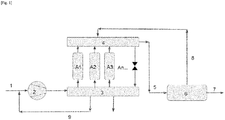
- the method according to the invention will be illustrated with the aid of [ Fig. 1 ].
- the gas feed stream 1 comprising at least methane, carbon dioxide and volatile organic compounds (VOC) is compressed in the compressor 2 to a pressure of between 8 and 15 barg.
- the compressed gas stream is introduced successively according to the pressure cycle mentioned above into the adsorbers A1, A2 and A3.
- These three adsorbers comprising at least one adsorbent making it possible to eliminate at least part of the VOCs, the VOCs are eliminated at least in part from the gas stream.
- a gas stream 5 enriched in methane and carbon dioxide is recovered at the outlet from the adsorbers by means of a second set of valves 4.
- the methane and carbon dioxide from the gas stream 5 are separated in the membrane separation unit 6.
- a retentate 7 rich in methane and a permeate 8 rich in carbon dioxide are recovered.
- the permeate 8 rich in carbon dioxide is recycled as purge gas in the adsorbers A1, A2 and A3 via the second set of valves 4.
- said permeate 8 bypasses the adsorbers via a bypass valve.
- the permeate 8 is then sent directly to the vent or to a thermal oxidizer.
- the permeate leaving the adsorption unit is burned in a thermal oxidator at atmospheric pressure or is sent to the vent of the installation.
- the purge gases are not used to regenerate the adsorbents, they are recycled upstream of the compressor 9.
- the adsorbers A1, A2, and A3 comprise five layers of adsorbents: first layer of adsorbent serving to support the following adsorbents, second layer of alumina activated to dry the gas stream, the third layer of alumina activated to fix organic compounds such as mercaptans, sulphites, tiophenes, fourth layer of adsorbents to remove COS and H2S, fifth layer to fix components Heavy BTEX and CnHm hydrocarbons.
- the [ Fig. 2 ] gives an example of an adsorber comprising these cin layers of adsorbents.
Abstract
Installation pour le traitement d'un flux gazeux d'alimentation (1) comprenant au moins du méthane, du dioxyde de carbone et des composés organiques volatiles (COV), pour produire un flux gazeux enrichi en méthane comprenant dans le sens de circulation du flux gazeux d'alimentation :a) au moins un compresseur (2) permettant d'augmenter la pression du flux gazeux d'alimentation à une pression comprise entre 8 et 15 barg,b) au moins une unité d'adsorption comprenant au moins trois adsorbeurs A1, A2 et A3 qui suivent chacun en décalage de phase un cycle de pression et qui contiennent un adsorbant permettant d'éliminer au moins une partie des COV,c) au moins une unité de séparation par membrane (6) permettant de recevoir le flux gazeux (5) sortant des adsorbeurs et de produire un perméat (8) enrichi en dioxyde de carbone et un rétentat enrichi (7) en méthane,d) un moyen de mesure de la pression du flux gazeux entrant dans l'unité de séparation par membrane et/ou un moyen de mesure de la concentration en méthane dans ce même flux et/ou un moyen de mesure de la pression dans chacun des adsorbeurs,e) un moyen de comparaison de la mesure prise avec une valeur cible, etf) un moyen d'ajustement de l'écoulement du flux gazeux d'alimentation.Installation for the treatment of a feed gas stream (1) comprising at least methane, carbon dioxide and volatile organic compounds (VOCs), to produce a gas stream enriched in methane comprising in the direction of flow of the flow feed gas: a) at least one compressor (2) for increasing the pressure of the feed gas stream to a pressure between 8 and 15 barg, b) at least one adsorption unit comprising at least three adsorbers A1, A2 and A3 which each follow a pressure cycle in phase shift and which contain an adsorbent making it possible to eliminate at least part of the VOCs, c) at least one membrane separation unit (6) making it possible to receive the flow gas (5) leaving the adsorbers and producing a permeate (8) enriched in carbon dioxide and a retentate enriched (7) in methane, d) a means for measuring the pressure of the gas flow entering the separation unit by membrane and / or a means of measuring the co ncentration of methane in this same flow and / or a means of measuring the pressure in each of the adsorbers, e) a means of comparing the measurement taken with a target value, and f) a means of adjusting the flow of the flow feed gas.
Description
La présente invention est relative à une installation et un procédé pour le traitement d'un flux gazeux d'alimentation comprenant au moins du méthane, du dioxyde de carbone et des composés organiques volatiles (COV), pour produire un flux gazeux enrichi en méthane. Elle concerne en particulier l'épuration de biogaz, dans le but de produire du biométhane conforme aux spécifications pour injection dans un réseau de gaz naturel.The present invention relates to an installation and a method for treating a feed gas stream comprising at least methane, carbon dioxide and volatile organic compounds (VOCs), to produce a gas stream enriched in methane. It relates in particular to the purification of biogas, with the aim of producing biomethane conforming to specifications for injection into a natural gas network.
Le biogaz est le gaz produit lors de la dégradation de matières organiques en l'absence d'oxygène (fermentation anaérobie) encore appelée méthanisation. Il peut s'agir d'une dégradation naturelle - on l'observe ainsi dans les marais ou les décharges d'ordures ménagères - mais la production de biogaz peut aussi résulter de la méthanisation de déchets dans un réacteur dédié, appelé méthaniseur ou digesteur.Biogas is the gas produced during the degradation of organic matter in the absence of oxygen (anaerobic fermentation) also called methanization. It can be a matter of natural degradation - we can thus observe it in marshes or household refuse dumps - but the production of biogas can also result from the methanization of waste in a dedicated reactor, called a methanizer or digester.
De par ses constituants principaux - méthane et dioxyde de carbone - le biogaz est un puissant gaz à effet de serre ; il constitue aussi, parallèlement, une source d'énergie renouvelable appréciable dans un contexte de raréfaction des énergies fossiles.Because of its main constituents - methane and carbon dioxide - biogas is a powerful greenhouse gas; at the same time, it is also a significant source of renewable energy in a context of the scarcity of fossil fuels.
Le biogaz contient majoritairement du méthane (CH4) et du dioxyde de carbone (CO2) dans des proportions variables en fonction du mode d'obtention mais également, en moindres proportions de l'eau, de l'azote, de l'hydrogène sulfuré, de l'oxygène, ainsi que des composés organiques autres, à l'état de traces.Biogas mainly contains methane (CH4) and carbon dioxide (CO2) in varying proportions depending on the method of production but also, in smaller proportions, water, nitrogen, hydrogen sulfide, oxygen, as well as other organic compounds, in trace amounts.
Selon les matières organiques dégradées et les techniques utilisées, les proportions des composants diffèrent, mais en moyenne le biogaz comporte, sur gaz sec, de 30 à 75% de méthane, de 15 à 60% de CO2, de 0 à 15% d'azote, de 0 à 5% d'oxygène et des composés traces.Depending on the degraded organic matter and the techniques used, the proportions of the components differ, but on average the biogas comprises, on dry gas, from 30 to 75% of methane, from 15 to 60% of CO2, from 0 to 15% of nitrogen, 0 to 5% oxygen and trace compounds.
Le biogaz est valorisé de différentes manières. Il peut, après un traitement léger, être valorisé à proximité du site de production pour fournir de la chaleur, de l'électricité ou un mélange des deux (la cogénération); la teneur importante en dioxyde de carbone réduit son pouvoir calorifique, augmente les coûts de compression et de transport et limite l'intérêt économique de sa valorisation à cette utilisation de proximité.Biogas is recovered in different ways. It can, after a light treatment, be upgraded near the production site to provide heat, electricity or a mixture of both (cogeneration); the high carbon dioxide content reduces its calorific value, increases compression and transport costs and limits the economic interest of its recovery to this local use.
Une purification plus poussée du biogaz permet sa plus large utilisation, en particulier, une purification poussée du biogaz permet d'obtenir un biogaz épuré aux spécifications du gaz naturel et qui pourra lui être substitué ; le biogaz ainsi purifié est le « biométhane ». Le biométhane complète ainsi les ressources de gaz naturel avec une partie renouvelable produite au cœur des territoires; il est utilisable pour exactement les mêmes usages que le gaz naturel d'origine fossile. Il peut alimenter un réseau de gaz naturel, une station de remplissage pour véhicules, il peut aussi être liquéfié pour être stocké sous forme de gaz naturel liquide (GNL)...Further purification of biogas allows its wider use, in particular, extensive purification of biogas allows to obtain biogas purified to gas specifications natural and which can be substituted for it; the biogas thus purified is “biomethane”. Biomethane thus supplements natural gas resources with a renewable part produced in the heart of the territories; it can be used for exactly the same purposes as natural gas of fossil origin. It can supply a natural gas network, a filling station for vehicles, it can also be liquefied to be stored in the form of liquid natural gas (LNG) ...
Les modes de valorisation du biométhane sont déterminés en fonction des contextes locaux : besoins énergétiques locaux, possibilités de valorisation en tant que biométhane carburant, existence à proximité de réseaux de distribution ou de transport de gaz naturel notamment. Créant des synergies entre les différents acteurs œuvrant sur un territoire (agriculteurs, industriels, pouvoirs publics), la production de biométhane aide les territoires à acquérir une plus grande autonomie énergétique.The methods of recovering biomethane are determined according to local contexts: local energy needs, possibilities of recovery as biomethane fuel, existence near distribution networks or natural gas transport in particular. Creating synergies between the different actors working in a territory (farmers, industrialists, public authorities), the production of biomethane helps the territories to acquire greater energy autonomy.
Plusieurs étapes doivent être franchies entre la collecte du biogaz et l'obtention du biométhane, produit final apte à être comprimé ou liquéfié.Several steps must be taken between collecting the biogas and obtaining the biomethane, the final product capable of being compressed or liquefied.
En particulier, plusieurs étapes sont nécessaires avant le traitement qui vise à séparer le dioxyde de carbone pour produire un courant de méthane purifié. Une première étape consiste à comprimer le biogaz qui a été produit et acheminé à pression atmosphérique, cette compression peut être obtenue - de façon classique - via un compresseur à vis lubrifiée. Les étapes suivantes visent à débarrasser le biogaz des composants corrosifs que sont le sulfure d'hydrogène et les composés organiques volatils (COV), les technologies utilisées sont de façon classique l'adsorption à pression modulée (PSA) et le piégeage sur charbon actif. Vient ensuite l'étape qui consiste à séparer le dioxyde de carbone pour disposer in fine de méthane à la pureté requise pour son usage ultérieur.In particular, several steps are necessary before the treatment which aims to separate the carbon dioxide to produce a stream of purified methane. A first step consists in compressing the biogas which has been produced and conveyed at atmospheric pressure, this compression can be obtained - in a conventional manner - via a lubricated screw compressor. The following steps aim to rid the biogas of corrosive components such as hydrogen sulphide and volatile organic compounds (VOCs), the technologies used are conventionally pressure modulated adsorption (PSA) and trapping on activated carbon. Next comes the step which consists in separating the carbon dioxide in order to ultimately dispose of methane at the purity required for its subsequent use.
Le dioxyde de carbone est un contaminant typiquement présent dans le gaz naturel dont il est courant de devoir le débarrasser. Des technologies variées sont utilisées pour cela en fonction des situations; parmi celles-ci, la technologie membranaire est particulièrement performante lorsque la teneur en CO2 est élevée ; elle est donc particulièrement performante pour séparer le CO2 présent dans le biogaz, et en particulier dans le gaz de décharge.Carbon dioxide is a typical contaminant found in natural gas that it is common to have to get rid of. Various technologies are used for this depending on the situation; among these, membrane technology is particularly efficient when the CO2 content is high; it is therefore particularly efficient for separating the CO2 present in the biogas, and in particular in the landfill gas.
Les procédés membranaires de séparation de gaz utilisés pour la purification d'un gaz, qu'ils utilisent un ou plusieurs étages de membranes doivent permettre la production d'un gaz à la qualité requise, pour un faible coût, tout en minimisant les pertes du gaz que l'on souhaite valoriser. Ainsi, dans le cas de l'épuration du biogaz, la séparation effectuée est principalement une séparation CH4/CO2, devant permettre la production d'un gaz contenant en fonction de son utilisation plus de 85% de CH4, de préférence plus de 95% de CO2, plus préférentiellement plus de 97,5% de CH4, tout en minimisant les pertes de CH4 dans le gaz résiduaire et le coût d'épuration, ce dernier étant pour une part importante lié à la consommation électrique du dispositif de compression du gaz en amont des membranes.The membrane gas separation processes used for the purification of a gas, whether they use one or more membrane stages, must allow the production of a gas of the required quality, at low cost, while minimizing losses of the gas. gas that we want to recover. Thus, in the case of biogas purification, the separation carried out is mainly a CH4 / CO2 separation, to allow the production of a gas containing, depending on its use, more than 85% of CH4, preferably more than 95% of CO2, more preferably more than 97.5% of CH4, while minimizing the losses of CH4 in the waste gas and the cost of purification, the latter being for a large part linked to the electrical consumption of the gas compression device upstream of the membranes.
Il est préférable que les installations permettant la production d'un flux gazeux enrichi en méthane puissent contrôler la perte de méthane.It is preferable that the installations allowing the production of a gas stream enriched in methane can control the loss of methane.
Partant de là, un problème qui se pose est de fournir une installation permettant l'obtention d'un courant de méthane à concentration constante.On this basis, a problem which arises is to provide an installation enabling a stream of methane to be obtained at constant concentration.
Une solution de la présente invention est une installation pour le traitement d'un flux gazeux d'alimentation 1 comprenant au moins du méthane, du dioxyde de carbone et des composés organiques volatiles (COV), pour produire un flux gazeux enrichi en méthane comprenant dans le sens de circulation du flux gazeux d'alimentation :
- a) au moins un
compresseur 2 permettant d'augmenter la pression du flux gazeux d'alimentation à une pression comprise entre 8 et 15 barg, - b) au moins une unité d'adsorption comprenant au moins trois adsorbeurs A1, A2 et A3 qui suivent chacun en décalage de phase un cycle de pression et qui contiennent un adsorbant permettant d'éliminer au moins une partie des COV,
- c) au moins une unité de séparation par
membrane 6 permettant de recevoir le flux gazeux 5 sortant des adsorbeurs et de produire unperméat 8 enrichi en dioxyde de carbone et un rétentat enrichi 7 en méthane, - d) un moyen de mesure de la pression du flux gazeux entrant dans l'unité de séparation par membrane et/ou un moyen de mesure de la concentration en méthane dans ce même flux et/ou un moyen de mesure de la pression dans chacun des adsorbeurs,
- e) un moyen de comparaison de la mesure prise avec une valeur cible, et
- f) un moyen d'ajustement de l'écoulement du flux gazeux d'alimentation.
- a) at least one
compressor 2 making it possible to increase the pressure of the supply gas flow to a pressure between 8 and 15 barg, - b) at least one adsorption unit comprising at least three adsorbers A1, A2 and A3 which each follow a pressure cycle in phase shift and which contain an adsorbent making it possible to remove at least part of the VOCs,
- c) at least one
membrane separation unit 6 making it possible to receive thegas flow 5 exiting the adsorbers and to produce apermeate 8 enriched in carbon dioxide and a retentate enriched 7 in methane, - d) a means for measuring the pressure of the gas flow entering the membrane separation unit and / or a means for measuring the methane concentration in this same flow and / or a means for measuring the pressure in each of the adsorbers,
- e) a means of comparing the measurement taken with a target value, and
- f) means for adjusting the flow of the feed gas stream.
De préférence l'unité d'adsorption sera de type PSA.Preferably the adsorption unit will be of the PSA type.
Selon le cas, l'installation selon l'invention peut présenter une ou plusieurs des caractéristiques suivantes :
- elle comprend au moins un jeu de
vannes 3 en entrée des adsorbeurs et un jeu devannes 4 en sortie des adsorbeurs et ces jeux de vannes constituent au moins une partie du moyen d'ajustement de l'écoulement du flux gazeux d'alimentation. - elle comprend un moyen de recycle d'au moins une partie du perméat dans au moins un des adsorbeurs.
- elle comprend un moyen de contournement du moyen de recycle.
- l'unité de séparation par membrane comprend : une première sous-unité de séparation par membrane permettant de recevoir le flux gazeux sortant des adsorbeurs et de produire un premier perméat enrichi en dioxyde de carbone et un premier rétentat enrichi en méthane, une seconde sous-unité de séparation par membrane permettant de recevoir le premier rétentat et de produire un second perméat enrichi en dioxyde de carbone et un second rétentat enrichi en méthane, une troisième sous-unité de séparation par membrane permettant de recevoir le premier perméat et de produire un troisième rétentat (9) enrichi en méthane et un troisième perméat enrichi en CO2.
- it comprises at least one set of
valves 3 at the inlet of the adsorbers and a set ofvalves 4 at the outlet of the adsorbers and these sets of valves constitute at least part of the means for adjusting the flow of the gas feed stream. - it comprises a means for recycling at least part of the permeate in at least one of the adsorbers.
- it comprises a means of bypassing the recycling means.
- the membrane separation unit comprises: a first membrane separation sub-unit making it possible to receive the gas flow leaving the adsorbers and to produce a first permeate enriched in carbon dioxide and a first retentate enriched in methane, a second sub- membrane separation unit making it possible to receive the first retentate and to produce a second permeate enriched in carbon dioxide and a second retentate enriched in methane, a third membrane separation sub-unit making it possible to receive the first permeate and produce a third retentate (9) enriched in methane and a third permeate enriched in CO2.
La présente invention a également pour objet un procédé de traitement d'un flux gazeux d'alimentation comprenant au moins du méthane, du dioxyde de carbone et des composés organiques volatiles (COV), pour produire un flux gazeux enrichi en méthane, mettant en œuvre une installation selon l'invention et comprenant :
- i. une étape de compression du flux gazeux d'alimentation à une pression comprise entre 8 et 15 barg
- ii. une étape d'élimination d'au moins une partie des COV par adsorption du flux gazeux comprimé dans l'unité d'adsorption,
- iii. une étape de séparation du dioxyde de carbone et du méthane dans l'unité de séparation par membrane,
- iv. une étape de mesure de la pression du flux gazeux entrant dans l'unité de séparation par membrane et/ou de mesure de la concentration en méthane dans ce même flux et/ou de mesure de la pression dans chacun des adsorbeurs,
- v. une étape de comparaison de la mesure prise à l'étape iv avec une valeur cible, et
- vi. en cas d'écart entre la mesure prise et la valeur cible une étape de modification de l'écoulement du flux gazeux d'alimentation afin d'obtenir la valeur cible.
- i. a step of compressing the supply gas flow to a pressure between 8 and 15 barg
- ii. a step of eliminating at least part of the VOCs by adsorption of the gas stream compressed in the adsorption unit,
- iii. a step for separating carbon dioxide and methane in the membrane separation unit,
- iv. a step of measuring the pressure of the gas flow entering the membrane separation unit and / or measuring the methane concentration in this same flow and / or measuring the pressure in each of the adsorbers,
- v. a step of comparing the measurement taken in step iv with a target value, and
- vi. in the event of a difference between the measurement taken and the target value, a step of modifying the flow of the gas feed stream in order to obtain the target value.
Notons que les étapes iv à vi permettent d'obtenir un flux de méthane à concentration constante.Note that steps iv to vi make it possible to obtain a methane flow at constant concentration.
Selon le cas le procédé peut présenter un ou plusieurs des caractéristiques suivantes :
- les étapes i à vi sont réalisées en continu,
- à l'étape ii chaque adsorbeur de l'unité d'adsorption va suivre en décalage de phase le cycle de pression comprenant les périodes successives suivantes :
- a. adsorption au cours de laquelle le gaz d'alimentation est introduit par une des extrémités de l'adsorbeur et au moins une partie des COV sont adsorbés par l'adsorbant,
- b. dépressurisation au cours de laquelle l'adsorbeur qui n'est plus alimenté en gaz d'alimentation est évacué par au moins une de ses extrémités d'une partie des COV contenus dans l'adsorbant,
- c. élution au cours de laquelle un gaz de purge circule à travers le lit d'adsorbant afin d'aider à la désorption des COV,
- d. repressurisation au cours de laquelle l'adsorbeur est au moins partiellement repressurisé.
- à l'étape c. le gaz de purge est constitué d'au moins une partie du perméat enrichi en dioxyde de carbone issu de l'unité de séparation par membrane,
- le gaz de purge sortant de l'unité d'adsorption est brûlé dans un oxidateur thermique à pression atmosphérique ou est envoyé à l'évent de l'installation.
- le perméat enrichi en dioxyde de carbone est envoyé directement à l'évent ou dans un oxidateur thermique lors des périodes pendant lesquelles aucun adsorbeur n'est traversé par ledit perméat.
- le cycle de pression comprend une étape de temps mort.
- la dépressurisation commence par une dépressurisation à co-courant par équilibrage de pressions avec un autre adsorbeur.
- les étapes iv, v et vi sont réalisées automatiquement par des moyens de transmission de données et de traitement de données.
- le flux gazeux d'alimentation est du biogaz.
- steps i to vi are carried out continuously,
- in step ii, each adsorber of the adsorption unit will follow the pressure cycle in phase shift comprising the following successive periods:
- at. adsorption during which the feed gas is introduced through one of the ends of the adsorber and at least part of the VOCs are adsorbed by the adsorbent,
- b. depressurization during which the adsorber which is no longer supplied with feed gas is discharged from at least one of its ends of a portion of the VOCs contained in the adsorbent,
- vs. elution in which a purge gas flows through the adsorbent bed to aid in the desorption of VOCs,
- d. repressurization during which the adsorber is at least partially repressurized.
- in step c. the purge gas consists of at least part of the permeate enriched in carbon dioxide from the membrane separation unit,
- the purge gas leaving the adsorption unit is burned in a thermal oxidator at atmospheric pressure or is sent to the installation vent.
- the permeate enriched in carbon dioxide is sent directly to the vent or to a thermal oxidizer during periods during which no adsorber is crossed by said permeate.
- the pressure cycle includes a dead time step.
- depressurization begins with cocurrent depressurization by pressure balancing with another adsorber.
- steps iv, v and vi are performed automatically by data transmission and data processing means.
- the feed gas flow is biogas.
De manière générale, un procédé par adsorption en phase gazeuse permet de séparer une ou plusieurs molécules d'un mélange gazeux les contenant, en exploitant la différence d'affinité d'un ou plusieurs adsorbants pour les différentes molécules constitutives du mélange. L'affinité d'un adsorbant pour une molécule dépend d'une part de la structure et la composition de l'adsorbant et d'autre part des propriétés de la molécule, en particulier sa taille, sa structure électronique et ses moments multipolaires. Un adsorbant peut être par exemple une zéolite, un charbon actif, une alumine activée éventuellement dopée, un gel de silice, un tamis moléculaire carboné, une structure métallo-organique, un oxyde ou hydroxyde de métaux alcalins ou alcalino-terreux, ou une structure poreuse contenant de préférence une substance capable de réagir réversiblement avec les molécules, substance telle que amines, solvants physique, complexants métalliques, oxydes ou hydroxydes métalliques par exemple.In general, a gas phase adsorption process makes it possible to separate one or more molecules from a gas mixture containing them, by exploiting the difference in affinity of one or more adsorbents for the different molecules constituting the mixture. The affinity of an adsorbent for a molecule depends on the one hand on the structure and composition of the adsorbent and on the other hand on the properties of the molecule, in particular its size, its electronic structure and its multipolar moments. An adsorbent can be for example a zeolite, an activated carbon, an activated alumina optionally doped, a gel of silica, a carbon molecular sieve, a metallo-organic structure, an oxide or hydroxide of alkali or alkaline earth metals, or a porous structure preferably containing a substance capable of reacting reversibly with the molecules, substance such as amines, physical solvents, metal complexing agents, metal oxides or hydroxides for example.
Les matériaux adsorbants les plus classiques sont sous forme de particules (billes, bâtonnets, concassés...) mais existent également sous forme structurée tels les monolithes, roues, contacteurs à passages parallèle, tissus, fibres...The most traditional adsorbent materials are in the form of particles (balls, sticks, crushed pieces, etc.) but also exist in structured form such as monoliths, wheels, contactors with parallel passages, fabrics, fibers, etc.
On peut distinguer 3 grandes familles de procédé par adsorption : les procédés à charge perdue, les procédés TSA (Température Swing Adsorption = Adsorption à variation de pression) et enfin les procédés PSA (Pressure Swing Adsorption = Adsorption à variation de pression).We can distinguish 3 main families of adsorption process: lost charge processes, TSA (Temperature Swing Adsorption = Pressure Variation Adsorption) processes and finally PSA (Pressure Swing Adsorption = Pressure Variation Adsorption) processes.
Dans les procédés à charge perdue - on parle souvent dans ce cas de lit de garde- on met en place une nouvelle charge lorsque celle en cours d'utilisation est saturée par les impuretés ou plus généralement quand elle ne peut plus jouer son rôle de protection de manière suffisante.In lost charge processes - in this case we often speak of a guard bed - a new charge is put in place when the one in use is saturated with impurities or more generally when it can no longer play its protective role. sufficiently.
Dans les procédés de type TSA, l'adsorbant en fin d'utilisation est régénéré in situ, c'est-à-dire que les impuretés arrêtées sont évacuées afin que le dit adsorbant récupère l'essentiel de ses capacités d'adsorption et puisse recommencer un cycle d'épuration, l'effet de régénération essentiel étant dû à une élévation de température.In TSA-type processes, the adsorbent at the end of use is regenerated in situ, that is to say that the stopped impurities are removed so that said adsorbent recovers most of its adsorption capacities and can restart a purification cycle, the essential regeneration effect being due to a rise in temperature.
Enfin, dans les procédés de type PSA, l'adsorbant en fin de phase de production est régénéré par la désorption des impuretés obtenue au moyen d'une baisse de leur pression partielle. Cette baisse de pression peut être obtenue par une baisse de la pression totale et/ ou par balayage avec un gaz exempt ou contenant peu d'impuretés.Finally, in PSA type processes, the adsorbent at the end of the production phase is regenerated by the desorption of the impurities obtained by means of a drop in their partial pressure. This pressure drop can be obtained by a drop in the total pressure and / or by flushing with a gas free or containing few impurities.
On s'intéresse ici à ce dernier type de procédé par PSA.We are interested here in this last type of process by PSA.
Dans le cadre de la présente invention, on désigne par les termes PSA tout procédé d'épuration ou de séparation de gaz mettant en œuvre une variation cyclique de la pression que voit l'adsorbant entre une pression haute, dite pression d'adsorption, et une pression basse, dite pression de régénération. Ainsi, cette appellation générique de PSA est employée indifféremment pour désigner les procédés cycliques suivants, auxquels il est aussi courant de donner des noms plus spécifiques en fonction des niveaux de pression mis en jeu ou du temps nécessaire à un adsorbeur pour revenir à son point initial (temps de cycle):
- Les procédés VSA dans lesquels l'adsorption s'effectue sensiblement à la pression atmosphérique, préférentiellement entre 0.95 et 1.25 bar abs et la pression de désorption est inférieure à la pression atmosphérique, typiquement de 50 à 400 mbar abs
- Les procédés MPSA ou VPSA dans lesquels l'adsorption s'effectue à une pression haute supérieure à la pression atmosphérique, typiquement entre 1.4
et 6 bar abs, et la désorption à une pression basse inférieure à la pression atmosphérique, généralement comprise entre 200 et 600 mbar abs - Les procédés PSA proprement dits dans lesquels la pression haute est sensiblement supérieure à la pression atmosphérique,
typiquement entre 3 et 50 bar abs et la pression basse sensiblement égale ou supérieure à la pression atmosphérique,généralement entre 1et 9 bar abs. - Les procédés RPSA (Rapid PSA) pour lesquels la durée du cycle de pression est typiquement inférieure à la minute
- Les procédés URPSA (Ultra Rapid PSA) pour lesquels la durée du cycle de pression est de l'ordre de quelques secondes maximum.
- VSA processes in which the adsorption takes place substantially at atmospheric pressure, preferably between 0.95 and 1.25 bar abs and the desorption pressure is less than atmospheric pressure, typically from 50 to 400 mbar abs
- MPSA or VPSA processes in which the adsorption takes place at a high pressure greater than atmospheric pressure, typically between 1.4 and 6 bar abs, and desorption at a low pressure below atmospheric pressure, generally between 200 and 600 mbar abs
- The actual PSA processes in which the high pressure is substantially greater than atmospheric pressure, typically between 3 and 50 bar abs and the low pressure substantially equal to or greater than atmospheric pressure, generally between 1 and 9 bar abs.
- RPSA (Rapid PSA) processes for which the duration of the pressure cycle is typically less than a minute
- URPSA (Ultra Rapid PSA) processes for which the duration of the pressure cycle is of the order of a few seconds maximum.
Il convient de noter que ces diverses appellations ne sont pas standardisées et que les limites sont sujettes à variation. On rappelle que sauf avis contraire, l'utilisation du terme PSA recouvre ici toutes ces variantes.It should be noted that these various names are not standardized and that the limits are subject to variation. It is recalled that unless otherwise stated, the use of the term PSA covers all these variants here.
Un adsorbeur va donc commencer une période d'adsorption jusqu'à ce qu'il soit chargé dans le ou les constituants à arrêter à la pression haute puis va être régénéré par dépressurisation et extraction des composés adsorbés avant d'être remis en état pour recommencer une nouvelle période d'adsorption. L'adsorbeur a alors effectué un "cycle de pression" et le principe même du procédé PSA est d'enchaîner ces cycles les uns après les autres ; il s'agit donc d'un procédé cyclique. Le temps que met un adsorbeur pour revenir dans son état initial est appelé temps de cycle. Par principe, chaque adsorbeur suit le même cycle avec un décalage temporel qu'on appelle temps de phase ou plus simplement phase. On a donc la relation : ![]()
![]()
Ce cycle comporte donc généralement des périodes de :
- Production ou Adsorption au cours de laquelle le gaz d'alimentation est introduit par une des extrémités de l'adsorbeur, les composés les plus adsorbables sont adsorbés préférentiellement et le gaz enrichi en les composés les moins adsorbables (gaz produit) est extrait par la seconde extrémité. L'adsorption peut se faire à pression montante, à pression sensiblement constante, voire à pression légèrement descendante. On parle de pression HP (haute pression) pour signifier la pression d'adsorption.
- Dépressurisation au cours de laquelle l'adsorbeur qui n'est plus alimenté en gaz d'alimentation est évacué par au moins une de ses extrémités d'une partie des composés contenus dans l'adsorbant et les volumes libres. En prenant comme référence le sens de circulation du fluide en période d'adsorption, on peut définir des dépressurisations à co-courant, à contre-courant ou simultanément à co et contre-courant.
- Elution ou Purge au cours de laquelle un gaz enrichi en les constituants les moins adsorbables (gaz de purge) circule à travers le lit d'adsorbant afin d'aider à la désorption des composés les plus adsorbables. La Purge se fait généralement à contre-courant.
- Repressurisation au cours de laquelle l'adsorbeur est au moins partiellement repressurisé avant de reprendre une période d'Adsorption. La repressurisation peut se faire à contre-courant et/ou à co-courant.
- Temps mort au cours de laquelle l'adsorbeur reste dans le même état. Ces temps morts peuvent faire partie intégrale du cycle, permettant la synchronisation d'étapes entre adsorbeurs ou faire partie d'une étape qui s'est terminée avant le temps imparti. Les vannes peuvent être fermées ou rester en l'état selon les caractéristiques du cycle.
- Production or Adsorption during which the feed gas is introduced through one of the ends of the adsorber, the most adsorbable compounds are preferentially adsorbed and the gas enriched in the less adsorbable compounds (product gas) is extracted by the second end. The adsorption can take place at rising pressure, at substantially constant pressure, or even at slightly falling pressure. We speak of pressure HP (high pressure) to mean the adsorption pressure.
- Depressurization during which the adsorber which is no longer supplied with feed gas is discharged from at least one of its ends of a portion of the compounds contained in the adsorbent and the free volumes. By taking as a reference the direction of circulation of the fluid during the adsorption period, it is possible to define depressurizations with cocurrent, countercurrent or simultaneously with co and countercurrent.
- Elution or Purge during which a gas enriched in the less adsorbable constituents (purge gas) circulates through the adsorbent bed in order to aid in the desorption of the most adsorbable compounds. The Purge is usually done against the tide.
- Repressurization during which the adsorber is at least partially repressurized before resuming a period of adsorption. Repressurization can be done against the current and / or against the current.
- Dead time during which the adsorber remains in the same state. These dead times can be an integral part of the cycle, allowing the synchronization of steps between adsorbers or be part of a step which ended before the allotted time. The valves can be closed or remain unchanged depending on the characteristics of the cycle.
Lorsque le produit valorisé est constitué par les constituants les plus adsorbables, on peut ajouter une étape dite de Rinse qui consiste à faire circuler à co-courant dans l'adsorbeur un gaz enrichi en les constituants les plus adsorbables avec l'objectif de chasser de l'adsorbant et des volumes morts les composés les moins adsorbables. Cette étape de Rinse peut se faire à toute pression entre la pression haute et la pression basse et utilise généralement une fraction du produit basse pression après compression. Le gaz extrait de l'adsorbeur lors de cette étape peut avoir de nombreuses utilisations (production secondaire de gaz enrichi en les constituants les moins adsorbables, repressurisation, élution, réseau fuel gas...).When the upgraded product consists of the most adsorbable constituents, a so-called Rinse stage can be added which consists of circulating in co-current in the adsorber a gas enriched in the most adsorbable constituents with the objective of removing the adsorbent and dead volumes the least adsorbable compounds. This Rinse step can be done at any pressure between high pressure and low pressure and generally uses a fraction of the low pressure product after compression. The gas extracted from the adsorber during this step can have many uses (secondary production of gas enriched in the less adsorbable constituents, repressurization, elution, fuel gas network, etc.).
Le procédé selon l'invention va être illustré à l'aide de la [
Selon un cas particulier, le flux gazeux d'alimentation comprend :
- de l'eau,
- des composés organiques tels que les mercaptans, les sulfites et les tiophènes
- des COS et/ou H2S, et
- des composants BTEX (Benzène, Toluène, Éthylbenzène et Xylènes) et ou hydrocarbure CnHm lourds.
- some water,
- organic compounds such as mercaptans, sulphites and tiophenes
- COS and / or H2S, and
- BTEX components (Benzene, Toluene, Ethylbenzene and Xylenes) and or heavy CnHm hydrocarbons.
Dans ce cas particulier, les adsorbeurs A1, A2, et A3 comprennent cinq couches d'adsorbants : première couche d'adsorbant servant au support des adsorbants suivant, deuxième couche d'alumine activée pour sécher le flux gazeux, la troisième couche d'alumine activée pour fixer les composés organiques tels que mercaptans, sulfites, tiophènes, quatrième couche d'adsorbants pour enlever les COS et H2S, cinquième couche servant à fixer les composants BTEX et hydrocarbure CnHm lourds. La [
Claims (15)
Applications Claiming Priority (1)
| Application Number | Priority Date | Filing Date | Title |
|---|---|---|---|
| FR1906644A FR3097450B1 (en) | 2019-06-20 | 2019-06-20 | Treatment of a methane stream comprising VOCs and carbon dioxide by combining an adsorption unit and a membrane separation unit |
Publications (1)
| Publication Number | Publication Date |
|---|---|
| EP3756749A1 true EP3756749A1 (en) | 2020-12-30 |
Family
ID=68425013
Family Applications (1)
| Application Number | Title | Priority Date | Filing Date |
|---|---|---|---|
| EP20180080.2A Pending EP3756749A1 (en) | 2019-06-20 | 2020-06-15 | Treatment of a flow of methane comprising voc and carbon dioxide by a combination of an adsorption unit and a unit for separating by membrane |
Country Status (4)
| Country | Link |
|---|---|
| US (1) | US11351499B2 (en) |
| EP (1) | EP3756749A1 (en) |
| CN (1) | CN112107963A (en) |
| FR (1) | FR3097450B1 (en) |
Families Citing this family (3)
| Publication number | Priority date | Publication date | Assignee | Title |
|---|---|---|---|---|
| EP3981500B1 (en) * | 2020-10-09 | 2023-06-21 | 12M Invent GmbH | A gas seperation system and gas seperation method comprising a membrane system having a control valve |
| FR3120802A1 (en) * | 2021-03-22 | 2022-09-23 | L'air Liquide Societe Anonyme Pour L'etude Et L'exploitation Des Procedes Georges Claude | Installation and process for obtaining biomethane in accordance with the specificities of a transport network |
| CN116651140A (en) * | 2023-05-19 | 2023-08-29 | 湖南比扬医疗科技有限公司 | Oxygen plant with pressure self-regulation and pressure self-regulation method |
Citations (4)
| Publication number | Priority date | Publication date | Assignee | Title |
|---|---|---|---|---|
| WO2014104196A1 (en) * | 2012-12-28 | 2014-07-03 | 大阪瓦斯株式会社 | Gas refining apparatus |
| WO2017109305A1 (en) * | 2015-12-24 | 2017-06-29 | Waga Energy | Method for producing biomethane by purifying biogas from non-hazardous waste storage facilities and facility for implementing the method |
| EP3369473A1 (en) * | 2017-03-02 | 2018-09-05 | L'air Liquide Societe Anonyme Pour L'etude Et L'exploitation Des Procedes Georges Claude | Facility and method for treatment of a feed gas stream comprising methane and carbon dioxide by membrane permeation |
| EP3437713A1 (en) * | 2016-03-31 | 2019-02-06 | Osaka Gas Co., Ltd. | Pressure-swing-adsorption gas producing apparatus |
Family Cites Families (2)
| Publication number | Priority date | Publication date | Assignee | Title |
|---|---|---|---|---|
| US7025803B2 (en) * | 2002-12-02 | 2006-04-11 | L'Air Liquide Societe Anonyme A Directoire et Counsel de Surveillance Pour L'Etude et L'Exploration des Procedes Georges Claude | Methane recovery process |
| BR112013000082B1 (en) * | 2010-07-01 | 2023-10-31 | Evonik Operations Gmbh | PROCESS FOR SEPARATING A RAW GAS FLOW |
-
2019
- 2019-06-20 FR FR1906644A patent/FR3097450B1/en active Active
-
2020
- 2020-06-15 EP EP20180080.2A patent/EP3756749A1/en active Pending
- 2020-06-18 US US16/905,567 patent/US11351499B2/en active Active
- 2020-06-19 CN CN202010566872.XA patent/CN112107963A/en active Pending
Patent Citations (4)
| Publication number | Priority date | Publication date | Assignee | Title |
|---|---|---|---|---|
| WO2014104196A1 (en) * | 2012-12-28 | 2014-07-03 | 大阪瓦斯株式会社 | Gas refining apparatus |
| WO2017109305A1 (en) * | 2015-12-24 | 2017-06-29 | Waga Energy | Method for producing biomethane by purifying biogas from non-hazardous waste storage facilities and facility for implementing the method |
| EP3437713A1 (en) * | 2016-03-31 | 2019-02-06 | Osaka Gas Co., Ltd. | Pressure-swing-adsorption gas producing apparatus |
| EP3369473A1 (en) * | 2017-03-02 | 2018-09-05 | L'air Liquide Societe Anonyme Pour L'etude Et L'exploitation Des Procedes Georges Claude | Facility and method for treatment of a feed gas stream comprising methane and carbon dioxide by membrane permeation |
Also Published As
| Publication number | Publication date |
|---|---|
| CN112107963A (en) | 2020-12-22 |
| US20200398217A1 (en) | 2020-12-24 |
| FR3097450A1 (en) | 2020-12-25 |
| US11351499B2 (en) | 2022-06-07 |
| FR3097450B1 (en) | 2021-11-19 |
Similar Documents
| Publication | Publication Date | Title |
|---|---|---|
| EP3393621B1 (en) | Method for producing biomethane by purifying biogas from non-hazardous waste storage facilities and facility for implementing the method | |
| EP3756749A1 (en) | Treatment of a flow of methane comprising voc and carbon dioxide by a combination of an adsorption unit and a unit for separating by membrane | |
| FR2916363A1 (en) | PROCESS FOR PURIFYING A CPSA GAS WITH TWO REGENERATION BEARINGS AND PURIFICATION UNIT FOR CARRYING OUT SAID METHOD | |
| FR2918578A1 (en) | PROCESS FOR PURIFYING GAS CONTAINING CO2 | |
| EP2376373A1 (en) | Production of hydrogen from a reforming gas and simultaneous capture of co2 co-product | |
| EP2106284A2 (en) | Hydrogen adsorption purification method with co-generation of a pressurised co<sb>2</sb>flow | |
| FR2836061A1 (en) | PROCESS FOR TREATING A GAS MIXTURE COMPRISING HYDROGEN AND HYDROGEN SULFIDE | |
| FR2788051A1 (en) | PROCESS AND PLANT FOR THE PRODUCTION OF CARBON MONOXIDE OR A CO / H2 MIXTURE | |
| FR2917304A1 (en) | PSA METHOD FOR RECOVERING SPECIFIC COMPOUNDS | |
| EP2709745B1 (en) | Method for purification by means of adsorption with regeneration using a gas containing an undesired component in the purified gas | |
| FR3035337B1 (en) | PROCESS FOR PURIFYING A GAS COMPRISING METHANE | |
| EP2179776B1 (en) | Re-pressurisation of a CO2-VSA treating a gaseous mix containing a fuel | |
| EP4062998A1 (en) | Installation and method for obtaining biomethane in accordance with the specific features of a transport network | |
| FR2836058A1 (en) | Process for separating gaseous mixture, e.g. refinery feed flow, involves simultaneous use of permeation treatment unit and adsorption unit | |
| WO2003070358A1 (en) | Method and unit for the production of hydrogen from a hydrogen-rich feed gas | |
| FR3110722A3 (en) | Management method of a gas treatment unit by pressure modulation adsorption | |
| FR2892322A1 (en) | Pressure swing adsorption for producing hydrogen enriched gaseous fraction from feedstock gas, comprises introducing the gas into an adsorber to adsorb the gas in a high pressure of cycle, and terminating the introduced gas in the adsorber | |
| FR2758475A1 (en) | Process for manufacturing high purity hydrogen | |
| FR3120232A3 (en) | Ultra-purification process of a fraction of hydrogen from a PSA H2 | |
| EP3756750A1 (en) | Installation for the treatment of a flow of methane and carbon dioxide by means of a vane compressor and a membrane separator unit | |
| EP3892357A1 (en) | System for treating biogas by membrane permeation with adaptation of the membrane surface according to the pressure of biogas | |
| FR3120546A3 (en) | Method for treating a gas by pressure swing adsorption with low elution ratio | |
| FR2837722A1 (en) | Process for the purification of hydrogen contained in a low hydrogen-content gaseous mixture by a PSA technique with two adsorbents | |
| WO2008043897A2 (en) | Process for producing hydrogen using a column with simulated mobile bed | |
| FR2836062A1 (en) | Production of hydrogen from a hydrogen-rich feed gas by pressure swing adsorption comprises recycling compressed effluents from adsorbers in regeneration phase to adsorbers in absorption phase |
Legal Events
| Date | Code | Title | Description |
|---|---|---|---|
| PUAI | Public reference made under article 153(3) epc to a published international application that has entered the european phase |
Free format text: ORIGINAL CODE: 0009012 |
|
| STAA | Information on the status of an ep patent application or granted ep patent |
Free format text: STATUS: THE APPLICATION HAS BEEN PUBLISHED |
|
| AK | Designated contracting states |
Kind code of ref document: A1 Designated state(s): AL AT BE BG CH CY CZ DE DK EE ES FI FR GB GR HR HU IE IS IT LI LT LU LV MC MK MT NL NO PL PT RO RS SE SI SK SM TR |
|
| AX | Request for extension of the european patent |
Extension state: BA ME |
|
| STAA | Information on the status of an ep patent application or granted ep patent |
Free format text: STATUS: REQUEST FOR EXAMINATION WAS MADE |
|
| RIN1 | Information on inventor provided before grant (corrected) |
Inventor name: BARRAUD, FRANCOIS Inventor name: GUILLIN, MICHAEL Inventor name: ROHMER, THOMAS |
|
| 17P | Request for examination filed |
Effective date: 20210630 |
|
| RBV | Designated contracting states (corrected) |
Designated state(s): AL AT BE BG CH CY CZ DE DK EE ES FI FR GB GR HR HU IE IS IT LI LT LU LV MC MK MT NL NO PL PT RO RS SE SI SK SM TR |
|
| RIN1 | Information on inventor provided before grant (corrected) |
Inventor name: BARRAUD, FRANCOIS Inventor name: GUILLIN, MICHAEL Inventor name: ROHMER, THOMAS |