EP3756626B1 - Subtalar joint implant - Google Patents
Subtalar joint implant Download PDFInfo
- Publication number
- EP3756626B1 EP3756626B1 EP20176094.9A EP20176094A EP3756626B1 EP 3756626 B1 EP3756626 B1 EP 3756626B1 EP 20176094 A EP20176094 A EP 20176094A EP 3756626 B1 EP3756626 B1 EP 3756626B1
- Authority
- EP
- European Patent Office
- Prior art keywords
- region
- implant
- talar
- calcaneal
- component
- Prior art date
- Legal status (The legal status is an assumption and is not a legal conclusion. Google has not performed a legal analysis and makes no representation as to the accuracy of the status listed.)
- Active
Links
Images




Classifications
-
- A—HUMAN NECESSITIES
- A61—MEDICAL OR VETERINARY SCIENCE; HYGIENE
- A61F—FILTERS IMPLANTABLE INTO BLOOD VESSELS; PROSTHESES; DEVICES PROVIDING PATENCY TO, OR PREVENTING COLLAPSING OF, TUBULAR STRUCTURES OF THE BODY, e.g. STENTS; ORTHOPAEDIC, NURSING OR CONTRACEPTIVE DEVICES; FOMENTATION; TREATMENT OR PROTECTION OF EYES OR EARS; BANDAGES, DRESSINGS OR ABSORBENT PADS; FIRST-AID KITS
- A61F2/00—Filters implantable into blood vessels; Prostheses, i.e. artificial substitutes or replacements for parts of the body; Appliances for connecting them with the body; Devices providing patency to, or preventing collapsing of, tubular structures of the body, e.g. stents
- A61F2/02—Prostheses implantable into the body
- A61F2/30—Joints
- A61F2/42—Joints for wrists or ankles; for hands, e.g. fingers; for feet, e.g. toes
- A61F2/4202—Joints for wrists or ankles; for hands, e.g. fingers; for feet, e.g. toes for ankles
-
- A—HUMAN NECESSITIES
- A61—MEDICAL OR VETERINARY SCIENCE; HYGIENE
- A61F—FILTERS IMPLANTABLE INTO BLOOD VESSELS; PROSTHESES; DEVICES PROVIDING PATENCY TO, OR PREVENTING COLLAPSING OF, TUBULAR STRUCTURES OF THE BODY, e.g. STENTS; ORTHOPAEDIC, NURSING OR CONTRACEPTIVE DEVICES; FOMENTATION; TREATMENT OR PROTECTION OF EYES OR EARS; BANDAGES, DRESSINGS OR ABSORBENT PADS; FIRST-AID KITS
- A61F2/00—Filters implantable into blood vessels; Prostheses, i.e. artificial substitutes or replacements for parts of the body; Appliances for connecting them with the body; Devices providing patency to, or preventing collapsing of, tubular structures of the body, e.g. stents
- A61F2/02—Prostheses implantable into the body
- A61F2/30—Joints
- A61F2002/30001—Additional features of subject-matter classified in A61F2/28, A61F2/30 and subgroups thereof
- A61F2002/30108—Shapes
- A61F2002/30199—Three-dimensional shapes
- A61F2002/30205—Three-dimensional shapes conical
- A61F2002/3021—Three-dimensional shapes conical frustoconical
-
- A—HUMAN NECESSITIES
- A61—MEDICAL OR VETERINARY SCIENCE; HYGIENE
- A61F—FILTERS IMPLANTABLE INTO BLOOD VESSELS; PROSTHESES; DEVICES PROVIDING PATENCY TO, OR PREVENTING COLLAPSING OF, TUBULAR STRUCTURES OF THE BODY, e.g. STENTS; ORTHOPAEDIC, NURSING OR CONTRACEPTIVE DEVICES; FOMENTATION; TREATMENT OR PROTECTION OF EYES OR EARS; BANDAGES, DRESSINGS OR ABSORBENT PADS; FIRST-AID KITS
- A61F2/00—Filters implantable into blood vessels; Prostheses, i.e. artificial substitutes or replacements for parts of the body; Appliances for connecting them with the body; Devices providing patency to, or preventing collapsing of, tubular structures of the body, e.g. stents
- A61F2/02—Prostheses implantable into the body
- A61F2/30—Joints
- A61F2002/30001—Additional features of subject-matter classified in A61F2/28, A61F2/30 and subgroups thereof
- A61F2002/30108—Shapes
- A61F2002/30199—Three-dimensional shapes
- A61F2002/30205—Three-dimensional shapes conical
- A61F2002/30217—Three-dimensional shapes conical hollow cones, e.g. tubular-like cones
-
- A—HUMAN NECESSITIES
- A61—MEDICAL OR VETERINARY SCIENCE; HYGIENE
- A61F—FILTERS IMPLANTABLE INTO BLOOD VESSELS; PROSTHESES; DEVICES PROVIDING PATENCY TO, OR PREVENTING COLLAPSING OF, TUBULAR STRUCTURES OF THE BODY, e.g. STENTS; ORTHOPAEDIC, NURSING OR CONTRACEPTIVE DEVICES; FOMENTATION; TREATMENT OR PROTECTION OF EYES OR EARS; BANDAGES, DRESSINGS OR ABSORBENT PADS; FIRST-AID KITS
- A61F2/00—Filters implantable into blood vessels; Prostheses, i.e. artificial substitutes or replacements for parts of the body; Appliances for connecting them with the body; Devices providing patency to, or preventing collapsing of, tubular structures of the body, e.g. stents
- A61F2/02—Prostheses implantable into the body
- A61F2/30—Joints
- A61F2002/30001—Additional features of subject-matter classified in A61F2/28, A61F2/30 and subgroups thereof
- A61F2002/30316—The prosthesis having different structural features at different locations within the same prosthesis; Connections between prosthetic parts; Special structural features of bone or joint prostheses not otherwise provided for
- A61F2002/30329—Connections or couplings between prosthetic parts, e.g. between modular parts; Connecting elements
- A61F2002/30331—Connections or couplings between prosthetic parts, e.g. between modular parts; Connecting elements made by longitudinally pushing a protrusion into a complementarily-shaped recess, e.g. held by friction fit
- A61F2002/30378—Spherically-shaped protrusion and recess
-
- A—HUMAN NECESSITIES
- A61—MEDICAL OR VETERINARY SCIENCE; HYGIENE
- A61F—FILTERS IMPLANTABLE INTO BLOOD VESSELS; PROSTHESES; DEVICES PROVIDING PATENCY TO, OR PREVENTING COLLAPSING OF, TUBULAR STRUCTURES OF THE BODY, e.g. STENTS; ORTHOPAEDIC, NURSING OR CONTRACEPTIVE DEVICES; FOMENTATION; TREATMENT OR PROTECTION OF EYES OR EARS; BANDAGES, DRESSINGS OR ABSORBENT PADS; FIRST-AID KITS
- A61F2/00—Filters implantable into blood vessels; Prostheses, i.e. artificial substitutes or replacements for parts of the body; Appliances for connecting them with the body; Devices providing patency to, or preventing collapsing of, tubular structures of the body, e.g. stents
- A61F2/02—Prostheses implantable into the body
- A61F2/30—Joints
- A61F2002/30001—Additional features of subject-matter classified in A61F2/28, A61F2/30 and subgroups thereof
- A61F2002/30316—The prosthesis having different structural features at different locations within the same prosthesis; Connections between prosthetic parts; Special structural features of bone or joint prostheses not otherwise provided for
- A61F2002/30329—Connections or couplings between prosthetic parts, e.g. between modular parts; Connecting elements
- A61F2002/30383—Connections or couplings between prosthetic parts, e.g. between modular parts; Connecting elements made by laterally inserting a protrusion, e.g. a rib into a complementarily-shaped groove
- A61F2002/3039—Connections or couplings between prosthetic parts, e.g. between modular parts; Connecting elements made by laterally inserting a protrusion, e.g. a rib into a complementarily-shaped groove with possibility of relative movement of the rib within the groove
- A61F2002/30398—Sliding
- A61F2002/304—Sliding with additional means for limiting said sliding
-
- A—HUMAN NECESSITIES
- A61—MEDICAL OR VETERINARY SCIENCE; HYGIENE
- A61F—FILTERS IMPLANTABLE INTO BLOOD VESSELS; PROSTHESES; DEVICES PROVIDING PATENCY TO, OR PREVENTING COLLAPSING OF, TUBULAR STRUCTURES OF THE BODY, e.g. STENTS; ORTHOPAEDIC, NURSING OR CONTRACEPTIVE DEVICES; FOMENTATION; TREATMENT OR PROTECTION OF EYES OR EARS; BANDAGES, DRESSINGS OR ABSORBENT PADS; FIRST-AID KITS
- A61F2/00—Filters implantable into blood vessels; Prostheses, i.e. artificial substitutes or replacements for parts of the body; Appliances for connecting them with the body; Devices providing patency to, or preventing collapsing of, tubular structures of the body, e.g. stents
- A61F2/02—Prostheses implantable into the body
- A61F2/30—Joints
- A61F2002/30001—Additional features of subject-matter classified in A61F2/28, A61F2/30 and subgroups thereof
- A61F2002/30621—Features concerning the anatomical functioning or articulation of the prosthetic joint
- A61F2002/30649—Ball-and-socket joints
- A61F2002/3065—Details of the ball-shaped head
-
- A—HUMAN NECESSITIES
- A61—MEDICAL OR VETERINARY SCIENCE; HYGIENE
- A61F—FILTERS IMPLANTABLE INTO BLOOD VESSELS; PROSTHESES; DEVICES PROVIDING PATENCY TO, OR PREVENTING COLLAPSING OF, TUBULAR STRUCTURES OF THE BODY, e.g. STENTS; ORTHOPAEDIC, NURSING OR CONTRACEPTIVE DEVICES; FOMENTATION; TREATMENT OR PROTECTION OF EYES OR EARS; BANDAGES, DRESSINGS OR ABSORBENT PADS; FIRST-AID KITS
- A61F2/00—Filters implantable into blood vessels; Prostheses, i.e. artificial substitutes or replacements for parts of the body; Appliances for connecting them with the body; Devices providing patency to, or preventing collapsing of, tubular structures of the body, e.g. stents
- A61F2/02—Prostheses implantable into the body
- A61F2/30—Joints
- A61F2002/30001—Additional features of subject-matter classified in A61F2/28, A61F2/30 and subgroups thereof
- A61F2002/30621—Features concerning the anatomical functioning or articulation of the prosthetic joint
- A61F2002/30649—Ball-and-socket joints
- A61F2002/30654—Details of the concave socket
- A61F2002/30655—Non-spherical concave inner surface
- A61F2002/30657—Non-spherical concave inner surface made of different partially-spherical concave portions
-
- A—HUMAN NECESSITIES
- A61—MEDICAL OR VETERINARY SCIENCE; HYGIENE
- A61F—FILTERS IMPLANTABLE INTO BLOOD VESSELS; PROSTHESES; DEVICES PROVIDING PATENCY TO, OR PREVENTING COLLAPSING OF, TUBULAR STRUCTURES OF THE BODY, e.g. STENTS; ORTHOPAEDIC, NURSING OR CONTRACEPTIVE DEVICES; FOMENTATION; TREATMENT OR PROTECTION OF EYES OR EARS; BANDAGES, DRESSINGS OR ABSORBENT PADS; FIRST-AID KITS
- A61F2/00—Filters implantable into blood vessels; Prostheses, i.e. artificial substitutes or replacements for parts of the body; Appliances for connecting them with the body; Devices providing patency to, or preventing collapsing of, tubular structures of the body, e.g. stents
- A61F2/02—Prostheses implantable into the body
- A61F2/30—Joints
- A61F2002/30001—Additional features of subject-matter classified in A61F2/28, A61F2/30 and subgroups thereof
- A61F2002/30621—Features concerning the anatomical functioning or articulation of the prosthetic joint
- A61F2002/30649—Ball-and-socket joints
- A61F2002/30662—Ball-and-socket joints with rotation-limiting means
-
- A—HUMAN NECESSITIES
- A61—MEDICAL OR VETERINARY SCIENCE; HYGIENE
- A61F—FILTERS IMPLANTABLE INTO BLOOD VESSELS; PROSTHESES; DEVICES PROVIDING PATENCY TO, OR PREVENTING COLLAPSING OF, TUBULAR STRUCTURES OF THE BODY, e.g. STENTS; ORTHOPAEDIC, NURSING OR CONTRACEPTIVE DEVICES; FOMENTATION; TREATMENT OR PROTECTION OF EYES OR EARS; BANDAGES, DRESSINGS OR ABSORBENT PADS; FIRST-AID KITS
- A61F2/00—Filters implantable into blood vessels; Prostheses, i.e. artificial substitutes or replacements for parts of the body; Appliances for connecting them with the body; Devices providing patency to, or preventing collapsing of, tubular structures of the body, e.g. stents
- A61F2/02—Prostheses implantable into the body
- A61F2/30—Joints
- A61F2/42—Joints for wrists or ankles; for hands, e.g. fingers; for feet, e.g. toes
- A61F2/4202—Joints for wrists or ankles; for hands, e.g. fingers; for feet, e.g. toes for ankles
- A61F2002/4207—Talar components
-
- A—HUMAN NECESSITIES
- A61—MEDICAL OR VETERINARY SCIENCE; HYGIENE
- A61F—FILTERS IMPLANTABLE INTO BLOOD VESSELS; PROSTHESES; DEVICES PROVIDING PATENCY TO, OR PREVENTING COLLAPSING OF, TUBULAR STRUCTURES OF THE BODY, e.g. STENTS; ORTHOPAEDIC, NURSING OR CONTRACEPTIVE DEVICES; FOMENTATION; TREATMENT OR PROTECTION OF EYES OR EARS; BANDAGES, DRESSINGS OR ABSORBENT PADS; FIRST-AID KITS
- A61F2/00—Filters implantable into blood vessels; Prostheses, i.e. artificial substitutes or replacements for parts of the body; Appliances for connecting them with the body; Devices providing patency to, or preventing collapsing of, tubular structures of the body, e.g. stents
- A61F2/02—Prostheses implantable into the body
- A61F2/30—Joints
- A61F2/42—Joints for wrists or ankles; for hands, e.g. fingers; for feet, e.g. toes
- A61F2/4202—Joints for wrists or ankles; for hands, e.g. fingers; for feet, e.g. toes for ankles
- A61F2002/4212—Tarsal bones
- A61F2002/4215—Lateral row of tarsal bones
- A61F2002/4217—Calcaneum or calcaneus or heel bone
Definitions
- the present invention relates to a subtalar joint implant for replacing a natural subtalar joint existing between the talus and calcaneum bones of a patient.
- the present invention is directed in particular to a subtalar joint implant that is reliable and provides realistic emulation of the functions of a healthy natural subtalar joint.
- End-Stage ankle and hindfoot arthritis is a major problem that has been shown to affect quality of life as much as end stage heart disease.
- At the time of writing it is estimated that up to 70,000 people are affected by subtalar joint arthritis in the UK alone.
- the commonest cause is posttraumatic, occurring in up to 16.9% of patients following a calcaneal fracture.
- Other non-traumatic causes include longstanding flat foot, tendon dysfunction and inflammatory arthritis.
- subtalar joint replacement has been attempted, it has not been successful, with early failure rates in the series of the first 100 of greater than 50% ( Fournol S, Medical Chirurgie Pied 15: 67-71, 1999 ).
- the creation of a subtalar joint replacement that is as functionally effective and reliable as the widely used hip and knee replacements is inhibited by the higher complexity of the subtalar joint and the lack of a consensus on a detailed understanding of the mechanics of the joint.
- the ankle complex comprises a number of bones articulating by joints between them. It is commonly thought that the majority of up and down movements (doriflexion/plantarflexion) take place at the true ankle joint, between the tibia and talus, whereas side to side balancing movements (inversion/eversion) are thought to take place at the subtalar joint, which is the joint between the talus and calcaneum (heel bone).
- CN201001789 and WO 2013/025194 A1 discloses examples of arrangements in which talar and calcaneal components of a subtalar joint prosthesis are configured to be slidable relative to each other in order to emulate function provided by a natural subtalar joint.
- the realism of the emulation is limited, however, because the sliding is not constrained in the same way as the movement allowed by the natural subtalar joint especially under load. Excessive and/or unnatural movement may lead to clinical instability and early failure of the prosthesis.
- Another previous design of subtalar joint prosthesis is given in US 2014/039506 A1 .
- a subtalar joint implant according to claim 1.
- the combination of the relative sliding motion between the first regions and the constraining action of the pivot point or line of pivot points defined by the second regions provides a realistic emulation of the movement allowed by the natural subtalar joint in a non-loaded situation (e.g. as the foot is placed on an uneven surface and adapts to the shape of the floor).
- the inventors have realised that the poor performance of previous subtalar implants resulted from inadequate understanding of subtalar joint motion in the natural joint.
- the inventors have realised in particular that under tibiotalar vertical loading, the natural subtalar joint complex is in a close-packed position with maximum talar head surface contact in the acetabulum pedis. The component ligaments of the latter are under maximum tension and the posterior talocalcaneal surfaces are interlocked.
- the inventors have recognised that in this position (e.g. single leg mid stance) the subatalar joint has minimal motion and the majority of motion (inversion and eversion) takes place at the ankle joint (between the tibia and talus) or at the mid and forefoot..
- the sliding of the first regions relative to each other is along a curved trajectory.
- the curved trajectory desirably emulates the curved trajectory followed by the relative movement between the talus and the calcaneum (particularly the posterior facets of the talus and calcaneus) in the natural subtalar joint.
- the sliding of the first regions relative to each other constitutes rotation of the talar portion relative to the calcaneal portion about an axis that is fixed during at least a portion of an allowed range of sliding. This movement provides a good approximation of an important aspect of the movement found in the natural subtalar joint.
- said axis when viewed from above, said axis passes through said pivot point or pivot points or a region adjacent to the pivot point or pivot points that overlaps with one or both of the second regions.
- This movement enhances further the emulation of the movement found in the natural subtalar joint.
- the movements described above are realisable in an efficient and reliable manner using readily manufactured cooperating (e.g. complimentary) shapes.
- the movement is realised using cooperating frustums for the first regions and a ball and socket arrangement for the second regions.
- the materials and shapes of the first regions are configured such that the sliding of the first regions relative to each other is substantially prevented by friction between the first regions when 10% or more of the patient's weight is applied between the talar and calcaneal portions, optionally 20% or more, optionally 30% or more, optionally 40% or more, optionally 50% or more.
- the subtalar joint implant enters a locked state in which very little or no movement is possible between the talar and calcaneal portions, thus emulating the stability that is also present in the loaded state in the natural joint.
- the talar portion or the calcaneal portion comprises one or more abutment members configured to restrict the sliding of the first regions relative to each other to within a predetermined range. This further enhances the stability of the implant, both in the loaded and non-loaded states.
- the abutment regions restrict relative movement of the talar and calcaneal portions to be within a predetermined range.
- the predetermined range may for example correspond to the range of movement allowed by a typical natural subtalar j oint.
- the restriction of movement by means of abutment members reliably prevents excessive relative movement between the talar portion and the calcaneal portion, which could be lead to clinical instability, which means that the subject feels unstable, and could fall over, leading to excessive stresses and potential injury. In addition, this excessive motion could lead to abnormal forces on the implants leading to implant-bone interface failure.
- the sliding of the first regions relative to each other constitutes rotation of the talar portion relative to the calcaneal portion and the one or more abutment members are configured to restrict the rotation to a range of 40 degrees or less, optionally 38 degrees or less, optionally 36 degrees or less, optionally 34 degrees or less, optionally 32 degrees or less, optionally 30 degrees or less, optionally 28 degrees or less, optionally 26 degrees or less, optionally 24 degrees or less, optionally 22 degrees or less, optionally 20 degrees or less.
- This type and range of movement closely corresponds to movement allowed by a typical natural subtalar joint.
- the talar and calcaneal portions are configured to be implanted in such a way that, when viewed from above, the first regions overlap with a region where the posterior facet of the subtalar joint was located prior to implantation of the implant.
- This arrangement provides particularly accurate emulation of the function of the natural joint because the first surfaces, which provide a sliding movement between the talus and calcaneum that is similar to that provided by the movement of the talus over the posterior facet of the subtalar joint, are located in the same or a similar position to the posterior facet.
- the talar and calcaneal portions are configured to be implanted in such a way that, when viewed from above, the second regions overlap with a region where the middle facet (and preferably where a central point of the middle facet) of the subtalar joint was located prior to implantation of the implant.
- This arrangement provides particularly accurate emulation of the function of the natural joint because the second surfaces, which constrain the sliding movement between the talus and calcaneum in a similar manner to the middle facet of the subtalar joint (namely such that the sliding occurs as a pivoting about a pivot point or line of pivot points) are located in the same or a similar position to the middle facet (and/or central point thereof).
- the arrangement is particularly effective when combined with the requirement for the first regions to overlap with a region where the posterior facet of the subtalar joint was located prior to implantation of the implant.
- This combination ensures that the orientation of the first surfaces (e.g. the axes of the frustums of the first surfaces when they are shaped as frustums) are aligned in a similar direction (e.g. an oblique orientation from posterolateral to anteromedial) to the surfaces of the posterior facet of the subtalar j oint.
- This orientation helps to ensure that inversion and eversion can occur through a similar trajectory to that achieved by a healthy, natural subtalar joint.
- a method of implanting a subtalar joint implant for replacing a natural subtalar joint existing between the talus and calcaneum bones of a patient wherein the implant comprises: a talar portion configured to be rigidly attached to the talus; and a calcaneal portion configured to be rigidly attached to the calcaneum, wherein, where upper and lower directions are defined relative to the orientation of the implant when implanted in a weight bearing or standing patient: a first and a second region of a lower surface of the talar portion are configured to be in contact with respective first and second regions of an upper surface of the calcaneal portion during use; the first regions of the lower and upper surfaces are shaped so as to allow sliding of the first region of the lower surface over the first region of the upper surface; and the second regions of the lower and upper surfaces are shaped so as to define a pivot point or line or pivot points and constrain said sliding of the first region of the lower surface over the first region of the upper surface to trajectories that involve pivot
- Implanting the implant in this way provides particularly accurate emulation of the function of the natural joint because the first surfaces, which provide a sliding movement between the talus and calcaneum that is similar to that provided by the movement of the talus over the posterior facet of the subtalar joint are located in the same or a similar position to the posterior facet, and the second surfaces, which constrain the sliding movement between the talus and calcaneum in a similar manner to the middle facet of the subtalar joint (namely to occur as a pivoting about a pivot point or line of pivot points) are located in the same or a similar position to the middle facet.
- the orientation of the first surfaces e.g.
- the axes of the frustums of the first surfaces when they are shaped as frustums are made to be aligned in a similar direction (e.g. an oblique orientation from posterolateral to anteromedial) to the surfaces of the posterior facet of the subtalar joint.
- This orientation helps to ensure that inversion and eversion can occur through a similar trajectory to that achieved by a healthy, natural subtalar joint.
- Figures 1-4 illustrate an example subtalar joint.
- Figure 1 is a view, along the distal direction, of the calcaneum (heel bone) 104 and the navicular bone 106.
- Figures 2 and 3 are respective side views of the structures shown in Figure 1.
- Figure 4 is a view, along the proximal direction, of the talus 102.
- the subtalar joint is the articulation between the talus 102 and the calcaneum 104 below the ankle joint.
- the subtalar joint is considered to be a plane synovial joint, also commonly referred to as a condyloid joint, between the talus 102 above, the calcaneum 104 below and the navicular bone 106 in front.
- the subtalar joint is composed of three articulation surfaces between the talus 102 and the calcaneum 104: the posterior facet (surfaces 1 and 5), the middle facet (surfaces 2 and 6) and the anterior facet (surfaces 3 and 4).
- the anterior and middle facets in some patients are touching and almost form one joint, in others (most) the two joints are separate with a small gap in between them.
- the talus 102 acts as the load bearing fulcrum between the ankle and subtalar joint. Its dome articulates with the ankle, its head with the navicular and its under surface with the calcaneum 104 forming the subtalar joint. It is 60% covered in cartilage and gives rise to no muscle origin. It has a main blood supply running from anterior to posterior derived from the dorsalis pedis artery, medial deltoid and tarsal canal arteries.
- the calcaneum 104 is a cancellous bone that forms the bony heel with its large posterior tuberosity.
- the load bearing posterior third of the bone is extra-articular and also acts a lever arm for its attachment of the gastrosoleus complex.
- the middle third of the calcaneum is lined dorsally with hyaline articular cartilage and comprises the posterior facet of the subtalar joint.
- the posterior facet surface has a complex oblique orientation from posterolateral to anteromedial.
- the calcaneum portion 1 of the posterior facet surface When viewed along the oblique orientation axis, the calcaneum portion 1 of the posterior facet surface is convex. Perpendicular to this view the calcaneum portion 1 of the posterior facet surface is down-sloping and again convex posteriorly to anterior. This shape is reflected in the talar portion 5 of the posterior facet with which the posterior facet 1 of the calcaneum 104 engages, thereby forming a congruent subtalar joint.
- the anterior third of the calcaneum 104 comprises the anterior 2 and middle 3 facets of the subtalar joint and the sustentaculum tali. These smaller facets are concave in an arc that is completed by the articular surface of the navicular approximating the socket of the "coxa pedis" in which sits the ball shaped talar head.
- the overlying anterior talus 102 is congruent with the calcaneum 104.
- Short and stout interosseus talocalcaneal ligaments provide stability to the subtalar joint. They are most prominent in the sinus tarsi directly under the weight-bearing axis of the leg. In addition to providing stability, they provide a semi-controlled axis of motion for the joint and in this role they are sometimes regarded as analogous to the cruciates of the knee. Laterally and posteriorly are two thinner talocalcaneal ligaments which also play a supporting role. Kite's angle is the talocalcaneal angle in the frontal plane and represents the divergence of the respective longitudinal axes. Stance phase value of 17-21 degrees is considered normal. On the lateral image the calcaneal pitch is normally 20-25 degrees from the horizontal with a talar pitch very similar. The overall lateral talocalcaneal angle is a combined value at 30-50 degrees.
- the medial talocalcaneal ligament extends from the medial tubercle of the talus 102 to the sustentaculum tali on the medial surface of the calcaneum 104.
- a synovial membrane lines the capsule of the joint, and the joint is wrapped in a capsule of short fibers that are continuous with the talocalconeonavicular and calcaneocuboid joints of the foot.
- the subtalar joint and the ankle form a link between the long bones of the leg and the perpendicular construct of the foot. Movements of the ankle require reactionary changes in the subtalar and transverse tarsal joints for effective load transmission and propulsion. Movements of the subtalar joint are complex and differ with closed or open chain stages of gait. They accommodate irregularities in ground contact by unlocking the hind and midfoot during heel strike to stance phase. Subsequently the talar movements about the calcaneum 104 and navicular 106 draw the heel into varus and help supinate the foot, which creates a more rigid construct to allow propulsive power to be transmitted.
- the changing talocalcaneal relationship plays a role in stabilising the ankle complex.
- the importance of this can sometimes be seen when the natural condition is disrupted by subtalar or triple fusion operations. After such operations the ankle can be subjected to coronal forces of varus and valgus that were previously absorbed in the hindfoot. This in turn can cause eventual talar tilt and accelerated wear with uneven joint space loss.
- the inventors have recognised that the natural subtalar joint allows inversion and eversion of the foot via an internal and external motion of the talus 102 over the curved surface of the posterior facet 1 of the calcaneum 104 about a pivot point defined by the middle facet 2.
- the inventors have further recognised that the normal inversion and eversion of the subtalar joint (which is actually rotation) takes place mainly during non load bearing stance. In single legged midstance, the joint locks and minimal motion occurs.
- embodiments of a subtalar joint implant 20 are disclosed that allow the natural function of the subtalar joint to be emulated in a realistic and reliable manner, based on the above understanding and using components that can be manufactured easily and in a commercially viable way.
- Figures 5-8 illustrate the subtalar joint of Figures 1-4 with elements of a subtalar joint implant 20 according to an embodiment attached to the calcaneum 104 and talus 102.
- Figures 9-15 show the implant 20 in further detail.
- the implant 20 is configured to replace the natural subtalar joint existing between the talus 102 and calcaneum 104 bones of a patient.
- the implant 20 comprises a talar portion 22.
- the talar portion 22 is configured to be rigidly attached to the talus 102.
- the implant 20 further comprises a calcaneal portion 24.
- the calcaneal portion 24 is configured to be rigidly attached to the calcaneum 104.
- the upper and lower directions are defined relative to the orientation of the implant 20 when implanted in a weight bearing (e.g. standing) patient.
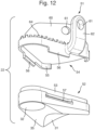
- the talar portion 22 has a first region 31 on a lower surface of the talar portion 22 (see Figure 12 for example).
- the talar portion 22 has a second region 32 on the lower surface of the talar portion 22.
- the calcaneal portion 24 has a first region 41 on an upper surface of the calcaneal portion 24 (see Figure 10 for example).
- the first region 41 of the talar portion lower surface is thus a third region.
- the calcaneal portion 24 has a second region 42 on the upper surface of the calcaneal portion 24.
- the second region 42 of the calcaneal portion upper surface is thus a fourth region.
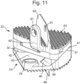
- the first region 31 of the talar portion 22 is configured to be in contact with the first region 41 of the calcaneal portion 24 during use, as shown for example in Figure 11 .
- the second region 32 of the talar portion 22 is configured to be in contact with the second region 42 of the calcaneal portion 24 during use, as shown for example in Figure 11 .
- the first region 31 of the talar portion 22 is not in contact with any portion of the second region 42 of the calcaneal portion 24 in use.
- the second region 32 of the talar portion 22 is not in contact with any portion of the first region 41 of the calcaneal portion 24 in use.
- first and second regions 31,32,41,42 may be configured such that, throughout the allowed range of relative movement between the talar portion 22 and the calcaneal portion 24, there is always a continuous separating region 35 on the lower surface of the talar portion 22 that separates the first region 31 from the second region 32 throughout the allowed range of relative movement.
- the separating region 35 may be such that at no time throughout the allowed range of relative movement is the separating region 35 in contact with any part of the calcaneal portion 24.
- first and second regions 31,32,41,42 may be configured such that, throughout the allowed range of relative movement between the talar portion 22 and the calcaneal portion 24, there is always a continuous separating region 45 on the upper surface of the calcaneal portion 24 that separates the first region 41 from the second region 42 throughout the allowed range of relative movement.
- the separating region 45 may be such that at no time throughout the allowed range of relative movement is the separating region 45 in contact with any part of the talar portion 22.
- the first regions 31 and 41 are shaped so as to allow sliding of the first region 31 of the lower surface of the talar portion 22 over the first region 41 of the upper surface of the calcaneal portion 24.
- the second regions 32 and 42 are shaped so as to define a pivot point and to constrain the sliding of the first region 31 of the lower surface of the talar portion 22 over the first region 41 of the upper surface of the calcaneal portion 24 to trajectories that involve pivoting of the talar portion 22 relative to the calcaneal portion 24 about the pivot point.
- the second regions 32 and 42 may be shaped so as to define a line (curved or straight) of pivot points and to constrain the sliding of the first region 31 of the lower surface of the talar portion 22 over the first region 41 of the upper surface of the calcaneal portion 24 to trajectories that involve pivoting of the talar portion 22 relative to the calcaneal portion 24 about one of a plurality of pivot points lying along the line of pivot points.
- the sliding of the first regions 31 and 41 relative to each other is along a curved trajectory.
- one of the first region 31 and the first region 41 comprises a concave component and the other of the first region 31 and the first region 41 (the third region) comprises a convex component.
- the curved trajectory is provided by means of cooperation between the concave curved shape of the first region 31 (as shown for example in Figure 12 ) and the convex curved shape of the first region 41 (as shown for example in Figure 10 ).
- the sliding along a curved trajectory may imitate a sliding along a curved trajectory that occurs between the posterior facet 1 of the calcaneum 104 and the posterior facet 5 of the talus 102.
- the combination of the first regions 31 and 41 may therefore be seen as providing functionality that is the same or similar to the functionality that is provided by the combination of the posterior facets 1 and 5 of the calcaneum 104 and talus 102.
- the first surfaces 31 and 41 are configured such that the sliding of the first regions 31 and 41 relative to each other constitutes rotation of the talar portion 22 relative to the calcaneal portion 24 about an axis that is fixed during a portion or all of an allowed range of sliding. This rotation imitates rotation that is provided by the combination of the posterior facets 1 and 5 of the calcaneum 104 and talus 102 in the natural subtalar joint.
- the axis of rotation 34 passes through the pivot point 36 (or, in other embodiments, through the line of pivot points, where a line of pivot points is provided).
- the axis of rotation 34 may pass through a region adjacent to the pivot point that overlaps with one or both of the second regions 32 and 42.
- the axis of rotation 24 may pass through a region adjacent to the line of pivot points, where a line of pivot points is provided, the region overlapping with one or both of the second regions 32 and 42.
- one of the first regions 31 and 41 of the lower and upper surfaces comprises a portion of an external surface of a frustum.
- the other of the first regions of the lower and upper surfaces may comprise a portion of an internal surface of a frustum, optionally the same frustum.
- the first region 31 of the lower surface of the talar portion 22 comprises a portion of the internal surface of a frustum (i.e. is concave).
- the first region 41 of the upper surface of the calcaneal portion 24 comprises a portion of the external surface of a frustum (i.e. is convex).
- the geometries may be reversed, with the first region 31 of the lower surface of the talar portion 22 having a convex form (e.g. a portion of an external surface of a frustum) and the first region 41 of the upper surface of the calcaneal portion 24 having a concave form (e.g. a portion of an internal surface of a frustum).
- a convex form e.g. a portion of an external surface of a frustum
- the first region 41 of the upper surface of the calcaneal portion 24 having a concave form (e.g. a portion of an internal surface of a frustum).
- one of the second regions 32 and 42 comprises a ball-like protrusion and the other of the second regions 42 and 32 comprises a cup-like depression.
- the resulting arrangement may be referred to as a ball and socket joint.
- a ball-like protrusion is generally rounded and could for example comprise a portion that forms part of an approximate sphere.
- a cup-like depression is generally rounded and could for example comprise a portion that forms part of an approximate sphere.
- Figures 10 and 12 show an embodiment in which the second region 32 of the talar portion 22 comprises a cup-like depression and the second region 42 of the calcaneal portion 24 comprises a ball-like protrusion.
- the geometries may be reversed, with the second region 32 of the lower surface of the talar portion 22 having a ball-like protrusion and the second region 42 of the upper surface of the calcaneal portion 24 having a cup-like depression.
- one of the second regions comprises a ball-like protrusion and the other of the second regions comprises a channel with a rounded base.
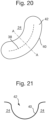
- An example of a channel 40 with a rounded base is shown in Figure 20 .
- Such a channel 40 could be formed in the talar portion 22 instead of the cup-like depression in the example shown in Figure 12 .
- Such a channel 40 could cooperate with a second region 42 comprising a ball-like protrusion such as that shown in the example of Figure 10 .
- the cooperation between such a channel 40 and a ball-like protrusion could allow pivoting of the talar portion 22 about the calcaneal portion 24 about one or more pivot points along a line 38 of pivot points.
- the talar portion 22 comprises an upper component 51 and a lower component 52.
- the upper component 51 is configured to be rigidly attached to the talus 102.
- the lower component 51 presents the lower surface of the talar portion 22.
- the lower component 52 is formed from a material having a lower coefficient of friction than the upper component 51.
- the upper component 51 may be formed from a metal and the lower component 52 may be formed from a plastic or a ceramic material or another type of material that has the required lower coefficient of friction than the metal.
- the upper surface of the calcaneal portion 24 may be formed from a metal.
- Figure 12 shows an example configuration of the upper and lower components 51 and 52.
- the lower component 52 is provided with a recessed region 53 that is configured to fit within a space 54 provided on a lower portion of the upper component 51.
- a rim 55 engages against the laterally outer borders of the recessed region 53 and provides lateral stability to the connection.
- An engaging tongue 56 is provided for engaging with a corresponding groove 57 to connect the upper and lower components 51 and 52 together, for example in the manner of a snap-fitting connection.
- the calcaneal portion 24 may comprise a lower component configured to be rigidly attached to the calcaneum 104 and an upper component that presents the upper surface of the calcaneal portion 24, the upper component being formed from a material having a lower coefficient of friction than the lower component.
- the lower component may be formed from a metal and the upper component may be formed from a plastic or a ceramic material or another type of material that has the required lower coefficient of friction than the metal.
- the lower surface of the talar portion 22 may be formed from a metal.
- the combination of the materials of the upper surface of the calcaneal portion 24 and the lower surface of the talar portion 22, at least in the first and second regions 31,32,41,42 where the upper and lower surfaces are in contact with each other, should be such as to provide 1) an appropriate level of friction in both the loaded and unloaded states, and 2) appropriate longevity (e.g. suitably low wearing rate).
- the level of friction may be arranged to be similar to the level of friction encountered between the corresponding facets of the talus 102 and calcaneum 104 in the natural subtalar joint.
- the materials and shapes of the first regions 31 and 41 are configured such that the sliding of the first regions 31 and 41 relative to each other is substantially prevented by friction between the first regions 31 and 41 when 10% or more of the patient's weight is applied between the talar and calcaneal portions 22 and 24.
- friction may be arranged to be such that sliding is very difficult or impossible for an average patient to effect while applying the 10% or more of the patient's weight.
- the talar portion 22 or the calcaneal portion 24 comprises one or more abutment members 46 configured to restrict the sliding of the first regions 31 and 41 relative to each other to within a predetermined range.
- the sliding of the first regions 31 and 41 relative to each other constitutes rotation of the talar portion 22 relative to the calcaneal portion 24, the one or more abutment members 46 may be configured to restrict the rotation to a range of 40 degrees or less.
- the calcaneal portion 24 comprises at least one of the abutment members 46 and the talar portion 22 is configured to be brought into contact with one of the abutment members 46 of the calcaneal portion 24 at one or both extreme ends of the predetermined range of sliding of the first regions 31 and 41 relative to each other.
- the talar portion 22 were to be slid in an anticlockwise sense (for the particular device shown in Figure 11 and as viewed in Figure 11 ) a portion 48 of the lower surface of the talar portion 22 would eventually be brought into abutment against the abutment member 46.
- a corresponding abutment member 46 is provided on the other side of the first region 41 and will limit a range of possible rotation in the opposite sense by abutment of a corresponding portion 48 of the lower surface of the talar portion 22 with the corresponding abutment member 46.
- the provision of such abutment members 46 limits the range of rotation that is allowed, in a similar manner to the way that movement is limited in the natural subtalar joint. The risk of injury to surrounding anatomy by excessive movement is therefore reduced.
- the talar portion 22 may comprises at least one of the abutment members 46 and the calcaneal portion 24 may be configured to be brought into contact with one of the abutment members 46 of the talar portion 22 at one or both extreme ends of the predetermined range of sliding of the first regions 31 and 41 relative to each other.
- the talar portion 22 and the calcaneal portion 24 are configured to be implanted in such a way that, when viewed from above, the first regions 31 and 41 overlap with a region where the posterior facet of the subtalar joint (e.g. the posterior facet 1 of the calcaneum 104, the posterior facet 5 of the talus 102, or both) was located prior to implantation of the implant 20.
- the posterior facet of the subtalar joint e.g. the posterior facet 1 of the calcaneum 104, the posterior facet 5 of the talus 102, or both
- the talar portion 22 and the calcaneal portion 24 are configured to be implanted in such a way that, when viewed from above, the second regions 32 and 42 overlap with a region where the middle facet of the subtalar joint (e.g. the middle facet 2 of the calcaneum 204, the middle facet 6 of the talus 102, or both) was located prior to implantation of the implant 20.
- the second regions 32 and 42 overlap with a central point of the middle facet.
- an implant 20 according to an embodiment is provided.
- the implant 20 may be one of the examples discussed above or any other embodiment falling within the scope of the claims.
- a space is prepared between the talus 102 and the calcaneum 104 that is suitable for accommodating the implant 20.
- the space may be prepared by cutting a region out of the bone in either or both of the talus 102 and the calcaneum 104.
- the implant 20 is implanted in the space in such a way that, when viewed from above, the first regions 31 and 41 overlap with a region where the posterior facet of the subtalar joint (e.g. the posterior facet 1 of the calcaneum 104, the posterior facet 5 of the talus 102, or both) was located prior to implantation of the implant 20 and the second regions 32 and 42 overlap with a region where the middle facet of the subtalar joint (e.g. the middle facet 2 of the calcaneum 204, the middle facet 6 of the talus 102, or both) was located prior to implantation of the implant 20.
- the posterior facet of the subtalar joint e.g. the posterior facet 1 of the calcaneum 104, the posterior facet 5 of the talus 102, or both
- the middle facet of the subtalar joint e.g. the middle facet 2 of the calcaneum 204, the middle facet 6 of the talus 102, or
- a probe may be used to identify a central point of either or both of the middle facets 2 and 6. The identified central point is then used as a reference to make the bony cuts. Once the surfaces are cut a trial implant may be placed in situ and then the hindfoot will be moved from side to side (inversion/eversion) a few times to allow the implant to settle to the best fit position. The trial implant or an associated jig may then be pinned and used as a reference to position the relevant portion of the final implant 20 (i.e. the part of the talar portion 22 that is to be fixed to the bone or the part of the calcaneal portion 24 that is to be fixed to the bone).
- fixation features may be provided on the talar portion 22 and on the calcaneal portion 24 to allow the portions 22 and 24 to be fixed rigidly and reliability to the bones of the talus 102 and calcaneum 104.
- the talar portion 22 may be provided with a rigid fin 60 and a side arm 62 (in the particular example shown, where the talar portion is formed from an upper component 51 and a lower component 52, these features are provided in the upper component 51).
- the rigid fin 60 may narrow in a direction of insertion (upwards in the Figures), to facilitate insertion.
- the rigid fin 60 may also comprise a fixation hole 61 to allow traversal of the rigid fin 60 by a fixing member such as a screw, bolt or pin.
- the rigid fin 60 has an elongate cross-section when viewed from above, thereby providing stability to the implant.
- the side arm 62 also comprises a fixation hole 61 to allow traversal of the side arm 62 by a fixing member such as a screw, bolt or pin.
- the talar portion 22 further comprises a surface structure comprising a plurality of protrusions 64 extending upwards. In the implanted state, the protrusions 64 extend into the bone and help to prevent slippage occurring between the talar portion 22 and the talus 102.
- the calcaneal portion 24 may also comprise a rigid fin 66 on the surface that is to engage against the bone of the calcaneum 24 (the lower surface of the calcaneal portion 24).
- the rigid fin 66 may comprise a fixation hole 61 (or, in the example shown, a fixation cut-out 67) to allow traversal of the rigid fin 66 by a fixing member 70 such as a screw, bolt or pin (a screw 70 engaging in a threaded hole 72 in the example shown).
- the rigid fin 66 has an elongate cross-section when viewed from above, thereby providing stability to the implant 20 in the implanted state.
- the calcaneal portion 24 may further comprise a surface structure comprising a plurality of protrusions 74 extending downwards. In the implanted state, the protrusions 74 extend into the bone and help to prevent slippage occurring between the calcaneal portion 24 and the calcaneum 104.
- the calcaneal portion 24 comprises a further fixation hole 76 configured to allow traversal of the calcaneal portion by a fixing member such as a screw, bolt of pin, for fixing the calcaneal portion to the calcaneum 104.
Landscapes
- Health & Medical Sciences (AREA)
- Orthopedic Medicine & Surgery (AREA)
- Cardiology (AREA)
- Oral & Maxillofacial Surgery (AREA)
- Transplantation (AREA)
- Engineering & Computer Science (AREA)
- Biomedical Technology (AREA)
- Heart & Thoracic Surgery (AREA)
- Vascular Medicine (AREA)
- Life Sciences & Earth Sciences (AREA)
- Animal Behavior & Ethology (AREA)
- General Health & Medical Sciences (AREA)
- Public Health (AREA)
- Veterinary Medicine (AREA)
- Prostheses (AREA)
Description
- The present invention relates to a subtalar joint implant for replacing a natural subtalar joint existing between the talus and calcaneum bones of a patient. The present invention is directed in particular to a subtalar joint implant that is reliable and provides realistic emulation of the functions of a healthy natural subtalar joint.
- Arthritis is a common chronic condition as people become older, and with an ageing population the healthcare costs associated with osteoarthritis will continue to rise. Joint replacement is a successful treatment for hip, knee, shoulder and ankle arthritis allowing restoration of function for patients. Such joint replacements are able to provide realistic emulation of the functions of the non-damaged joints.
- End-Stage ankle and hindfoot arthritis is a major problem that has been shown to affect quality of life as much as end stage heart disease.. At the time of writing it is estimated that up to 70,000 people are affected by subtalar joint arthritis in the UK alone. The commonest cause is posttraumatic, occurring in up to 16.9% of patients following a calcaneal fracture. Other non-traumatic causes include longstanding flat foot, tendon dysfunction and inflammatory arthritis. Aside from the use of painkillers, activity modification, and injections of steroids, there is only a single operative treatment at present - removal of the subtalar joints and fusion of the talus to the calcaneum (subtalar joint fusion). Fusion causes transmission of stresses to adj acent joints that might later fail. Although subtalar joint replacement has been attempted, it has not been successful, with early failure rates in the series of the first 100 of greater than 50% (Fournol S, Medical Chirurgie Pied 15: 67-71, 1999).
- The creation of a subtalar joint replacement that is as functionally effective and reliable as the widely used hip and knee replacements is inhibited by the higher complexity of the subtalar joint and the lack of a consensus on a detailed understanding of the mechanics of the joint. The ankle complex comprises a number of bones articulating by joints between them. It is commonly thought that the majority of up and down movements (doriflexion/plantarflexion) take place at the true ankle joint, between the tibia and talus, whereas side to side balancing movements (inversion/eversion) are thought to take place at the subtalar joint, which is the joint between the talus and calcaneum (heel bone). However, it has proved difficult to construct a mechanical arrangement that emulates the function of the subtalar joint in a reliable and realistic manner.
-
CN201001789 andWO 2013/025194 A1 discloses examples of arrangements in which talar and calcaneal components of a subtalar joint prosthesis are configured to be slidable relative to each other in order to emulate function provided by a natural subtalar joint. The realism of the emulation is limited, however, because the sliding is not constrained in the same way as the movement allowed by the natural subtalar joint especially under load. Excessive and/or unnatural movement may lead to clinical instability and early failure of the prosthesis. Another previous design of subtalar joint prosthesis is given inUS 2014/039506 A1 . - It is an object of the invention to provide a subtalar joint implant that provides a more reliable and realistic emulation of the functions of a healthy natural subtalar joint.
- According to an aspect of the invention, there is provided a subtalar joint implant according to claim 1.
- The combination of the relative sliding motion between the first regions and the constraining action of the pivot point or line of pivot points defined by the second regions provides a realistic emulation of the movement allowed by the natural subtalar joint in a non-loaded situation (e.g. as the foot is placed on an uneven surface and adapts to the shape of the floor).
- Further, the inventors have realised that the poor performance of previous subtalar implants resulted from inadequate understanding of subtalar joint motion in the natural joint. The inventors have realised in particular that under tibiotalar vertical loading, the natural subtalar joint complex is in a close-packed position with maximum talar head surface contact in the acetabulum pedis. The component ligaments of the latter are under maximum tension and the posterior talocalcaneal surfaces are interlocked. The inventors have recognised that in this position (e.g. single leg mid stance) the subatalar joint has minimal motion and the majority of motion (inversion and eversion) takes place at the ankle joint (between the tibia and talus) or at the mid and forefoot.. In contrast in a non-loaded situation (e.g. during heel strike), the majority of the inversion and eversion takes place at the subtalar j oint, by rotation of the posterior facet about an axis passing through the middle facet (and constrained to pivot about the middle facet), allowing the foot to be positioned on an uneven surface prior to mid-stance. Experiments performed by the inventors assessing the motion of the hindfoot complex in human subjects in a loaded and unloaded situation revealed a significant reduction in total side-to-side motion (inversion/eversion) between loaded and unloaded situations.
- The combination of the relative sliding motion between the first regions and the constraining action of the pivot point or line of pivot points defined by the second regions when unloaded emulates the movement of the natural joint. Under load the curved shapes of the first and second regions provides a large surface area of contact and friction which increases the stability of the construct reducing motion compared to the non loaded state, and hence stability of the construct, a further emulation of the natural joint.
- In an embodiment the sliding of the first regions relative to each other is along a curved trajectory. The curved trajectory desirably emulates the curved trajectory followed by the relative movement between the talus and the calcaneum (particularly the posterior facets of the talus and calcaneus) in the natural subtalar joint. In an embodiment, the sliding of the first regions relative to each other constitutes rotation of the talar portion relative to the calcaneal portion about an axis that is fixed during at least a portion of an allowed range of sliding. This movement provides a good approximation of an important aspect of the movement found in the natural subtalar joint. In an embodiment, when viewed from above, said axis passes through said pivot point or pivot points or a region adjacent to the pivot point or pivot points that overlaps with one or both of the second regions. This movement enhances further the emulation of the movement found in the natural subtalar joint. Furthermore, the movements described above are realisable in an efficient and reliable manner using readily manufactured cooperating (e.g. complimentary) shapes. In an embodiment the movement is realised using cooperating frustums for the first regions and a ball and socket arrangement for the second regions.
- In an embodiment, the materials and shapes of the first regions are configured such that the sliding of the first regions relative to each other is substantially prevented by friction between the first regions when 10% or more of the patient's weight is applied between the talar and calcaneal portions, optionally 20% or more, optionally 30% or more, optionally 40% or more, optionally 50% or more. Thus, the subtalar joint implant enters a locked state in which very little or no movement is possible between the talar and calcaneal portions, thus emulating the stability that is also present in the loaded state in the natural joint.
- In an embodiment, the talar portion or the calcaneal portion comprises one or more abutment members configured to restrict the sliding of the first regions relative to each other to within a predetermined range. This further enhances the stability of the implant, both in the loaded and non-loaded states. The abutment regions restrict relative movement of the talar and calcaneal portions to be within a predetermined range. The predetermined range may for example correspond to the range of movement allowed by a typical natural subtalar j oint. The restriction of movement by means of abutment members reliably prevents excessive relative movement between the talar portion and the calcaneal portion, which could be lead to clinical instability, which means that the subject feels unstable, and could fall over, leading to excessive stresses and potential injury. In addition, this excessive motion could lead to abnormal forces on the implants leading to implant-bone interface failure.
- In an embodiment, the sliding of the first regions relative to each other constitutes rotation of the talar portion relative to the calcaneal portion and the one or more abutment members are configured to restrict the rotation to a range of 40 degrees or less, optionally 38 degrees or less, optionally 36 degrees or less, optionally 34 degrees or less, optionally 32 degrees or less, optionally 30 degrees or less, optionally 28 degrees or less, optionally 26 degrees or less, optionally 24 degrees or less, optionally 22 degrees or less, optionally 20 degrees or less. This type and range of movement closely corresponds to movement allowed by a typical natural subtalar joint.
- In an embodiment, the talar and calcaneal portions are configured to be implanted in such a way that, when viewed from above, the first regions overlap with a region where the posterior facet of the subtalar joint was located prior to implantation of the implant. This arrangement provides particularly accurate emulation of the function of the natural joint because the first surfaces, which provide a sliding movement between the talus and calcaneum that is similar to that provided by the movement of the talus over the posterior facet of the subtalar joint, are located in the same or a similar position to the posterior facet.
- In an embodiment, the talar and calcaneal portions are configured to be implanted in such a way that, when viewed from above, the second regions overlap with a region where the middle facet (and preferably where a central point of the middle facet) of the subtalar joint was located prior to implantation of the implant. This arrangement provides particularly accurate emulation of the function of the natural joint because the second surfaces, which constrain the sliding movement between the talus and calcaneum in a similar manner to the middle facet of the subtalar joint (namely such that the sliding occurs as a pivoting about a pivot point or line of pivot points) are located in the same or a similar position to the middle facet (and/or central point thereof). The arrangement is particularly effective when combined with the requirement for the first regions to overlap with a region where the posterior facet of the subtalar joint was located prior to implantation of the implant. This combination ensures that the orientation of the first surfaces (e.g. the axes of the frustums of the first surfaces when they are shaped as frustums) are aligned in a similar direction (e.g. an oblique orientation from posterolateral to anteromedial) to the surfaces of the posterior facet of the subtalar j oint. This orientation helps to ensure that inversion and eversion can occur through a similar trajectory to that achieved by a healthy, natural subtalar joint.
- Also disclosed is a method of implanting a subtalar joint implant for replacing a natural subtalar joint existing between the talus and calcaneum bones of a patient, wherein the implant comprises: a talar portion configured to be rigidly attached to the talus; and a calcaneal portion configured to be rigidly attached to the calcaneum, wherein, where upper and lower directions are defined relative to the orientation of the implant when implanted in a weight bearing or standing patient: a first and a second region of a lower surface of the talar portion are configured to be in contact with respective first and second regions of an upper surface of the calcaneal portion during use; the first regions of the lower and upper surfaces are shaped so as to allow sliding of the first region of the lower surface over the first region of the upper surface; and the second regions of the lower and upper surfaces are shaped so as to define a pivot point or line or pivot points and constrain said sliding of the first region of the lower surface over the first region of the upper surface to trajectories that involve pivoting of the talar portion relative to the calcaneal portion about the pivot point or pivot points, wherein the method comprises: preparing a space between the talus and calcaneum that is suitable for accommodating the implant; implanting the implant in the space in such a way that, when viewed from above, the first regions overlap with a region where the posterior facet of the subtalar joint was located prior to implantation of the implant and the second regions overlap with a region where the middle facet (and preferably where a central point of the middle facet) of the subtalar joint was located prior to implantation of the implant.
- Implanting the implant in this way provides particularly accurate emulation of the function of the natural joint because the first surfaces, which provide a sliding movement between the talus and calcaneum that is similar to that provided by the movement of the talus over the posterior facet of the subtalar joint are located in the same or a similar position to the posterior facet, and the second surfaces, which constrain the sliding movement between the talus and calcaneum in a similar manner to the middle facet of the subtalar joint (namely to occur as a pivoting about a pivot point or line of pivot points) are located in the same or a similar position to the middle facet. The orientation of the first surfaces (e.g. the axes of the frustums of the first surfaces when they are shaped as frustums) are made to be aligned in a similar direction (e.g. an oblique orientation from posterolateral to anteromedial) to the surfaces of the posterior facet of the subtalar joint. This orientation helps to ensure that inversion and eversion can occur through a similar trajectory to that achieved by a healthy, natural subtalar joint.
- Embodiments of the invention will now be described, by way of example only, with reference to the accompanying schematic drawings in which corresponding reference symbols indicate corresponding parts, and in which:
-
Figure 1 is an anatomical top view of a foot, showing the calcaneum and navicular bone; -
Figure 2 is a side view from one side of the structure shown inFigure 1 ; -
Figure 3 is a side view from the other side of the structure shown inFigure 1 ; -
Figure 4 is an anatomical bottom view of the talus; -
Figure 5 corresponds to the view ofFigure 1 with a calcaneal portion of a subtalar implant attached to the calcaneum; -
Figure 6 is a side view from one side of the structure shown inFigure 5 ; -
Figure 7 is a side view from the other side of the structure shown inFigure 5 ; -
Figure 8 is an anatomical bottom view of the talus with a talar portion of a subtalar implant attached to the talus; -
Figure 9 depicts a perspective exploded view of upper and lower components of a talar portion of an example subtalar implant; -
Figure 10 depicts a perspective view of a calcaneal portion of the example subtalar implant ofFigure 9 ; -
Figure 11 depicts the talar and calcaneal portions ofFigures 9 and 10 assembled together to form the subtalar implant as it will be configured in the implanted state; -
Figure 12 depicts an alternative perspective exploded view of the upper and lower components of the talar portion shown inFigure 9 , showing undersides of the upper and lower components; -
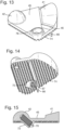
Figure 13 depicts a perspective view from above of a calcaneal portion of an example subtalar implant; -
Figure 14 depicts a perspective view from below of the calcaneal portion ofFigure 13 ; -
Figure 15 depicts a side sectional view through a central region of the calcaneal portion shown inFigures 13 and 14 ; -
Figure 16 is a top view of an example calcaneal portion in the implanted state, illustrating a representative axis about which rotation of the talar portion can occur and a representative pivot point about which pivoting of the talar portion can occur; -
Figure 17 is a bottom view of an example talar portion compatible with the calcaneal portion ofFigure 16 , illustrating the axis of rotation and pivot point shown inFigure 16 ; -
Figure 18 depicts an arrangement that is the same as that shown inFigure 16 except that the axis of rotation does not pass exactly through the pivot point; -
Figure 19 is a bottom view of an example talar portion compatible with the calcaneal portion ofFigure 18 , illustrating the axis of rotation and pivot point shown inFigure 18 ; -
Figure 20 is a schematic top view of a second region comprising a channel with a rounded base, the channel allowing pivoting of a talar portion about a calcaneal portion about one or more of a plurality of different pivot points on a line of pivot points; and -
Figure 21 is a schematic side sectional view along line A-A inFigure 20 . -
Figures 1-4 illustrate an example subtalar joint.Figure 1 is a view, along the distal direction, of the calcaneum (heel bone) 104 and thenavicular bone 106.Figures 2 and 3 are respective side views of the structures shown inFigure 1. Figure 4 is a view, along the proximal direction, of thetalus 102. The subtalar joint is the articulation between thetalus 102 and thecalcaneum 104 below the ankle joint. The subtalar joint is considered to be a plane synovial joint, also commonly referred to as a condyloid joint, between thetalus 102 above, thecalcaneum 104 below and thenavicular bone 106 in front. The subtalar joint is composed of three articulation surfaces between thetalus 102 and the calcaneum 104: the posterior facet (surfaces 1 and 5), the middle facet (surfaces 2 and 6) and the anterior facet (surfaces 3 and 4). The anterior and middle facets in some patients are touching and almost form one joint, in others (most) the two joints are separate with a small gap in between them. - The
talus 102 acts as the load bearing fulcrum between the ankle and subtalar joint. Its dome articulates with the ankle, its head with the navicular and its under surface with thecalcaneum 104 forming the subtalar joint. It is 60% covered in cartilage and gives rise to no muscle origin. It has a main blood supply running from anterior to posterior derived from the dorsalis pedis artery, medial deltoid and tarsal canal arteries. - The
calcaneum 104 is a cancellous bone that forms the bony heel with its large posterior tuberosity. The load bearing posterior third of the bone is extra-articular and also acts a lever arm for its attachment of the gastrosoleus complex. When viewed from behind in plantigrade stance, the heel sits in 10-15 degrees of valgus with respect to the coronal axis of the leg. This alignment changes during gait. The middle third of the calcaneum is lined dorsally with hyaline articular cartilage and comprises the posterior facet of the subtalar joint. The posterior facet surface has a complex oblique orientation from posterolateral to anteromedial. When viewed along the oblique orientation axis, the calcaneum portion 1 of the posterior facet surface is convex. Perpendicular to this view the calcaneum portion 1 of the posterior facet surface is down-sloping and again convex posteriorly to anterior. This shape is reflected in thetalar portion 5 of the posterior facet with which the posterior facet 1 of thecalcaneum 104 engages, thereby forming a congruent subtalar joint. - The anterior third of the
calcaneum 104 comprises theanterior 2 and middle 3 facets of the subtalar joint and the sustentaculum tali. These smaller facets are concave in an arc that is completed by the articular surface of the navicular approximating the socket of the "coxa pedis" in which sits the ball shaped talar head. The overlyinganterior talus 102 is congruent with thecalcaneum 104. - Short and stout interosseus talocalcaneal ligaments provide stability to the subtalar joint. They are most prominent in the sinus tarsi directly under the weight-bearing axis of the leg. In addition to providing stability, they provide a semi-controlled axis of motion for the joint and in this role they are sometimes regarded as analogous to the cruciates of the knee. Laterally and posteriorly are two thinner talocalcaneal ligaments which also play a supporting role. Kite's angle is the talocalcaneal angle in the frontal plane and represents the divergence of the respective longitudinal axes. Stance phase value of 17-21 degrees is considered normal. On the lateral image the calcaneal pitch is normally 20-25 degrees from the horizontal with a talar pitch very similar. The overall lateral talocalcaneal angle is a combined value at 30-50 degrees.
- The medial talocalcaneal ligament extends from the medial tubercle of the
talus 102 to the sustentaculum tali on the medial surface of thecalcaneum 104. A synovial membrane lines the capsule of the joint, and the joint is wrapped in a capsule of short fibers that are continuous with the talocalconeonavicular and calcaneocuboid joints of the foot. - The subtalar joint and the ankle form a link between the long bones of the leg and the perpendicular construct of the foot. Movements of the ankle require reactionary changes in the subtalar and transverse tarsal joints for effective load transmission and propulsion. Movements of the subtalar joint are complex and differ with closed or open chain stages of gait. They accommodate irregularities in ground contact by unlocking the hind and midfoot during heel strike to stance phase. Subsequently the talar movements about the
calcaneum 104 andnavicular 106 draw the heel into varus and help supinate the foot, which creates a more rigid construct to allow propulsive power to be transmitted. - The changing talocalcaneal relationship plays a role in stabilising the ankle complex. The importance of this can sometimes be seen when the natural condition is disrupted by subtalar or triple fusion operations. After such operations the ankle can be subjected to coronal forces of varus and valgus that were previously absorbed in the hindfoot. This in turn can cause eventual talar tilt and accelerated wear with uneven joint space loss.
- The inventors have recognised that the natural subtalar joint allows inversion and eversion of the foot via an internal and external motion of the
talus 102 over the curved surface of the posterior facet 1 of thecalcaneum 104 about a pivot point defined by themiddle facet 2. The inventors have further recognised that the normal inversion and eversion of the subtalar joint (which is actually rotation) takes place mainly during non load bearing stance. In single legged midstance, the joint locks and minimal motion occurs. In the following description, embodiments of a subtalar joint implant 20 are disclosed that allow the natural function of the subtalar joint to be emulated in a realistic and reliable manner, based on the above understanding and using components that can be manufactured easily and in a commercially viable way. -
Figures 5-8 illustrate the subtalar joint ofFigures 1-4 with elements of a subtalar joint implant 20 according to an embodiment attached to thecalcaneum 104 andtalus 102.Figures 9-15 show the implant 20 in further detail. - The implant 20 is configured to replace the natural subtalar joint existing between the
talus 102 andcalcaneum 104 bones of a patient. The implant 20 comprises atalar portion 22. Thetalar portion 22 is configured to be rigidly attached to thetalus 102. The implant 20 further comprises acalcaneal portion 24. Thecalcaneal portion 24 is configured to be rigidly attached to thecalcaneum 104. In the following discussion the upper and lower directions are defined relative to the orientation of the implant 20 when implanted in a weight bearing (e.g. standing) patient. - The
talar portion 22 has afirst region 31 on a lower surface of the talar portion 22 (seeFigure 12 for example). Thetalar portion 22 has asecond region 32 on the lower surface of thetalar portion 22. Thecalcaneal portion 24 has afirst region 41 on an upper surface of the calcaneal portion 24 (seeFigure 10 for example). Thefirst region 41 of the talar portion lower surface is thus a third region. Thecalcaneal portion 24 has asecond region 42 on the upper surface of thecalcaneal portion 24. Thesecond region 42 of the calcaneal portion upper surface is thus a fourth region. Thefirst region 31 of thetalar portion 22 is configured to be in contact with thefirst region 41 of thecalcaneal portion 24 during use, as shown for example inFigure 11 . Thesecond region 32 of thetalar portion 22 is configured to be in contact with thesecond region 42 of thecalcaneal portion 24 during use, as shown for example inFigure 11 . - Optionally, the
first region 31 of thetalar portion 22 is not in contact with any portion of thesecond region 42 of thecalcaneal portion 24 in use. Optionally, thesecond region 32 of thetalar portion 22 is not in contact with any portion of thefirst region 41 of thecalcaneal portion 24 in use. - For example, the first and
second regions talar portion 22 and thecalcaneal portion 24, there is always acontinuous separating region 35 on the lower surface of thetalar portion 22 that separates thefirst region 31 from thesecond region 32 throughout the allowed range of relative movement. The separatingregion 35 may be such that at no time throughout the allowed range of relative movement is the separatingregion 35 in contact with any part of thecalcaneal portion 24. - For example, the first and
second regions talar portion 22 and thecalcaneal portion 24, there is always acontinuous separating region 45 on the upper surface of thecalcaneal portion 24 that separates thefirst region 41 from thesecond region 42 throughout the allowed range of relative movement. The separatingregion 45 may be such that at no time throughout the allowed range of relative movement is the separatingregion 45 in contact with any part of thetalar portion 22. - The
first regions first region 31 of the lower surface of thetalar portion 22 over thefirst region 41 of the upper surface of thecalcaneal portion 24. - In the embodiment shown, the
second regions first region 31 of the lower surface of thetalar portion 22 over thefirst region 41 of the upper surface of thecalcaneal portion 24 to trajectories that involve pivoting of thetalar portion 22 relative to thecalcaneal portion 24 about the pivot point. In other embodiments, thesecond regions first region 31 of the lower surface of thetalar portion 22 over thefirst region 41 of the upper surface of thecalcaneal portion 24 to trajectories that involve pivoting of thetalar portion 22 relative to thecalcaneal portion 24 about one of a plurality of pivot points lying along the line of pivot points. - In an embodiment, the sliding of the
first regions - According to the invention, one of the
first region 31 and the first region 41 (the third region) comprises a concave component and the other of thefirst region 31 and the first region 41 (the third region) comprises a convex component. The curved trajectory is provided by means of cooperation between the concave curved shape of the first region 31 (as shown for example inFigure 12 ) and the convex curved shape of the first region 41 (as shown for example inFigure 10 ). The sliding along a curved trajectory may imitate a sliding along a curved trajectory that occurs between the posterior facet 1 of thecalcaneum 104 and theposterior facet 5 of thetalus 102. The combination of thefirst regions posterior facets 1 and 5 of thecalcaneum 104 andtalus 102. - In an embodiment, the
first surfaces first regions talar portion 22 relative to thecalcaneal portion 24 about an axis that is fixed during a portion or all of an allowed range of sliding. This rotation imitates rotation that is provided by the combination of theposterior facets 1 and 5 of thecalcaneum 104 andtalus 102 in the natural subtalar joint. - In an embodiment, as shown for example in
Figures 16 and 17 , when viewed from above, the axis ofrotation 34 passes through the pivot point 36 (or, in other embodiments, through the line of pivot points, where a line of pivot points is provided). Alternatively, as shown for example inFigure 18 and 19 , the axis ofrotation 34 may pass through a region adjacent to the pivot point that overlaps with one or both of thesecond regions rotation 24 may pass through a region adjacent to the line of pivot points, where a line of pivot points is provided, the region overlapping with one or both of thesecond regions - In an embodiment, one of the
first regions Figures 10 and12 , thefirst region 31 of the lower surface of thetalar portion 22 comprises a portion of the internal surface of a frustum (i.e. is concave). As shown inFigure 10 , for example, thefirst region 41 of the upper surface of thecalcaneal portion 24 comprises a portion of the external surface of a frustum (i.e. is convex). In other embodiments, the geometries may be reversed, with thefirst region 31 of the lower surface of thetalar portion 22 having a convex form (e.g. a portion of an external surface of a frustum) and thefirst region 41 of the upper surface of thecalcaneal portion 24 having a concave form (e.g. a portion of an internal surface of a frustum). - In an embodiment, one of the
second regions second regions Figures 10 and12 show an embodiment in which thesecond region 32 of thetalar portion 22 comprises a cup-like depression and thesecond region 42 of thecalcaneal portion 24 comprises a ball-like protrusion. In other embodiments, the geometries may be reversed, with thesecond region 32 of the lower surface of thetalar portion 22 having a ball-like protrusion and thesecond region 42 of the upper surface of thecalcaneal portion 24 having a cup-like depression. - In an alternative embodiment, one of the second regions comprises a ball-like protrusion and the other of the second regions comprises a channel with a rounded base. An example of a
channel 40 with a rounded base is shown inFigure 20 . Such achannel 40 could be formed in thetalar portion 22 instead of the cup-like depression in the example shown inFigure 12 . Such achannel 40 could cooperate with asecond region 42 comprising a ball-like protrusion such as that shown in the example ofFigure 10 . The cooperation between such achannel 40 and a ball-like protrusion could allow pivoting of thetalar portion 22 about thecalcaneal portion 24 about one or more pivot points along aline 38 of pivot points. - In an embodiment, the
talar portion 22 comprises anupper component 51 and alower component 52. Theupper component 51 is configured to be rigidly attached to thetalus 102. Thelower component 51 presents the lower surface of thetalar portion 22. Thelower component 52 is formed from a material having a lower coefficient of friction than theupper component 51. For example, theupper component 51 may be formed from a metal and thelower component 52 may be formed from a plastic or a ceramic material or another type of material that has the required lower coefficient of friction than the metal. In such an embodiment, the upper surface of thecalcaneal portion 24 may be formed from a metal.Figure 12 shows an example configuration of the upper andlower components lower component 52 is provided with a recessedregion 53 that is configured to fit within aspace 54 provided on a lower portion of theupper component 51. Arim 55 engages against the laterally outer borders of the recessedregion 53 and provides lateral stability to the connection. An engagingtongue 56 is provided for engaging with a correspondinggroove 57 to connect the upper andlower components - In other embodiments, the
calcaneal portion 24 may comprise a lower component configured to be rigidly attached to thecalcaneum 104 and an upper component that presents the upper surface of thecalcaneal portion 24, the upper component being formed from a material having a lower coefficient of friction than the lower component. For example, the lower component may be formed from a metal and the upper component may be formed from a plastic or a ceramic material or another type of material that has the required lower coefficient of friction than the metal. In such an embodiment, the lower surface of thetalar portion 22 may be formed from a metal. - The combination of the materials of the upper surface of the
calcaneal portion 24 and the lower surface of thetalar portion 22, at least in the first andsecond regions talus 102 andcalcaneum 104 in the natural subtalar joint. - In an embodiment, the materials and shapes of the
first regions first regions first regions calcaneal portions - In an embodiment, the
talar portion 22 or thecalcaneal portion 24 comprises one ormore abutment members 46 configured to restrict the sliding of thefirst regions first regions talar portion 22 relative to thecalcaneal portion 24, the one ormore abutment members 46 may be configured to restrict the rotation to a range of 40 degrees or less. - In an embodiment, as shown for example in
Figure 11 , thecalcaneal portion 24 comprises at least one of theabutment members 46 and thetalar portion 22 is configured to be brought into contact with one of theabutment members 46 of thecalcaneal portion 24 at one or both extreme ends of the predetermined range of sliding of thefirst regions Figure 11 , for example, it can be seen that if thetalar portion 22 were to be slid in an anticlockwise sense (for the particular device shown inFigure 11 and as viewed inFigure 11 ) aportion 48 of the lower surface of thetalar portion 22 would eventually be brought into abutment against theabutment member 46. The bringing into abutment of theportion 48 with theabutment member 46 would prevent any further rotation in the anticlockwise direction and therefore defines the range of possible rotation in the anticlockwise sense. Acorresponding abutment member 46 is provided on the other side of thefirst region 41 and will limit a range of possible rotation in the opposite sense by abutment of a correspondingportion 48 of the lower surface of thetalar portion 22 with thecorresponding abutment member 46. The provision ofsuch abutment members 46 limits the range of rotation that is allowed, in a similar manner to the way that movement is limited in the natural subtalar joint. The risk of injury to surrounding anatomy by excessive movement is therefore reduced. - In an alternative embodiment, the
talar portion 22 may comprises at least one of theabutment members 46 and thecalcaneal portion 24 may be configured to be brought into contact with one of theabutment members 46 of thetalar portion 22 at one or both extreme ends of the predetermined range of sliding of thefirst regions - In an embodiment, the
talar portion 22 and thecalcaneal portion 24 are configured to be implanted in such a way that, when viewed from above, thefirst regions calcaneum 104, theposterior facet 5 of thetalus 102, or both) was located prior to implantation of the implant 20. This can be seen to be the case in the embodiment shown inFigures 5-8 (compare for exampleFigure 5 withFigure 1 ). - In an embodiment, the
talar portion 22 and thecalcaneal portion 24 are configured to be implanted in such a way that, when viewed from above, thesecond regions middle facet 2 of the calcaneum 204, themiddle facet 6 of thetalus 102, or both) was located prior to implantation of the implant 20. Preferably, thesecond regions - An example methodology for implanting a subtalar joint implant 20 is described below.
- First, an implant 20 according to an embodiment is provided. The implant 20 may be one of the examples discussed above or any other embodiment falling within the scope of the claims.
- Secondly, a space is prepared between the
talus 102 and thecalcaneum 104 that is suitable for accommodating the implant 20. The space may be prepared by cutting a region out of the bone in either or both of thetalus 102 and thecalcaneum 104. - Thirdly, the implant 20 is implanted in the space in such a way that, when viewed from above, the
first regions calcaneum 104, theposterior facet 5 of thetalus 102, or both) was located prior to implantation of the implant 20 and thesecond regions middle facet 2 of the calcaneum 204, themiddle facet 6 of thetalus 102, or both) was located prior to implantation of the implant 20. - In an example method a probe may be used to identify a central point of either or both of the
middle facets talar portion 22 that is to be fixed to the bone or the part of thecalcaneal portion 24 that is to be fixed to the bone). - Various fixation features may be provided on the
talar portion 22 and on thecalcaneal portion 24 to allow theportions talus 102 andcalcaneum 104. - The following fixation features are provided in the example embodiment shown in
Figures 9-15 . - As shown in
Figure 9 , for example, thetalar portion 22 may be provided with arigid fin 60 and a side arm 62 (in the particular example shown, where the talar portion is formed from anupper component 51 and alower component 52, these features are provided in the upper component 51). Therigid fin 60 may narrow in a direction of insertion (upwards in the Figures), to facilitate insertion. Therigid fin 60 may also comprise afixation hole 61 to allow traversal of therigid fin 60 by a fixing member such as a screw, bolt or pin. Therigid fin 60 has an elongate cross-section when viewed from above, thereby providing stability to the implant. Theside arm 62 also comprises afixation hole 61 to allow traversal of theside arm 62 by a fixing member such as a screw, bolt or pin. Thetalar portion 22 further comprises a surface structure comprising a plurality ofprotrusions 64 extending upwards. In the implanted state, theprotrusions 64 extend into the bone and help to prevent slippage occurring between thetalar portion 22 and thetalus 102. - As shown in
Figures 13 and 14 , for example, thecalcaneal portion 24 may also comprise arigid fin 66 on the surface that is to engage against the bone of the calcaneum 24 (the lower surface of the calcaneal portion 24). Therigid fin 66 may comprise a fixation hole 61 (or, in the example shown, a fixation cut-out 67) to allow traversal of therigid fin 66 by a fixingmember 70 such as a screw, bolt or pin (ascrew 70 engaging in a threadedhole 72 in the example shown). Therigid fin 66 has an elongate cross-section when viewed from above, thereby providing stability to the implant 20 in the implanted state. Thecalcaneal portion 24 may further comprise a surface structure comprising a plurality ofprotrusions 74 extending downwards. In the implanted state, theprotrusions 74 extend into the bone and help to prevent slippage occurring between thecalcaneal portion 24 and thecalcaneum 104. In an embodiment, thecalcaneal portion 24 comprises afurther fixation hole 76 configured to allow traversal of the calcaneal portion by a fixing member such as a screw, bolt of pin, for fixing the calcaneal portion to thecalcaneum 104.
Claims (14)
- A subtalar joint implant (20), the implant comprising:a talar portion (22) having a lower surface, the lower surface comprising a first region (31) and a second region (32); anda calcaneal portion (24) comprising an upper surface having a third region (41) configured to contact the first region (31) of the talar portion (22) and a fourth region (42) configured to contact the second region (32) of the talar portion (22); andthe second region (32) and the fourth region (42) comprise at least one pivot point (36) defining a range of sliding motion of the talar portion (22) and calcaneal portion (24) of the implant (20);characterized in that:
one of the first region (31) and the third region (41) comprises a concave component and the other of the first region (31) and the third region (41) comprises a convex component. - The implant of claim 1, wherein the first region (31) is configured to slidably contact the third region (41) about the at least one pivot point (36).
- The implant of claim 1 or 2, wherein slidable contact between the first region (31) and the third region (41) is along a curved trajectory provided by means of cooperation between the concave component and the convex component.
- The implant of any preceding claim wherein the second region (32) and the fourth region (42) are centred about the at least one pivot point (36) and are configured to slidably contact one another.
- The implant of any preceding claim, wherein one of the second region (32) and the fourth region (42) comprises a ball-like protrusion and the other of the second region (32) and the fourth region (42) comprises a cup-like depression.
- The implant of any preceding claim, wherein the second region (32) and the fourth region (42) define the at least one pivot point (36) and constrain sliding of the first region (31) and the third region (41) about the at least one pivot point (36).
- The implant of claim 6, wherein the at least one pivot point (36) comprises a curved or straight line of pivot points (36).
- The implant of any preceding claim, wherein the calcaneal portion (24) comprises at least one abutment member (46) configured to restrict the sliding of the first region (31) relative to the third region (41) within a range.
- The implant of any preceding claim, wherein the talar portion (22) comprises an upper component (51) and a lower component (52).
- The implant of claim 9, wherein the lower component (52) of the talar portion (22) is formed from a material having a lower coefficient of friction than the upper component (51) of the talar portion (22).
- The implant of any preceding claim, wherein the calcaneal portion (24) comprises a lower component and an upper component, wherein the upper component is formed from a material having a lower coefficient of friction than the lower component.
- The implant of any preceding claim, wherein the talar portion (22) comprises a rigid fin (60) and a side arm (62) each further comprising a fixation hole (61) configured to accommodate a fixing member.
- The implant of any preceding claim, wherein the calcaneal portion 24 comprises a fixation hole (76) configured to accommodate a fixing member.
- The implant of any preceding claim, wherein the talar portion (22) comprises a first plurality of protrusions (64) and the calcaneal portion (24) comprises a second plurality of protrusions (74) configured to extend into bone and prevent slippage.
Applications Claiming Priority (3)
| Application Number | Priority Date | Filing Date | Title |
|---|---|---|---|
| GBGB1417618.4A GB201417618D0 (en) | 2014-10-06 | 2014-10-06 | Subtalar Joint Implant |
| PCT/GB2015/052634 WO2016055762A1 (en) | 2014-10-06 | 2015-09-11 | Subtalar joint implant |
| EP15770960.1A EP3203937B1 (en) | 2014-10-06 | 2015-09-11 | Subtalar joint implant |
Related Parent Applications (2)
| Application Number | Title | Priority Date | Filing Date |
|---|---|---|---|
| EP15770960.1A Division EP3203937B1 (en) | 2014-10-06 | 2015-09-11 | Subtalar joint implant |
| EP15770960.1A Division-Into EP3203937B1 (en) | 2014-10-06 | 2015-09-11 | Subtalar joint implant |
Publications (3)
| Publication Number | Publication Date |
|---|---|
| EP3756626A1 EP3756626A1 (en) | 2020-12-30 |
| EP3756626C0 EP3756626C0 (en) | 2024-07-31 |
| EP3756626B1 true EP3756626B1 (en) | 2024-07-31 |
Family
ID=51946895
Family Applications (2)
| Application Number | Title | Priority Date | Filing Date |
|---|---|---|---|
| EP15770960.1A Active EP3203937B1 (en) | 2014-10-06 | 2015-09-11 | Subtalar joint implant |
| EP20176094.9A Active EP3756626B1 (en) | 2014-10-06 | 2015-09-11 | Subtalar joint implant |
Family Applications Before (1)
| Application Number | Title | Priority Date | Filing Date |
|---|---|---|---|
| EP15770960.1A Active EP3203937B1 (en) | 2014-10-06 | 2015-09-11 | Subtalar joint implant |
Country Status (6)
| Country | Link |
|---|---|
| US (1) | US10117749B2 (en) |
| EP (2) | EP3203937B1 (en) |
| DK (1) | DK3203937T3 (en) |
| ES (2) | ES2990138T3 (en) |
| GB (1) | GB201417618D0 (en) |
| WO (1) | WO2016055762A1 (en) |
Families Citing this family (8)
| Publication number | Priority date | Publication date | Assignee | Title |
|---|---|---|---|---|
| CN106691635B (en) * | 2016-12-30 | 2019-12-03 | 北京爱康宜诚医疗器材有限公司 | Calcaneal prosthesis |
| CN108210130B (en) * | 2018-01-08 | 2023-09-08 | 四川大学华西医院 | Talar prosthesis |
| EP3698761B1 (en) | 2019-02-22 | 2021-11-17 | Stryker European Operations Limited | Total ankle prosthesis |
| WO2022150402A1 (en) * | 2021-01-05 | 2022-07-14 | Best Step Orthopedics LLC | Talonavicular joint prosthesis and method of implanting the prosthesis |
| AU2022201151A1 (en) * | 2021-03-01 | 2022-09-15 | Paragon 28, Inc. | Methods for performing an arthroplasty of the subtalar joint |
| WO2022213085A1 (en) | 2021-03-30 | 2022-10-06 | Paragon 28, Inc, | Orthopedic implants and methods |
| JP2025502366A (en) * | 2022-01-18 | 2025-01-24 | パラゴン28・インコーポレイテッド | Systems, implants and methods for joint arthroplasty - Patents.com |
| US20230320861A1 (en) * | 2022-04-12 | 2023-10-12 | Paragon 28, Inc. | Surgical methods for procedures of the subtalar joint |
Citations (3)
| Publication number | Priority date | Publication date | Assignee | Title |
|---|---|---|---|---|
| EP1433444B1 (en) * | 2002-12-23 | 2005-11-16 | DePuy Products, Inc. | Mobile talar component for total ankle replacement implant |
| CN201001789Y (en) * | 2007-02-14 | 2008-01-09 | 桂鉴超 | Artificial prosthesis for subtalar joint replacement |
| CN103156711A (en) * | 2011-12-14 | 2013-06-19 | 西安瑞捷生物科技有限公司 | Artificial prosthesis |
Family Cites Families (5)
| Publication number | Priority date | Publication date | Assignee | Title |
|---|---|---|---|---|
| FR2669215B1 (en) * | 1990-11-15 | 1993-01-22 | Mecanique Const Distr Ste Gle | ASTRAGALO-CALCANEAN JOINT PROSTHESIS AND APPARATUS FOR ITS IMPLANTATION. |
| US9005301B2 (en) * | 2009-04-29 | 2015-04-14 | Foot Innovations, Llc | System and method for modifying talocalcaneal relationship in a foot |
| US9775717B2 (en) | 2011-08-15 | 2017-10-03 | Lew C. Schon | Subtalar joint prostheseis and its method of implantation |
| WO2014022665A1 (en) * | 2012-08-01 | 2014-02-06 | Innovative Biological Implant Solutions LLC | Subtalar joint prosthesis and installation device |
| US20140128985A1 (en) * | 2012-11-07 | 2014-05-08 | Roy W. Sanders | Joint Arthroplasty Systems, Methods, and Components |
-
2014
- 2014-10-06 GB GBGB1417618.4A patent/GB201417618D0/en not_active Ceased
-
2015
- 2015-09-11 US US15/517,090 patent/US10117749B2/en active Active
- 2015-09-11 ES ES20176094T patent/ES2990138T3/en active Active
- 2015-09-11 EP EP15770960.1A patent/EP3203937B1/en active Active
- 2015-09-11 EP EP20176094.9A patent/EP3756626B1/en active Active
- 2015-09-11 ES ES15770960T patent/ES2822051T3/en active Active
- 2015-09-11 DK DK15770960.1T patent/DK3203937T3/en active
- 2015-09-11 WO PCT/GB2015/052634 patent/WO2016055762A1/en not_active Ceased
Patent Citations (3)
| Publication number | Priority date | Publication date | Assignee | Title |
|---|---|---|---|---|
| EP1433444B1 (en) * | 2002-12-23 | 2005-11-16 | DePuy Products, Inc. | Mobile talar component for total ankle replacement implant |
| CN201001789Y (en) * | 2007-02-14 | 2008-01-09 | 桂鉴超 | Artificial prosthesis for subtalar joint replacement |
| CN103156711A (en) * | 2011-12-14 | 2013-06-19 | 西安瑞捷生物科技有限公司 | Artificial prosthesis |
Also Published As
| Publication number | Publication date |
|---|---|
| US20170246004A1 (en) | 2017-08-31 |
| US10117749B2 (en) | 2018-11-06 |
| DK3203937T3 (en) | 2020-08-17 |
| EP3756626A1 (en) | 2020-12-30 |
| EP3756626C0 (en) | 2024-07-31 |
| EP3203937A1 (en) | 2017-08-16 |
| ES2822051T3 (en) | 2021-04-28 |
| GB201417618D0 (en) | 2014-11-19 |
| ES2990138T3 (en) | 2024-11-28 |
| EP3203937B1 (en) | 2020-07-15 |
| WO2016055762A1 (en) | 2016-04-14 |
Similar Documents
| Publication | Publication Date | Title |
|---|---|---|
| EP3203937B1 (en) | Subtalar joint implant | |
| EP2635239B1 (en) | Prosthetic device with multi-axis dual bearing assembly | |
| JP5410027B2 (en) | Movable support assembly | |
| US6893467B1 (en) | Knee prosthesis | |
| US10398562B2 (en) | Talar implant for modifying joint kinematics | |
| JP4943655B2 (en) | High performance knee prosthesis | |
| Michael et al. | Biomechanics of the ankle joint and clinical outcomes of total ankle replacement | |
| CN101301231B (en) | Mobile bearing assembly having a non-planar interface | |
| CN101214175B (en) | Knee joint endoprosthesis | |
| CN101951859B (en) | Artificial knee joint including flection in bearing member | |
| US20150045902A1 (en) | Semi Constrained Polyaxial Endoprosthetic Ankle Joint Replacement Implant | |
| KR102018051B1 (en) | Tibia component of artificial ankle joint | |
| AU2010343075B2 (en) | Resurfacing implant | |
| US20190091032A1 (en) | Talar Ankle Implant | |
| KR102066837B1 (en) | Talar component of artificial ankle joint | |
| WO2020130986A1 (en) | Ankle prosthesis | |
| EP2719359A1 (en) | Prosthesis | |
| WO2009073924A1 (en) | Endoprosthesis for a metatarsophalangeal joint | |
| US11129720B2 (en) | Cruciate replacing artificial knee | |
| CN205849594U (en) | High matching degree bion knee-joint prosthesis | |
| EP3405144B1 (en) | Talar implant for modifying joint kinematics | |
| WO2023203382A1 (en) | Ankle prosthesis | |
| US20220241082A1 (en) | Ankle prosthesis | |
| KR102608868B1 (en) | Tibia Bearing component for a Knee Prosthesis With Reverse Slope | |
| Hintermann et al. | Biomechanical Considerations for Total Ankle Arthroplasty |
Legal Events
| Date | Code | Title | Description |
|---|---|---|---|
| PUAI | Public reference made under article 153(3) epc to a published international application that has entered the european phase |
Free format text: ORIGINAL CODE: 0009012 |
|
| STAA | Information on the status of an ep patent application or granted ep patent |
Free format text: STATUS: THE APPLICATION HAS BEEN PUBLISHED |
|
| AC | Divisional application: reference to earlier application |
Ref document number: 3203937 Country of ref document: EP Kind code of ref document: P |
|
| AK | Designated contracting states |
Kind code of ref document: A1 Designated state(s): AL AT BE BG CH CY CZ DE DK EE ES FI FR GB GR HR HU IE IS IT LI LT LU LV MC MK MT NL NO PL PT RO RS SE SI SK SM TR |
|
| STAA | Information on the status of an ep patent application or granted ep patent |
Free format text: STATUS: REQUEST FOR EXAMINATION WAS MADE |
|
| 17P | Request for examination filed |
Effective date: 20210629 |
|
| RBV | Designated contracting states (corrected) |
Designated state(s): AL AT BE BG CH CY CZ DE DK EE ES FI FR GB GR HR HU IE IS IT LI LT LU LV MC MK MT NL NO PL PT RO RS SE SI SK SM TR |
|
| GRAP | Despatch of communication of intention to grant a patent |
Free format text: ORIGINAL CODE: EPIDOSNIGR1 |
|
| STAA | Information on the status of an ep patent application or granted ep patent |
Free format text: STATUS: GRANT OF PATENT IS INTENDED |
|
| RIC1 | Information provided on ipc code assigned before grant |
Ipc: A61F 2/30 20060101ALN20240206BHEP Ipc: A61F 2/42 20060101AFI20240206BHEP |
|
| INTG | Intention to grant announced |
Effective date: 20240219 |
|
| GRAS | Grant fee paid |
Free format text: ORIGINAL CODE: EPIDOSNIGR3 |
|
| GRAA | (expected) grant |
Free format text: ORIGINAL CODE: 0009210 |
|
| STAA | Information on the status of an ep patent application or granted ep patent |
Free format text: STATUS: THE PATENT HAS BEEN GRANTED |
|
| AC | Divisional application: reference to earlier application |
Ref document number: 3203937 Country of ref document: EP Kind code of ref document: P |
|
| AK | Designated contracting states |
Kind code of ref document: B1 Designated state(s): AL AT BE BG CH CY CZ DE DK EE ES FI FR GB GR HR HU IE IS IT LI LT LU LV MC MK MT NL NO PL PT RO RS SE SI SK SM TR |
|
| REG | Reference to a national code |
Ref country code: CH Ref legal event code: EP Ref country code: GB Ref legal event code: FG4D |
|
| REG | Reference to a national code |
Ref country code: DE Ref legal event code: R096 Ref document number: 602015089427 Country of ref document: DE |
|
| REG | Reference to a national code |
Ref country code: IE Ref legal event code: FG4D |
|
| U01 | Request for unitary effect filed |
Effective date: 20240801 |
|
| U07 | Unitary effect registered |
Designated state(s): AT BE BG DE DK EE FI FR IT LT LU LV MT NL PT SE SI Effective date: 20240820 |
|
| U20 | Renewal fee for the european patent with unitary effect paid |
Year of fee payment: 10 Effective date: 20240919 |
|
| REG | Reference to a national code |
Ref country code: ES Ref legal event code: FG2A Ref document number: 2990138 Country of ref document: ES Kind code of ref document: T3 Effective date: 20241128 |
|
| PG25 | Lapsed in a contracting state [announced via postgrant information from national office to epo] |
Ref country code: NO Free format text: LAPSE BECAUSE OF FAILURE TO SUBMIT A TRANSLATION OF THE DESCRIPTION OR TO PAY THE FEE WITHIN THE PRESCRIBED TIME-LIMIT Effective date: 20241031 |
|
| PG25 | Lapsed in a contracting state [announced via postgrant information from national office to epo] |
Ref country code: PL Free format text: LAPSE BECAUSE OF FAILURE TO SUBMIT A TRANSLATION OF THE DESCRIPTION OR TO PAY THE FEE WITHIN THE PRESCRIBED TIME-LIMIT Effective date: 20240731 Ref country code: GR Free format text: LAPSE BECAUSE OF FAILURE TO SUBMIT A TRANSLATION OF THE DESCRIPTION OR TO PAY THE FEE WITHIN THE PRESCRIBED TIME-LIMIT Effective date: 20241101 |
|
| PG25 | Lapsed in a contracting state [announced via postgrant information from national office to epo] |
Ref country code: IS Free format text: LAPSE BECAUSE OF FAILURE TO SUBMIT A TRANSLATION OF THE DESCRIPTION OR TO PAY THE FEE WITHIN THE PRESCRIBED TIME-LIMIT Effective date: 20241130 |
|
| PG25 | Lapsed in a contracting state [announced via postgrant information from national office to epo] |
Ref country code: HR Free format text: LAPSE BECAUSE OF FAILURE TO SUBMIT A TRANSLATION OF THE DESCRIPTION OR TO PAY THE FEE WITHIN THE PRESCRIBED TIME-LIMIT Effective date: 20240731 |
|
| PG25 | Lapsed in a contracting state [announced via postgrant information from national office to epo] |
Ref country code: RS Free format text: LAPSE BECAUSE OF FAILURE TO SUBMIT A TRANSLATION OF THE DESCRIPTION OR TO PAY THE FEE WITHIN THE PRESCRIBED TIME-LIMIT Effective date: 20241031 |
|
| PG25 | Lapsed in a contracting state [announced via postgrant information from national office to epo] |
Ref country code: RS Free format text: LAPSE BECAUSE OF FAILURE TO SUBMIT A TRANSLATION OF THE DESCRIPTION OR TO PAY THE FEE WITHIN THE PRESCRIBED TIME-LIMIT Effective date: 20241031 Ref country code: PL Free format text: LAPSE BECAUSE OF FAILURE TO SUBMIT A TRANSLATION OF THE DESCRIPTION OR TO PAY THE FEE WITHIN THE PRESCRIBED TIME-LIMIT Effective date: 20240731 Ref country code: NO Free format text: LAPSE BECAUSE OF FAILURE TO SUBMIT A TRANSLATION OF THE DESCRIPTION OR TO PAY THE FEE WITHIN THE PRESCRIBED TIME-LIMIT Effective date: 20241031 Ref country code: IS Free format text: LAPSE BECAUSE OF FAILURE TO SUBMIT A TRANSLATION OF THE DESCRIPTION OR TO PAY THE FEE WITHIN THE PRESCRIBED TIME-LIMIT Effective date: 20241130 Ref country code: HR Free format text: LAPSE BECAUSE OF FAILURE TO SUBMIT A TRANSLATION OF THE DESCRIPTION OR TO PAY THE FEE WITHIN THE PRESCRIBED TIME-LIMIT Effective date: 20240731 Ref country code: GR Free format text: LAPSE BECAUSE OF FAILURE TO SUBMIT A TRANSLATION OF THE DESCRIPTION OR TO PAY THE FEE WITHIN THE PRESCRIBED TIME-LIMIT Effective date: 20241101 |
|
| PG25 | Lapsed in a contracting state [announced via postgrant information from national office to epo] |
Ref country code: SM Free format text: LAPSE BECAUSE OF FAILURE TO SUBMIT A TRANSLATION OF THE DESCRIPTION OR TO PAY THE FEE WITHIN THE PRESCRIBED TIME-LIMIT Effective date: 20240731 |
|
| PG25 | Lapsed in a contracting state [announced via postgrant information from national office to epo] |
Ref country code: MC Free format text: LAPSE BECAUSE OF FAILURE TO SUBMIT A TRANSLATION OF THE DESCRIPTION OR TO PAY THE FEE WITHIN THE PRESCRIBED TIME-LIMIT Effective date: 20240731 |
|
| PG25 | Lapsed in a contracting state [announced via postgrant information from national office to epo] |
Ref country code: CZ Free format text: LAPSE BECAUSE OF FAILURE TO SUBMIT A TRANSLATION OF THE DESCRIPTION OR TO PAY THE FEE WITHIN THE PRESCRIBED TIME-LIMIT Effective date: 20240731 |
|
| PG25 | Lapsed in a contracting state [announced via postgrant information from national office to epo] |
Ref country code: SK Free format text: LAPSE BECAUSE OF FAILURE TO SUBMIT A TRANSLATION OF THE DESCRIPTION OR TO PAY THE FEE WITHIN THE PRESCRIBED TIME-LIMIT Effective date: 20240731 |
|
| REG | Reference to a national code |
Ref country code: CH Ref legal event code: PL |
|
| PLBE | No opposition filed within time limit |
Free format text: ORIGINAL CODE: 0009261 |
|
| STAA | Information on the status of an ep patent application or granted ep patent |
Free format text: STATUS: NO OPPOSITION FILED WITHIN TIME LIMIT |
|
| 26N | No opposition filed |
Effective date: 20250501 |
|
| PG25 | Lapsed in a contracting state [announced via postgrant information from national office to epo] |
Ref country code: CH Free format text: LAPSE BECAUSE OF NON-PAYMENT OF DUE FEES Effective date: 20240930 |
|
| PG25 | Lapsed in a contracting state [announced via postgrant information from national office to epo] |
Ref country code: IE Free format text: LAPSE BECAUSE OF NON-PAYMENT OF DUE FEES Effective date: 20240911 |
|
| PGFP | Annual fee paid to national office [announced via postgrant information from national office to epo] |
Ref country code: GB Payment date: 20250923 Year of fee payment: 11 |
|
| U20 | Renewal fee for the european patent with unitary effect paid |
Year of fee payment: 11 Effective date: 20250912 |
|
| PG25 | Lapsed in a contracting state [announced via postgrant information from national office to epo] |
Ref country code: RO Free format text: LAPSE BECAUSE OF FAILURE TO SUBMIT A TRANSLATION OF THE DESCRIPTION OR TO PAY THE FEE WITHIN THE PRESCRIBED TIME-LIMIT Effective date: 20240731 |
|
| PG25 | Lapsed in a contracting state [announced via postgrant information from national office to epo] |
Ref country code: CY Free format text: LAPSE BECAUSE OF FAILURE TO SUBMIT A TRANSLATION OF THE DESCRIPTION OR TO PAY THE FEE WITHIN THE PRESCRIBED TIME-LIMIT; INVALID AB INITIO Effective date: 20150911 |
|
| PGFP | Annual fee paid to national office [announced via postgrant information from national office to epo] |
Ref country code: ES Payment date: 20251013 Year of fee payment: 11 |
|
| PG25 | Lapsed in a contracting state [announced via postgrant information from national office to epo] |
Ref country code: HU Free format text: LAPSE BECAUSE OF FAILURE TO SUBMIT A TRANSLATION OF THE DESCRIPTION OR TO PAY THE FEE WITHIN THE PRESCRIBED TIME-LIMIT; INVALID AB INITIO Effective date: 20150911 |