EP3756541A1 - Electrocardiogram measurement system comprising patch-type electrocardiogram measurement apparatus - Google Patents
Electrocardiogram measurement system comprising patch-type electrocardiogram measurement apparatus Download PDFInfo
- Publication number
- EP3756541A1 EP3756541A1 EP19758242.2A EP19758242A EP3756541A1 EP 3756541 A1 EP3756541 A1 EP 3756541A1 EP 19758242 A EP19758242 A EP 19758242A EP 3756541 A1 EP3756541 A1 EP 3756541A1
- Authority
- EP
- European Patent Office
- Prior art keywords
- electrocardiogram
- measurement apparatus
- ecg
- data
- electrocardiogram measurement
- Prior art date
- Legal status (The legal status is an assumption and is not a legal conclusion. Google has not performed a legal analysis and makes no representation as to the accuracy of the status listed.)
- Granted
Links
Images


Classifications
-
- A—HUMAN NECESSITIES
- A61—MEDICAL OR VETERINARY SCIENCE; HYGIENE
- A61B—DIAGNOSIS; SURGERY; IDENTIFICATION
- A61B5/00—Measuring for diagnostic purposes; Identification of persons
- A61B5/0002—Remote monitoring of patients using telemetry, e.g. transmission of vital signals via a communication network
- A61B5/0015—Remote monitoring of patients using telemetry, e.g. transmission of vital signals via a communication network characterised by features of the telemetry system
- A61B5/002—Monitoring the patient using a local or closed circuit, e.g. in a room or building
-
- A—HUMAN NECESSITIES
- A61—MEDICAL OR VETERINARY SCIENCE; HYGIENE
- A61B—DIAGNOSIS; SURGERY; IDENTIFICATION
- A61B5/00—Measuring for diagnostic purposes; Identification of persons
- A61B5/24—Detecting, measuring or recording bioelectric or biomagnetic signals of the body or parts thereof
- A61B5/316—Modalities, i.e. specific diagnostic methods
- A61B5/318—Heart-related electrical modalities, e.g. electrocardiography [ECG]
-
- A—HUMAN NECESSITIES
- A61—MEDICAL OR VETERINARY SCIENCE; HYGIENE
- A61B—DIAGNOSIS; SURGERY; IDENTIFICATION
- A61B5/00—Measuring for diagnostic purposes; Identification of persons
- A61B5/24—Detecting, measuring or recording bioelectric or biomagnetic signals of the body or parts thereof
- A61B5/316—Modalities, i.e. specific diagnostic methods
- A61B5/318—Heart-related electrical modalities, e.g. electrocardiography [ECG]
- A61B5/33—Heart-related electrical modalities, e.g. electrocardiography [ECG] specially adapted for cooperation with other devices
-
- A—HUMAN NECESSITIES
- A61—MEDICAL OR VETERINARY SCIENCE; HYGIENE
- A61B—DIAGNOSIS; SURGERY; IDENTIFICATION
- A61B5/00—Measuring for diagnostic purposes; Identification of persons
- A61B5/0002—Remote monitoring of patients using telemetry, e.g. transmission of vital signals via a communication network
- A61B5/0004—Remote monitoring of patients using telemetry, e.g. transmission of vital signals via a communication network characterised by the type of physiological signal transmitted
- A61B5/0006—ECG or EEG signals
-
- A—HUMAN NECESSITIES
- A61—MEDICAL OR VETERINARY SCIENCE; HYGIENE
- A61B—DIAGNOSIS; SURGERY; IDENTIFICATION
- A61B5/00—Measuring for diagnostic purposes; Identification of persons
- A61B5/0002—Remote monitoring of patients using telemetry, e.g. transmission of vital signals via a communication network
- A61B5/0015—Remote monitoring of patients using telemetry, e.g. transmission of vital signals via a communication network characterised by features of the telemetry system
- A61B5/0022—Monitoring a patient using a global network, e.g. telephone networks, internet
-
- A—HUMAN NECESSITIES
- A61—MEDICAL OR VETERINARY SCIENCE; HYGIENE
- A61B—DIAGNOSIS; SURGERY; IDENTIFICATION
- A61B5/00—Measuring for diagnostic purposes; Identification of persons
- A61B5/0002—Remote monitoring of patients using telemetry, e.g. transmission of vital signals via a communication network
- A61B5/0015—Remote monitoring of patients using telemetry, e.g. transmission of vital signals via a communication network characterised by features of the telemetry system
- A61B5/0024—Remote monitoring of patients using telemetry, e.g. transmission of vital signals via a communication network characterised by features of the telemetry system for multiple sensor units attached to the patient, e.g. using a body or personal area network
-
- A—HUMAN NECESSITIES
- A61—MEDICAL OR VETERINARY SCIENCE; HYGIENE
- A61B—DIAGNOSIS; SURGERY; IDENTIFICATION
- A61B5/00—Measuring for diagnostic purposes; Identification of persons
- A61B5/24—Detecting, measuring or recording bioelectric or biomagnetic signals of the body or parts thereof
- A61B5/30—Input circuits therefor
- A61B5/307—Input circuits therefor specially adapted for particular uses
- A61B5/308—Input circuits therefor specially adapted for particular uses for electrocardiography [ECG]
-
- A—HUMAN NECESSITIES
- A61—MEDICAL OR VETERINARY SCIENCE; HYGIENE
- A61B—DIAGNOSIS; SURGERY; IDENTIFICATION
- A61B5/00—Measuring for diagnostic purposes; Identification of persons
- A61B5/24—Detecting, measuring or recording bioelectric or biomagnetic signals of the body or parts thereof
- A61B5/316—Modalities, i.e. specific diagnostic methods
- A61B5/318—Heart-related electrical modalities, e.g. electrocardiography [ECG]
- A61B5/333—Recording apparatus specially adapted therefor
-
- A—HUMAN NECESSITIES
- A61—MEDICAL OR VETERINARY SCIENCE; HYGIENE
- A61B—DIAGNOSIS; SURGERY; IDENTIFICATION
- A61B5/00—Measuring for diagnostic purposes; Identification of persons
- A61B5/68—Arrangements of detecting, measuring or recording means, e.g. sensors, in relation to patient
- A61B5/6801—Arrangements of detecting, measuring or recording means, e.g. sensors, in relation to patient specially adapted to be attached to or worn on the body surface
- A61B5/683—Means for maintaining contact with the body
- A61B5/6832—Means for maintaining contact with the body using adhesives
- A61B5/6833—Adhesive patches
-
- A—HUMAN NECESSITIES
- A61—MEDICAL OR VETERINARY SCIENCE; HYGIENE
- A61B—DIAGNOSIS; SURGERY; IDENTIFICATION
- A61B5/00—Measuring for diagnostic purposes; Identification of persons
- A61B5/68—Arrangements of detecting, measuring or recording means, e.g. sensors, in relation to patient
- A61B5/6887—Arrangements of detecting, measuring or recording means, e.g. sensors, in relation to patient mounted on external non-worn devices, e.g. non-medical devices
- A61B5/6898—Portable consumer electronic devices, e.g. music players, telephones, tablet computers
-
- A—HUMAN NECESSITIES
- A61—MEDICAL OR VETERINARY SCIENCE; HYGIENE
- A61B—DIAGNOSIS; SURGERY; IDENTIFICATION
- A61B5/00—Measuring for diagnostic purposes; Identification of persons
- A61B5/74—Details of notification to user or communication with user or patient; User input means
- A61B5/746—Alarms related to a physiological condition, e.g. details of setting alarm thresholds or avoiding false alarms
Definitions
- the present disclosure relates to an electrocardiogram measurement system comprising a patch-type electrocardiogram measurement apparatus, and more particularly, to an electrocardiogram measurement system comprising a patch-type electrocardiogram measurement apparatus capable of being connected to an external device to store electrocardiogram data.
- Products related to storage of the electrocardiogram (ECG) data known to date are largely divided into products in which data is stored in an embedded memory in a patch-type measurement apparatus itself and products in which data is transmitted to a smartphone through Bluetooth Low Energy (BLE) communication and stored in a memory in the smartphone, while an ECG signal is output in real time onto the screen of the smartphone.
- ECG electrocardiogram
- a patch-type ECG measurement apparatus using an embedded memory it is necessary to secure a memory space, which is disadvantageous in that miniaturization of the patch-type ECG measurement apparatus and memory reuse are not allowed. Furthermore, a patch-type ECG measurement apparatus that stores data in the memory of the smartphone has a limitation in that the smartphone must always be carried and connected.
- an electrocardiogram (ECG) measurement system comprising a patch-type ECG measurement apparatus in which ECG data is to be stored. Accordingly, it is possible to miniaturize the patch-type ECG measurement apparatus, and is not necessary to always carry a smartphone.
- an electrocardiogram measurement system includes: a patch-type electrocardiogram measurement apparatus; a first device connected to the electrocardiogram measurement apparatus by means of a first communication method and configured to store the electrocardiogram data measured by the electrocardiogram measurement apparatus; and a second device connected to the electrocardiogram measurement apparatus by means of the first communication method and configured to store the electrocardiogram data measured by the electrocardiogram measurement apparatus.
- the electrocardiogram data measured by the electrocardiogram measurement apparatus may include measured time information.
- a first time period in which the first device stores the electrocardiogram data measured by the electrocardiogram measurement apparatus, and a second time period in which the second device stores the electrocardiogram data measured by the electrocardiogram measurement apparatus may be at least partially at different times.
- the first device may receive and store the electrocardiogram data stored in the second device that has been measured by the electrocardiogram measurement apparatus.
- the first device may combine the electrocardiogram data stored in the first device and the electrocardiogram data received from the second device using the measured time information included in each piece of the electrocardiogram data.
- the first device may combine and display the electrocardiogram data stored in the first device and the electrocardiogram data received from the second device using the measured time information included in each piece of the electrocardiogram data.
- the first device may be characterized by instructing the second device to release the connection from the electrocardiogram measurement apparatus when the first device is in a state of being able to be connected with the electrocardiogram apparatus.
- the first device may be characterized by instructing the second device to be connected with the electrocardiogram measurement apparatus.
- the electrocardiogram measurement apparatus may generate a warning signal.
- the first device when there is no external device that is able to receive the electrocardiogram data measured in the electrocardiogram measurement apparatus, the electrocardiogram measurement apparatus may generate a warning signal.
- the first device when the first device is unable to receive the electrocardiogram data measured in the electrocardiogram measurement apparatus, and the second device is also unable to receive the electrocardiogram data measured in the electrocardiogram measurement apparatus, the first device may generate a warning signal.
- ECG electrocardiogram
- ECG electrocardiogram
- FIG. 1 is a configuration diagram of an ECG measurement system 100 comprising a patch-type ECG measurement apparatus according to an embodiment of the present disclosure.
- the ECG measurement system 100 includes an ECG measurement apparatus 10, a first device 20, and a second device 30.
- FIG. 2 is a configuration diagram of the ECG measurement apparatus 10 according to an embodiment of the present disclosure.
- the ECG measurement apparatus 10 may be configured by including a plurality of electrodes E1, a channel connection unit 11, a data processing unit 12, a first processor 13, and a first communication unit 14.
- the ECG measurement apparatus 10 has the shape of a patch type, and is attached to a human body to be able to measure ECG data of one or more channels by means of the plurality of electrodes E1.
- the number of ECG measurement channels of the ECG measurement apparatus 10 is possibly extended by receiving the ECG measurement data of the one or more channels, which is measured by means of the external electrodes E2, through the channel connection unit 11.
- an input terminal form may be exemplified which enables the measurement data from the external electrodes E2 to be used as an input of the data processing unit 12.
- the ECG data measured by means of the electrodes E1 of the ECG measurement apparatus 10 itself or the external electrodes E2 is amplified by the data processing unit 12 and then converted into a digital signal.
- the data processing unit 12 preferably includes an amplifier and an analog-to-digital converter.
- the ECG data output from the data processing unit 12 is inserted with time information at which the ECG data has been measured by the first processor 12, namely, a time-stamp, and then transmitted to an external device by means of a first communication method through the first communication unit 14.
- the first communication method may be exemplified by a Bluetooth low energy (BLE) communication.
- the ECG measurement apparatus 10 may transmit the ECG data to the external device and receive data from the external device through the first communication unit 14.
- the description is provided only with the ECG data, but it is natural to include a necessary control signal together with the data.
- FIG. 3 is a configuration diagram of the first device 20 according to an embodiment of the present disclosure.
- the first device 20 may be configured by including a second memory 21, a second processor 22, a second communication unit 23, and a third communication unit 24.
- the first device 20 may be implemented using a mobile terminal, which can bea smartphone, a tablet PC, or the like.
- the second memory 21 may store the ECG data measured by the ECG measurement apparatus 10.
- the first device 20 is installed with an application program, and thus the second processor 22 may execute the application program.
- the application program is executed by the second processor 22, the ECG data stored in the second memory 21 may be processed to be displayed on a screen of the first device 20.
- the second communication unit 23 receives the ECG data from the ECG measurement apparatus 10 by means of the first communication method.
- the first communication method may be exemplified by the BLE communication.
- the ECG data received by the second communication unit 23 is stored in the second memory 21.
- the ECG data received from the ECG measurement apparatus 10 is characterized by being inserted with the time information at which the ECG data has been measured, namely, the time-stamp.
- the third communication unit 24 enables transmission and reception of data with the second device by means of a wireless or wired communication method other than the first communication method.
- the third communication unit (24) may use a WiFi communication as another example.
- the second device 30 and the first device 20 may be directly connected through a USB terminal of the first device 20 and then data is input from or output to the second device 30.
- the ECG data input from the second device 30 through the third communication unit 24 or a direct connection is stored in the second memory 21.
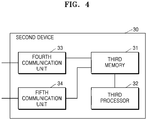
- FIG. 4 is a configuration diagram of the second device 30 according to an embodiment of the present disclosure.
- the second device 30 may be configured by including a third memory 31, a third processor 32, a fourth communication unit 33, and a fifth communication unit 34.
- the second device 30 is preferably implemented with a device miniaturized by mounting a communication function onto a dongle memory.
- the third memory 31 may store the ECG data measured by the ECG measurement apparatus 10.
- the third processor 32 may execute processing or the like for the ECG data.
- the fourth communication unit 33 receives the ECG data from the ECG measurement apparatus 10 by means of the first communication method.
- the first communication method may be exemplified by the BLE communication.
- the ECG data received by the fourth communication unit 33 is stored in the third memory 31.
- the ECG data received from the ECG measurement apparatus 10 is characterized by being inserted with the time information at which the ECG data has been measured, namely, the time-stamp.
- the fifth communication unit 34 enables transmission and reception of data with the first device 20 by means of a wireless communication method other than the first communication method.
- the fifth communication unit (34) may use a WiFi communication as an example.
- the second device 30 and the first device 20 may be directly connected through a USB terminal of the first device 20 and thus data transmission and reception with the second device 30 become possible.
- the first device 20 preferably operates as a master device that may transmit a command to the second device 30 to control the operation of the second device 30.
- the second device 30 is characterized by operating as a slave device. Accordingly, the first device 20 may not only receive connection status information about the second device 30 with another device, but also transmit a command for connecting the second device 30 with the other device or a command for releasing the connection of the second device 30 from the other device.
- the other device may be the ECG measurement apparatus 10.
- the ECG data measured by the ECG measurement apparatus 10 is stored in the first device 20.
- the second device 30 may be automatically connected to the ECG measurement apparatus 10 when the second device 30 is present around the ECG measurement apparatus 10. Accordingly, the ECG data measured by the ECG measurement apparatus 10 is stored in the second device 30.
- a time period in which the first device 20 stores the ECG data measured by the ECG measurement apparatus 10 and a time period in which the second device 30 stores the ECG data measured by the ECG measurement apparatus 10 are different from each other, and thus the time periods do not overlap.
- the time period in which the first device 20 stores the ECG data measured by the ECG measurement apparatus 10, and the time period in which the second device 30 stores the ECG data measured by the ECG measurement apparatus 10 are characterized by being at different times. This is caused by the characteristics of the BLE communication in which only one device may be connected to one communication module.
- the time period in which the first device 20 stores the ECG data measured by the ECG measurement apparatus 10 may be at least partially at different times.
- the first device 20 may receive and store the ECG data that has been measured by the ECG measurement apparatus 10 and stored in the second device 30.
- the first device 20 and the second device 20 may be exemplarily connected by means of a wireless communication method other than the first communication method, or a direct connection.
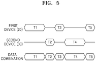
- FIG. 5 is an illustration of a combination of the ECG data in the first device 20.
- the ECG data is shown not overlapping, but it is natural that the ECG data stored in the first device 20 and the ECG data stored in the second device 20 at least partially overlap. This overlapping portion may be discerned by means of the time-stamp that is the characteristics of the present disclosure.
- the first device 20 combines the ECG data, which has been measured by the ECG measurement apparatus 10 and stored in the first device 20, and the ECG data, which has been measured by the ECG measurement apparatus 10 and stored in the second device 30, using the measured time information included in each piece of the ECG data, and then newly store the combined ECG data in the first device 20.
- the first device 20 when the second device 30 is connected and the ECG data is processed (displayed as an example) through an application program installed in the first device 20, the first device 20 is characterized by combining the ECG data, which has been measured by the ECG measurement apparatus 10 and stored in the first device 20, and the ECG data, which has been measured by the ECG measurement apparatus 10 and stored in the second device 30, using the measured time information included in each piece of the ECG data, and displaying the combined ECG data on the screen of the first device 20.
- the first device 20 may select one of the first device 20 or the second device 30 and allow the ECG data measured by the ECG measurement apparatus 10 to be stored therein.
- a method in which the first device 20 selects one of the first device 20 or the second device 30 will be described.
- the first device 20 instructs the second device 30 to release the connection from the ECG measurement apparatus 10. Accordingly, the connection between the second device 30 and the ECG measurement apparatus 10 is released, the first device 20 is connected with the ECG measurement apparatus 10, and thus the ECG data measured in the ECG measurement apparatus 10 is stored in the first device 20.
- the first device 20 may instruct the second device 30 to be connected with the ECG measurement apparatus 10.
- the first device 20 may release the connection of itself from the ECG measurement apparatus 10, and allow the second device 20 to be connected with the ECG measurement apparatus 10.
- the second device 30 may be automatically connected with the ECG measurement apparatus 10 when the second device 30 is present around the ECG measurement apparatus 10.
- the ECG measurement apparatus 10 When there is not any external device including the first device 20 or the second device 30 that may receive the ECG data measured by the ECG measurement apparatus 10, the ECG measurement apparatus 10 generates a warning signal to inform a user of a situation in which the ECG data is not possibly stored.
- the first device 20 when the first device 20 is not able to receive the ECG data measured by the ECG measurement apparatus 10, and the second device 20 is not also able to receive the ECG data measured by the ECG measurement apparatus 10, the first device 20 may generate a warning signal.
- the warning signal in the present disclosure may be generated by the ECG measurement apparatus 10 and/or the first device 20.
- any one of the first device 20 and the second device 30 may be selectively used as a device in which the ECG data is to be stored. Accordingly the patch-type ECG measurement apparatus 10 does not require a separate and embedded large-capacity memory, and thus may be miniaturized.
- the ECG measurement system 100 comprising the patch-type ECG measurement apparatus 10 of the present disclosure, it is not necessary to always carry the first device 20 of a large size like a smartphone, and the ECG data may be stored in the second device 30 of a small dongle type. Furthermore, according to the ECG measurement system 100 comprising the patch-type ECG measurement apparatus 10 of the present disclosure, pieces of the ECG data stored in different devices at different times are combined to one piece of data using the measured time information and thus the entire ECG data may be constructed, which increases the convenience of use.
Landscapes
- Health & Medical Sciences (AREA)
- Life Sciences & Earth Sciences (AREA)
- Engineering & Computer Science (AREA)
- Molecular Biology (AREA)
- Animal Behavior & Ethology (AREA)
- Pathology (AREA)
- Physics & Mathematics (AREA)
- Biomedical Technology (AREA)
- Heart & Thoracic Surgery (AREA)
- Medical Informatics (AREA)
- Veterinary Medicine (AREA)
- Surgery (AREA)
- Biophysics (AREA)
- General Health & Medical Sciences (AREA)
- Public Health (AREA)
- Cardiology (AREA)
- Computer Networks & Wireless Communication (AREA)
- Physiology (AREA)
- Multimedia (AREA)
- Measurement And Recording Of Electrical Phenomena And Electrical Characteristics Of The Living Body (AREA)
Abstract
Description
- The present disclosure relates to an electrocardiogram measurement system comprising a patch-type electrocardiogram measurement apparatus, and more particularly, to an electrocardiogram measurement system comprising a patch-type electrocardiogram measurement apparatus capable of being connected to an external device to store electrocardiogram data.
- Products related to storage of the electrocardiogram (ECG) data known to date are largely divided into products in which data is stored in an embedded memory in a patch-type measurement apparatus itself and products in which data is transmitted to a smartphone through Bluetooth Low Energy (BLE) communication and stored in a memory in the smartphone, while an ECG signal is output in real time onto the screen of the smartphone.
- For a patch-type ECG measurement apparatus using an embedded memory, it is necessary to secure a memory space, which is disadvantageous in that miniaturization of the patch-type ECG measurement apparatus and memory reuse are not allowed. Furthermore, a patch-type ECG measurement apparatus that stores data in the memory of the smartphone has a limitation in that the smartphone must always be carried and connected.
- In the prior art, exemplified is an electrode patch for ECG measurement and an ECG measurement device using same disclosed in Korean Application Publication No.
10-2012-0084950 (published on July 31, 2012 - Provided is an electrocardiogram (ECG) measurement system comprising a patch-type ECG measurement apparatus in which ECG data is to be stored. Accordingly, it is possible to miniaturize the patch-type ECG measurement apparatus, and is not necessary to always carry a smartphone.
- According to an aspect of the present disclosure, an electrocardiogram measurement system includes: a patch-type electrocardiogram measurement apparatus; a first device connected to the electrocardiogram measurement apparatus by means of a first communication method and configured to store the electrocardiogram data measured by the electrocardiogram measurement apparatus; and a second device connected to the electrocardiogram measurement apparatus by means of the first communication method and configured to store the electrocardiogram data measured by the electrocardiogram measurement apparatus.
- Furthermore, the electrocardiogram data measured by the electrocardiogram measurement apparatus may include measured time information. A first time period in which the first device stores the electrocardiogram data measured by the electrocardiogram measurement apparatus, and a second time period in which the second device stores the electrocardiogram data measured by the electrocardiogram measurement apparatus may be at least partially at different times.
- Specifically, the first device may receive and store the electrocardiogram data stored in the second device that has been measured by the electrocardiogram measurement apparatus. the first device may combine the electrocardiogram data stored in the first device and the electrocardiogram data received from the second device using the measured time information included in each piece of the electrocardiogram data.
- In addition, when the second device is connected and the first device displays the electrocardiogram data through an application program installed in the first device, the first device may combine and display the electrocardiogram data stored in the first device and the electrocardiogram data received from the second device using the measured time information included in each piece of the electrocardiogram data.
- Furthermore, in a state where the second device is connected with the electrocardiogram measurement apparatus by means of the first communication method, the first device may be characterized by instructing the second device to release the connection from the electrocardiogram measurement apparatus when the first device is in a state of being able to be connected with the electrocardiogram apparatus.
- In a state where the second device is able to be connected with the electrocardiogram measurement apparatus by means of the first communication method, the first device may be characterized by instructing the second device to be connected with the electrocardiogram measurement apparatus.
- In addition, when there is no external device that is able to receive the electrocardiogram data measured in the electrocardiogram measurement apparatus, the electrocardiogram measurement apparatus may generate a warning signal. Furthermore, when the first device is unable to receive the electrocardiogram data measured in the electrocardiogram measurement apparatus, and the second device is also unable to receive the electrocardiogram data measured in the electrocardiogram measurement apparatus, the first device may generate a warning signal.
- According to the electrocardiogram (ECG) measurement system comprising the patch-type ECG measurement apparatus of the present disclosure, a device in which ECG data is to be stored may be selectively used, and thus, it is possible to miniaturize the patch-type ECG measurement apparatus and is not necessary to always carry the smartphone and keep in connection.
-
-
FIG. 1 is a configuration diagram of an electrocardiogram (ECG) measurement system comprising a patch-type ECG measurement apparatus according to an embodiment of the present disclosure; -
FIG. 2 is a configuration diagram of an ECG measurement apparatus according to an embodiment of the present disclosure; -
FIG. 3 is a configuration diagram of a first device according to an embodiment of the present disclosure; -
FIG. 4 is a configuration diagram of a second device according to an embodiment of the present disclosure; and -
FIG. 5 is an illustration of a combination of ECG data in the first device. - Hereinafter, an electrocardiogram (ECG) measurement system comprising a patch-type ECG measurement apparatus according to an embodiment of the present disclosure will be described in detail with reference to the accompanying drawings.
- The following embodiments of the present disclosure are intended to embody the present disclosure, but not to limit or restrict the scope of the present disclosure. From the detailed description and embodiments of the present disclosure, all techniques easily conceivable by those skilled in the art to which the present disclosure pertains can be easily interpreted as belonging to the scope of the present disclosure.
- First,
FIG. 1 is a configuration diagram of anECG measurement system 100 comprising a patch-type ECG measurement apparatus according to an embodiment of the present disclosure. - As may be known from
FIG. 1 , theECG measurement system 100 according to the embodiment of the present disclosure includes anECG measurement apparatus 10, afirst device 20, and asecond device 30. -
FIG. 2 is a configuration diagram of theECG measurement apparatus 10 according to an embodiment of the present disclosure. - As may be known from
FIG. 2 , theECG measurement apparatus 10 may be configured by including a plurality of electrodes E1, achannel connection unit 11, adata processing unit 12, afirst processor 13, and afirst communication unit 14. - The
ECG measurement apparatus 10 has the shape of a patch type, and is attached to a human body to be able to measure ECG data of one or more channels by means of the plurality of electrodes E1. In addition, the number of ECG measurement channels of theECG measurement apparatus 10 is possibly extended by receiving the ECG measurement data of the one or more channels, which is measured by means of the external electrodes E2, through thechannel connection unit 11. As thechannel connection unit 11, an input terminal form may be exemplified which enables the measurement data from the external electrodes E2 to be used as an input of thedata processing unit 12. - The ECG data measured by means of the electrodes E1 of the
ECG measurement apparatus 10 itself or the external electrodes E2 is amplified by thedata processing unit 12 and then converted into a digital signal. To this end, thedata processing unit 12 preferably includes an amplifier and an analog-to-digital converter. - Furthermore, the ECG data output from the
data processing unit 12 is inserted with time information at which the ECG data has been measured by thefirst processor 12, namely, a time-stamp, and then transmitted to an external device by means of a first communication method through thefirst communication unit 14. Specifically, the first communication method may be exemplified by a Bluetooth low energy (BLE) communication. TheECG measurement apparatus 10 may transmit the ECG data to the external device and receive data from the external device through thefirst communication unit 14. Here, for convenience, the description is provided only with the ECG data, but it is natural to include a necessary control signal together with the data. -
FIG. 3 is a configuration diagram of thefirst device 20 according to an embodiment of the present disclosure. - As may be known from
FIG. 3 , thefirst device 20 may be configured by including asecond memory 21, asecond processor 22, asecond communication unit 23, and athird communication unit 24. As an example, thefirst device 20 may be implemented using a mobile terminal, which can bea smartphone, a tablet PC, or the like. - The
second memory 21 may store the ECG data measured by the ECG measurement apparatus 10.Thefirst device 20 is installed with an application program, and thus thesecond processor 22 may execute the application program. When the application program is executed by thesecond processor 22, the ECG data stored in thesecond memory 21 may be processed to be displayed on a screen of thefirst device 20. - The
second communication unit 23 receives the ECG data from theECG measurement apparatus 10 by means of the first communication method. The first communication method may be exemplified by the BLE communication. The ECG data received by thesecond communication unit 23 is stored in thesecond memory 21. The ECG data received from theECG measurement apparatus 10 is characterized by being inserted with the time information at which the ECG data has been measured, namely, the time-stamp. - The
third communication unit 24 enables transmission and reception of data with the second device by means of a wireless or wired communication method other than the first communication method. The third communication unit (24) may use a WiFi communication as another example. Naturally, thesecond device 30 and thefirst device 20 may be directly connected through a USB terminal of thefirst device 20 and then data is input from or output to thesecond device 30. The ECG data input from thesecond device 30 through thethird communication unit 24 or a direct connection is stored in thesecond memory 21. -
FIG. 4 is a configuration diagram of thesecond device 30 according to an embodiment of the present disclosure. - As may be known from
FIG. 4 , thesecond device 30 may be configured by including athird memory 31, athird processor 32, afourth communication unit 33, and afifth communication unit 34. As an example, thesecond device 30 is preferably implemented with a device miniaturized by mounting a communication function onto a dongle memory. - The
third memory 31 may store the ECG data measured by theECG measurement apparatus 10. Thethird processor 32 may execute processing or the like for the ECG data. - The
fourth communication unit 33 receives the ECG data from theECG measurement apparatus 10 by means of the first communication method. The first communication method may be exemplified by the BLE communication. The ECG data received by thefourth communication unit 33 is stored in thethird memory 31. The ECG data received from theECG measurement apparatus 10 is characterized by being inserted with the time information at which the ECG data has been measured, namely, the time-stamp. - The
fifth communication unit 34 enables transmission and reception of data with thefirst device 20 by means of a wireless communication method other than the first communication method. The fifth communication unit (34) may use a WiFi communication as an example. Naturally, thesecond device 30 and thefirst device 20 may be directly connected through a USB terminal of thefirst device 20 and thus data transmission and reception with thesecond device 30 become possible. - Hereinafter, a detailed description will be provided about a method for storing the ECG data, which has been measured by the
ECG measurement apparatus 10, in thefirst device 20 and thesecond device 30. - The
first device 20 preferably operates as a master device that may transmit a command to thesecond device 30 to control the operation of thesecond device 30. In other words, thesecond device 30 is characterized by operating as a slave device. Accordingly, thefirst device 20 may not only receive connection status information about thesecond device 30 with another device, but also transmit a command for connecting thesecond device 30 with the other device or a command for releasing the connection of thesecond device 30 from the other device. Here, the other device may be theECG measurement apparatus 10. - When the
first device 20 is connected to theECG measurement apparatus 10 by means of the first communication method, the ECG data measured by theECG measurement apparatus 10 is stored in thefirst device 20. - In addition, when the connection of the
first device 20 with theECG measurement apparatus 10 through the first communication method is released, thesecond device 30 may be automatically connected to theECG measurement apparatus 10 when thesecond device 30 is present around theECG measurement apparatus 10. Accordingly, the ECG data measured by theECG measurement apparatus 10 is stored in thesecond device 30. - In other words, a time period in which the
first device 20 stores the ECG data measured by theECG measurement apparatus 10, and a time period in which thesecond device 30 stores the ECG data measured by theECG measurement apparatus 10 are different from each other, and thus the time periods do not overlap. In other words, the time period in which thefirst device 20 stores the ECG data measured by theECG measurement apparatus 10, and the time period in which thesecond device 30 stores the ECG data measured by theECG measurement apparatus 10 are characterized by being at different times. This is caused by the characteristics of the BLE communication in which only one device may be connected to one communication module. Furthermore, even when a communication in which many devices are connected at the same time is used, namely, even when thefirst device 20 and thesecond device 30 simultaneously store the ECG data, overlapping ECG data may be discerned by means of the time information, namely, the time-stamp. To sum up, the time period in which thefirst device 20 stores the ECG data measured by theECG measurement apparatus 10, and the time period in which thesecond device 30 stores the ECG data measured by theECG measurement apparatus 10 may be at least partially at different times. - The
first device 20 may receive and store the ECG data that has been measured by theECG measurement apparatus 10 and stored in thesecond device 30. Thefirst device 20 and thesecond device 20 may be exemplarily connected by means of a wireless communication method other than the first communication method, or a direct connection. -
FIG. 5 is an illustration of a combination of the ECG data in thefirst device 20. Here, for convenience of explanation, the ECG data is shown not overlapping, but it is natural that the ECG data stored in thefirst device 20 and the ECG data stored in thesecond device 20 at least partially overlap. This overlapping portion may be discerned by means of the time-stamp that is the characteristics of the present disclosure. - The
first device 20 combines the ECG data, which has been measured by theECG measurement apparatus 10 and stored in thefirst device 20, and the ECG data, which has been measured by theECG measurement apparatus 10 and stored in thesecond device 30, using the measured time information included in each piece of the ECG data, and then newly store the combined ECG data in thefirst device 20. - In detail, when the
second device 30 is connected and the ECG data is processed (displayed as an example) through an application program installed in thefirst device 20, thefirst device 20 is characterized by combining the ECG data, which has been measured by theECG measurement apparatus 10 and stored in thefirst device 20, and the ECG data, which has been measured by theECG measurement apparatus 10 and stored in thesecond device 30, using the measured time information included in each piece of the ECG data, and displaying the combined ECG data on the screen of thefirst device 20. - The
first device 20 may select one of thefirst device 20 or thesecond device 30 and allow the ECG data measured by theECG measurement apparatus 10 to be stored therein. Hereinafter, a method in which thefirst device 20 selects one of thefirst device 20 or thesecond device 30 will be described. - In a state where the
second device 30 is connected with theECG measurement apparatus 10 by means of the first communication method, when thefirst device 20 is in a state of being able to be connected to theECG measurement apparatus 10 by means of the first communication method, thefirst device 20 instructs thesecond device 30 to release the connection from theECG measurement apparatus 10. Accordingly, the connection between thesecond device 30 and theECG measurement apparatus 10 is released, thefirst device 20 is connected with theECG measurement apparatus 10, and thus the ECG data measured in theECG measurement apparatus 10 is stored in thefirst device 20. - In addition, when the
second device 30 is in a state of being able to be connected to theECG measurement apparatus 10 by means of the first communication method, thefirst device 20 may instruct thesecond device 30 to be connected with theECG measurement apparatus 10. As an example, in a state where thefirst device 20 is connected with theECG measurement apparatus 10 by means of the first communication method, when thefirst device 20 intends to stop the storage of the ECG data, thefirst device 20 may release the connection of itself from theECG measurement apparatus 10, and allow thesecond device 20 to be connected with theECG measurement apparatus 10. However, when thefirst device 20 releases the connection of itself with theECG measurement apparatus 10, thesecond device 30 may be automatically connected with theECG measurement apparatus 10 when thesecond device 30 is present around theECG measurement apparatus 10. - When there is not any external device including the
first device 20 or thesecond device 30 that may receive the ECG data measured by theECG measurement apparatus 10, theECG measurement apparatus 10 generates a warning signal to inform a user of a situation in which the ECG data is not possibly stored. - Furthermore, when the
first device 20 is not able to receive the ECG data measured by theECG measurement apparatus 10, and thesecond device 20 is not also able to receive the ECG data measured by theECG measurement apparatus 10, thefirst device 20 may generate a warning signal. - In other words, the warning signal in the present disclosure may be generated by the
ECG measurement apparatus 10 and/or thefirst device 20. - As the foregoing, according to the
ECG measurement system 100 comprising a patch-typeECG measurement apparatus 10 of the present disclosure, any one of thefirst device 20 and thesecond device 30 may be selectively used as a device in which the ECG data is to be stored. Accordingly the patch-typeECG measurement apparatus 10 does not require a separate and embedded large-capacity memory, and thus may be miniaturized. - In addition, according to the
ECG measurement system 100 comprising the patch-typeECG measurement apparatus 10 of the present disclosure, it is not necessary to always carry thefirst device 20 of a large size like a smartphone, and the ECG data may be stored in thesecond device 30 of a small dongle type. Furthermore, according to theECG measurement system 100 comprising the patch-typeECG measurement apparatus 10 of the present disclosure, pieces of the ECG data stored in different devices at different times are combined to one piece of data using the measured time information and thus the entire ECG data may be constructed, which increases the convenience of use.
Claims (8)
- An electrocardiogram measurement system comprising: a patch-type electrocardiogram measurement apparatus, wherein electrocardiogram data measured by the electrocardiogram measurement apparatus comprises measured time information.
- The electrocardiogram measurement system of claim 1, further comprising: a first device connected to the electrocardiogram measurement apparatus by means of a first communication method and configured to store the electrocardiogram data measured by the electrocardiogram measurement apparatus; and a second device connected to the electrocardiogram measurement apparatus by means of the first communication method and configured to store the electrocardiogram data measured by the electrocardiogram measurement apparatus, wherein a time period in which the first device stores the electrocardiogram data measured by the electrocardiogram measurement apparatus, and a time period in which the second device stores the electrocardiogram data measured by the electrocardiogram measurement apparatus are at least partially at different times.
- The electrocardiogram measurement system of claim 2, wherein the first device receives and stores the electrocardiogram data that has been measured by the electrocardiogram measurement apparatus and stored in the second device, and combines the electrocardiogram data stored in the first device and the electrocardiogram data received from the second device using the measured time information included in each piece of the electrocardiogram data.
- The electrocardiogram measurement system of claim 3, wherein, when the second device is connected and the electrocardiogram data is displayed through an application program installed in the first device, the first device combines and displays the electrocardiogram data stored in the first device and the electrocardiogram data received from the second device using the measured time information included in each piece of the electrocardiogram data.
- The electrocardiogram measurement system of claim 3, wherein the first device is configured to, in a state where the second device is connected with the electrocardiogram measurement apparatus by means of the first communication method, instruct the second device to release the connection from the electrocardiogram measurement apparatus when the first device is in a state of being able to be connected with the electrocardiogram apparatus.
- The electrocardiogram measurement system of claim 5, wherein the first device is configured to, in a state where the second device is able to be connected with the electrocardiogram measurement apparatus by means of the first communication method, instruct the second device to be connected with the electrocardiogram measurement apparatus.
- The electrocardiogram measurement system of any one of claims 1 to 6, wherein the electrocardiogram measurement is configured to generate a warning signal, when there is no external device that is able to receive the electrocardiogram data measured in the electrocardiogram measurement apparatus.
- The electrocardiogram measurement system of any one of claims 1 to 6, wherein the first device is configured to generate a warning signal, when the first device is unable to receive the electrocardiogram data measured in the electrocardiogram measurement apparatus, and the second device is also unable to receive the electrocardiogram data measured in the electrocardiogram measurement apparatus.
Applications Claiming Priority (2)
| Application Number | Priority Date | Filing Date | Title |
|---|---|---|---|
| KR1020180021064A KR102079439B1 (en) | 2018-02-22 | 2018-02-22 | Ecg measurement system having patch-type ecg measurement apparatus |
| PCT/KR2019/000906 WO2019164137A1 (en) | 2018-02-22 | 2019-01-22 | Electrocardiogram measurement system comprising patch-type electrocardiogram measurement apparatus |
Publications (4)
| Publication Number | Publication Date |
|---|---|
| EP3756541A1 true EP3756541A1 (en) | 2020-12-30 |
| EP3756541A4 EP3756541A4 (en) | 2021-10-06 |
| EP3756541C0 EP3756541C0 (en) | 2025-08-20 |
| EP3756541B1 EP3756541B1 (en) | 2025-08-20 |
Family
ID=67687175
Family Applications (1)
| Application Number | Title | Priority Date | Filing Date |
|---|---|---|---|
| EP19758242.2A Active EP3756541B1 (en) | 2018-02-22 | 2019-01-22 | Electrocardiogram measurement system comprising patch-type electrocardiogram measurement apparatus |
Country Status (5)
| Country | Link |
|---|---|
| US (2) | US11872048B2 (en) |
| EP (1) | EP3756541B1 (en) |
| JP (1) | JP7103685B2 (en) |
| KR (1) | KR102079439B1 (en) |
| WO (1) | WO2019164137A1 (en) |
Families Citing this family (2)
| Publication number | Priority date | Publication date | Assignee | Title |
|---|---|---|---|---|
| JP2610470B2 (en) | 1987-12-25 | 1997-05-14 | 日本製紙株式会社 | Mortar and concrete surface improvement paper |
| KR102342775B1 (en) * | 2021-05-04 | 2021-12-24 | 주식회사 에이티센스 | Electrocardiogram signal processing method and apparatus |
Family Cites Families (34)
| Publication number | Priority date | Publication date | Assignee | Title |
|---|---|---|---|---|
| US3759248A (en) * | 1971-02-08 | 1973-09-18 | Spacelabs Inc | Cardiac arrythmia detector |
| DE2755643A1 (en) * | 1977-12-14 | 1979-06-21 | Zeiss Carl Fa | PROCEDURE AND ARRANGEMENT FOR ELECTRONIC LONG-TERM HEART MONITORING |
| US6671705B1 (en) * | 1999-08-17 | 2003-12-30 | Emc Corporation | Remote mirroring system, device, and method |
| US6441747B1 (en) * | 2000-04-18 | 2002-08-27 | Motorola, Inc. | Wireless system protocol for telemetry monitoring |
| GB2371886B (en) * | 2001-01-31 | 2005-06-22 | Hewlett Packard Co | Storage apparatus |
| US7258665B2 (en) * | 2001-09-21 | 2007-08-21 | Ge Medical Systems Global Technology Company, Llc | High availability deployment of an off-site management system for digital cardiac electrocardiograms operating in an application service provider model |
| US6862668B2 (en) * | 2002-02-25 | 2005-03-01 | International Business Machines Corporation | Method and apparatus for using cache coherency locking to facilitate on-line volume expansion in a multi-controller storage system |
| JP2006520657A (en) * | 2003-03-21 | 2006-09-14 | ウェルチ・アリン・インコーポレーテッド | Personal condition physiological monitoring system and structure, and monitoring method |
| JP5174348B2 (en) * | 2003-09-12 | 2013-04-03 | ボディーメディア インコーポレイテッド | Method and apparatus for monitoring heart related condition parameters |
| US8572330B2 (en) * | 2005-12-19 | 2013-10-29 | Commvault Systems, Inc. | Systems and methods for granular resource management in a storage network |
| WO2008043082A2 (en) * | 2006-10-05 | 2008-04-10 | Splunk Inc. | Time series search engine |
| KR100693861B1 (en) | 2006-10-18 | 2007-03-12 | 주식회사 에버케어 | Body measuring system and method of measuring device for integrated healthcare and body measuring device |
| WO2009009170A1 (en) * | 2007-07-11 | 2009-01-15 | Aderra Inc. | Method and device for producing recordings on storage devices |
| US9615793B2 (en) * | 2008-03-10 | 2017-04-11 | Koninklijke Philips N.V. | Continuous outpatient ECG monitoring system |
| JP5405500B2 (en) | 2008-03-12 | 2014-02-05 | コーヴェンティス,インク. | Predicting cardiac decompensation based on cardiac rhythm |
| US7882389B2 (en) * | 2008-11-18 | 2011-02-01 | International Business Machines Corporation | Dynamic reassignment of devices attached to redundant controllers |
| US20120099913A1 (en) * | 2010-10-21 | 2012-04-26 | General Electric Company | System and method of gauging paper workflow |
| US8923918B2 (en) * | 2010-12-18 | 2014-12-30 | Kallows Engineering India Pvt. Ltd. | Biosensor interface apparatus for a mobile communication device |
| KR20120084950A (en) | 2011-01-21 | 2012-07-31 | 김재인 | Electrode patch for measuring electrocardiogram and measuring device |
| WO2012139121A1 (en) * | 2011-04-08 | 2012-10-11 | Arrhythmia Research Technology, Inc. | Ambulatory physiological monitoring with remote analysis |
| US20130317377A1 (en) * | 2012-05-23 | 2013-11-28 | University Of Washington Through Its Center For Commercialization | Generative Model-Driven Resource-Efficient Monitoring in Body Sensor Networks |
| KR101408845B1 (en) | 2013-02-08 | 2014-06-20 | 주식회사 케이헬쓰웨어 | Apparatus for measuring pulse wave and Method for measuring blood pressure |
| EP2967452B1 (en) | 2013-03-15 | 2019-12-04 | Abbott Diabetes Care Inc. | Medical device data processing and communication methods and systems |
| KR101548419B1 (en) * | 2013-04-30 | 2015-08-28 | 뉴모텍(주) | Driving apparatus for washing machine |
| EP3003149A4 (en) | 2013-06-03 | 2017-06-14 | Kacyvenski, Isaiah | Motion sensor and analysis |
| KR20160065948A (en) * | 2013-10-07 | 2016-06-09 | 엠씨10, 인크 | Conformal sensor systems for sensing and analysis |
| EP3071096A4 (en) | 2013-11-22 | 2017-08-09 | Mc10, Inc. | Conformal sensor systems for sensing and analysis of cardiac activity |
| KR101556739B1 (en) | 2013-12-27 | 2015-10-02 | 연세대학교 원주산학협력단 | Total medical diagnosis system, and method thereof |
| WO2015127193A1 (en) * | 2014-02-20 | 2015-08-27 | Faurecia Automotive Seating, Llc. | Vehicle seat with integrated sensors |
| US9706922B2 (en) * | 2014-03-12 | 2017-07-18 | Zansors Llc | Wireless ECG acquisition and monitoring device and system |
| KR102396291B1 (en) | 2015-04-06 | 2022-05-10 | 삼성전자주식회사 | Method for processing data and electronic device thereof |
| US10394835B1 (en) * | 2016-01-22 | 2019-08-27 | C. Joseph Rickrode | Rapid access information database (RAID) system and method for generalized data aggregation for a plethora of data types and users |
| US20190380582A1 (en) * | 2016-07-12 | 2019-12-19 | Mahesh Mukesh Galgalikar | Multi-Modal Body Sensor Monitoring and Recording System Based Secured Health-care Infrastructure |
| KR102401383B1 (en) * | 2018-02-27 | 2022-05-24 | 현대자동차주식회사 | Method and apparatus for Seamless MultipleElectric Device Connection in Vehicle |
-
2018
- 2018-02-22 KR KR1020180021064A patent/KR102079439B1/en active Active
-
2019
- 2019-01-22 EP EP19758242.2A patent/EP3756541B1/en active Active
- 2019-01-22 JP JP2020544952A patent/JP7103685B2/en active Active
- 2019-01-22 WO PCT/KR2019/000906 patent/WO2019164137A1/en not_active Ceased
-
2020
- 2020-08-20 US US16/998,401 patent/US11872048B2/en active Active
-
2023
- 2023-12-06 US US18/531,241 patent/US12507935B2/en active Active
Also Published As
| Publication number | Publication date |
|---|---|
| US11872048B2 (en) | 2024-01-16 |
| EP3756541C0 (en) | 2025-08-20 |
| JP7103685B2 (en) | 2022-07-20 |
| KR20190101113A (en) | 2019-08-30 |
| JP2021509071A (en) | 2021-03-18 |
| EP3756541B1 (en) | 2025-08-20 |
| US12507935B2 (en) | 2025-12-30 |
| US20240099636A1 (en) | 2024-03-28 |
| EP3756541A4 (en) | 2021-10-06 |
| WO2019164137A1 (en) | 2019-08-29 |
| KR102079439B1 (en) | 2020-02-19 |
| US20200375488A1 (en) | 2020-12-03 |
Similar Documents
| Publication | Publication Date | Title |
|---|---|---|
| US12507935B2 (en) | Electrocardiogram measurement system comprising patch-type electrocardiogram measurement apparatus | |
| US9019105B2 (en) | Animal emotion display system and method | |
| KR102559978B1 (en) | Front end module supporting device to device communication using a plurality of frequency bands and electronic device comprising the front end module | |
| JP6316536B2 (en) | Information processing system, information processing apparatus, information processing program, and information processing method | |
| KR20200043735A (en) | An apparatus and method for transmitting uplink reference signal | |
| US20150228127A1 (en) | OBD Interface Device Having Processor Running Diagnostics Web Server to Provide Platform Independent Diagnostics | |
| CN103297684A (en) | Communication device, and control method of the communication device | |
| CN107896131A (en) | Bluetooth signal method of adjustment, device, test terminal, system and computer-readable recording medium | |
| WO2013105263A1 (en) | Wireless communication device and wireless communication method | |
| US20190110683A1 (en) | Electronic apparatus and control method therefor | |
| CN107847221B (en) | Ultrasound Image Generation System | |
| US20170146429A1 (en) | Portable diagnosis data measurement transmission device | |
| JP2016189064A5 (en) | Electronic device, electronic device control method, program, and wireless communication system | |
| EP4460149A1 (en) | Wireless communication circuit, bluetooth communication switching method, and electronic device | |
| US20130285832A1 (en) | Portable communication device, method of controlling the same, and voice output system | |
| CN108055092A (en) | Bluetooth signal method of adjustment, device, test terminal, system and readable medium | |
| CN112737609B (en) | Radio frequency system, signal power control method, communication device and storage medium | |
| KR20180130998A (en) | Method for calibration and an electronic device thereof | |
| US10881296B2 (en) | Measuring device and transmission method | |
| KR102089229B1 (en) | Ecg measurement system having patch-type ecg measurement apparatus | |
| JP5654964B2 (en) | ECG data transmission system | |
| KR101572615B1 (en) | A testing device for NFC inter-operability and testing method | |
| US20250316376A1 (en) | Measurement device, control method, and control recording medium | |
| US12499988B2 (en) | Ultrasonic probe, ultrasonic diagnostic system, ultrasonic diagnostic program, and method of ultrasonic diagnostic | |
| JP2020072470A5 (en) |
Legal Events
| Date | Code | Title | Description |
|---|---|---|---|
| STAA | Information on the status of an ep patent application or granted ep patent |
Free format text: STATUS: THE INTERNATIONAL PUBLICATION HAS BEEN MADE |
|
| PUAI | Public reference made under article 153(3) epc to a published international application that has entered the european phase |
Free format text: ORIGINAL CODE: 0009012 |
|
| STAA | Information on the status of an ep patent application or granted ep patent |
Free format text: STATUS: REQUEST FOR EXAMINATION WAS MADE |
|
| 17P | Request for examination filed |
Effective date: 20200813 |
|
| AK | Designated contracting states |
Kind code of ref document: A1 Designated state(s): AL AT BE BG CH CY CZ DE DK EE ES FI FR GB GR HR HU IE IS IT LI LT LU LV MC MK MT NL NO PL PT RO RS SE SI SK SM TR |
|
| AX | Request for extension of the european patent |
Extension state: BA ME |
|
| DAV | Request for validation of the european patent (deleted) | ||
| DAX | Request for extension of the european patent (deleted) | ||
| REG | Reference to a national code |
Ref country code: DE Free format text: PREVIOUS MAIN CLASS: A61B0005040800 Ref country code: DE Ref legal event code: R079 Ref document number: 602019074406 Country of ref document: DE Free format text: PREVIOUS MAIN CLASS: A61B0005040800 Ipc: A61B0005000000 |
|
| A4 | Supplementary search report drawn up and despatched |
Effective date: 20210908 |
|
| RIC1 | Information provided on ipc code assigned before grant |
Ipc: A61B 5/333 20210101ALI20210902BHEP Ipc: A61B 5/00 20060101AFI20210902BHEP |
|
| STAA | Information on the status of an ep patent application or granted ep patent |
Free format text: STATUS: EXAMINATION IS IN PROGRESS |
|
| 17Q | First examination report despatched |
Effective date: 20240313 |
|
| GRAP | Despatch of communication of intention to grant a patent |
Free format text: ORIGINAL CODE: EPIDOSNIGR1 |
|
| STAA | Information on the status of an ep patent application or granted ep patent |
Free format text: STATUS: GRANT OF PATENT IS INTENDED |
|
| INTG | Intention to grant announced |
Effective date: 20250327 |
|
| GRAS | Grant fee paid |
Free format text: ORIGINAL CODE: EPIDOSNIGR3 |
|
| GRAA | (expected) grant |
Free format text: ORIGINAL CODE: 0009210 |
|
| STAA | Information on the status of an ep patent application or granted ep patent |
Free format text: STATUS: THE PATENT HAS BEEN GRANTED |
|
| AK | Designated contracting states |
Kind code of ref document: B1 Designated state(s): AL AT BE BG CH CY CZ DE DK EE ES FI FR GB GR HR HU IE IS IT LI LT LU LV MC MK MT NL NO PL PT RO RS SE SI SK SM TR |
|
| REG | Reference to a national code |
Ref country code: GB Ref legal event code: FG4D |
|
| REG | Reference to a national code |
Ref country code: CH Ref legal event code: EP |
|
| REG | Reference to a national code |
Ref country code: DE Ref legal event code: R096 Ref document number: 602019074406 Country of ref document: DE |
|
| REG | Reference to a national code |
Ref country code: IE Ref legal event code: FG4D |
|
| U01 | Request for unitary effect filed |
Effective date: 20250908 |
|
| U07 | Unitary effect registered |
Designated state(s): AT BE BG DE DK EE FI FR IT LT LU LV MT NL PT RO SE SI Effective date: 20250912 |
|
| PG25 | Lapsed in a contracting state [announced via postgrant information from national office to epo] |
Ref country code: IS Free format text: LAPSE BECAUSE OF FAILURE TO SUBMIT A TRANSLATION OF THE DESCRIPTION OR TO PAY THE FEE WITHIN THE PRESCRIBED TIME-LIMIT Effective date: 20251220 |
|
| PG25 | Lapsed in a contracting state [announced via postgrant information from national office to epo] |
Ref country code: NO Free format text: LAPSE BECAUSE OF FAILURE TO SUBMIT A TRANSLATION OF THE DESCRIPTION OR TO PAY THE FEE WITHIN THE PRESCRIBED TIME-LIMIT Effective date: 20251120 |
|
| PG25 | Lapsed in a contracting state [announced via postgrant information from national office to epo] |
Ref country code: HR Free format text: LAPSE BECAUSE OF FAILURE TO SUBMIT A TRANSLATION OF THE DESCRIPTION OR TO PAY THE FEE WITHIN THE PRESCRIBED TIME-LIMIT Effective date: 20250820 |
|
| PG25 | Lapsed in a contracting state [announced via postgrant information from national office to epo] |
Ref country code: GR Free format text: LAPSE BECAUSE OF FAILURE TO SUBMIT A TRANSLATION OF THE DESCRIPTION OR TO PAY THE FEE WITHIN THE PRESCRIBED TIME-LIMIT Effective date: 20251121 |
|
| PG25 | Lapsed in a contracting state [announced via postgrant information from national office to epo] |
Ref country code: PL Free format text: LAPSE BECAUSE OF FAILURE TO SUBMIT A TRANSLATION OF THE DESCRIPTION OR TO PAY THE FEE WITHIN THE PRESCRIBED TIME-LIMIT Effective date: 20250820 |
|
| PG25 | Lapsed in a contracting state [announced via postgrant information from national office to epo] |
Ref country code: RS Free format text: LAPSE BECAUSE OF FAILURE TO SUBMIT A TRANSLATION OF THE DESCRIPTION OR TO PAY THE FEE WITHIN THE PRESCRIBED TIME-LIMIT Effective date: 20251120 |
|
| PG25 | Lapsed in a contracting state [announced via postgrant information from national office to epo] |
Ref country code: ES Free format text: LAPSE BECAUSE OF FAILURE TO SUBMIT A TRANSLATION OF THE DESCRIPTION OR TO PAY THE FEE WITHIN THE PRESCRIBED TIME-LIMIT Effective date: 20250820 |
|
| U20 | Renewal fee for the european patent with unitary effect paid |
Year of fee payment: 8 Effective date: 20260127 |
|
| PG25 | Lapsed in a contracting state [announced via postgrant information from national office to epo] |
Ref country code: SM Free format text: LAPSE BECAUSE OF FAILURE TO SUBMIT A TRANSLATION OF THE DESCRIPTION OR TO PAY THE FEE WITHIN THE PRESCRIBED TIME-LIMIT Effective date: 20250820 |
|
| PG25 | Lapsed in a contracting state [announced via postgrant information from national office to epo] |
Ref country code: CZ Free format text: LAPSE BECAUSE OF FAILURE TO SUBMIT A TRANSLATION OF THE DESCRIPTION OR TO PAY THE FEE WITHIN THE PRESCRIBED TIME-LIMIT Effective date: 20250820 |
|
| PG25 | Lapsed in a contracting state [announced via postgrant information from national office to epo] |
Ref country code: SK Free format text: LAPSE BECAUSE OF FAILURE TO SUBMIT A TRANSLATION OF THE DESCRIPTION OR TO PAY THE FEE WITHIN THE PRESCRIBED TIME-LIMIT Effective date: 20250820 |
|
| PLBE | No opposition filed within time limit |
Free format text: ORIGINAL CODE: 0009261 |
|
| STAA | Information on the status of an ep patent application or granted ep patent |
Free format text: STATUS: NO OPPOSITION FILED WITHIN TIME LIMIT |
|
| REG | Reference to a national code |
Ref country code: CH Ref legal event code: L10 Free format text: ST27 STATUS EVENT CODE: U-0-0-L10-L00 (AS PROVIDED BY THE NATIONAL OFFICE) Effective date: 20260701 |
|
| 26N | No opposition filed |
Effective date: 20260521 |