WO2013105263A1 - Wireless communication device and wireless communication method - Google Patents
Wireless communication device and wireless communication method Download PDFInfo
- Publication number
- WO2013105263A1 WO2013105263A1 PCT/JP2012/050585 JP2012050585W WO2013105263A1 WO 2013105263 A1 WO2013105263 A1 WO 2013105263A1 JP 2012050585 W JP2012050585 W JP 2012050585W WO 2013105263 A1 WO2013105263 A1 WO 2013105263A1
- Authority
- WO
- WIPO (PCT)
- Prior art keywords
- communication
- wireless communication
- channel
- status
- control unit
- Prior art date
Links
Images


Classifications
-
- H—ELECTRICITY
- H04—ELECTRIC COMMUNICATION TECHNIQUE
- H04W—WIRELESS COMMUNICATION NETWORKS
- H04W72/00—Local resource management
- H04W72/04—Wireless resource allocation
-
- H—ELECTRICITY
- H04—ELECTRIC COMMUNICATION TECHNIQUE
- H04W—WIRELESS COMMUNICATION NETWORKS
- H04W16/00—Network planning, e.g. coverage or traffic planning tools; Network deployment, e.g. resource partitioning or cells structures
- H04W16/14—Spectrum sharing arrangements between different networks
-
- H—ELECTRICITY
- H04—ELECTRIC COMMUNICATION TECHNIQUE
- H04W—WIRELESS COMMUNICATION NETWORKS
- H04W72/00—Local resource management
- H04W72/02—Selection of wireless resources by user or terminal
-
- H—ELECTRICITY
- H04—ELECTRIC COMMUNICATION TECHNIQUE
- H04W—WIRELESS COMMUNICATION NETWORKS
- H04W72/00—Local resource management
- H04W72/50—Allocation or scheduling criteria for wireless resources
- H04W72/54—Allocation or scheduling criteria for wireless resources based on quality criteria
- H04W72/542—Allocation or scheduling criteria for wireless resources based on quality criteria using measured or perceived quality
-
- H—ELECTRICITY
- H04—ELECTRIC COMMUNICATION TECHNIQUE
- H04W—WIRELESS COMMUNICATION NETWORKS
- H04W84/00—Network topologies
- H04W84/18—Self-organising networks, e.g. ad-hoc networks or sensor networks
Definitions
- the present invention relates to a wireless communication device that performs wireless communication with a counterpart device, and a wireless communication method between the counterpart device and the wireless communication device.
- wireless communication is performed with a partner device serving as a communication partner using a plurality of communication channels.
- the wireless communication apparatus can simultaneously communicate with counterpart devices for the number of communication channels.
- the counterpart device can start communication with the wireless communication device when the wireless communication device has a free communication channel that is not used (hereinafter referred to as “empty channel”).
- empty channel a free communication channel that is not used
- Patent Documents 1 to 3 disclose techniques for notifying a user of a communication status such as the presence or absence of an empty channel.
- Patent Document 1 discloses a wireless communication system having a wireless master device and a plurality of wireless slave devices.
- the received radio field strength of a plurality of communication channels is measured by each of the wireless master device and the plurality of wireless slave devices, the measurement data is statistically processed by the wireless master device, and the processing result is obtained. Display on the display unit of the wireless master unit and the wireless slave unit.
- Patent Document 2 discloses a channel state display device for a cordless telephone composed of a connection device and a mobile terminal.
- the channel state display device monitors the presence / absence of radio waves in the control channel and the idle call channel, and displays them when the presence of radio waves is detected.
- the idle call channel corresponds to an idle communication channel.
- Patent Document 3 discloses a simple mobile phone system including a radio base station and a simple mobile phone.
- the radio base station grasps the usage status of the voice channel in the area and determines whether or not there is a vacant voice channel.
- the radio base station allocates a vacant bit of a broadcast control channel (abbreviation: BCCH) as a broadcast bit for broadcasting the usage status of a voice channel, and transmits a BCCH.
- BCCH broadcast control channel
- the simple mobile phone receives the BCCH from the radio base station, extracts a notification bit, determines the notification bit, and displays communication enable / disable information on the display.
- JP 2004-187089 A JP-A-4-213932 JP-A-10-31380
- the communication status is obtained by measuring the received radio wave intensity of a plurality of communication channels and statistically processing the measurement data.
- the communication status is obtained by monitoring the presence or absence of radio waves.
- the communication status is obtained by using information of a voice channel used in an exchange.
- An object of the present invention is to provide a wireless communication apparatus and a wireless communication method capable of obtaining an empty communication channel with a simple configuration.
- the wireless communication device of the present invention is obtained by wireless communication means for performing wireless communication with a counterpart device using Bluetooth, status acquisition means for acquiring a communication status of wireless communication performed by the wireless communication means, and status acquisition means
- the wireless communication means includes a channel calculation means for calculating an available communication channel that can be used in wireless communication, and the communication status includes the packet type of the communication packet being used, and the channel calculation means Is characterized in that a free communication channel is calculated based on the packet type.
- the wireless communication method of the present invention is a wireless communication method for performing wireless communication with a counterpart device using Bluetooth, a status acquisition step for acquiring a communication status of wireless communication, and a communication status acquired in the status acquisition step And a channel calculation step for calculating a free communication channel that can be used in wireless communication, and the communication status includes the packet type of the communication packet being used, and in the channel calculation step, based on the packet type, A free communication channel is calculated.
- the empty communication channel is calculated by the channel calculation unit based on the communication status acquired by the status acquisition unit.
- the communication status includes the packet type of the communication packet being used. Based on this packet type, a free communication channel is calculated.
- an empty communication channel can be obtained without providing a means for obtaining the communication status, such as a means for measuring the received radio wave intensity. Therefore, an empty communication channel can be obtained with a simple configuration.
- an empty communication channel is calculated in the channel calculation step based on the communication status acquired in the status acquisition step.
- the communication status includes the packet type of the communication packet being used. Based on this packet type, a free communication channel is calculated.
- an empty communication channel can be obtained without using a means for obtaining a communication status such as a means for measuring received radio wave intensity. Therefore, an empty communication channel can be obtained with a simple configuration.
- FIG. 1 It is a block diagram which shows the structure of the radio
- FIG. 1 is a perspective view showing an external appearance of a wireless communication device 1.
- FIG. 6 is a diagram illustrating a display example of a communication status in the wireless communication device 1.
- FIG. 6 is a diagram illustrating a display example of a communication status in the wireless communication device 1.
- FIG. 6 is a diagram illustrating a display example of a communication status in the wireless communication device 1.
- FIG. 6 is a diagram illustrating a display example of a communication status in the wireless communication device 1.
- FIG. 6 is a diagram illustrating a display example of a communication status in the wireless communication device 1.
- FIG. 6 is a diagram illustrating a display example of a communication status in the wireless communication device 1.
- FIG. 6 is a diagram illustrating another display example of the communication status in the wireless communication device 1.
- FIG. 6 is a diagram illustrating another display example of the communication status in the wireless communication device 1.
- FIG. It is a figure which shows an example of the sequence in the case of displaying a communication condition on the display output apparatus of the other party apparatus. It is a figure which shows an example of the sequence in the case of displaying a communication condition on the display output apparatus of the other party apparatus. It is a figure which shows an example of the sequence in the case of displaying a communication condition on the display output apparatus of the other party apparatus.
- FIG. 1 is a block diagram showing a configuration of a wireless communication apparatus 1 according to an embodiment of the present invention.
- the wireless communication device 1 is a device capable of wireless communication using Bluetooth (registered trademark), which is a short-range wireless communication standard.
- the wireless communication device 1 is realized by a navigation device, for example.
- the wireless communication device 1 is mounted on, for example, an automobile and used as a car navigation device.
- the wireless communication device 1 is configured to be able to wirelessly communicate with a plurality of counterpart devices 2 using Bluetooth.
- the plurality of counterpart devices 2 are distinguished and referred to as a first counterpart device A1,..., An Nth counterpart device AN (N is a natural number).
- the counterpart device 2 includes a wireless communication unit (not shown) that performs wireless communication using Bluetooth.
- the counterpart device 2 is realized by, for example, an audio media player or a mobile phone capable of viewing video and audio.
- the wireless communication apparatus 1 includes a central processing unit (abbreviation: CPU) 10, a storage unit 11, a wireless communication unit 12, an information input device 13, a display output device 14, and a voice output device 15. .
- the CPU 10 includes an overall control unit 20, a communication channel (abbreviation: CH) management unit 21, a wireless communication control unit 22, an information input control unit 23, a display output control unit 24, and an audio output control unit 25.
- CH communication channel
- the storage unit 11 is realized by a nonvolatile memory capable of reading and writing with a large capacity.
- the storage unit 11 is configured to be able to perform writing processing and reading processing by the overall control unit 20 of the CPU 10.
- the storage unit 11 stores information given from the overall control unit 20.
- Information given from the overall control unit 20 is information related to wireless communication with the counterpart device 2, for example, address information of the wireless communication device 1 and communication status information.
- the communication status information is information related to the communication status acquired by the communication CH management unit 21 described later.
- the storage unit 11 stores information necessary for navigation, for example, map information.
- the wireless communication unit 12 corresponds to a wireless communication means.
- the wireless communication unit 12 performs wireless communication with each counterpart device 2.
- the wireless communication unit 12 performs wireless communication with each counterpart device 2 using Bluetooth.
- the wireless communication unit 12 demodulates the received signal and supplies the demodulated signal to the wireless communication control unit 22.
- the radio communication unit 12 modulates and amplifies the given signal and transmits it to the counterpart device 2.
- the overall control unit 20 is electrically connected to the communication CH management unit 21, the wireless communication control unit 22, the information input control unit 23, the display output control unit 24, and the audio output control unit 25 that constitute the CPU 10.
- the overall control unit 20 comprehensively controls the wireless communication device 1 according to a control program stored in a built-in memory (not shown).
- the communication CH management unit 21 acquires and manages the communication status of wireless communication performed by the wireless communication unit 12, that is, the communication status with the counterpart device 2 from the wireless communication control unit 22.
- the communication CH management unit 21 corresponds to status acquisition means.
- the communication status includes, for example, a packet type that is a type of packet (hereinafter referred to as “communication packet”) used for wireless communication with the counterpart device 2, the strength of the radio wave received from the counterpart device 2, and the presence or absence of an error .
- the communication status may include an error rate.
- the error rate refers to the ratio of the number of error packets received by the counterpart device 2 to the total number of packets transmitted from the wireless communication device 1.
- the communication status includes at least a packet type of a communication packet used for wireless communication with the counterpart device 2.
- the communication CH management unit 21 calculates a free communication channel, which is a channel that is not used at that time, based on the packet type of the communication packet that is being used.
- the communication CH management unit 21 corresponds to channel calculation means.
- the wireless communication control unit 22 controls the wireless communication unit 12 based on a control command given from the overall control unit 20.
- the radio communication control unit 22 gives the signal given from the radio communication unit 12 to the overall control unit 20 and the communication CH management unit 21.
- the wireless communication control unit 22 gives a signal given from the overall control unit 20 or the communication CH management unit 21 to the wireless communication unit 12 based on a control command given from the overall control unit 20.
- the information input device 13 includes, for example, a touch panel operated by a user, a remote controller, operation buttons, a voice input device having a voice recognition function, and the like.
- the information input device 13 is used when the user inputs information such as numeric information, character information, and instruction information to the wireless communication device 1.
- the information input device 13 When the information input device 13 is operated by the user, the information input device 13 generates an operation signal representing information corresponding to the operation of the user and supplies the operation signal to the information input control unit 23.
- the information input control unit 23 gives the operation signal given from the information input device 13 to the overall control unit 20. Therefore, the user of the wireless communication device 1 can provide information corresponding to the operation to the information input control unit 23 and the overall control unit 20 by operating the information input device 13.
- the display output control unit 24 converts the display video data provided from the overall control unit 20 into a video signal that can be handled by the display output device 14 based on the control command provided from the overall control unit 20, and displays it. This is given to the output device 14.
- the display output device 14 is realized by a liquid crystal display, for example.
- the display output device 14 displays the video represented by the video signal given from the display output control unit 24.
- the display output device 14 corresponds to display output means.
- the audio output control unit 25 converts the audio data provided from the overall control unit 20 into an audio signal that can be handled by the audio output device 15 based on the control command provided from the overall control unit 20, and the audio output device 15. To give.
- the audio output device 15 is realized by a speaker, for example.
- the audio output device 15 outputs the audio represented by the audio signal given from the audio output control unit 25.
- the audio output device 15 corresponds to an audio output unit.
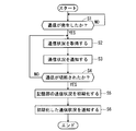
- FIG. 2 is a flowchart showing a processing procedure of the wireless communication apparatus 1 relating to a communication status monitoring process.
- Each process of the flowchart illustrated in FIG. 2 is executed by the overall control unit 20, the communication CH management unit 21, the wireless communication control unit 22, and the wireless communication unit 12.
- the process proceeds to step S1 and the processing procedure of this flowchart is started.
- step S1 the wireless communication control unit 22 determines whether communication has occurred. If it is determined in step S1 that communication has occurred, the process proceeds to step S2, and if it is determined that communication has not occurred, the process waits until communication occurs.
- the wireless communication control unit 22 determines whether or not communication has occurred depending on whether or not communication between the wireless communication device 1 and the counterpart device 2 has been established. That is, the wireless communication control unit 22 determines that communication has occurred when communication with the counterpart device 2 has been established, and communication has occurred when communication with the counterpart device 2 has not been established. Judge that there is no.
- step S ⁇ b> 2 the communication CH management unit 21 acquires the current communication status from the wireless communication control unit 22. For example, when the communication status is empty communication channel information, the communication CH management unit 21 checks the packet type of the packet currently used for communication with the counterpart device 2 via the wireless communication control unit 22.
- the communication CH management unit 21 calculates a free communication channel, which is a channel that is not currently used, based on the confirmed packet type.
- the communication CH management unit 21 holds the empty communication channel information indicating the calculated empty communication channel as the communication status. When the communication status is acquired in this way, the process proceeds to step S3.
- step S3 the communication CH management unit 21 notifies the display output device 14 of the communication status acquired in step S2 via the overall control unit 20 and the display output control unit 24.
- the display output device 14 displays a video representing the notified communication status. As a result, the communication status is notified to the user by video.
- the communication CH management unit 21 notifies the overall control unit 20 of the communication status acquired in step S2.
- the overall control unit 20 generates video data for display based on the notified communication status, and provides the generated video data to the display output control unit 24.
- the display output control unit 24 converts the video data given from the overall control unit 20 into a video signal and gives it to the display output device 14.
- the display output device 14 displays a video based on the video signal given from the display output control unit 24. In this way, the display output device 14 displays a video representing the communication status. As a result, the communication status is notified to the user by video.
- the overall control unit 20 stores the communication status notified from the communication CH management unit 21 in the storage unit 11 as communication status information.
- the process proceeds to step S4.
- the communication CH management unit 21 may notify the audio output device 15 of the communication status acquired in step S2 via the overall control unit 20 and the audio output control unit 25.
- the overall control unit 20 generates audio data based on the communication status notified from the communication CH management unit 21 and gives the audio data to the audio output control unit 25.
- the voice output control unit 25 converts the voice data given from the overall control unit 20 into a voice signal and gives the voice signal to the voice output device 15.
- the audio output device 15 outputs audio based on the audio signal given from the audio output control unit 25. In this manner, the voice output device 15 outputs a voice representing the communication status. As a result, the communication status is notified to the user by voice.
- the notification of the communication status to the user in step S3 may be performed in either one of video and audio, or may be performed in both.
- step S4 the wireless communication control unit 22 determines whether or not the communication between the wireless communication device 1 and the counterpart device 2 has been disconnected. If it is determined in step S4 that the communication has been disconnected, the process proceeds to step S5. If it is determined that the communication has not been disconnected, the process returns to step S2.
- step S5 the communication CH management unit 21 initializes the communication status stored in the storage unit 11 via the overall control unit 20. Specifically, the communication CH management unit 21 erases the communication status stored in the storage unit 11 in step S3 from the storage unit 11 via the overall control unit 20. When the communication status is initialized, the process proceeds to step S6.
- Step S6 the communication CH management unit 21 notifies the display output device 14 of the initialized communication status via the overall control unit 20 and the display output control unit 24, and the display output device 14 notifies the notified communication status.
- a video representing is displayed.
- step S3 If the communication CH management unit 21 notifies the voice output device 15 of the communication status in step S3, the communication status that has been initialized in step S6 is sent to the voice output device via the overall control unit 20 and the voice output control unit 25. 15, the voice output device 15 outputs a voice representing the notified communication status. Thereby, all processing procedures are completed.
- the communication CH management unit 21 calculates an empty communication channel as follows.
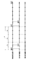
- 3 and 4 are diagrams illustrating an example of a transmission / reception state of communication packets in wireless communication between the wireless communication device 1 and the counterpart device 2.
- FIG. 3 and 4 show a case where wireless communication is performed using Bluetooth.
- FIG. 3 shows an example in which the wireless communication device 1 is communicating with only the first counterpart device A1 using HV3 packets.
- the communication CH management unit 21 confirms that the packet type of the packet being used is HV3.
- the transmission cycle F of the HV3 packet is 3.75 msec, which corresponds to three time slots TS that are a combination of a communication slot used for transmission and a communication slot used for reception. That is, the HV3 packet is transmitted and received in one time slot TS among the three time slots TS included in one transmission period F.
- the wireless communication device 1 can wirelessly communicate with other counterpart devices 2 in the remaining two time slots TS. Therefore, the communication CH management unit 21 calculates the empty slot corresponding to the empty communication channel as “2”.
- the communication CH management unit 21 subtracts the value obtained by subtracting the “number of counterpart devices 2 in communication” from the “number of time slots TS included in one transmission cycle F”, that is, the number of empty slots, that is, Calculated as the number of free communication channels.
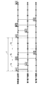
- FIG. 4 shows an example in which the wireless communication device 1 communicates with the first counterpart device A1 and the second counterpart device A2 using HV3 packets.
- HV3 packets transmitted / received to / from the first counterpart device A1 are indicated by white blocks
- HV3 packets transmitted / received to / from the second counterpart device A2 are indicated by hatching.
- the empty slot to be calculated is calculated as “1”.
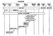
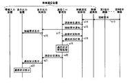
- 5 to 7 are diagrams illustrating an example of a sequence in the wireless communication device 1 when the communication status is displayed on the display output device 14. 5 to 7, when the wireless communication device 1 is in the operating state at step a1, the first counterpart device A1 is in the operating state at step a2, and the Nth device AN is at the operating state at step a3. Indicates.
- step a4 the user operates the information input device 13 to input a connection request for requesting connection with the first counterpart device A1, and the input connection request is used as a connection request signal as an information input control unit.
- 23 and the overall control unit 20 are transmitted to the communication CH management unit 21.
- step a5 the wireless communication device 1 performs processing for establishing communication with the first counterpart device A1. As a result, the wireless communication device 1 and the first counterpart device A1 enter a communication state.
- step a6 the wireless communication control unit 22 notifies the communication CH management unit 21 of a communication generation signal indicating that communication has occurred. To do.
- step a7 the communication CH management unit 21 transmits to the wireless communication control unit 22 an acquisition request signal representing a communication status acquisition request for requesting acquisition of the current communication status.
- step a8 the wireless communication control unit 22 acquires the current communication status and transmits a communication status signal representing the acquired communication status to the communication CH management unit 21 as a response signal to the acquisition request signal.
- step a9 the communication CH management unit 21 performs a communication status management process for managing the communication status represented by the communication status signal received from the wireless communication control unit 22 in step a8.
- the communication CH management unit 21 stores the communication status represented by the communication status signal received from the wireless communication control unit 22 in the storage unit 11 via the overall control unit 20 as communication status management processing. Process.
- step a10 the communication CH management unit 21 notifies the display output control unit 24 of the communication status signal received from the wireless communication control unit 22 in step a8 via the overall control unit 20.
- step a11 the display output control unit 24 transmits to the display output device 14 a display instruction signal indicating an instruction to display the communication status based on the communication status signal notified from the communication CH management unit 21 in step a10.
- step a12 the display output device 14 displays the communication status based on the display instruction signal received from the display output control unit 24.
- step a ⁇ b> 13 the Nth counterpart device AN transmits a connection request signal for requesting connection with the own device to the wireless communication device 1.
- the connection request signal transmitted to the wireless communication device 1 is received by the wireless communication control unit 22 via the wireless communication unit 12 of the wireless communication device 1.
- the wireless communication control unit 22 When receiving the connection request signal, the wireless communication control unit 22 notifies the communication CH management unit 21 of a communication generation signal indicating that communication has occurred in step a14. In step a15, the wireless communication control unit 22 notifies the display output control unit 24 of the connection request signal via the communication CH management unit 21 and the overall control unit 20.
- step a16 the display output control unit 24 transmits to the display output device 14 a connection request display instruction signal indicating an instruction to display that there is a connection request.
- the display output device 14 displays that there is a connection request.
- step a17 the communication CH management unit 21 transmits an acquisition request signal for requesting acquisition of the current communication status to the wireless communication control unit 22.
- step a18 the wireless communication control unit 22 acquires the current communication status, and transmits a communication status signal representing the acquired communication status to the communication CH management unit 21 as a response signal to the acquisition request signal.
- step a19 the communication CH management unit 21 performs a communication status management process for managing the communication status represented by the communication status signal received from the wireless communication control unit 22 in step a18.
- step a20 the communication CH management unit 21 notifies the display output control unit 24 of the communication status signal received from the wireless communication control unit 22 in step a18 via the overall control unit 20.
- step a21 the display output control unit 24 transmits to the display output device 14 a display instruction signal indicating an instruction to display the communication status based on the communication status signal notified from the communication CH management unit 21 in step a20.
- step a ⁇ b> 22 the display output device 14 displays the communication status based on the display instruction signal received from the display output control unit 24.
- step a23 the user operates the information input device 13 to input a connection response instruction indicating an instruction to respond to the connection request from the Nth counterpart device AN.
- the input connection response instruction is a connection response instruction.
- a signal is transmitted to the communication CH management unit 21 via the information input control unit 23 and the overall control unit 20.
- the wireless communication device 1 In response to the connection response instruction signal transmitted in step a23, the wireless communication device 1 performs processing for establishing communication with the Nth counterpart device AN in step a24. As a result, the wireless communication device 1 and the Nth counterpart device AN enter a communication state. Therefore, at this time, the wireless communication device 1, the first counterpart device A1, and the Nth counterpart device AN are in a communication state.
- step a25 the wireless communication control unit 22 notifies the communication CH management unit 21 of a communication generation signal indicating that communication has occurred. To do.
- step a26 the communication CH management unit 21 transmits an acquisition request signal requesting acquisition of the current communication status to the wireless communication control unit 22.
- step a ⁇ b> 27 the wireless communication control unit 22 acquires a communication status, and transmits a communication status signal representing the acquired communication status to the communication CH management unit 21 as a response signal to the acquisition request signal.
- step a28 the communication CH management unit 21 performs a communication status management process for managing the communication status represented by the communication status signal received from the wireless communication control unit 22 in step a27. Specifically, the communication CH management unit 21 performs processing for storing the communication status represented by the received communication status signal in the storage unit 11 via the overall control unit 20.
- step a29 the communication CH management unit 21 notifies the display output control unit 24 of the communication status signal received from the wireless communication control unit 22 in step a27 via the overall control unit 20.
- step a30 the display output control unit 24 transmits to the display output device 14 a display instruction signal indicating an instruction to display the communication status based on the communication status signal notified from the communication CH management unit 21 in step a29.
- step a ⁇ b> 31 the display output device 21 displays the communication status based on the display instruction signal received from the display output control unit 24.
- FIG. 8 is a perspective view showing the appearance of the wireless communication device 1.
- the CPU 10, the storage unit 11, the wireless communication unit 12, the information input device 13, and the display output device 14 illustrated in FIG. 1 are provided in a wireless communication device main body (hereinafter referred to as “device main body”) 30.
- the audio output device 15, for example, a speaker, is provided separately from the device main body 30 and connected to the device main body 30.
- the display output device 14 displays the communication status on, for example, the communication status display unit 32 provided in a part of the display screen 31.
- the audio output device 15 outputs the communication status as audio.
- the operation unit 33 of the information input device 13 is provided below the display screen 31, for example. The user inputs a connection request or the like by operating the operation unit 33.
- FIGS. 9 to 12 are diagrams showing display examples of the communication status in the wireless communication device 1.
- FIG. 9 to 12 show a case where an empty communication channel is displayed as the communication status on the communication status display unit 32 of the display output device 14 shown in FIG.
- the display examples shown in FIGS. 9 to 12 are display examples when communication is performed using HV3 packets. In communication using the HV3 packet, communication is performed using three channels, so the communication status display unit 32 is configured to include, for example, three indicators 41 to 43.
- each indicator 41 to 43 is configured to be switchable between a lighting state and a light-off state. At the stage when the power of the wireless communication apparatus 1 is turned on, all the indicators 41 to 43 are turned off.
- the three indicators 41 to 43 are turned on in the order of the first indicator 41, the second indicator 42, and the third indicator 43 according to the number of used channels, and switched from the off state to the on state.
- the number of indicators 41 to 43 in the off state corresponds to the number of empty communication channels.
- the wireless communication device 1 When the wireless communication device 1 is performing wireless communication with one counterpart device 2, since one channel is used, there are two free communication channels. In this case, as shown in FIG. 10, among the three indicators 41 to 43, the first indicator 41 is turned on and is turned on. The remaining second and third indicators 42 and 43 are not turned on but are turned off. This notifies the user that there are two free communication channels.
- the wireless communication device 1 When the wireless communication device 1 is wirelessly communicating with two counterpart devices 2, since two channels are used, there is one free communication channel.
- the first and second indicators 41 and 42 are lit and turned on.
- the remaining third indicator 43 is not turned on and is turned off. As a result, the user is notified that there is one free communication channel.
- the wireless communication device 1 When the wireless communication device 1 is wirelessly communicating with the three counterpart devices 2, all three channels are used, so the free communication channel is zero (0). In this case, as shown in FIG. 12, all of the three indicators 41 to 43 are turned on and turned on, and the extinguished indicators 41 to 43 are lost. This notifies the user that the free communication channel is zero (0), that is, there is no free communication channel.
- the communication status of the wireless communication device 1 sequentially changes to the states shown in FIGS. 9 to 12, for example.
- the connection with one counterpart device 2 is disconnected from the state where there is no free communication channel as shown in FIG. 12 and a free communication channel is created as shown in FIG. 11, the audio output device 15 shown in FIG.
- the user may be notified from the speaker that a free communication channel has been established.
- the user can immediately recognize that a free communication channel has been created, and can promptly request the wireless communication apparatus 1 to connect to a new counterpart device 2.
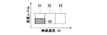
- FIG. 13 and 14 are diagrams showing other display examples of the communication status in the wireless communication device 1.
- the communication status display unit 32 includes three indicators 51 to 53 shown in FIGS.
- the indicators 51 to 53 shown in FIGS. 13 and 14 are configured in the same manner as the indicators 41 to 43 shown in FIGS. In the following description, the first indicator 51, the second indicator 52, and the third indicator 53 are referred to in order from the left side of FIGS. Each of the indicators 51 to 53 can be switched between a lighting state and a light-off state.
- the indicators 51 to 53 are turned off.
- the three indicators 51 to 53 are turned on in the order of the first indicator 51, the second indicator 52, and the third indicator 53 in accordance with the number of used channels, and switched from the off state to the on state.
- the number of indicators 51 to 53 that are lit represents the number of wireless communication channels (ch) that are being used. In other words, the number of indicators 51 to 53 in the off state represents the number of free communication channels.
- each of the indicators 51 to 53 is configured to change the area of the area to be lit (hereinafter referred to as “lighting area”) according to the reception level of the wireless communication channel.
- the area of the lighting area of each indicator 51 to 53 represents the reception level of each wireless communication channel.
- the area of the lighting region of each indicator 51 to 53 is changed by changing the length of the lighting region in the short direction of the communication status display unit 32, that is, the vertical direction in FIGS.
- FIG. 13 is a display example when the wireless communication channel being used is one channel and the reception level is half the maximum value.
- the wireless communication channel being used is one channel and the reception level is half the maximum value.
- the three indicators 51 to 53 only the first indicator 51 at the left end in FIG. 13 is lit and turned on.
- the remaining second and third indicators 52 and 53 are turned off. This notifies the user that there are two free communication channels.
- the first indicator 51 is lit only in the lower half of FIG. This notifies the user that the reception level of the wireless communication channel being used is half of the maximum value.
- the lighting area 50 of the first indicator 51 is displayed in a different display color according to the reception level. For example, as shown in FIG. 13, when the reception level is half of the maximum value, the lighting area 50 of the first indicator 51 is displayed in yellow green.
- FIG. 14 is a display example when the wireless communication channel being used is one channel, the reception level is a half of the maximum value, and an error has occurred.
- the lighting area 55 of the first indicator 51 is displayed in a display color different from the display color when the error shown in FIG. 13 has not occurred, for example, yellow. The Thus, by changing the display colors of the indicators 51 to 53 depending on the presence or absence of an error, it is possible to notify the user that an error has occurred.
- the communication CH management unit 21 calculates a free communication channel based on the communication status acquired by the wireless communication control unit 22.
- the communication status includes the packet type of the communication packet being used. Based on this packet type, a free communication channel is calculated.
- an empty communication channel can be obtained without providing a means for obtaining the communication status, such as a means for measuring the received radio wave intensity. Therefore, an empty communication channel can be obtained with a simple configuration.
- the notification information including the available communication channel information regarding the obtained available communication channel is output by either one or both of the display output device 14 and the audio output device 15.
- notification information including free communication channel information can be notified to the user, so that the user can accurately determine the current communication status and avoid unnecessary connections.
- the notification information including the free communication channel information is output as a video by the display output device 14, so that the notification information including the free communication channel information can be visually notified to the user. Therefore, the user can easily grasp the current communication status including the empty communication channel.
- notification information including free communication channel information can be output as audio by the audio output device 15.
- the user can be notified of notification information including free communication channel information.
- the wireless communication device 1 is a navigation device and is used in an automobile
- the user is notified of notification information including free communication channel information even when the user is driving the automobile. be able to. Therefore, the user can quickly grasp the current communication status including the empty communication channel.
- the communication status acquired by the communication CH management unit 21 includes the reception level and the presence / absence of an error
- the notification information output from the display output device 14 and the audio output device 15 includes the reception level information and Contains error information.
- the reception level information is displayed on the communication status display unit 32 of the display screen 14 of the display output device 14 as the area of the lighting region 50 of the indicator 51 as shown in FIGS. 13 and 14, for example.
- the error information is displayed as the display color of the lighting area 55 of the indicator 51, for example, as shown in FIG.
- the display output device 14 and the audio output device 15 or the like by outputting at least one of the reception level information and the error information by the display output device 14 and the audio output device 15 or the like, it is possible to notify the user of a more detailed communication status. As a result, the user can more accurately determine the current communication status, so that unnecessary connections can be avoided more reliably.
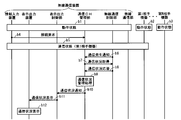
- the communication status is displayed on the display output device 14 of the wireless communication device 1, but may be displayed on the display output device of the counterpart device 2.
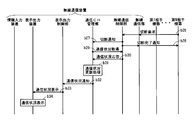
- FIGS. 15 to 17 are diagrams showing an example of a sequence when the communication status is displayed on the display output device of the counterpart device 2. 15 to 17, in step b1, the wireless communication device 1 is in an operating state, in step b2, the first counterpart device A1 is in an operating state, and in step b3, the Nth counterpart device AN is in an operating state. Show the case.
- step b4 the user operates the information input device 13 to input a connection request for requesting connection with the first counterpart device A1, and the input connection request is used as a connection request signal as an information input control unit.
- 23 and the overall control unit 20 are transmitted to the communication CH management unit 12.
- step b5 Upon receiving the connection request signal in step b4, in step b5, the wireless communication device 1 performs processing for establishing communication with the first counterpart device N1. As a result, the wireless communication device 1 and the first counterpart device A1 enter a communication state.
- step b6 the wireless communication control unit 22 notifies the communication CH management unit 21 of a communication generation signal indicating that communication has occurred. To do.
- step b7 the communication CH management unit 21 transmits an acquisition request signal for requesting acquisition of the current communication status to the wireless communication control unit 22.
- step b8 the wireless communication control unit 22 acquires the communication status, and transmits a communication status signal representing the acquired communication status to the communication CH management unit 21 as a response signal to the acquisition request signal.
- step b9 the communication CH management unit 21 performs a communication status management process for managing the communication status represented by the communication status signal received from the wireless communication control unit 22 in step b8.
- the communication CH management unit 21 stores a communication state represented by a communication state signal received from the wireless communication control unit 22 in the storage unit 11 via the overall control unit 20 as a communication state management process. Do.
- step b10 the communication CH management unit 21 notifies the display output control unit 24 of the communication status signal received from the wireless communication control unit 22 in step b8 via the overall control unit 20.
- step b11 the display output control unit 24 transmits to the display output device 14 a display instruction signal representing an instruction to display the communication status based on the communication status signal notified from the communication CH management unit 21 in step b10.
- step b12 the display output device 14 displays the communication status based on the display instruction signal received from the display output control unit 24.
- step b13 of FIG. 16 is performed following the process of step b12 of FIG.
- step b13 the Nth counterpart device AN transmits a communication status request signal for requesting notification of the communication status to the wireless communication device 1.
- the communication status request signal transmitted to the wireless communication device 1 is received by the wireless communication control unit 22 via the wireless communication unit 12 of the wireless communication device 1.
- the wireless communication control unit 22 When receiving the communication status request signal, the wireless communication control unit 22 transmits the communication status request signal to the communication CH management unit 21 in step b14. In response to the communication status request signal transmitted in step b14, in step b15, the wireless communication device 1 performs processing for establishing communication with the Nth counterpart device AN. As a result, the wireless communication device 1 and the Nth counterpart device AN enter a communication state. Therefore, at this time, the wireless communication device 1, the first counterpart device A1, and the Nth counterpart device AN are in a communication state.
- step b16 the wireless communication control unit 22 notifies the communication CH management unit 21 of a communication generation signal indicating that communication has occurred. To do.
- step b17 the communication CH management unit 21 transmits to the wireless communication control unit 22 an acquisition request signal for requesting acquisition of the current communication status.
- step b18 the wireless communication control unit 22 acquires the communication status, and transmits a communication status signal indicating the acquired communication status to the communication CH management unit 21 as a response signal to the acquisition request signal.
- step b19 the communication CH management unit 21 performs a communication status update process for updating the communication status represented by the communication status signal received from the wireless communication control unit 22 in step b18. Specifically, the communication CH management unit 21 updates the communication status stored in the storage unit 11 via the overall control unit 20 by rewriting the communication status represented by the communication status signal received in step b18. Perform the process.
- step b20 the communication CH management unit 21 notifies the display output control unit 24 of the communication status signal received from the wireless communication control unit 22 in step b18 via the overall control unit 20.
- step b21 the communication CH management unit 21 transmits the communication status signal received from the radio communication control unit 22 in step b18 to the radio communication control unit 22 as a response signal to the communication status request signal.
- step b22 the display output control unit 24 transmits to the display output device 14 a display instruction signal indicating an instruction to display the communication status based on the communication status signal notified from the communication CH management unit 21 in step b20.
- step b23 the display output device 14 displays the communication status based on the display instruction signal received from the display output control unit 24.
- step b24 the wireless communication control unit 22 transmits the communication status signal received from the communication CH management unit 21 in step b21 to the Nth counterpart device AN as a response signal of the communication status request signal.
- step b25 the Nth counterpart device AN displays the communication status represented by the communication status signal received in step b24 on its own display output device.
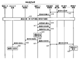
- step b26 of FIG. 17 is performed following the process of step b25 of FIG.
- the Nth counterpart device AN transmits to the wireless communication apparatus 1 a disconnection request signal indicating a communication disconnection request for requesting disconnection of communication with the own device.
- the disconnection request signal transmitted to the wireless communication device 1 is received by the wireless communication control unit 22 via the wireless communication unit 12 of the wireless communication device 1.
- the wireless communication control unit 22 receives the disconnection request signal
- the wireless communication device 1 performs communication disconnection processing for disconnecting communication with the Nth counterpart device AN, and the process proceeds to step b27.
- step b27 the wireless communication control unit 22 notifies the communication CH management unit 21 of a disconnection signal indicating that the communication with the Nth counterpart device AN has been disconnected.
- step b28 the wireless communication control unit 22 transmits a disconnection completion signal indicating that the communication disconnection process has been completed to the Nth partner device AN via the wireless communication unit 12.
- step b29 the communication CH management unit 21 transmits an acquisition request signal for requesting acquisition of the current communication status to the wireless communication control unit 12.
- step b30 the wireless communication control unit 22 acquires the communication status, and transmits a communication status signal representing the acquired communication status to the communication CH management unit 21 as a response signal to the acquisition request signal.
- step b31 the communication CH management unit 21 performs a communication status update process for updating the communication status represented by the communication status signal received from the wireless communication control unit 22 in step b30. Specifically, the communication CH management unit 21 updates the communication status stored in the storage unit 11 via the overall control unit 20 by rewriting the communication status represented by the communication status signal received in step b30. Perform the process.
- step b32 the communication CH management unit 21 notifies the display output control unit 24 of the communication status signal received from the wireless communication control unit 22 in step b30 via the overall control unit 20.
- step b ⁇ b> 33 the display output control unit 24 transmits a display instruction signal indicating an instruction to display the communication status based on the communication status signal notified from the communication CH management unit 21 in step b ⁇ b> 32 to the display output device 14.
- step b ⁇ b> 34 the display output device 14 displays the communication status based on the display instruction signal received from the display output control unit 24.
- the notification information including the empty communication channel information is transmitted to the counterpart device 2 by the wireless communication unit 12, so that the display output device and the voice output device of the counterpart device 2 can output the notification information.
- notification information including free communication channel information can be displayed on the display output device of the counterpart device 2.
- the user can more easily grasp the current communication status including the empty communication channel. can do.
Abstract
Description
Claims (10)
- ブルートゥースを利用して、相手機器と無線通信を行う無線通信手段と、
前記無線通信手段によって行われる前記無線通信の通信状況を取得する状況取得手段と、
前記状況取得手段によって取得される前記通信状況に基づいて、前記無線通信手段が前記無線通信で使用可能な空き通信チャネルを算出するチャネル算出手段とを備え、
前記通信状況は、使用されている通信パケットのパケットタイプを含み、
前記チャネル算出手段は、前記パケットタイプに基づいて、前記空き通信チャネルを算出することを特徴とする無線通信装置。 Wireless communication means for performing wireless communication with a partner device using Bluetooth;
Status acquisition means for acquiring a communication status of the wireless communication performed by the wireless communication means;
Based on the communication status acquired by the status acquisition means, the wireless communication means comprises a channel calculation means for calculating an available communication channel usable in the wireless communication,
The communication status includes the packet type of the communication packet being used,
The wireless communication apparatus, wherein the channel calculation means calculates the free communication channel based on the packet type. - 前記チャネル算出手段によって算出される前記空き通信チャネルに関する空き通信チャネル情報を含む通知情報を映像として出力する表示出力手段を備えることを特徴とする請求項1に記載の無線通信装置。 The wireless communication apparatus according to claim 1, further comprising display output means for outputting notification information including free communication channel information related to the free communication channel calculated by the channel calculation means as video.
- 前記チャネル算出手段によって算出される前記空き通信チャネルに関する空き通信チャネル情報を含む通知情報を音声として出力する音声出力手段を備えることを特徴とする請求項1に記載の無線通信装置。 The wireless communication apparatus according to claim 1, further comprising: voice output means for outputting notification information including free communication channel information related to the free communication channel calculated by the channel calculation means as sound.
- 前記無線通信手段は、前記チャネル算出手段によって算出される前記空き通信チャネルに関する空き通信チャネル情報を含む通知情報を、前記相手機器に送信することを特徴とする請求項1に記載の無線通信装置。 The wireless communication apparatus according to claim 1, wherein the wireless communication unit transmits notification information including free communication channel information related to the free communication channel calculated by the channel calculation unit to the counterpart device.
- 前記通信状況は、受信レベルおよびエラーの有無の少なくとも一方を含み、
前記通知情報は、前記受信レベルに関する受信レベル情報、および前記エラーの有無に関するエラー情報の少なくとも一方を含むことを特徴とする請求項2に記載の無線通信装置。 The communication status includes at least one of reception level and presence / absence of error,
The wireless communication apparatus according to claim 2, wherein the notification information includes at least one of reception level information regarding the reception level and error information regarding presence / absence of the error. - ブルートゥースを利用して、相手機器と無線通信を行う無線通信方法であって、
前記無線通信の通信状況を取得する状況取得ステップと、
前記状況取得ステップで取得される前記通信状況に基づいて、前記無線通信で使用可能な空き通信チャネルを算出するチャネル算出ステップとを備え、
前記通信状況は、使用されている通信パケットのパケットタイプを含み、
前記チャネル算出ステップでは、前記パケットタイプに基づいて、前記空き通信チャネルを算出することを特徴とする無線通信方法。 A wireless communication method for performing wireless communication with a counterpart device using Bluetooth,
A status acquisition step of acquiring a communication status of the wireless communication;
A channel calculation step of calculating a free communication channel that can be used in the wireless communication based on the communication status acquired in the status acquisition step;
The communication status includes the packet type of the communication packet being used,
In the channel calculation step, the free communication channel is calculated based on the packet type. - 前記チャネル算出ステップで算出される前記空き通信チャネルに関する空き通信チャネル情報を含む通知情報を、表示出力手段によって映像として出力するステップを備えることを特徴とする請求項6に記載の無線通信方法。 The wireless communication method according to claim 6, further comprising a step of outputting notification information including free communication channel information related to the free communication channel calculated in the channel calculating step as video by a display output means.
- 前記チャネル算出ステップで算出される前記空き通信チャネルに関する空き通信チャネル情報を含む通知情報を、音声出力手段によって音声として出力するステップを備えることを特徴とする請求項6に記載の無線通信方法。 The wireless communication method according to claim 6, further comprising a step of outputting, as voice, notification information including idle communication channel information related to the idle communication channel calculated in the channel calculating step.
- 前記チャネル算出ステップで算出される前記空き通信チャネルに関する空き通信チャネル情報を含む通知情報を、前記相手機器に送信するステップを備えることを特徴とする請求項6に記載の無線通信方法。 The wireless communication method according to claim 6, further comprising a step of transmitting notification information including free communication channel information related to the free communication channel calculated in the channel calculating step to the counterpart device.
- 前記通信状況は、受信レベルおよびエラーの有無の少なくとも一方を含み、
前記通知情報は、前記受信レベルに関する受信レベル情報、および前記エラーの有無に関するエラー情報の少なくとも一方を含むことを特徴とする請求項7に記載の無線通信方法。 The communication status includes at least one of reception level and presence / absence of error,
The wireless communication method according to claim 7, wherein the notification information includes at least one of reception level information regarding the reception level and error information regarding presence or absence of the error.
Priority Applications (5)
| Application Number | Priority Date | Filing Date | Title |
|---|---|---|---|
| US14/354,169 US20140269602A1 (en) | 2012-01-13 | 2012-01-13 | Wireless communication device and wireless communication method |
| JP2013553161A JP5606641B2 (en) | 2012-01-13 | 2012-01-13 | Wireless communication apparatus and wireless communication method |
| CN201280066789.XA CN104041132B (en) | 2012-01-13 | 2012-01-13 | Radio communication device and wireless communications method |
| PCT/JP2012/050585 WO2013105263A1 (en) | 2012-01-13 | 2012-01-13 | Wireless communication device and wireless communication method |
| DE112012005658.2T DE112012005658B4 (en) | 2012-01-13 | 2012-01-13 | Radio communication device and radio communication method |
Applications Claiming Priority (1)
| Application Number | Priority Date | Filing Date | Title |
|---|---|---|---|
| PCT/JP2012/050585 WO2013105263A1 (en) | 2012-01-13 | 2012-01-13 | Wireless communication device and wireless communication method |
Publications (1)
| Publication Number | Publication Date |
|---|---|
| WO2013105263A1 true WO2013105263A1 (en) | 2013-07-18 |
Family
ID=48781233
Family Applications (1)
| Application Number | Title | Priority Date | Filing Date |
|---|---|---|---|
| PCT/JP2012/050585 WO2013105263A1 (en) | 2012-01-13 | 2012-01-13 | Wireless communication device and wireless communication method |
Country Status (5)
| Country | Link |
|---|---|
| US (1) | US20140269602A1 (en) |
| JP (1) | JP5606641B2 (en) |
| CN (1) | CN104041132B (en) |
| DE (1) | DE112012005658B4 (en) |
| WO (1) | WO2013105263A1 (en) |
Families Citing this family (3)
| Publication number | Priority date | Publication date | Assignee | Title |
|---|---|---|---|---|
| JP6445742B1 (en) | 2015-10-21 | 2018-12-26 | セント・ジュード・メディカル,カーディオロジー・ディヴィジョン,インコーポレイテッド | High density electrode mapping catheter |
| CN106658379A (en) * | 2016-12-30 | 2017-05-10 | 贵州财富之舟科技有限公司 | Communication method, device and system for Bluetooth device |
| WO2020039392A2 (en) | 2018-08-23 | 2020-02-27 | St. Jude Medical, Cardiology Division, Inc. | Curved high density electrode mapping catheter |
Citations (1)
| Publication number | Priority date | Publication date | Assignee | Title |
|---|---|---|---|---|
| JP2002300089A (en) * | 2001-03-29 | 2002-10-11 | Pioneer Electronic Corp | Radio communication unit of frequency hopping type |
Family Cites Families (18)
| Publication number | Priority date | Publication date | Assignee | Title |
|---|---|---|---|---|
| JPH04213932A (en) * | 1990-12-11 | 1992-08-05 | Fujitsu Ltd | Channel state display device for cordless telephone set |
| JPH06237204A (en) * | 1993-02-10 | 1994-08-23 | Hitachi Ltd | Radio calling system and receiving equipment |
| JP2908379B2 (en) * | 1997-05-14 | 1999-06-21 | 日本電気通信システム株式会社 | Simple mobile phone system |
| DE60030086T2 (en) * | 2000-01-20 | 2007-01-04 | Lucent Technologies Inc. | Interoperability of Bluetooth and IEEE 802.11 |
| JP2002344378A (en) * | 2001-05-21 | 2002-11-29 | Pioneer Electronic Corp | Radio communication terminal |
| US6842607B2 (en) * | 2002-09-09 | 2005-01-11 | Conexant Systems, Inc | Coordination of competing protocols |
| JP2004187089A (en) * | 2002-12-04 | 2004-07-02 | Matsushita Electric Ind Co Ltd | Wireless communication system and method for searching idle channel |
| CN1965503B (en) * | 2004-06-07 | 2012-10-31 | Nxp股份有限公司 | System and method for operating different mutually adjacent transreceivers |
| US8719419B2 (en) * | 2005-04-21 | 2014-05-06 | Qualcomm Incorporated | Methods and apparatus for determining aspects of multimedia performance of a wireless device |
| US7844222B2 (en) * | 2006-05-24 | 2010-11-30 | Broadcom Corporation | Method and system for changing priority of slave frames in multiwire coexistence |
| US7899396B2 (en) * | 2006-06-02 | 2011-03-01 | Qulacomm Incorporated | Efficient operation for co-located WLAN and Bluetooth |
| US8204036B2 (en) * | 2007-02-28 | 2012-06-19 | Motorola Mobility, Inc. | Method and apparatus for coexistence |
| US8121144B2 (en) * | 2007-11-20 | 2012-02-21 | Altair Semiconductor Ltd. | Multi-function wireless terminal |
| US8184566B2 (en) * | 2009-06-05 | 2012-05-22 | Mediatek Inc. | Systems for wireless local area network (WLAN) transmission and for coexistence of WLAN and another type of wireless transmission and methods thereof |
| US8774722B2 (en) * | 2009-07-09 | 2014-07-08 | Mediatek Inc. | Systems and methods for reducing interference between a plurality of wireless communications modules |
| US8737917B2 (en) * | 2009-07-24 | 2014-05-27 | Broadcom Corporation | Method and system for a dual-mode bluetooth low energy device |
| CN102036125B (en) * | 2009-09-29 | 2013-02-13 | 徐佳义 | Portable digital radio group navigation system |
| KR20110064528A (en) * | 2009-12-08 | 2011-06-15 | 삼성전자주식회사 | Method and apparatus for transmitting data in a bluetooth device |
-
2012
- 2012-01-13 JP JP2013553161A patent/JP5606641B2/en active Active
- 2012-01-13 US US14/354,169 patent/US20140269602A1/en not_active Abandoned
- 2012-01-13 DE DE112012005658.2T patent/DE112012005658B4/en active Active
- 2012-01-13 CN CN201280066789.XA patent/CN104041132B/en active Active
- 2012-01-13 WO PCT/JP2012/050585 patent/WO2013105263A1/en active Application Filing
Patent Citations (1)
| Publication number | Priority date | Publication date | Assignee | Title |
|---|---|---|---|---|
| JP2002300089A (en) * | 2001-03-29 | 2002-10-11 | Pioneer Electronic Corp | Radio communication unit of frequency hopping type |
Also Published As
| Publication number | Publication date |
|---|---|
| DE112012005658B4 (en) | 2016-01-07 |
| JPWO2013105263A1 (en) | 2015-05-11 |
| CN104041132B (en) | 2016-01-20 |
| CN104041132A (en) | 2014-09-10 |
| US20140269602A1 (en) | 2014-09-18 |
| DE112012005658T5 (en) | 2014-11-06 |
| JP5606641B2 (en) | 2014-10-15 |
Similar Documents
| Publication | Publication Date | Title |
|---|---|---|
| CN110168942B (en) | Method, terminal, system and storage medium for selecting Bluetooth device | |
| JP5273215B2 (en) | Near field communication device | |
| US8600431B2 (en) | Communication apparatus, communication system, and method for connecting devices | |
| US8260369B2 (en) | Vehicle hands-free communication apparatus and vehicle hands-free communication method | |
| CN110518707B (en) | Transmitting terminal device, receiving terminal device and wireless charging method | |
| WO2015069651A1 (en) | Session quality display in a wireless communication system | |
| JP5606641B2 (en) | Wireless communication apparatus and wireless communication method | |
| JP2016073270A (en) | Remote control system of electric fishing reel | |
| US20090268620A1 (en) | Communication connecting method, communication connecting device and storage medium with program stored therein | |
| KR20110076520A (en) | Apparatus and method of car bluetooth interface | |
| JP2012129765A (en) | Electronic device | |
| JP2012533951A (en) | Bluetooth device detection device and process | |
| US8503935B2 (en) | Terminal and method for controlling function using short-distance communication | |
| US9769298B2 (en) | Cordless phone apparatus, cordless phone system, and method for transferring data | |
| WO2013054456A1 (en) | Control device and wireless communication system | |
| US10439416B2 (en) | Method for outputting charging current according to displayed media and power amplifier | |
| JP2009206711A (en) | Communication terminal | |
| JP2015104098A (en) | Radio communication system and radio communication method | |
| KR102480327B1 (en) | Electronic device using a bluetooth communication and method of operating the same | |
| KR20130066722A (en) | Interlocking type avn terminal and method driving thereof | |
| JP6608301B2 (en) | Communication device | |
| JP2008186354A (en) | Transmitter and radio communication system | |
| JP6328492B2 (en) | Battery level check device | |
| JP2013138277A (en) | Relay device, output system, output method, and computer program | |
| WO2015145678A1 (en) | Communication control device |
Legal Events
| Date | Code | Title | Description |
|---|---|---|---|
| 121 | Ep: the epo has been informed by wipo that ep was designated in this application |
Ref document number: 12865190 Country of ref document: EP Kind code of ref document: A1 |
|
| ENP | Entry into the national phase |
Ref document number: 2013553161 Country of ref document: JP Kind code of ref document: A |
|
| WWE | Wipo information: entry into national phase |
Ref document number: 14354169 Country of ref document: US |
|
| WWE | Wipo information: entry into national phase |
Ref document number: 112012005658 Country of ref document: DE Ref document number: 1120120056582 Country of ref document: DE |
|
| 122 | Ep: pct application non-entry in european phase |
Ref document number: 12865190 Country of ref document: EP Kind code of ref document: A1 |