EP3756059B1 - Wireless actuator unit with a thermostat stand - Google Patents
Wireless actuator unit with a thermostat stand Download PDFInfo
- Publication number
- EP3756059B1 EP3756059B1 EP18743177.0A EP18743177A EP3756059B1 EP 3756059 B1 EP3756059 B1 EP 3756059B1 EP 18743177 A EP18743177 A EP 18743177A EP 3756059 B1 EP3756059 B1 EP 3756059B1
- Authority
- EP
- European Patent Office
- Prior art keywords
- assembly
- rotatable
- cover
- smart home
- cover assembly
- Prior art date
- Legal status (The legal status is an assumption and is not a legal conclusion. Google has not performed a legal analysis and makes no representation as to the accuracy of the status listed.)
- Active
Links
Images









Classifications
-
- H—ELECTRICITY
- H01—ELECTRIC ELEMENTS
- H01H—ELECTRIC SWITCHES; RELAYS; SELECTORS; EMERGENCY PROTECTIVE DEVICES
- H01H19/00—Switches operated by an operating part which is rotatable about a longitudinal axis thereof and which is acted upon directly by a solid body external to the switch, e.g. by a hand
- H01H19/02—Details
- H01H19/10—Movable parts; Contacts mounted thereon
- H01H19/14—Operating parts, e.g. turn knob
-
- H—ELECTRICITY
- H01—ELECTRIC ELEMENTS
- H01H—ELECTRIC SWITCHES; RELAYS; SELECTORS; EMERGENCY PROTECTIVE DEVICES
- H01H13/00—Switches having rectilinearly-movable operating part or parts adapted for pushing or pulling in one direction only, e.g. push-button switch
- H01H13/02—Details
- H01H13/12—Movable parts; Contacts mounted thereon
- H01H13/14—Operating parts, e.g. push-button
-
- H—ELECTRICITY
- H01—ELECTRIC ELEMENTS
- H01H—ELECTRIC SWITCHES; RELAYS; SELECTORS; EMERGENCY PROTECTIVE DEVICES
- H01H13/00—Switches having rectilinearly-movable operating part or parts adapted for pushing or pulling in one direction only, e.g. push-button switch
- H01H13/02—Details
- H01H13/04—Cases; Covers
-
- H—ELECTRICITY
- H05—ELECTRIC TECHNIQUES NOT OTHERWISE PROVIDED FOR
- H05K—PRINTED CIRCUITS; CASINGS OR CONSTRUCTIONAL DETAILS OF ELECTRIC APPARATUS; MANUFACTURE OF ASSEMBLAGES OF ELECTRICAL COMPONENTS
- H05K5/00—Casings, cabinets or drawers for electric apparatus
- H05K5/02—Details
- H05K5/03—Covers
-
- H—ELECTRICITY
- H05—ELECTRIC TECHNIQUES NOT OTHERWISE PROVIDED FOR
- H05K—PRINTED CIRCUITS; CASINGS OR CONSTRUCTIONAL DETAILS OF ELECTRIC APPARATUS; MANUFACTURE OF ASSEMBLAGES OF ELECTRICAL COMPONENTS
- H05K5/00—Casings, cabinets or drawers for electric apparatus
- H05K5/10—Casings, cabinets or drawers for electric apparatus comprising several parts forming a closed casing
-
- F—MECHANICAL ENGINEERING; LIGHTING; HEATING; WEAPONS; BLASTING
- F24—HEATING; RANGES; VENTILATING
- F24D—DOMESTIC- OR SPACE-HEATING SYSTEMS, e.g. CENTRAL HEATING SYSTEMS; DOMESTIC HOT-WATER SUPPLY SYSTEMS; ELEMENTS OR COMPONENTS THEREFOR
- F24D19/00—Details
- F24D19/10—Arrangement or mounting of control or safety devices
-
- F—MECHANICAL ENGINEERING; LIGHTING; HEATING; WEAPONS; BLASTING
- F24—HEATING; RANGES; VENTILATING
- F24F—AIR-CONDITIONING; AIR-HUMIDIFICATION; VENTILATION; USE OF AIR CURRENTS FOR SCREENING
- F24F11/00—Control or safety arrangements
- F24F11/50—Control or safety arrangements characterised by user interfaces or communication
- F24F11/52—Indication arrangements, e.g. displays
-
- H—ELECTRICITY
- H01—ELECTRIC ELEMENTS
- H01H—ELECTRIC SWITCHES; RELAYS; SELECTORS; EMERGENCY PROTECTIVE DEVICES
- H01H2209/00—Layers
- H01H2209/002—Materials
-
- H—ELECTRICITY
- H01—ELECTRIC ELEMENTS
- H01H—ELECTRIC SWITCHES; RELAYS; SELECTORS; EMERGENCY PROTECTIVE DEVICES
- H01H2231/00—Applications
- H01H2231/012—Household appliance
-
- H—ELECTRICITY
- H01—ELECTRIC ELEMENTS
- H01H—ELECTRIC SWITCHES; RELAYS; SELECTORS; EMERGENCY PROTECTIVE DEVICES
- H01H3/00—Mechanisms for operating contacts
- H01H3/02—Operating parts, i.e. for operating driving mechanism by a mechanical force external to the switch
- H01H3/08—Turn knobs
-
- H—ELECTRICITY
- H05—ELECTRIC TECHNIQUES NOT OTHERWISE PROVIDED FOR
- H05K—PRINTED CIRCUITS; CASINGS OR CONSTRUCTIONAL DETAILS OF ELECTRIC APPARATUS; MANUFACTURE OF ASSEMBLAGES OF ELECTRICAL COMPONENTS
- H05K5/00—Casings, cabinets or drawers for electric apparatus
- H05K5/02—Details
- H05K5/0217—Mechanical details of casings
- H05K5/0221—Locks; Latches
Definitions
- HVAC control wires may be run from an HVAC system, behind a wall, and exposed in an inconvenient location, such as within a utility closet. Such a location may not be convenient to be accessed by a user or such a location may not be ideal for accurately sensing the temperature of a region of the structure in which occupants are typically present.
- EP 3 144 783 A1 relates to an operation knob and a display device in which same is used.
- US 2010/051430 A1 relates to a portable electronic device and a button assembly thereof.
- KR 2012 0029534 A relates to a rotary knob-integrated temperature-display module.
- WO-A-2015/148596 relates to an intelligent thermostat in a smart-home environment which includes a rotating cover fastened to a backplate.
- a smart home device is described as in claims 1-12.
- An actuator device may be connected with control wires.
- control wires may control operation of various components, such as: a furnace; a boiler; a fan; an air conditioner; and/or a multi-stage heating or cooling system.
- the actuator may open and close circuits in order to control operation of components of the HVAC system. Due to the actuator being directly connected with control wires, the actuator may be located in a hidden, concealed, or inconvenient location, such as in a utility closet, where the HVAC control wires are exposed.
- a user may have a thermostat and a movable stand device (also referred to as a "stand”) that can be connected to a power source near a location where the user desires the thermostat to be located.
- the user may typically have the thermostat located in a convenient location in a room frequently used by occupants of the structure.
- the stand is configured to connect with a thermostat and provide the thermostat with power and, possibly, temperature measurements.
- the thermostat wirelessly communicates with the actuator device in order to control the components of the HVAC system.
- the actuator can be directly connected to the control wires and the thermostat can be conveniently located to ensure that the temperature of a desired location is monitored accurately and to enable a user to easily access controls to control the HVAC.
- the thermostat may receive and implement temperature set-points provided by a user.
- the thermostat may further learn and/or receive a setpoint schedule to be implemented daily or on certain days of the week.
- the thermostat may communicate with a remote cloud-based server to provide users with various services via end-user computerized devices, such as a smartphone, desktop, or tablet computer.
- end-user computerized devices such as a smartphone, desktop, or tablet computer.
- end-user computerized devices such as a smartphone, desktop, or tablet computer.
- the actuator device is configured to control functions of the control system and may be located where the control wires for the control system are exposed.
- the system may additional comprises a remote device, such as a remote control device or a remote sensor or a remote input device, which remote device may include a door bell, camera, temperature sensor, smoke detector, carbon monoxide detectors, home assistants or other similar devices may located in a convenient location (e.g. in a room, within a building, outside of a building, on an entry way) and may wirelessly communicate with the actuator device in order to control the components of the control system.
- the remote device may be connected to a stand which is configured to provide power to the remote device.
- the actuator can be directly connected to the control wires whilst the remote device can be conveniently located to enable a user to easily access controls to control the control system via the actuator.
- Embodiments detailed herein are focused on various aspects of the actuator and stand. Such aspects can improve the functionality, aesthetics, sizing characteristics (e.g., allow the device to be thinner or smaller), and/or manufacturability of the actuator and/or the stand. It is to be appreciated that while one or more embodiments are described further herein in the context of a typical HVAC system used in a residential home, such as a single-family residential home, the scope of the present teachings is defined by the claims. More generally, intelligent thermostat systems according to one or more of the embodiments are applicable for a wide variety of enclosures having one or more HVAC systems including, without limitation, duplexes, townhomes, multi-unit apartment buildings, hotels, retail stores, office buildings, and industrial buildings.
- smart home environments may refer to smart environments for homes such as a single-family house, but the scope of the present teachings is defined by the claims, the present teachings being likewise applicable, without limitation, to duplexes, townhomes, multi-unit apartment buildings, hotels, retail stores, office buildings, industrial buildings, and more generally any living space or work space having one or more smart hazard detectors.
- FIG. 1 illustrates an embodiment of a block diagram of an HVAC control system 100 that includes a stand and an actuator.
- HVAC control system 100 may include: actuator device 110; mounting plate 120; HVAC system 130; thermostat 140; and stand device 150.
- Actuator device 110 may be attached to a mounting plate 120.
- Mounting plate 120 may facilitate actuator device 110 being attached to a surface (e.g., a wall) and allowing HVAC control wires to be routed into a back of actuator device 110.
- HVAC control wires may be mounted on a surface of a wall.
- Mounting plate 120 may allow actuator device 110 to be secured to the surface of the wall while allowing HVAC control wires to be passed through a rear surface of actuator device 110.
- Actuator device 110 may be connected via multiple HVAC control wires to HVAC system 130.
- Actuator device 110 may include: display 111, user interface 112, processing system 113, wireless interface 114, and control interface 115.
- Display 111 which may include one or more LEDs or other forms of lighting elements, may present information to a user.
- Display 111 may include a "dead front" display.
- a "dead front" display is a display that appears to have a blank display surface (e.g. that is difficult to identify as a display) when the one or more lighting elements are inactive. When active, the lighting elements light the display to make one or more images, such as symbols, text, particular region on the display, visible to the user on the display surface,.
- User interface 112 may include one or more buttons or other forms of user input devices that allow a user to provide input directly to actuator device 110.
- Stand device 150 may be placed on a surface and may have a power system 151 that powers thermostat 140.
- Power system 151 may be connected with a power outlet (e.g., 120 V, 230 V) and may output a constant voltage to thermostat 140.
- Stand device 150 may have one or more on-board sensors, such as temperature and/or humidity sensor 152, that provides temperature and/or humidity measurements to thermostat 140.
- FIG. 2 illustrates an exploded view of a top of an actuator 200.
- Actuator 200 can represent an embodiment of actuator device 110 of FIG. 1 .
- the following describes an actuator for controlling a HVAC system but, as discussed above, it is not intended to limit the features described herein only to an actuator for a HVAC control system. It will be appreciated that one or more features described herein may be used in actuators for controlling other control systems or in other smart home devices.
- the smart home device comprises actuator 200 which comprises a chassis assembly that defines one or more compartments and which comprises a plurality of cover fasteners.
- the actuator 200 further comprises a rotatable cover assembly configured to be removably attached with the plurality of cover fasteners to the chassis assembly to at least partially cover a front of the chassis assembly. While the rotatable cover assembly is removably attached with the plurality of cover fasteners, the rotatable cover assembly is configured to be rotatable with respect to the chassis assembly and while the rotatable cover is removably attached with the plurality of cover fasteners, the rotatable cover assembly is configured to block access to the one or more compartments defined by the chassis assembly.
- the one or more compartments of the chassis assembly are configured to support components of the actuator 200.
- the components of the actuator 200 may include one or more of:: chassis 210; display (not shown in FIG.
- Rotatable cover assembly 205 is designed to be facing away from a surface to which backplate 260 is mounted.
- rotatable cover assembly 205 when removably attached with chassis 210 of chassis assembly, may be the component of actuator 200 most visible to a user.
- Rotatable cover assembly 205 may be removable by a user, such as by pulling edges of rotatable cover assembly 205 to release the rotatable cover assembly from the plurality of cover fastener assemblies. Removing rotatable cover assembly 205 can allow a user to access wiring connectors and/or a battery compartment of chassis 210.
- a user can easily access the compartments of the chassis assembly to enable a user to more easily install the smart home device (e.g.
- Rotatable cover assembly 400 may be infinitely rotatable in a clockwise and counterclockwise rotation, such as illustrated by arrow 410. Rotatable cover assembly 400 may have no indexed locations, around chassis 210. After rotatable cover assembly 400 has been removably coupled with chassis 210, a user may rotate rotatable cover assembly 400 either clockwise or counterclockwise to a desired orientation. Once released, friction between rotatable cover assembly 400 and cover fastener assemblies 220 may hold rotatable cover assembly in the desired orientation.
- FIG. 4C a bottom of rotatable cover assembly 400 is illustrated.
- a bottom surface of cover body 403 may not be covered with fabric or screening and may instead be exposed plastic.
- Cover body 403 is rigid or semi-rigid such that fabric 401 conforms to an outer surface of cover body 403.
- Inner ring 405 may be used to fasten fabric 401 as part of rotatable cover assembly 400 in a stretched state.
- fabric 401 may be glued or otherwise affixed to cover body 403.
- one or more rings (e.g., inner ring 405) may be a stick-on label that serves to hide an edge of fabric 401 from viewing by a user. The use of such a ring may be primarily for aesthetic reasons.
- FIG. 5 illustrates an exploded bottom view of rotatable cover assembly 400.
- inner ring 405 may be present, but not an outer ring.
- Rotatable cover assembly 400 may include: inner ring 405; cover body 403; and fabric 401.
- Fabric 401 may obtain the shape illustrated in FIG. 5 by being stretched over a top or front surface of cover body 403.
- Fabric 401 may be fastened or affixed (e.g., glued) to inner edge 501. After being fastened or affixed to inner edge 501, fabric 401 may be trimmed along the fastened or affixed edge such that a roughly even edge with minimal or limited fraying is present.
- Fabric 401 may further be stretched through open region 402 and fastened to inner ring surface 502.
- Inner ring 405 may be fastened or affixed (e.g., glued) to inner ring surface 502 such that an edge of fabric 401 is secured by inner ring 405 to inner ring surface 502 and hidden from view.
- a user when desiring to attach rotatable cover assembly 400 to the chassis assembly does not need to attempt to align protrusions of the cover fastener assemblies with any particular part of circular track 503.
- the protrusions of the cover fastener assemblies and the lips of the circular track 503 are configured to co-operate so as to facilitate the rotation of the rotatable cover assembly with respect to the chassis assembly when the rotatable cover assembly is attached to the chassis assembly whilst enabling easy removal by a user of the rotatable cover assembly from the chassis assembly regardless of the rotational orientation of rotatable cover assembly 400 with respect to chassis assembly 700.
- Friction can be present between cover fastener assemblies 220 and circular track 503 such that when a user is not twisting rotatable cover assembly 400 with respect to chassis 210, rotatable cover assembly 400 orientation remains static.
- FIG. 6 illustrates an embodiment of cover body 403.
- Cover body 403 may be formed or made from a rigid or semi-rigid material, such as plastic or metal.
- cover body 403 is injection molded.
- a top surface of cover body 403 may have a texture, such as indicated by raised protrusions 602 in magnified region 601.
- raised protrusions 602 are rectangular pyramids, triangular pyramids, or some other raised pyramidal structure.
- raised protrusions 602 may be randomly chemically etched.
- Raised protrusions 602 may cover an outer or top surface of cover body 403. Raised protrusions 602 may serve multiple purposes.
- raised protrusions 602 may provide friction and help keep fabric 401 in place. For instance, if a user applies lateral pressure to fabric 401 while fabric 401 is wrapped over the top surface of cover body 403, raised protrusions 602 may help prevent fabric 401 from further stretching and/or bunching. Additionally or alternatively, raised protrusions may increase or otherwise alter the textural feel of fabric 401 when fabric 401 is stretched and wrapped over the top surface of cover body 403.
- FIG. 7A illustrates a top (or front) view of an embodiment of chassis assembly 700.
- FIG. 7B illustrates a bottom (or back) view of an embodiment of chassis assembly 700.
- Chassis assembly 700 may include chassis 210, wiring connector cover 215, cover fastener assemblies 220, button 702, and backplate 260.
- wiring connector cover 215 may be a leashed cover.
- cover leash 704. This may allow a user to access terminals present within an wiring compartment to allow control wires, such as HVAC control wires, to be attached and detached. Control wires may be routed through rear opening 703 into the wiring compartment that is covered from a front by wiring connector cover 215. By virtue of cover leash 704 being used to permanently secure wiring connector cover 215 to chassis 210, the loss of wiring connector cover 215 may be prevented.
- Button 702 may function as both a display and a user-pressable button that allows direct control of a control system, such as a HVAC system, at actuator 200 by a user. For instance, a user may press button 702 to manually activate one or more HVAC systems (e.g., a boiler).
- a control system such as a HVAC system
- a user may press button 702 to manually activate one or more HVAC systems (e.g., a boiler).
- a protruding slider of cover fastener assemblies 220 may protrude through chassis 210.
- Cover fastener assemblies 220 may be fastened to chassis 210 and may be made of a semi rigid material that can flex inward when pressure is applied to a protruding slider of each cover fastener assembly. Pressure applied to a protruding slider of cover fastener assemblies 220 may cause the protruding slider to at least partially retract to within chassis 210.
- Each protruding slider may be tapered on a top and bottom side to allow the slider to retract when rotatable cover assembly 205 is pushed onto or pulled off of chassis assembly 700.
- the protruding sliders of cover fastener assemblies 220 may rest in a fully or partially extended state within circular track 503 of cover body 403 when rotatable cover assembly 400 is attached with chassis 210.
- the protruding sliders of cover fastener assemblies 220 can allow for rotatable cover assembly 400 to be rotated and oriented into any desirable orientation, such that a texture or grain of fabric 401 is aligned with objects or surfaces in the environment of the actuator.
- cover body 403 is pulled away from chassis 210 or when cover body 403 is pushed onto chassis 210, the protruding sliders of cover fastener assemblies 220 may retract to allow for coupling and decoupling. While two cover fastener assemblies are illustrated as present on chassis assembly 700, it should be understood that fewer or greater numbers of cover fastener assemblies 220 may be present in other embodiments.
- Fastener pass-throughs 707 may allow for fasteners to be installed through a front of chassis 210 to attach backplate 260 to a surface, such as a wall. By virtue of chassis 210 being fastened to backplate 260, chassis 210 is also fastened to the surface. Fasteners may attach with a surface through fastener openings 706 (706-1, 706-2). Fastener pass-throughs 707 may allow for a screw driver or other installation tool to be used to attach fasteners, such as screws, through chassis 210 to backplate 260.
- Backplate 260 may have a flat exterior surface to permit backplate 260 to be attached flush to a surface, such as a wall. Such attachment may occur over a location where control wires, such as HVAC control wires, pass through an opening in a wall.
- chassis 210 of chassis assembly 700 may be used to house one or more batteries, such as batteries 265.
- batteries 265 may be partially visible.
- Battery holder tab 701 may help keep batteries in position within battery compartment 710 such that the batteries properly contact spring cap 242, spring cap 244, battery contact 240, and battery contact 245 when rotatable cover assembly 205 is attached with chassis assembly 700.
- a back surface of battery holder tab 701 may be made of a flexible material and may be curved to roughly match a curvature of cylindrical batteries that are to be installed in battery compartment 710; the inner surface of rotatable cover assembly 205 may keep battery holder tab 701 pressed against the batteries and in a proper position within battery compartment 710.
- Battery holder tab 701 may be connected to a flexible ribbon leash 711.
- Ribbon leash 711 may serve multiple purposes. First, ribbon leash 711 may help prevent battery holder tab 701 from being lost by battery holder tab 701 being permanently attached to battery holder tab 701 and to chassis 210.
- battery holder tab 701 When battery holder tab 701 is pulled by a user, ribbon leash 711 may push batteries out of battery compartment 710 due to ribbon leash 711 residing under batteries 265 when batteries 265 are installed in battery compartment 710. Therefore, battery holder tab 701 and attached battery ribbon leash 711 may function together as a single structure to both: 1) hold batteries in place within battery compartment 710; and 2) help remove batteries from battery compartment 710. It should be understood that battery holder tab 701 and ribbon leash 711 may be adapted for use with fewer or greater numbers of batteries.
- FIG. 7C illustrates a front view of an embodiment of chassis assembly 700 with wiring connector cover 215 in an open position.
- terminals 720 e.g., 720-1, 720-2, 720-3, 720-4, and 720-5
- control wires such as HVAC control wires
- chassis assembly 700 is mounted to a wall, wiring connector cover 215 can be hung in an open position. In such a position, it may be possible to attach rotatable cover assembly 205 to chassis assembly 700.
- Cover leash 704 may be rubber or some other flexible or semi-rigid material. When wiring connector cover 215 is closed, access to terminals 720 is prevented and cover leash 704 may be stored within control wire compartment 725.
- FIG. 8 illustrates a front view of chassis assembly 700 with rotatable cover assembly 205 removed.
- batteries 265 when installed, reside below battery holder tab 701, but above ribbon leash 711. Therefore, when battery holder tab 701 is pulled away from chassis 210, ribbon leash 711 will extend away from battery compartment 710 and will push batteries 265 from battery compartment 710.
- Dead front display 702 may function as a display and as a button (button 702).
- FIG. 9 illustrates a front view of actuator 200 in which rotatable cover assembly 205 is removably attached with chassis assembly 700. When rotatable cover assembly 205 is attached with chassis assembly 700, dead front display 702 remains exposed and visible. Dead front display 702 may appear to have a blank display surface when no internal light behind the dead front display surface is illuminated. Region 901 or region 902 may be at least partially illuminated from within chassis assembly 700 when one or both of the internal lights are illuminated. Various graphics, numbers, or letters may be illuminated by etching such graphics, numbers, or letters into a layer of regions 901 and 902.
- dead front display 702 may be movable with respect to the opening in the rotatable cover assembly 205.
- a user may press dead front display 702 such that dead front display 702 depresses a distance and functions as a button.
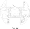
- FIG. 10A illustrates a top view of an embodiment of a button, rubber boot assembly, a light pipe assembly, and a PCB.
- FIG. 10A illustrates a location of cross-section 1000. The location of cross-section 1000 may also be indicative of the location of cross-section 1100 of FIG. 11 and 1200 of FIG. 12 .
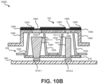
- FIG. 10B illustrates a cross-section 1000 of button 702, light boot assembly 230, light pipe assembly 270, and PCB 255.
- two lighting elements which may be LEDs, are mounted on PCB 255: lighting element 1010-1 and lighting element 1010-2. Lighting element 1010-1, when active, emits light into light pipe 1020 of light pipe assembly 270.
- Lighting element 1010-2 when active, emits light into light pipe 1015 of light pipe assembly 270.
- Light pipes 1020 and 1015 may have different shapes to illuminate different sizes of graphics, icons, text, or numbers on button 702. For instance, light pipe 1020 may have a wider top than light pipe 1015 to accommodate even illumination of a larger graphic on button 702.
- Light pipes 1020 and 1015 may be made from a transparent or translucent material, such as glass or clear plastic. Due to the refraction index between air and the transparent or translucent material of light pipes 1020 and 1015, most light emitted by lighting elements 1010 may be internally reflected within light pipes 1015 and 1020 and emitted from front surfaces 1011-1 and 1011-2.
- Rubber boot 1025 may be opaque and prevent stray light from light pipe 1020 (e.g., light emitted from a side of light pipe 1020) or light from lighting element 1010-1 from inadvertently allowing reflected light to exit the actuator.
- Rubber boot 1030 may also be opaque and prevent stray light from light pipe 1015 (e.g., light emitted from a side of light pipe 1015) or light from lighting element 1010-2 that did not enter light pipe 1015 from inadvertently allowing reflected light to exit the actuator.
- button 702 When button 702 is depressed, light pipes 1020 and 1015 may be unaffected, but rubber boots 1025 and 1030 may be partially compressed or deformed.
- rubber boots 1025 and 1030 While being compressed or deformed, rubber boots 1025 and 1030 may continue to block light from being reflected to an undesired location.
- rubber boots 1025 and 1030 may be formed from some other flexible or semi-flexible material.
- rubber boots 1025 and 1030 may be located at least a distance from button 702 such that when button 702 is depressed, button 702 does not touch rubber boots 1025 or 1030.
- Such an arrangement may permit rubber boots 1025 or 1030 to be formed from a rigid or semi-rigid material, such as plastic or metal.
- Button 702 may include body 1040, which may be formed from an opaque material, such as plastic or metal. Body 1040 may have regions, such as region 1045 and region 1046, that are filled with a translucent or transparent material, such as plastic or glass. Regions 1045 and 1046 can refer, for example, to regions 902 and 901, respectively, of FIG. 9 .
- a coat of opaque paint 1050 which may be black, may be applied. This opaque paint may block light from being emitted through a front of body 1040. A portion of this opaque paint 1050 may be removed, such as via laser etching, to form one or more graphics, icons, letters, or numbers over regions 1045 and 1046.
- the front surface, over the coat of opaque paint 1050 and etched portions, may be coated with semi-transparent paint 1055, which may be gray or some other color. Semi-transparent paint 1055 may allow light to be passed through in regions 1060 where the semi-transparent paint is affixed directly to regions 1045 and 1046.
- cross-section 1000 illustrates two light pipes 1020 and 1015, which are of different shapes, it should be understood that cross-section 1000 is merely an example. In other embodiments, greater or fewer numbers of light pipes may be present. Further, the light pipes may be of the same shape or various other shapes.
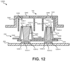
- Light pipe extensions 1230 in combination with a lower surface of light pipes 1015 and 1020, partially enclose lighting elements 1010.
- light pipe extensions 1230-1 and 1230-2 may be part of a single continuous structure that encircles lighting element 1010-1.
- light pipe extensions 1230-3 and 1230-4 may be part of a single continuous structure that encircles lighting element 1010-2.
- light pipe extensions 1230 may touch PCB 255 to increase the collection of light emitted from lighting elements 1010.
- light boot assembly 230 may contact light pipes 1015 and 1020 at an edge of light pipe top surfaces 1240 and 1241.
- rubber boot 1025 may contact light pipe 1020. This arrangement may help prevent light emitted from sides of light pipe 1020 other than top surface 1240 from escaping from the actuator device.
- rubber boot 1030 may contact light pipe 1015. This arrangement may help prevent light emitted from sides of light pipe 1020 other than top surface 1240 from escaping from the actuator device. While two contact points are illustrated for each of light pipes 1015 and 1020, it should be understood that this is due to a cross-section being illustrated in embodiment 1200. It should be understood that rubber boot 1025 may contact and encircle top surface 1240. Similarly, rubber boot 1030 may contact and encircle an edge of top surface 1241.
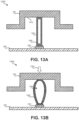
- cavity 1303 may grow in volume by one or more walls of compressible extension 1302 flexing outward. (If cavity 1303 is enclosed, one or more pressure-compensating holes may be present to allow air to enter and leave cavity 1303.) If cavity 1303 is not enclosed, but rather multiple supports make up compressible extension 1302, these supports may flex outward from a relaxed or extended position. When pressure is stopped being applied to button 702, button 702 will move away from PCB 255 and compressible extension 1302 will return to the relaxed or extended position of FIG. 13A . Such embodiments may decrease the manufacturing cost of the actuator by allowing switch 1301 to be mounted in a fixed location on PCB 255, but still help prevent damage to PCB 255 and/or switch 1301 if undue pressure is applied to button 702.
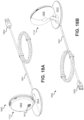
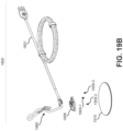
- FIGS. 18A and 18B illustrate an embodiment of stand assembly 1800 that includes stand device 1710 connected with cable 1801 (and without the thermostat (or other smart home device)).
- Cable 1801 may be a universal serial bus (USB) cable (or some other form of cable) that is being used to supply a thermostat that is connected with connector 1810 with power.
- USB connector 1802 may be connected to a power supply or other device that supplies an appropriate direct current voltage.
- Cable 1801 may be permanently connected with base 1815.
- Connector 1810 may be electrically connected to cable 1801 in order to provide a connected thermostat (or other form of smart home device) with power.
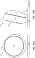
- Stand face 1805 may be a flat or nearly flat surface that allows a thermostat to sit flush on stand device 1710, as illustrated in FIGS 17A and 17B .
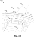
- FIG. 22 illustrates a detailed image of an embodiment 2200 of a connection region between a cable and a base of a stand assembly.
- cable 1810 has an overmold that serves to anchor cable 1801 with base 1815.
- Overmold 2201 may provide strain relief, such that force applied to pulling cable 1801 does not result in force being applied to the wires or contact of cable 1801 where connected with PCB 255. Rather than a hole being present in base 1815 through which cable 1801 passes, slot 2202 is present in base 1815 into which overmold 2201 is inserted prior to baseplate 1910 being attached to base 1815.
- Overmold 2201 may include portion 2210, base edge portion 2211, overmold body 2205, and overmold extensions 2215 (2215-1 and 2215-2).
Landscapes
- Engineering & Computer Science (AREA)
- Microelectronics & Electronic Packaging (AREA)
- Air Conditioning Control Device (AREA)
- Casings For Electric Apparatus (AREA)
Description
- In certain situations, it may be beneficial to have a thermostat located a distance away from a location at which connection to heating, ventilation, and air conditioning (HVAC) control wires are accessible. For instance, HVAC control wires may be run from an HVAC system, behind a wall, and exposed in an inconvenient location, such as within a utility closet. Such a location may not be convenient to be accessed by a user or such a location may not be ideal for accurately sensing the temperature of a region of the structure in which occupants are typically present.
-
EP 3 144 783 A1US 2010/051430 A1 relates to a portable electronic device and a button assembly thereof.KR 2012 0029534 A WO-A-2015/148596 relates to an intelligent thermostat in a smart-home environment which includes a rotating cover fastened to a backplate. - Various embodiments are described related to a smart home device. In some embodiments, a smart home device is described as in claims 1-12.
- In another embodiment, a boiler control system is described as in claim 13.
- A further understanding of the nature and advantages of various embodiments may be realized by reference to the following figures. In the appended figures, similar components or features may have the same reference label. Further, various components of the same type may be distinguished by following the reference label by a dash and a second label that distinguishes among the similar components. If only the first reference label is used in the specification, the description is applicable to any one of the similar components having the same first reference label irrespective of the second reference label.
-
FIG. 1 illustrates an embodiment of a block diagram of an HVAC control system that includes a stand device and an actuator device. -
FIG. 2 illustrates an exploded front view of an embodiment of an actuator device. -
FIG. 3 illustrates an exploded back view of an embodiment of an actuator device. -
FIG. 4A illustrates a front view of an embodiment of a rotatable cover assembly. -
FIG. 4B illustrates a side view of an embodiment of a rotatable cover assembly. -
FIG. 4C illustrates a back view of an embodiment of a rotatable cover assembly. -
FIG. 5 illustrates an exploded back view of an embodiment of a rotatable cover assembly. -
FIG. 6 illustrates a front view of an embodiment of a cover body. -
FIG. 7A illustrates a front view of an embodiment of a chassis assembly. -
FIG. 7B illustrates a back view of an embodiment of a chassis assembly. -
FIG. 7C illustrates a front view of an embodiment of a chassis assembly with an HVAC wiring connector cover in an open position. -
FIG. 8 illustrates a front view of an embodiment of a chassis assembly with a rotatable cover assembly removed. -
FIG. 9 illustrates a front view of an embodiment of an actuator device in which the rotatable cover assembly is attached to the chassis assembly. -
FIG. 10A illustrates a top view of an embodiment of a button, rubber boot assembly, a light pipe assembly, and a PCB. -
FIG. 10B illustrates a cross-section of an embodiment of a button, a rubber boot assembly, a light pipe assembly, and a PCB. -
FIG. 11 illustrates a cross-section of an embodiment of a button, a rubber boot assembly, a light pipe assembly, and a PCB. -
FIG. 12 illustrates a cross-section of an embodiment of a button, a rubber boot assembly, a light pipe assembly, and a PCB. -
FIGS. 13A and 13B illustrate an embodiment of a cross section of a button, a compressible extension, a switch, and a PCB. -
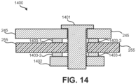
FIG. 14 illustrates an embodiment of a cross-section of a battery contact that is electrically connected with contacts on a PCB. -
FIG. 15A illustrates a front view of an embodiment of a mounting plate. -
FIG. 15B illustrates a back view of an embodiment of a mounting plate. -
FIG. 16A illustrates a front view of an embodiment of a chassis assembly mounted on a mounting plate. -
FIG. 16B illustrates a back view of an embodiment of a chassis assembly mounted on a mounting plate. -
FIG. 17A illustrates a front view of an embodiment of a thermostat attached to a stand device. -
FIG. 17B illustrates a side view of an embodiment of a thermostat attached to a stand device. -
FIG. 18A illustrates a front view of an embodiment of a stand device connected with a power cable. -
FIG. 18B illustrates a back view of an embodiment of a stand device connected with a power cable. -
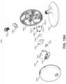
FIGS. 19A and19B , collectively, illustrate a front view of an embodiment of a stand assembly. -
FIG. 20 illustrates an embodiment of a stand assembly with a stand face removed. -
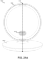
FIG. 21A illustrates an embodiment of a stand assembly. -
FIG. 21B illustrates a cross section of an embodiment of the stand assembly. -
FIG. 22 illustrates a detailed image of an embodiment of a connection region between a cable and a base of a stand assembly. - An actuator device (also referred to as an "actuator") may be connected with control wires. Such control wires may control operation of various components, such as: a furnace; a boiler; a fan; an air conditioner; and/or a multi-stage heating or cooling system. The actuator may open and close circuits in order to control operation of components of the HVAC system. Due to the actuator being directly connected with control wires, the actuator may be located in a hidden, concealed, or inconvenient location, such as in a utility closet, where the HVAC control wires are exposed. A user may have a thermostat and a movable stand device (also referred to as a "stand") that can be connected to a power source near a location where the user desires the thermostat to be located. The user may typically have the thermostat located in a convenient location in a room frequently used by occupants of the structure. The stand is configured to connect with a thermostat and provide the thermostat with power and, possibly, temperature measurements. The thermostat wirelessly communicates with the actuator device in order to control the components of the HVAC system. Thus, the actuator can be directly connected to the control wires and the thermostat can be conveniently located to ensure that the temperature of a desired location is monitored accurately and to enable a user to easily access controls to control the HVAC. The thermostat may receive and implement temperature set-points provided by a user. The thermostat may further learn and/or receive a setpoint schedule to be implemented daily or on certain days of the week. The thermostat may communicate with a remote cloud-based server to provide users with various services via end-user computerized devices, such as a smartphone, desktop, or tablet computer. Although the above has referred to an actuator for use in a HVAC system, this aspect and the other features described herein are not limited to HVAC systems and may be applied to other control systems that may be installed in a home, office, or other location, such as a door entry system, an alarm system, an irrigation system or other similar control systems. Generally the actuator device is configured to control functions of the control system and may be located where the control wires for the control system are exposed. In an example arrangement, the system may additional comprises a remote device, such as a remote control device or a remote sensor or a remote input device, which remote device may include a door bell, camera, temperature sensor, smoke detector, carbon monoxide detectors, home assistants or other similar devices may located in a convenient location (e.g. in a room, within a building, outside of a building, on an entry way) and may wirelessly communicate with the actuator device in order to control the components of the control system. In some implementations, the remote device may be connected to a stand which is configured to provide power to the remote device. Thus, the actuator can be directly connected to the control wires whilst the remote device can be conveniently located to enable a user to easily access controls to control the control system via the actuator.
- Embodiments detailed herein are focused on various aspects of the actuator and stand. Such aspects can improve the functionality, aesthetics, sizing characteristics (e.g., allow the device to be thinner or smaller), and/or manufacturability of the actuator and/or the stand. It is to be appreciated that while one or more embodiments are described further herein in the context of a typical HVAC system used in a residential home, such as a single-family residential home, the scope of the present teachings is defined by the claims. More generally, intelligent thermostat systems according to one or more of the embodiments are applicable for a wide variety of enclosures having one or more HVAC systems including, without limitation, duplexes, townhomes, multi-unit apartment buildings, hotels, retail stores, office buildings, and industrial buildings. Further, it is to be appreciated that while the terms user, customer, installer, homeowner, occupant, guest, tenant, landlord, repair person, and/or the like may be used to refer to the person or persons who are interacting with the thermostat or other device or user interface in the context of one or more scenarios described herein, these references are by no means to be considered as limiting the scope of the present teachings as defined by the claims with respect to the person or persons who are performing such actions.
- It is to be appreciated that "smart home environments" may refer to smart environments for homes such as a single-family house, but the scope of the present teachings is defined by the claims, the present teachings being likewise applicable, without limitation, to duplexes, townhomes, multi-unit apartment buildings, hotels, retail stores, office buildings, industrial buildings, and more generally any living space or work space having one or more smart hazard detectors.
- While embodiments detailed herein are focused on actuators or thermostats connected to stands, it should be understood that the embodiments detailed herein may be applicable to other smart home devices and/or sensor devices. For instance, aspects of the detailed actuators and/or stands may be applied to thermostats, smoke detectors, carbon monoxide detectors, doorbells, home assistants, video cameras, remote temperature sensors, or other smart home devices that may be installed in a home, office, or other location. A smart home device is a device operable as a control device and/or a sensor device and/or a user input device. Thus, the smart home device may be an actuator as discussed herein or a thermostat as discussed herein. The smart home device may also include, smoke detectors, carbon monoxide detectors, doorbells, home assistants, video cameras, remote temperature sensors, or other similar devices.
-
FIG. 1 illustrates an embodiment of a block diagram of anHVAC control system 100 that includes a stand and an actuator. Embodiments detailed in this document can represent components ofHVAC control system 100. However, as discussed above, one or more of the features described herein may be implemented in other control systems and it is not intended to limit the features described below only to HVAC control systems.HVAC control system 100 may include:actuator device 110; mountingplate 120;HVAC system 130;thermostat 140; and standdevice 150.Actuator device 110 may be attached to a mountingplate 120. Mountingplate 120 may facilitateactuator device 110 being attached to a surface (e.g., a wall) and allowing HVAC control wires to be routed into a back ofactuator device 110. For instance, HVAC control wires may be mounted on a surface of a wall. Mountingplate 120 may allowactuator device 110 to be secured to the surface of the wall while allowing HVAC control wires to be passed through a rear surface ofactuator device 110.Actuator device 110 may be connected via multiple HVAC control wires toHVAC system 130. -
Actuator device 110 may include:display 111,user interface 112,processing system 113,wireless interface 114, andcontrol interface 115.Display 111, which may include one or more LEDs or other forms of lighting elements, may present information to a user.Display 111 may include a "dead front" display. A "dead front" display is a display that appears to have a blank display surface (e.g. that is difficult to identify as a display) when the one or more lighting elements are inactive. When active, the lighting elements light the display to make one or more images, such as symbols, text, particular region on the display, visible to the user on the display surface,.User interface 112 may include one or more buttons or other forms of user input devices that allow a user to provide input directly toactuator device 110. For instance,user interface 112 may be used to engage one or more components ofHVAC system 130 without a user needing to interact withthermostat 140.Processing system 113 may include one or more processors that receive and send information viawireless interface 114 tothermostat 140.Processing system 113 may receive input fromuser interface 112, output information that is presented viadisplay 111, and control actuation of HVAC components viacontrol interface 115.Wireless interface 114 may use one or more wireless communication protocols, such as: Wi-Fi® (IEEE 802.11), IEEE 802.15.4, Bluetooth®, Z-Wave®, ZigBee®, Thread®, or some other wireless communication protocol to communicate withthermostat 140.Control interface 115 may open and close circuits that include HVAC control wires based on instructions fromprocessing system 113 to controlHVAC system 130. -
Thermostat 140 may wirelessly communicate withactuator device 110.Thermostat 140 may transmit instructions, such as via the use of one of the previously-detailed wireless communication protocols, to instructactuator device 110 to activate or deactivate one or more components ofHVAC system 130.Thermostat 140 may be removably coupled withstand device 150.Thermostat 140 may communicate via a wireless network (e.g., a Wi-Fi WLAN) withInternet 141. ViaInternet 141,thermostat 140 may transmit data to and receive data from cloud-basedserver system 142. Cloud-basedserver system 142 may maintain a user account that stores data related tothermostat 140 and may permit a user to remotely control and/or view data related tothermostat 140. For example, a user may communicate with cloud-basedserver system 142 to modify a setpoint schedule implemented bythermostat 140 or may provide a real time setpoint that is used to immediately controlHVAC system 130 by thermostat 140 (via actuator device 110). -
Stand device 150 may be placed on a surface and may have apower system 151 that powersthermostat 140.Power system 151 may be connected with a power outlet (e.g., 120 V, 230 V) and may output a constant voltage tothermostat 140.Stand device 150 may have one or more on-board sensors, such as temperature and/orhumidity sensor 152, that provides temperature and/or humidity measurements tothermostat 140. - Further details regarding
actuator device 110, mountingplate 120, and standdevice 150 are provided in relation toFIGS. 2 - 22 .FIG. 2 illustrates an exploded view of a top of anactuator 200.Actuator 200 can represent an embodiment ofactuator device 110 ofFIG. 1 . The following describes an actuator for controlling a HVAC system but, as discussed above, it is not intended to limit the features described herein only to an actuator for a HVAC control system. It will be appreciated that one or more features described herein may be used in actuators for controlling other control systems or in other smart home devices. In the following, the smart home device comprisesactuator 200 which comprises a chassis assembly that defines one or more compartments and which comprises a plurality of cover fasteners. Theactuator 200 further comprises a rotatable cover assembly configured to be removably attached with the plurality of cover fasteners to the chassis assembly to at least partially cover a front of the chassis assembly. While the rotatable cover assembly is removably attached with the plurality of cover fasteners, the rotatable cover assembly is configured to be rotatable with respect to the chassis assembly and while the rotatable cover is removably attached with the plurality of cover fasteners, the rotatable cover assembly is configured to block access to the one or more compartments defined by the chassis assembly. The one or more compartments of the chassis assembly are configured to support components of theactuator 200. The components of theactuator 200 may include one or more of::chassis 210; display (not shown inFIG. 2 );wiring connector cover 215; cover fastener assemblies or fasteners 220 (220-1, 220-2) (hereinafter referred to as cover fastener assemblies) for removably attaching therotatable cover assembly 205 to the chassis assembly;light boot assembly 230;battery contact 240;battery spring 241,spring cap 242;battery spring 243;spring cap 244,battery contact 245;support 250; printed circuit board (PCB) 255;backplate 260;batteries 265; light pipe assembly 270 (which can include multiple light pipes and the structure to which the light pipes are attached);battery holder tab 701;button 702; and coverleash 704.Rotatable cover assembly 205 is designed to be facing away from a surface to whichbackplate 260 is mounted. As such,rotatable cover assembly 205, when removably attached withchassis 210 of chassis assembly, may be the component ofactuator 200 most visible to a user.Rotatable cover assembly 205 may be removable by a user, such as by pulling edges ofrotatable cover assembly 205 to release the rotatable cover assembly from the plurality of cover fastener assemblies. Removingrotatable cover assembly 205 can allow a user to access wiring connectors and/or a battery compartment ofchassis 210. In other words, with the rotatable cover assembly being removably attached to the chassis assembly, a user can easily access the compartments of the chassis assembly to enable a user to more easily install the smart home device (e.g. make the wiring connections to the device), replace batteries and/or check and/or fix wiring connections once the smart home device has been installed. Further, byrotatable cover assembly 205 being rotatable, a user can rotaterotatable cover assembly 205 to a desired orientation, which may be desirable for aesthetic reasons.PCB 255 may have components such as a wireless interface (e.g., wireless interface 114) and processing system (e.g., processing system 113) mounted to it. -
FIG. 3 illustrates an exploded view of a bottom ofactuator 200.FIG. 3 illustrates a back side of each component ofactuator 200 as compared to the front side illustrated inFIG. 2 . -
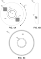
FIG. 4A illustrates a front view of an embodiment of arotatable cover assembly 400.FIG. 4B illustrates a side view of an embodiment of therotatable cover assembly 400.FIG. 4C illustrates a back view of an embodiment of arotatable cover assembly 400.Rotatable cover assembly 400 can represent an embodiment ofrotatable cover assembly 205. Rotatable cover assembly comprises acover body 403. Therotatable cover assembly 400 may be circular.FIG. 4A , which represents a top or front surface of rotatable cover assembly 400 (e.g. front surface of cover body 403), may be fully or partially covered in a fabric, cloth, or screening. For instance, a knit fabric may be used as an outer layer ofrotatable cover assembly 400. It should be understood that this fabric or screening pattern may be stretched over the entirety of the front or top surface illustrated inFIG. 4A .Fabric 401, which may cover an entire front surface ofrotatable cover assembly 400, can have a visible pattern or texture. This visible pattern or texture may be more aesthetically pleasing to persons if aligned in a particular orientation. For example, if the visible pattern exhibits a series of parallel lines or a grid, a person my desire to have these lines or the grid aligned either parallel or perpendicular to features of a region in which actuator 200 is installed. For example, such lines or a grid may be desired to be parallel to a joint where walls meet, the ceiling meets a wall, or a wall meets the floor. Further, the fabric allows for a user to easily grip therotatable cover assembly 400 and removerotatable cover assembly 400 for access to internal components.Fabric 401 may exhibit an amount of stretch, allowing it to be stretched over a front surface ofrotatable cover assembly 400.Fabric 401 may be made of natural, synthetic, or a blend of natural and synthetic fibers.Fabric 401 may be treated in order to change or improve various characteristics offabric 401. For instance,fabric 401 may be treated with an anti-mold compound to discourage the growth of mold onfabric 401, especially if the actuator is installed in a moist environment. In other embodiments, rather than a fabric being used, some other material may be used as a front or top surface ofrotatable cover assembly 400, such as a metallic or plastic screening. - Due to
fabric 401 having a visible pattern and/or texture, whenrotatable cover assembly 400 is installed on an actuator, it may be desirable for aesthetics forrotatable cover assembly 400 to be in a particular alignment -- for example, such that the pattern offabric 401 is parallel or perpendicular to a nearby floor, wall, and/or ceiling.Rotatable cover assembly 400 may be infinitely rotatable in a clockwise and counterclockwise rotation, such as illustrated byarrow 410.Rotatable cover assembly 400 may have no indexed locations, aroundchassis 210. Afterrotatable cover assembly 400 has been removably coupled withchassis 210, a user may rotaterotatable cover assembly 400 either clockwise or counterclockwise to a desired orientation. Once released, friction betweenrotatable cover assembly 400 and cover fastener assemblies 220 may hold rotatable cover assembly in the desired orientation. - In a center of
rotatable cover assembly 400, anopen region 402 may be defined. When attached withchassis 210 of chassis assembly, a display and/or button supported in the chassis assembly may be visible and/or accessible through theopen region 402. Thus, therotatable cover assembly 400 may cover a front of the chassis assembly except for an area of the chassis assembly corresponding to theopen region 402.Fabric 401 may extend along a curvature ofrotatable cover assembly 400 onto each side ofrotatable cover assembly 400, as illustrated inFIG. 4B . Each side ofrotatable cover assembly 400 may match the representation ofFIG. 4B . - In
FIG. 4C , a bottom ofrotatable cover assembly 400 is illustrated. A bottom surface ofcover body 403 may not be covered with fabric or screening and may instead be exposed plastic.Cover body 403 is rigid or semi-rigid such thatfabric 401 conforms to an outer surface ofcover body 403.Inner ring 405 may be used to fastenfabric 401 as part ofrotatable cover assembly 400 in a stretched state. In some embodiments,fabric 401 may be glued or otherwise affixed to coverbody 403. In such embodiments, one or more rings (e.g., inner ring 405) may be a stick-on label that serves to hide an edge offabric 401 from viewing by a user. The use of such a ring may be primarily for aesthetic reasons. At least some elasticity may be incorporated as part offabric 401 such that iffabric 401 is stretched or otherwise displaced by a user,fabric 401 will return to its original position when released.Inner ring 405 may be attached to coverbody 403 and may securefabric 401 to coverbody 403 such that edges offabric 401 are concealed. In some embodiments, an outer ring may be present. In other embodiments,fabric 401 may be affixed, such as using glue, directly to coverbody 403 around an inner edge ofcover body 403. Also alternatively, rather thaninner ring 405 being present,fabric 401 may be affixed, such as by using glue directly, to coverbody 403 around an edge ofcover body 403 present on a bottom surface ofcover body 403 whereinner ring 405 is illustrated as being present. - Referring back to
FIG. 4A , beneathfabric 401, an adhesive may be present, such as inregion 412, to affixfabric 401 to a front surface ofcover body 403. The adhesive used may be a pressure sensitive adhesive (PSA) that may be applied in the form of a doubled-sided pressure-sensitive tape. However, despite being a PSA, the PSA may be heated when applied between the front surface ofcover body 403 andfabric 401. By heating the PSA, certain properties typical to a heat sensitive adhesive (HSA) may be realized. For example, some of the PSA may be wicked a distance into the knit of the fabric due to a capillary effect. Such wicking may result in better adhesion betweenfabric 401 and a front surface ofcover body 403. While in some embodiments ring-shapedregion 412 is where the PSA is applied and heated, it should be understood that in other embodiments, the PSA may be applied and heated in other or multiple locations. For instance, the PSA may be applied and heated underinner ring 405 on a back surface ofcover body 403. -
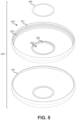
FIG. 5 illustrates an exploded bottom view ofrotatable cover assembly 400. In some embodiments,inner ring 405 may be present, but not an outer ring.Rotatable cover assembly 400 may include:inner ring 405;cover body 403; andfabric 401.Fabric 401 may obtain the shape illustrated inFIG. 5 by being stretched over a top or front surface ofcover body 403.Fabric 401 may be fastened or affixed (e.g., glued) toinner edge 501. After being fastened or affixed toinner edge 501,fabric 401 may be trimmed along the fastened or affixed edge such that a roughly even edge with minimal or limited fraying is present.Fabric 401 may further be stretched throughopen region 402 and fastened toinner ring surface 502.Inner ring 405 may be fastened or affixed (e.g., glued) toinner ring surface 502 such that an edge offabric 401 is secured byinner ring 405 toinner ring surface 502 and hidden from view. - Present on an inner surface of
cover body 403 may becircular track 503.Circular track 503 may define at least two lips that continuously extend along an inner surface ofcover body 403 and may interface with cover fastener assemblies 220. Cover fastener assemblies 220 may each include a protrusion that slides within the lips ofcircular track 503. The protrusions of the cover fastener assemblies and the lips of thecircular track 503 are configured to co-operate so as to allowrotatable cover assembly 400 to be pushed ontochassis assembly 700 in any rotational orientation in whichcircular track 503 is coaxial with the chassis assembly. As such, a user, when desiring to attachrotatable cover assembly 400 to the chassis assembly does not need to attempt to align protrusions of the cover fastener assemblies with any particular part ofcircular track 503. Further, the protrusions of the cover fastener assemblies and the lips of thecircular track 503 are configured to co-operate so as to facilitate the rotation of the rotatable cover assembly with respect to the chassis assembly when the rotatable cover assembly is attached to the chassis assembly whilst enabling easy removal by a user of the rotatable cover assembly from the chassis assembly regardless of the rotational orientation ofrotatable cover assembly 400 with respect tochassis assembly 700. Friction can be present between cover fastener assemblies 220 andcircular track 503 such that when a user is not twistingrotatable cover assembly 400 with respect tochassis 210,rotatable cover assembly 400 orientation remains static. -
FIG. 6 illustrates an embodiment ofcover body 403.Cover body 403 may be formed or made from a rigid or semi-rigid material, such as plastic or metal. In some embodiments,cover body 403 is injection molded. A top surface ofcover body 403 may have a texture, such as indicated by raisedprotrusions 602 in magnifiedregion 601. In some embodiments, raisedprotrusions 602 are rectangular pyramids, triangular pyramids, or some other raised pyramidal structure. In some embodiments, raisedprotrusions 602 may be randomly chemically etched. Raisedprotrusions 602 may cover an outer or top surface ofcover body 403. Raisedprotrusions 602 may serve multiple purposes. Whenfabric 401 is stretched and wrapped over the top surface ofcover body 403, raisedprotrusions 602 may provide friction and help keepfabric 401 in place. For instance, if a user applies lateral pressure tofabric 401 whilefabric 401 is wrapped over the top surface ofcover body 403, raisedprotrusions 602 may help preventfabric 401 from further stretching and/or bunching. Additionally or alternatively, raised protrusions may increase or otherwise alter the textural feel offabric 401 whenfabric 401 is stretched and wrapped over the top surface ofcover body 403. - Raised
protrusions 602 represent one possible embodiment of a texture that may be present on a top or front surface ofcover body 403. In other embodiments, various forms of texture may be formed as part of the top or front surface ofcover body 403 that: 1) help holdfabric 401 in place over a top or front surface ofcover body 403; and/or 2) alter the textural feel offabric 401 when wrapped over the top or front surface ofcover body 403. On a bottom or back side ofcover body 403, raisedprotrusions 602 may not be present and the bottom or back surface may be smooth. -
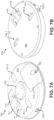
FIG. 7A illustrates a top (or front) view of an embodiment ofchassis assembly 700.FIG. 7B illustrates a bottom (or back) view of an embodiment ofchassis assembly 700. The following describes a chassis assembly of an actuator for controlling a HVAC system but, as discussed above, it is not intended to limit the features described herein only to an actuator for a HVAC control system. It will be appreciated that one or more features described herein may be used in a chassis assembly of an actuator for controlling other control systems or of another smart home device.Chassis assembly 700 may includechassis 210,wiring connector cover 215, cover fastener assemblies 220,button 702, andbackplate 260.wiring connector cover 215 may be a leashed cover. Whenrotatable cover assembly 400 is removed fromchassis 210,battery compartment 710 andwiring connector cover 215 may be visible and accessible. When unfastened (e.g., whenscrew 705 is unscrewed),wiring connector cover 215 may be hung in an open position viacover leash 704. This may allow a user to access terminals present within an wiring compartment to allow control wires, such as HVAC control wires, to be attached and detached. Control wires may be routed throughrear opening 703 into the wiring compartment that is covered from a front by wiringconnector cover 215. By virtue ofcover leash 704 being used to permanently securewiring connector cover 215 tochassis 210, the loss ofwiring connector cover 215 may be prevented.Button 702 may function as both a display and a user-pressable button that allows direct control of a control system, such as a HVAC system, atactuator 200 by a user. For instance, a user may pressbutton 702 to manually activate one or more HVAC systems (e.g., a boiler). - A protruding slider of cover fastener assemblies 220 may protrude through
chassis 210. Cover fastener assemblies 220 may be fastened tochassis 210 and may be made of a semi rigid material that can flex inward when pressure is applied to a protruding slider of each cover fastener assembly. Pressure applied to a protruding slider of cover fastener assemblies 220 may cause the protruding slider to at least partially retract to withinchassis 210. Each protruding slider may be tapered on a top and bottom side to allow the slider to retract whenrotatable cover assembly 205 is pushed onto or pulled off ofchassis assembly 700. The protruding sliders of cover fastener assemblies 220 may rest in a fully or partially extended state withincircular track 503 ofcover body 403 whenrotatable cover assembly 400 is attached withchassis 210. The protruding sliders of cover fastener assemblies 220 can allow forrotatable cover assembly 400 to be rotated and oriented into any desirable orientation, such that a texture or grain offabric 401 is aligned with objects or surfaces in the environment of the actuator. Whencover body 403 is pulled away fromchassis 210 or whencover body 403 is pushed ontochassis 210, the protruding sliders of cover fastener assemblies 220 may retract to allow for coupling and decoupling. While two cover fastener assemblies are illustrated as present onchassis assembly 700, it should be understood that fewer or greater numbers of cover fastener assemblies 220 may be present in other embodiments. - Fastener pass-throughs 707 (707-1 and 707-2) may allow for fasteners to be installed through a front of
chassis 210 to attachbackplate 260 to a surface, such as a wall. By virtue ofchassis 210 being fastened tobackplate 260,chassis 210 is also fastened to the surface. Fasteners may attach with a surface through fastener openings 706 (706-1, 706-2). Fastener pass-throughs 707 may allow for a screw driver or other installation tool to be used to attach fasteners, such as screws, throughchassis 210 tobackplate 260.Backplate 260 may have a flat exterior surface to permitbackplate 260 to be attached flush to a surface, such as a wall. Such attachment may occur over a location where control wires, such as HVAC control wires, pass through an opening in a wall. - Various compartments may be defined by
chassis 210 ofchassis assembly 700, includingbattery compartment 710 and/orcontrol wire compartment 725.Battery compartment 710 may be used to house one or more batteries, such asbatteries 265. When batteries are installed inbattery compartment 710 androtatable cover assembly 400 is removed fromchassis assembly 700,batteries 265 may be partially visible.Battery holder tab 701 may help keep batteries in position withinbattery compartment 710 such that the batteries properly contactspring cap 242,spring cap 244,battery contact 240, andbattery contact 245 whenrotatable cover assembly 205 is attached withchassis assembly 700. That is, a back surface ofbattery holder tab 701 may be made of a flexible material and may be curved to roughly match a curvature of cylindrical batteries that are to be installed inbattery compartment 710; the inner surface ofrotatable cover assembly 205 may keepbattery holder tab 701 pressed against the batteries and in a proper position withinbattery compartment 710.Battery holder tab 701 may be connected to aflexible ribbon leash 711.Ribbon leash 711 may serve multiple purposes. First,ribbon leash 711 may help preventbattery holder tab 701 from being lost bybattery holder tab 701 being permanently attached tobattery holder tab 701 and tochassis 210. Whenbattery holder tab 701 is pulled by a user,ribbon leash 711 may push batteries out ofbattery compartment 710 due toribbon leash 711 residing underbatteries 265 whenbatteries 265 are installed inbattery compartment 710. Therefore,battery holder tab 701 and attachedbattery ribbon leash 711 may function together as a single structure to both: 1) hold batteries in place withinbattery compartment 710; and 2) help remove batteries frombattery compartment 710. It should be understood thatbattery holder tab 701 andribbon leash 711 may be adapted for use with fewer or greater numbers of batteries. -
FIG. 7C illustrates a front view of an embodiment ofchassis assembly 700 withwiring connector cover 215 in an open position. When wiringconnector cover 215 is open, terminals 720 (e.g., 720-1, 720-2, 720-3, 720-4, and 720-5) may be accessible. control wires, such as HVAC control wires, may entercontrol wire compartment 725 throughrear opening 703. Whenchassis assembly 700 is mounted to a wall,wiring connector cover 215 can be hung in an open position. In such a position, it may be possible to attachrotatable cover assembly 205 tochassis assembly 700. -
Cover leash 704 may be rubber or some other flexible or semi-rigid material. When wiringconnector cover 215 is closed, access to terminals 720 is prevented and coverleash 704 may be stored withincontrol wire compartment 725. -
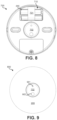
FIG. 8 illustrates a front view ofchassis assembly 700 withrotatable cover assembly 205 removed. As can be seen,batteries 265, when installed, reside belowbattery holder tab 701, but aboveribbon leash 711. Therefore, whenbattery holder tab 701 is pulled away fromchassis 210,ribbon leash 711 will extend away frombattery compartment 710 and will pushbatteries 265 frombattery compartment 710. - Dead
front display 702 may function as a display and as a button (button 702).FIG. 9 illustrates a front view ofactuator 200 in whichrotatable cover assembly 205 is removably attached withchassis assembly 700. Whenrotatable cover assembly 205 is attached withchassis assembly 700, deadfront display 702 remains exposed and visible. Deadfront display 702 may appear to have a blank display surface when no internal light behind the dead front display surface is illuminated.Region 901 orregion 902 may be at least partially illuminated from withinchassis assembly 700 when one or both of the internal lights are illuminated. Various graphics, numbers, or letters may be illuminated by etching such graphics, numbers, or letters into a layer ofregions front display 702. The dead front display surface may be movable with respect to the opening in therotatable cover assembly 205. A user may press deadfront display 702 such that deadfront display 702 depresses a distance and functions as a button. -
FIG. 10A illustrates a top view of an embodiment of a button, rubber boot assembly, a light pipe assembly, and a PCB.FIG. 10A illustrates a location ofcross-section 1000. The location ofcross-section 1000 may also be indicative of the location ofcross-section 1100 ofFIG. 11 and 1200 ofFIG. 12 .FIG. 10B illustrates across-section 1000 ofbutton 702,light boot assembly 230,light pipe assembly 270, andPCB 255. Incross-section 1000, two lighting elements, which may be LEDs, are mounted on PCB 255: lighting element 1010-1 and lighting element 1010-2. Lighting element 1010-1, when active, emits light intolight pipe 1020 oflight pipe assembly 270. Lighting element 1010-2, when active, emits light intolight pipe 1015 oflight pipe assembly 270.Light pipes button 702. For instance,light pipe 1020 may have a wider top thanlight pipe 1015 to accommodate even illumination of a larger graphic onbutton 702.Light pipes light pipes light pipes -
Rubber boot 1025 may be opaque and prevent stray light from light pipe 1020 (e.g., light emitted from a side of light pipe 1020) or light from lighting element 1010-1 from inadvertently allowing reflected light to exit the actuator.Rubber boot 1030 may also be opaque and prevent stray light from light pipe 1015 (e.g., light emitted from a side of light pipe 1015) or light from lighting element 1010-2 that did not enterlight pipe 1015 from inadvertently allowing reflected light to exit the actuator. Whenbutton 702 is depressed,light pipes rubber boots rubber boots rubber boots rubber boots button 702 such that whenbutton 702 is depressed,button 702 does not touchrubber boots rubber boots - Light from lighting element 1010-1 may primarily be emitted through front surface 1011-1. Similarly, light from lighting element 1010-2 may primarily be emitted through front surface 1011-2.
Button 702 may includebody 1040, which may be formed from an opaque material, such as plastic or metal.Body 1040 may have regions, such asregion 1045 andregion 1046, that are filled with a translucent or transparent material, such as plastic or glass.Regions regions FIG. 9 . - On a front surface of
body 1040, a coat ofopaque paint 1050, which may be black, may be applied. This opaque paint may block light from being emitted through a front ofbody 1040. A portion of thisopaque paint 1050 may be removed, such as via laser etching, to form one or more graphics, icons, letters, or numbers overregions opaque paint 1050 and etched portions, may be coated withsemi-transparent paint 1055, which may be gray or some other color.Semi-transparent paint 1055 may allow light to be passed through inregions 1060 where the semi-transparent paint is affixed directly toregions regions button 702 may appear blank or a "dead" front. Due to removal having been performed to some portion ofopaque paint 1050,regions 1060 may appear slightly depressed or inset from a front surface ofbutton 702. - While
cross-section 1000 illustrates twolight pipes cross-section 1000 is merely an example. In other embodiments, greater or fewer numbers of light pipes may be present. Further, the light pipes may be of the same shape or various other shapes. -
FIG. 11 illustrates across-section 1100 ofbutton 702,light boot assembly 230,light pipe assembly 270, andPCB 255 as indicated by theline 1001 inFIG. 10A . The embodiment ofFIG. 11 functions differently in that a dead front ofbutton 702 is achieved in a different way than inFIG. 10 . InFIG. 11 ,transparent inserts body 1040 such that on atop surface 1041 ofbody 1040, the inserts are exposed and shaped to match the graphic, icon, letters, or numbers that are to be displayed when the corresponding lighting element is lit. In some embodiments, there is a paint layer, which may be black, atoptransparent inserts body 1040, along with the top surfaces oftransparent inserts button 702 may be flat. When lighting elements 1010 are not emitting, top surface 1130 may appear blank (e.g., a "dead front"). When lighting element 1010-1 is emitting light, the shape formed ontop surface 1041 may be illuminated through semi-transparent paint 1120. The embodiment ofFIG. 11 may require fewer manufacturing steps to manufacture than the embodiment ofFIG. 10 since no etching is needed. In some embodiments,rubber boot 1025 andrubber boot 1030 may not contactlight pipes light pipes light pipes light pipes rubber boot 1025 orrubber boot 1030 contacted a side oflight pipes -
FIG. 12 illustrates anembodiment 1200 of a cross-section ofbutton 702,light boot assembly 230,light pipe assembly 270, andPCB 255 as indicated by theline 1001 inFIG. 10A .Embodiment 1200 may be used in conjunction with the "dead-front" embodiments detailed in relation toFIGS. 11 and12 or may be used separately.Embodiment 1200 includes features that make it more difficult for stray light from lighting element 1010 to exit the actuator device, other than through the corresponding transparent inserts. Inembodiment 1200, light pipe extensions 1230 (1230-1, 1230-2, 1230-3, and 1230-4) extend downward fromlight pipe assembly 270 and serve to capture additional light from lighting elements 1010. Light pipe extensions 1230, in combination with a lower surface oflight pipes PCB 255 to increase the collection of light emitted from lighting elements 1010. - Additionally or alternatively,
light boot assembly 230 may contactlight pipes pipe top surfaces rubber boot 1025 may contactlight pipe 1020. This arrangement may help prevent light emitted from sides oflight pipe 1020 other thantop surface 1240 from escaping from the actuator device. Similarly, at contact points 1210-3 and 1210-4,rubber boot 1030 may contactlight pipe 1015. This arrangement may help prevent light emitted from sides oflight pipe 1020 other thantop surface 1240 from escaping from the actuator device. While two contact points are illustrated for each oflight pipes embodiment 1200. It should be understood thatrubber boot 1025 may contact and encircletop surface 1240. Similarly,rubber boot 1030 may contact and encircle an edge oftop surface 1241. - Additionally or alternatively, light containment extensions 1220 may extend downward from
button 702. Light containment extensions 1220 may prevent light emitted fromtop surfaces transparent regions body 1040. Light containment extensions 1220 may extend frombutton 702 towardsPCB 255 and may form partially-enclosedcavities Light pipes cavities cavities top surfaces button 702 is fully depressed,button 702 or light containment extensions 1220 do not contactPCB 255,light boot assembly 230 orlight pipe assembly 270. It should be understood that light containment extensions 1220-1 and 1220-2 may be part of a continuous light containment extension that formscavity 1250. Similarly, it should be understood that light containment extensions 1220-3 and 1220-4 may be part of a continuous light containment extension that formscavity 1251. -
FIGS. 13A and 13B illustrate an embodiment ofcross section 1300 ofbutton 702,compressible extension 1302,switch 1301, andPCB 255.Cross section 1300 can represent an embodiment of a cross section in the location of cross section 1000 (without any light pipes or rubber boots illustrated for simplicity). In the embodiment ofcross section 1300,button 702 can be pushed by a user. Whenbutton 702 is depressed,button 702 travels towardsPCB 255; however,PCB 255 remains in a fixed location. As such, when pushed,button 702 becomes closer toPCB 255.Switch 1301 may be soldered (surface mount, through-mount) or otherwise affixed toPCB 255. Whenbutton 702 is pushed,switch 1301 may be actuated such that one or more components on PCB 255 (e.g., a processor) can determine thatbutton 702 has been pushed. -
Compressible extension 1302 may extend from abottom surface 1310 ofbutton 702 to switch 1301.Compressible extension 1302 may be hollow, such that an outer wall encloses acavity 1303 filled with air. In other embodiments, multiple flexible supports may extend frombottom surface 1310 to switch 1301 such thatcavity 1303 is not enclosed, but is rather an open region.Compressible extension 1302 may be made from a flexible or semi-rigid material that is rigid enough that whenbutton 702 is depressed,compressible extension 1302 exerts sufficient force to actuateswitch 1301. For example,compressible extension 1302 may be made from rubber or plastic. Whenswitch 1301 has been actuated butbutton 702 is further depressed,compressible extension 1302 may flex. This flexing may prevent excessive force from being exerted ontoswitch 1301 and/orPCB 255, which could damage various components (e.g., breakswitch 1301, bend PCB 255). - A switch may be damaged by impact force on the button surface. The structures of
FIGS. 13A and 13B prevent damage by helping to absorb impact energy that would cause damage to switch 1301 without being flexible at normal use forces. Such an arrangement can prevents the button from feeling "mushy" (e.g., can help maintain a feeling of a tactile click). As shown inFIG. 13A , whenbutton 702 is not pushed or insufficient pressure is exerted,compressible extension 1302 is in a fully extended state. As shown inFIG. 13B , when sufficient pressure is exerted on button 702 (as indicated by arrow 1320),switch 1301 is actuated andcompressible extension 1302 flexes outward to prevent excessive force from being transferred to switch 1301 andPCB 255. In some embodiments,cavity 1303 may grow in volume by one or more walls ofcompressible extension 1302 flexing outward. (Ifcavity 1303 is enclosed, one or more pressure-compensating holes may be present to allow air to enter and leavecavity 1303.) Ifcavity 1303 is not enclosed, but rather multiple supports make upcompressible extension 1302, these supports may flex outward from a relaxed or extended position. When pressure is stopped being applied tobutton 702,button 702 will move away fromPCB 255 andcompressible extension 1302 will return to the relaxed or extended position ofFIG. 13A . Such embodiments may decrease the manufacturing cost of the actuator by allowingswitch 1301 to be mounted in a fixed location onPCB 255, but still help prevent damage toPCB 255 and/orswitch 1301 if undue pressure is applied tobutton 702. - Referring to
FIG. 11 , whenbutton 702 is pressed, sufficient distance betweenlight pipes button 702 may be present such thatbutton 702 does not contactlight pipes button 702 andrubber boots rubber boots rubber boots button 702 is depressed. While compressed or deformed,rubber boots light pipes -
FIG. 14 illustrates anembodiment 1400 of a cross-section of a battery contact that is electrically connected with contacts onPCB 255. Inembodiment 1400,battery contact 245, which may contact a terminal of a battery, is illustrated. In order to firmly affixbattery contact 245 toPCB 255, an arrangement that will be resilient enough to withstand multiple impacts may be useful. For instance, a soldered connection may be insufficient to protect a connection betweenbattery contact 245 and an electrical contact onPCB 255 if the actuator device has a significant impact, such as a drop of a meter or greater. Bolt 1401 (or some other form of screw) may pass through an opening inbattery contact 245. Both ofbolt 1401 andbattery contact 245 may be conductive, such as by being made of metal.Bolt 1401 may pass through a mounting hole inPCB 255.Bolt 1401 may be fastened tonut 1402, which may also be made of metal, such that a head ofbolt 1401 provides pressure on a surface ofbattery contact 245 andnut 1402 provides pressure on an opposite side ofPCB 255. This pressure may help maintain an electrical connection betweenbolt 1401,nut 1402,battery contact 245, and various electrical contacts 1403 (e.g., 1403-1, 1403-2, 1403-3, and 1403-4) arranged onPCB 244 to electrically connectbattery contact 245 with power circuitry onPCB 255.Battery contact 240 may be connected withPCB 255 in the same or a similar manner. -
FIGS. 15A and 15B illustrate an embodiment of mountingplate 1500. InFIG. 15A , a front side of an embodiment of mountingplate 1500 is illustrated. InFIG. 15B , a back side of an embodiment of mountingplate 1500 is illustrated. Mountingplate 1500 may optionally be positioned betweenbackplate 260 and a surface to whichactuator 200 is to be attached. Mountingplate 1500 may be used if control wires, such as HVAC control wires, are routed external to the surface to whichactuator 200 is to be attached. If HVAC control wires are routed external to the surface, mountingplate 1500 may provide clearance such that control wires can be routed throughbackplate 260, while still allowingactuator 200 to be mounted securely with the surface.Body 1501 may be constructed of a rigid or semi-rigid material, such as plastic. Onbody 1501, fastener pass-throughs 1510 (1510-1 and 1510-2) may be present. Fastener pass-throughs 1510 may allow fasteners (e.g., screws, nails) that are fastened through fastener pass-throughs 707 to also pass through mountingplate 1500. Fasteners through both sets of fastener pass-throughs may holdchassis assembly 700 and mountingplate 1500 firmly against a surface into which the fasteners are installed. Control wiring may be routed along the surface throughsidewall gap 1530, such that HVAC control wiring can pass through opening 1520 defined bybody 1501. Such HVAC control wiring can then be passed throughrear opening 703 and into thecontrol wiring compartment 725 and connected with terminals 720. - A
back edge 1525 ofsidewall 1524 may seat flush against a flat surface (e.g., wall) to which mountingplate 1500 is attached. sidewall 1524 may keep the main surface of body 1501 a distance from the surface, allowing ample room for control wiring to be routed throughsidewall gap 1530 and throughopening 1520. -
FIGS. 16A and 16B illustrate anembodiment 1600 ofchassis assembly 700 mounted on mountingplate 1500.Chassis assembly 700 may be held against mountingplate 1500 by fasteners that pass through fastener pass-throughs 707 and fastener pass-throughs 1510. Such fasteners may be fastened into the surface to whichactuator 200 is to be mounted. As can be seen inFIG. 16B , whenchassis assembly 700 is properly mounted on mountingplate 1500, opening 1520 of mountingplate 1500 at least partially overlapsrear opening 703 ofbackplate 260 such that control wiring can be passed throughsidewall gap 1530, opening 1520, and into thecontrol wire compartment 725 throughrear opening 703 ofbackplate 260. - While
FIGS. 2-14 were directed to embodiments ofactuator 110, FIGS. 17-25 are directed to embodiments ofstand device 150. In the following description, a smart home device comprising a thermostat will be described. It will, however, be appreciated that one or more of the features described herein may be used with other smart home devices, such as a control device or a sensor or an input device, and which smart home device may include a door bell, camera, temperature sensor, smoke detector, carbon monoxide detectors, home assistants or other similar devices.FIGS. 17A and 17B illustrate anembodiment 1700 ofthermostat 1705 attached to stand 1710 (which may be an embodiment of stand device 150).FIG. 17A illustrates a front view ofembodiment 1700 ofthermostat 1705 attached to standdevice 1710.FIG. 17B illustrates a side view ofembodiment 1700 ofthermostat 1705 attached to standdevice 1710.Stand device 1710 may permit thermostat 1750 to be powered and to be supported on a flat surface (e.g., table, shelf, desk, floor, etc.).Thermostat 1705 may be cylindrical and may have an outer ring that rotates.Ring 1706 may match a contour ofstand 1710. -
FIGS. 18A and 18B illustrate an embodiment ofstand assembly 1800 that includesstand device 1710 connected with cable 1801 (and without the thermostat (or other smart home device)).Cable 1801 may be a universal serial bus (USB) cable (or some other form of cable) that is being used to supply a thermostat that is connected withconnector 1810 with power.USB connector 1802 may be connected to a power supply or other device that supplies an appropriate direct current voltage.Cable 1801 may be permanently connected withbase 1815.Connector 1810 may be electrically connected tocable 1801 in order to provide a connected thermostat (or other form of smart home device) with power.Stand face 1805 may be a flat or nearly flat surface that allows a thermostat to sit flush onstand device 1710, as illustrated inFIGS 17A and 17B .Base 1815 may be at least partially made from a heavier material thanstand face 1805 or stand back 1806 in order forstand device 1710 to have a lower center-of-gravity and to stand regardless of whether a thermostat is attached withconnector 1810. Stand back 1806 may be generally convex in shape. -
FIGS. 19A and19B , collectively, illustrate an exploded view ofstand assembly 1800.Stand assembly 1800 can include: standface 1805;connector assembly 1901;sensor housing 1902;bracket 1903;conductive foam 1904; fasteners 1905 (1905-1, 1905-2, 1905-3, 1905-4, 1905-5); stand back 1806; standbase 1815;bracket 1906;hollow fastener 1907;cable 1801;plate 1908; fasteners 1909 (1909-1, 1909-2, 1909-3); andbaseplate 1910. Present onconnector assembly 1901 may beconnector 1810 to which a thermostat may be removably connected.Connector assembly 1901 may includePCB 1950, to which one or more sensors, such as temperature sensors, may be located.Connector 1810 may transfer data indicative of sensor measurements, such as temperature measurements, to a connected thermostat via connector 1810 (in addition to providing power).Connector 1810 may be fastened toPCB 1950 using solder. In order to increase durability,connector 1810 may be fastened using multiple fasteners that pass throughPCB 1950. For instance, bolts and nuts may be used onconnector 1810 to durably holdconnector 1810 toPCB 1950.Cable 1801 may be routed throughhollow fastener 1907, thus allowingelectrical connectors 1960 ofcable 1801 to be connected withPCB 1950.Hollow fastener 1907 may be a screw that screws into threads ofstand base 1815. -
FIG. 20 illustrates an embodiment of astand assembly 2000 with a stand face removed.Stand face 1805 may be attached to stand back 1806 without the use of any separate fasteners, such as screws. Rather, slide clips 2001 (2001-1, 2001-2, 2001-3, 2001-4), which can be referred to as radial snaps, can allow forstand face 1805 to be rotated into place against stand back 1806. First,PCB 1950 may be attached to a rear ofstand face 1805. When standface 1805 with attached PCB 1950 (andconnector 1810, which at least partially protrudes through stand face 1805) is twisted against stand back 1806, slide clips 2001 may engage with counterpart slide clip receptacles on a rear ofstand face 1805. By using slide clips 2001 and the slide clip receptacles on the rear ofstand face 1805, standface 1805 may be coupled with stand back 1806 without using separate fasteners or adhesive. -
FIG. 21A illustrates an embodiment of astand assembly 1800. InFIG. 21A , the location ofcross-section 2100 is illustrated.FIG. 21B illustrates across section 2100 of an embodiment ofstand assembly 1800. In the embodiment ofcross-section 2100,arrow 2101 depicts the path of wiring fromcable 1801. Wiring fromcable 1801 may pass through a hollow center ofhollow fastener 1907 and pass into an interior cavity between stand back 1806 and standface 1805. Wiring fromcable 1801 may be attached (e.g., soldered) to a contact present onPCB 1950. As such, power fromcable 1801 may be supplied toPCB 1950 and a device connected withconnector 1810. - Further,
hollow fastener 1907 may be used to anchor stand back 1806 tobase 1815. In some embodiments, stand back 1806 may first be fastened to base 1815 usinghollow fastener 1907.Cable 1801 may then be attached tobase 1815 and wiring fromcable 1801 may be run throughhollow fastener 1907. The wiring may then be connected with corresponding contacts onPCB 1950.Stand face 1805 may then be secured to stand back 1806. - Additionally or alternatively, the embodiment of
cross-section 2100 can includeconductive foam 1904.Conductive foam 1904 may be initially positioned and/or affixed toPCB 1950 such thatconductive foam 1904 is electrically connected with a ground (e.g., a ground contact on the PCB that is connected to a ground wire ofcable 1801, directly to a ground wire of cable 1801). When standface 1805 is twisted into a locked position on stand back 1806,conductive foam 1904 may be twisted to be compressed againsthollow fastener 1907.Hollow fastener 1907 may be formed from a conductive material (e.g., metal) and may further be in contact with metal ofbase 1815, such as base threadedregion 2105. Therefore, compressedconductive foam 1904 serves to electrically connecthollow fastener 1907 and base 1815 to an electrical ground. In some embodiments, another compressible and conductive material other than foam may be used to form the electrical connection betweenhollow fastener 1907 and an electrical ground ofPCB 1950. - Additionally or alternatively, the embodiment of
cross-section 2100 can includesensor housing 1902.Sensor housing 1902 isolates airspace near temperature and/orhumidity sensor 2112 from other airspace within the stand device. Viaair channel 2111, which opens to the ambient environment, temperature and/orhumidity sensor 2112 is exposed to the ambient environment, but is blocked from the airspace within other parts of the stand device bysensor housing 1902. In some embodiments,sensor housing 1902 is rubber, plastic, or some other flexible, rigid, or semi-rigid material. -
FIG. 22 illustrates a detailed image of anembodiment 2200 of a connection region between a cable and a base of a stand assembly. Inembodiment 2200,cable 1810 has an overmold that serves to anchorcable 1801 withbase 1815.Overmold 2201 may provide strain relief, such that force applied to pullingcable 1801 does not result in force being applied to the wires or contact ofcable 1801 where connected withPCB 255. Rather than a hole being present in base 1815 through whichcable 1801 passes,slot 2202 is present in base 1815 into which overmold 2201 is inserted prior tobaseplate 1910 being attached tobase 1815.Overmold 2201 may includeportion 2210,base edge portion 2211,overmold body 2205, and overmold extensions 2215 (2215-1 and 2215-2). -
Base edge portion 2211 may be inserted into a slot present in an edge ofbase 1815. Overmold extensions 2215 may be attached, such as via fasteners, tointernal structure 2220 ofbase 1815. In some embodiments, whileportion 2210 andbase edge portion 2211 are made from a flexible material,overmold body 2205 may be made from a rigid material. Afterbase edge portion 2211 has been inserted intoslot 2202 and overmold extensions 2215 anchored tointernal structure 2220 ofbase 1815,baseplate 1910 may be attached to a bottom ofbase 1815, such thatbase 1815 rests againstovermold body 2205.
Claims (13)
- A smart home device (110; 200), comprising:a chassis assembly (210; 700) that defines one or more compartments (710, 725) and the chassis assembly comprises a plurality of cover fasteners (220);a rotatable cover assembly (205; 400) configured to be removably attached with the plurality of cover fasteners (220) to the chassis assembly (210; 700) to at least partially cover a front of the chassis assembly (210; 700), wherein the rotatable cover assembly (205; 400) is configured to be rotatable with respect to the chassis assembly (210; 700) while the rotatable cover assembly (205; 400) is removably attached with the plurality of cover fasteners (220),characterised in that:the rotatable cover assembly (205; 400) is configured to be attached and removed from the chassis assembly (210; 700) in any rotational orientation; andwhile the rotatable cover assembly (205; 400) is removably attached with the plurality of cover fasteners (220), the rotatable cover assembly (205; 400) is configured to block access to the one or more compartments (710, 725) defined by the chassis assembly (210; 700).
- The smart home device of claim 1, wherein while the rotatable cover assembly (205; 400) is removably attached with the plurality of cover fasteners (220), the rotatable cover assembly (205) is configured to be rotatable with respect to the chassis assembly (210; 700).
- The smart home device of claim 1, wherein the rotatable cover assembly (400) comprises a cover body (403), wherein a front surface of the cover body (403) comprises a plurality of protrusions (602).
- The smart home device of claim 3, wherein the rotatable cover assembly (400) further comprises a fabric (401) that covers the front surface of the cover body (403) that comprises the plurality of protrusions (602).
- The smart home device of claim 1, wherein a front of the rotatable cover assembly (400) has a visible pattern.
- The smart home device of claim 5, wherein the front of the rotatable cover assembly (400) that has the visible pattern comprises a fabric (401).
- The smart home device of claim 1, wherein the rotatable cover assembly (205; 400) is circular.
- The smart home device of claim 7, wherein the rotatable cover assembly (205; 400) is continuously rotatable in a clockwise and counterclockwise direction with non-indexed movement.
- The smart home device of claim 1, wherein the chassis assembly (700) comprises a display (702) that is visible through a defined opening (402) in the rotatable cover assembly (205; 400) while the rotatable cover assembly (205; 400) is removably attached with the plurality of cover fasteners (220).
- The smart home device of claim 9, wherein the display (702) is a dead front display.
- The smart home device of claim 1, wherein the chassis assembly (700) comprises a button (702) that is accessible through a defined opening (402) in the rotatable cover assembly (205; 400) while the rotatable cover assembly (205; 400) is removably attached with the plurality of cover fasteners (220).
- The smart home device of claim 1, wherein the smart home device (110; 200) is an actuator device that is configured to be connected with a plurality of heating, ventilation, and air conditioning control wires via terminals (720) present in a compartment (725) of the one or more compartments (710, 725).
- A boiler control system (100), comprising:a smart home device (110; 200) according to any of the preceding claims, wherein the smart home device comprises an actuator device (110; 200) that is connected with a boiler (130) via one or more control wires, anda thermostat stand device (150; 1710) that provides power to a thermostat (140; 1705) that wirelessly communicates with the actuator device (110; 200).
Applications Claiming Priority (1)
| Application Number | Priority Date | Filing Date | Title |
|---|---|---|---|
| PCT/US2018/039513 WO2020005210A1 (en) | 2018-06-26 | 2018-06-26 | Wireless actuator unit with a thermostat stand |
Publications (2)
| Publication Number | Publication Date |
|---|---|
| EP3756059A1 EP3756059A1 (en) | 2020-12-30 |
| EP3756059B1 true EP3756059B1 (en) | 2025-06-25 |
Family
ID=62976181
Family Applications (1)
| Application Number | Title | Priority Date | Filing Date |
|---|---|---|---|
| EP18743177.0A Active EP3756059B1 (en) | 2018-06-26 | 2018-06-26 | Wireless actuator unit with a thermostat stand |
Country Status (3)
| Country | Link |
|---|---|
| US (1) | US12074003B2 (en) |
| EP (1) | EP3756059B1 (en) |
| WO (1) | WO2020005210A1 (en) |
Families Citing this family (3)
| Publication number | Priority date | Publication date | Assignee | Title |
|---|---|---|---|---|
| US20220075261A1 (en) * | 2020-09-10 | 2022-03-10 | Bugeye Technologies, Inc. | Light panel display |
| US20230266036A1 (en) * | 2022-02-18 | 2023-08-24 | Ryan Irons | Universal adapting device for retrofitting a thermostat system and methods of using the same |
| USD1090567S1 (en) * | 2022-03-21 | 2025-08-26 | Alfred Kaercher Se & Co. Kg | Circular controls surrounding a display screen |
Citations (4)
| Publication number | Priority date | Publication date | Assignee | Title |
|---|---|---|---|---|
| US3541882A (en) * | 1968-12-31 | 1970-11-24 | Perkin Elmer Corp | Electrically insulating knobs |
| US3662618A (en) * | 1969-05-31 | 1972-05-16 | Int Standard Electric Corp | Instrument knob having integral detent mechanism and panel mount socket means |
| KR20120029543A (en) * | 2010-09-17 | 2012-03-27 | 김지영 | Cover of mobile communication terminal |
| WO2015148596A1 (en) * | 2014-03-28 | 2015-10-01 | Google Inc. | User-relocatable self-learning environmental control device |
Family Cites Families (13)
| Publication number | Priority date | Publication date | Assignee | Title |
|---|---|---|---|---|
| CA2584488A1 (en) * | 2006-04-06 | 2007-10-06 | Streetlight Intelligence, Inc. | Electronics enclosure and associated mounting apparatus |
| TW201009866A (en) | 2008-08-27 | 2010-03-01 | Pegatron Corp | Portable electronic apparatus and key assembly thereof |
| KR20120029534A (en) | 2010-09-17 | 2012-03-27 | 현대모비스 주식회사 | Rotary knob integrated temperature-display module |
| US9030829B2 (en) * | 2012-10-22 | 2015-05-12 | Oliver Joen-An Ma | Modular accessory |
| US9877580B2 (en) * | 2013-03-14 | 2018-01-30 | Rgb Systems, Inc. | Suspended ceiling-mountable enclosure |
| US11121527B2 (en) * | 2013-07-31 | 2021-09-14 | Briggs & Stratton, Llc | Meter socket adapter with integral automatic transfer switch |
| US10270236B2 (en) * | 2013-08-14 | 2019-04-23 | Wirepath Home Systems, Llc | Recessed equipment boxes and related assemblies and methods |
| CN106462278A (en) | 2014-05-15 | 2017-02-22 | 松下知识产权经营株式会社 | Operating knob and display device using the operating knob |
| US10478668B2 (en) * | 2014-11-24 | 2019-11-19 | Adidas Ag | Activity monitoring base station |
| US20170059900A1 (en) * | 2015-08-26 | 2017-03-02 | Google Inc. | Thermostat electronic display and lensing element therefor |
| US10356948B2 (en) * | 2015-12-31 | 2019-07-16 | DISH Technologies L.L.C. | Self-adjustable heat spreader system for set-top box assemblies |
| US11209845B2 (en) * | 2016-03-17 | 2021-12-28 | Jean-Louis Iaconis | Modular wall-mounted electrical control device |
| US11178939B2 (en) * | 2019-02-01 | 2021-11-23 | Axon Enterprise, Inc. | Systems and methods for adjustable mounting |
-
2018
- 2018-06-26 WO PCT/US2018/039513 patent/WO2020005210A1/en not_active Ceased
- 2018-06-26 US US16/975,656 patent/US12074003B2/en active Active
- 2018-06-26 EP EP18743177.0A patent/EP3756059B1/en active Active
Patent Citations (4)
| Publication number | Priority date | Publication date | Assignee | Title |
|---|---|---|---|---|
| US3541882A (en) * | 1968-12-31 | 1970-11-24 | Perkin Elmer Corp | Electrically insulating knobs |
| US3662618A (en) * | 1969-05-31 | 1972-05-16 | Int Standard Electric Corp | Instrument knob having integral detent mechanism and panel mount socket means |
| KR20120029543A (en) * | 2010-09-17 | 2012-03-27 | 김지영 | Cover of mobile communication terminal |
| WO2015148596A1 (en) * | 2014-03-28 | 2015-10-01 | Google Inc. | User-relocatable self-learning environmental control device |
Also Published As
| Publication number | Publication date |
|---|---|
| WO2020005210A1 (en) | 2020-01-02 |
| EP3756059A1 (en) | 2020-12-30 |
| US20200411256A1 (en) | 2020-12-31 |
| US12074003B2 (en) | 2024-08-27 |
Similar Documents
| Publication | Publication Date | Title |
|---|---|---|
| AU2020244598B2 (en) | Consumer product system | |
| US10627791B2 (en) | Thermostat user interface | |
| US11371545B2 (en) | Adjustable-angle mounting system for hazard detector | |
| US20180181291A1 (en) | Thermostat with wiring terminals configured for spatial compactness and ease of wire installation | |
| CA2818396C (en) | Thermostat with integrated sensing systems | |
| US20150160691A1 (en) | Controller with dynamically indicated input devices | |
| US20190042000A1 (en) | Smart switch | |
| US12074003B2 (en) | Wireless actuator unit with a thermostat stand | |
| US20130301224A1 (en) | Intelligent wall-mounted switch module | |
| US9786452B2 (en) | Modular switching system and method | |
| US10066848B1 (en) | Illuminating substrate-mountable devices | |
| CN109074977A (en) | Remote load control with direction detection | |
| WO2017140565A1 (en) | Wireless switch | |
| CN121941878A (en) | Movable lamp | |
| CA2902518A1 (en) | Integrated cover plate and sensor system | |
| JP2018028997A (en) | Plane switch | |
| CN223692660U (en) | A modular intelligent interactive control device | |
| CN222363852U (en) | Spliced cabinet lamp structure | |
| CN110708805A (en) | Smart home hanging rod system |
Legal Events
| Date | Code | Title | Description |
|---|---|---|---|
| STAA | Information on the status of an ep patent application or granted ep patent |
Free format text: STATUS: UNKNOWN |
|
| STAA | Information on the status of an ep patent application or granted ep patent |
Free format text: STATUS: THE INTERNATIONAL PUBLICATION HAS BEEN MADE |
|
| PUAI | Public reference made under article 153(3) epc to a published international application that has entered the european phase |
Free format text: ORIGINAL CODE: 0009012 |
|
| STAA | Information on the status of an ep patent application or granted ep patent |
Free format text: STATUS: REQUEST FOR EXAMINATION WAS MADE |
|
| 17P | Request for examination filed |
Effective date: 20200921 |
|
| AK | Designated contracting states |
Kind code of ref document: A1 Designated state(s): AL AT BE BG CH CY CZ DE DK EE ES FI FR GB GR HR HU IE IS IT LI LT LU LV MC MK MT NL NO PL PT RO RS SE SI SK SM TR |
|
| AX | Request for extension of the european patent |
Extension state: BA ME |
|
| DAV | Request for validation of the european patent (deleted) | ||
| DAX | Request for extension of the european patent (deleted) | ||
| STAA | Information on the status of an ep patent application or granted ep patent |
Free format text: STATUS: EXAMINATION IS IN PROGRESS |
|
| 17Q | First examination report despatched |
Effective date: 20220808 |
|
| GRAP | Despatch of communication of intention to grant a patent |
Free format text: ORIGINAL CODE: EPIDOSNIGR1 |
|
| STAA | Information on the status of an ep patent application or granted ep patent |
Free format text: STATUS: GRANT OF PATENT IS INTENDED |
|
| INTG | Intention to grant announced |
Effective date: 20250131 |
|
| GRAS | Grant fee paid |
Free format text: ORIGINAL CODE: EPIDOSNIGR3 |
|
| GRAA | (expected) grant |
Free format text: ORIGINAL CODE: 0009210 |
|
| STAA | Information on the status of an ep patent application or granted ep patent |
Free format text: STATUS: THE PATENT HAS BEEN GRANTED |
|
| AK | Designated contracting states |
Kind code of ref document: B1 Designated state(s): AL AT BE BG CH CY CZ DE DK EE ES FI FR GB GR HR HU IE IS IT LI LT LU LV MC MK MT NL NO PL PT RO RS SE SI SK SM TR |
|
| P01 | Opt-out of the competence of the unified patent court (upc) registered |
Free format text: CASE NUMBER: APP_23703/2025 Effective date: 20250519 |
|
| REG | Reference to a national code |
Ref country code: GB Ref legal event code: FG4D |
|
| REG | Reference to a national code |
Ref country code: CH Ref legal event code: EP |
|
| REG | Reference to a national code |
Ref country code: DE Ref legal event code: R096 Ref document number: 602018082907 Country of ref document: DE |
|
| REG | Reference to a national code |
Ref country code: CH Ref legal event code: EP |
|
| REG | Reference to a national code |
Ref country code: IE Ref legal event code: FG4D |
|
| PG25 | Lapsed in a contracting state [announced via postgrant information from national office to epo] |
Ref country code: FI Free format text: LAPSE BECAUSE OF FAILURE TO SUBMIT A TRANSLATION OF THE DESCRIPTION OR TO PAY THE FEE WITHIN THE PRESCRIBED TIME-LIMIT Effective date: 20250625 |
|
| REG | Reference to a national code |
Ref country code: LT Ref legal event code: MG9D |
|
| PG25 | Lapsed in a contracting state [announced via postgrant information from national office to epo] |
Ref country code: GR Free format text: LAPSE BECAUSE OF FAILURE TO SUBMIT A TRANSLATION OF THE DESCRIPTION OR TO PAY THE FEE WITHIN THE PRESCRIBED TIME-LIMIT Effective date: 20250926 Ref country code: NO Free format text: LAPSE BECAUSE OF FAILURE TO SUBMIT A TRANSLATION OF THE DESCRIPTION OR TO PAY THE FEE WITHIN THE PRESCRIBED TIME-LIMIT Effective date: 20250925 |
|
| PG25 | Lapsed in a contracting state [announced via postgrant information from national office to epo] |
Ref country code: BG Free format text: LAPSE BECAUSE OF FAILURE TO SUBMIT A TRANSLATION OF THE DESCRIPTION OR TO PAY THE FEE WITHIN THE PRESCRIBED TIME-LIMIT Effective date: 20250625 |
|
| PG25 | Lapsed in a contracting state [announced via postgrant information from national office to epo] |
Ref country code: HR Free format text: LAPSE BECAUSE OF FAILURE TO SUBMIT A TRANSLATION OF THE DESCRIPTION OR TO PAY THE FEE WITHIN THE PRESCRIBED TIME-LIMIT Effective date: 20250625 |
|
| PG25 | Lapsed in a contracting state [announced via postgrant information from national office to epo] |
Ref country code: RS Free format text: LAPSE BECAUSE OF FAILURE TO SUBMIT A TRANSLATION OF THE DESCRIPTION OR TO PAY THE FEE WITHIN THE PRESCRIBED TIME-LIMIT Effective date: 20250925 |
|
| PG25 | Lapsed in a contracting state [announced via postgrant information from national office to epo] |
Ref country code: LV Free format text: LAPSE BECAUSE OF FAILURE TO SUBMIT A TRANSLATION OF THE DESCRIPTION OR TO PAY THE FEE WITHIN THE PRESCRIBED TIME-LIMIT Effective date: 20250625 |
|
| PG25 | Lapsed in a contracting state [announced via postgrant information from national office to epo] |
Ref country code: NL Free format text: LAPSE BECAUSE OF FAILURE TO SUBMIT A TRANSLATION OF THE DESCRIPTION OR TO PAY THE FEE WITHIN THE PRESCRIBED TIME-LIMIT Effective date: 20250625 |
|
| PG25 | Lapsed in a contracting state [announced via postgrant information from national office to epo] |
Ref country code: PT Free format text: LAPSE BECAUSE OF FAILURE TO SUBMIT A TRANSLATION OF THE DESCRIPTION OR TO PAY THE FEE WITHIN THE PRESCRIBED TIME-LIMIT Effective date: 20251027 |
|
| REG | Reference to a national code |
Ref country code: AT Ref legal event code: MK05 Ref document number: 1807115 Country of ref document: AT Kind code of ref document: T Effective date: 20250625 |
|
| PG25 | Lapsed in a contracting state [announced via postgrant information from national office to epo] |
Ref country code: IS Free format text: LAPSE BECAUSE OF FAILURE TO SUBMIT A TRANSLATION OF THE DESCRIPTION OR TO PAY THE FEE WITHIN THE PRESCRIBED TIME-LIMIT Effective date: 20251025 |
|
| PG25 | Lapsed in a contracting state [announced via postgrant information from national office to epo] |
Ref country code: AT Free format text: LAPSE BECAUSE OF FAILURE TO SUBMIT A TRANSLATION OF THE DESCRIPTION OR TO PAY THE FEE WITHIN THE PRESCRIBED TIME-LIMIT Effective date: 20250625 Ref country code: SM Free format text: LAPSE BECAUSE OF FAILURE TO SUBMIT A TRANSLATION OF THE DESCRIPTION OR TO PAY THE FEE WITHIN THE PRESCRIBED TIME-LIMIT Effective date: 20250625 |
|
| PG25 | Lapsed in a contracting state [announced via postgrant information from national office to epo] |
Ref country code: CZ Free format text: LAPSE BECAUSE OF FAILURE TO SUBMIT A TRANSLATION OF THE DESCRIPTION OR TO PAY THE FEE WITHIN THE PRESCRIBED TIME-LIMIT Effective date: 20250625 |
|
| PG25 | Lapsed in a contracting state [announced via postgrant information from national office to epo] |
Ref country code: PL Free format text: LAPSE BECAUSE OF FAILURE TO SUBMIT A TRANSLATION OF THE DESCRIPTION OR TO PAY THE FEE WITHIN THE PRESCRIBED TIME-LIMIT Effective date: 20250625 |
|
| PG25 | Lapsed in a contracting state [announced via postgrant information from national office to epo] |
Ref country code: EE Free format text: LAPSE BECAUSE OF FAILURE TO SUBMIT A TRANSLATION OF THE DESCRIPTION OR TO PAY THE FEE WITHIN THE PRESCRIBED TIME-LIMIT Effective date: 20250625 |
|
| PG25 | Lapsed in a contracting state [announced via postgrant information from national office to epo] |
Ref country code: SK Free format text: LAPSE BECAUSE OF FAILURE TO SUBMIT A TRANSLATION OF THE DESCRIPTION OR TO PAY THE FEE WITHIN THE PRESCRIBED TIME-LIMIT Effective date: 20250625 |
|
| REG | Reference to a national code |
Ref country code: CH Ref legal event code: H13 Free format text: ST27 STATUS EVENT CODE: U-0-0-H10-H13 (AS PROVIDED BY THE NATIONAL OFFICE) Effective date: 20260127 |
|
| PG25 | Lapsed in a contracting state [announced via postgrant information from national office to epo] |
Ref country code: ES Free format text: LAPSE BECAUSE OF FAILURE TO SUBMIT A TRANSLATION OF THE DESCRIPTION OR TO PAY THE FEE WITHIN THE PRESCRIBED TIME-LIMIT Effective date: 20250625 |
|
| PG25 | Lapsed in a contracting state [announced via postgrant information from national office to epo] |
Ref country code: LU Free format text: LAPSE BECAUSE OF NON-PAYMENT OF DUE FEES Effective date: 20250626 |
|
| REG | Reference to a national code |
Ref country code: BE Ref legal event code: MM Effective date: 20250630 |
|
| PG25 | Lapsed in a contracting state [announced via postgrant information from national office to epo] |
Ref country code: RO Free format text: LAPSE BECAUSE OF FAILURE TO SUBMIT A TRANSLATION OF THE DESCRIPTION OR TO PAY THE FEE WITHIN THE PRESCRIBED TIME-LIMIT Effective date: 20250625 |
|
| REG | Reference to a national code |
Ref country code: DE Ref legal event code: R097 Ref document number: 602018082907 Country of ref document: DE |
|
| PG25 | Lapsed in a contracting state [announced via postgrant information from national office to epo] |
Ref country code: MC Free format text: LAPSE BECAUSE OF FAILURE TO SUBMIT A TRANSLATION OF THE DESCRIPTION OR TO PAY THE FEE WITHIN THE PRESCRIBED TIME-LIMIT Effective date: 20250625 |
|
| PG25 | Lapsed in a contracting state [announced via postgrant information from national office to epo] |
Ref country code: DK Free format text: LAPSE BECAUSE OF FAILURE TO SUBMIT A TRANSLATION OF THE DESCRIPTION OR TO PAY THE FEE WITHIN THE PRESCRIBED TIME-LIMIT Effective date: 20250625 Ref country code: IE Free format text: LAPSE BECAUSE OF NON-PAYMENT OF DUE FEES Effective date: 20250626 |
|
| PG25 | Lapsed in a contracting state [announced via postgrant information from national office to epo] |
Ref country code: BE Free format text: LAPSE BECAUSE OF NON-PAYMENT OF DUE FEES Effective date: 20250630 Ref country code: IT Free format text: LAPSE BECAUSE OF FAILURE TO SUBMIT A TRANSLATION OF THE DESCRIPTION OR TO PAY THE FEE WITHIN THE PRESCRIBED TIME-LIMIT Effective date: 20250625 |
|
| PG25 | Lapsed in a contracting state [announced via postgrant information from national office to epo] |
Ref country code: CH Free format text: LAPSE BECAUSE OF NON-PAYMENT OF DUE FEES Effective date: 20250630 |
|
| PLBE | No opposition filed within time limit |
Free format text: ORIGINAL CODE: 0009261 |
|
| STAA | Information on the status of an ep patent application or granted ep patent |
Free format text: STATUS: NO OPPOSITION FILED WITHIN TIME LIMIT |
|
| REG | Reference to a national code |
Ref country code: CH Ref legal event code: L10 Free format text: ST27 STATUS EVENT CODE: U-0-0-L10-L00 (AS PROVIDED BY THE NATIONAL OFFICE) Effective date: 20260507 |
|
| 26N | No opposition filed |
Effective date: 20260326 |
|
| PG25 | Lapsed in a contracting state [announced via postgrant information from national office to epo] |
Ref country code: LT Free format text: LAPSE BECAUSE OF FAILURE TO SUBMIT A TRANSLATION OF THE DESCRIPTION OR TO PAY THE FEE WITHIN THE PRESCRIBED TIME-LIMIT Effective date: 20250625 |
|
| PGFP | Annual fee paid to national office [announced via postgrant information from national office to epo] |
Ref country code: GB Payment date: 20260629 Year of fee payment: 9 |
|
| PGFP | Annual fee paid to national office [announced via postgrant information from national office to epo] |
Ref country code: DE Payment date: 20260629 Year of fee payment: 9 |
|
| PG25 | Lapsed in a contracting state [announced via postgrant information from national office to epo] |
Ref country code: FR Free format text: LAPSE BECAUSE OF NON-PAYMENT OF DUE FEES Effective date: 20250825 |
|
| PG25 | Lapsed in a contracting state [announced via postgrant information from national office to epo] |
Ref country code: CY Free format text: LAPSE BECAUSE OF FAILURE TO SUBMIT A TRANSLATION OF THE DESCRIPTION OR TO PAY THE FEE WITHIN THE PRESCRIBED TIME-LIMIT Effective date: 20250625 Ref country code: SE Free format text: LAPSE BECAUSE OF FAILURE TO SUBMIT A TRANSLATION OF THE DESCRIPTION OR TO PAY THE FEE WITHIN THE PRESCRIBED TIME-LIMIT Effective date: 20250625 |