EP3755988B1 - System und verfahren zur aufrechterhaltung eines sensorkontakts - Google Patents
System und verfahren zur aufrechterhaltung eines sensorkontakts Download PDFInfo
- Publication number
- EP3755988B1 EP3755988B1 EP19754473.7A EP19754473A EP3755988B1 EP 3755988 B1 EP3755988 B1 EP 3755988B1 EP 19754473 A EP19754473 A EP 19754473A EP 3755988 B1 EP3755988 B1 EP 3755988B1
- Authority
- EP
- European Patent Office
- Prior art keywords
- sensor
- wearer
- garment
- sensor attachment
- abdomen
- Prior art date
- Legal status (The legal status is an assumption and is not a legal conclusion. Google has not performed a legal analysis and makes no representation as to the accuracy of the status listed.)
- Active
Links
Images


Classifications
-
- A—HUMAN NECESSITIES
- A61—MEDICAL OR VETERINARY SCIENCE; HYGIENE
- A61B—DIAGNOSIS; SURGERY; IDENTIFICATION
- A61B5/00—Measuring for diagnostic purposes; Identification of persons
- A61B5/68—Arrangements of detecting, measuring or recording means, e.g. sensors, in relation to patient
- A61B5/6801—Arrangements of detecting, measuring or recording means, e.g. sensors, in relation to patient specially adapted to be attached to or worn on the body surface
- A61B5/6802—Sensor mounted on worn items
- A61B5/6804—Garments; Clothes
-
- A—HUMAN NECESSITIES
- A61—MEDICAL OR VETERINARY SCIENCE; HYGIENE
- A61B—DIAGNOSIS; SURGERY; IDENTIFICATION
- A61B5/00—Measuring for diagnostic purposes; Identification of persons
- A61B5/43—Detecting, measuring or recording for evaluating the reproductive systems
- A61B5/4306—Detecting, measuring or recording for evaluating the reproductive systems for evaluating the female reproductive systems, e.g. gynaecological evaluations
- A61B5/4343—Pregnancy and labour monitoring, e.g. for labour onset detection
-
- A—HUMAN NECESSITIES
- A41—WEARING APPAREL
- A41D—OUTERWEAR; PROTECTIVE GARMENTS; ACCESSORIES
- A41D1/00—Garments
- A41D1/002—Garments adapted to accommodate electronic equipment
-
- A—HUMAN NECESSITIES
- A41—WEARING APPAREL
- A41D—OUTERWEAR; PROTECTIVE GARMENTS; ACCESSORIES
- A41D1/00—Garments
- A41D1/21—Maternity clothing; Clothing specially adapted for persons caring for infants
-
- A—HUMAN NECESSITIES
- A61—MEDICAL OR VETERINARY SCIENCE; HYGIENE
- A61B—DIAGNOSIS; SURGERY; IDENTIFICATION
- A61B2562/00—Details of sensors; Constructional details of sensor housings or probes; Accessories for sensors
- A61B2562/02—Details of sensors specially adapted for in-vivo measurements
- A61B2562/0204—Acoustic sensors
-
- A—HUMAN NECESSITIES
- A61—MEDICAL OR VETERINARY SCIENCE; HYGIENE
- A61B—DIAGNOSIS; SURGERY; IDENTIFICATION
- A61B2562/00—Details of sensors; Constructional details of sensor housings or probes; Accessories for sensors
- A61B2562/04—Arrangements of multiple sensors of the same type
-
- A—HUMAN NECESSITIES
- A61—MEDICAL OR VETERINARY SCIENCE; HYGIENE
- A61B—DIAGNOSIS; SURGERY; IDENTIFICATION
- A61B5/00—Measuring for diagnostic purposes; Identification of persons
- A61B5/68—Arrangements of detecting, measuring or recording means, e.g. sensors, in relation to patient
- A61B5/6801—Arrangements of detecting, measuring or recording means, e.g. sensors, in relation to patient specially adapted to be attached to or worn on the body surface
- A61B5/6813—Specially adapted to be attached to a specific body part
- A61B5/6823—Trunk, e.g., chest, back, abdomen, hip
Definitions
- the invention relates generally to garments with integrated sensors.
- Garments with integrated sensors for monitoring physical parameters of the wearer have a wide variety of applications, including monitoring physical parameters of both a pregnant mother and those of a fetus in utero.
- a garment is a self-adjusting garment that is configured to be worn by a pregnant human subject during a course of pregnancy according to claim 1.
- the at least one sensor includes at least one electrode. In an embodiment, the at least one sensor includes at least one acoustic sensor.
- the at least one sensor attachment portion includes two sensor attachment portions.
- a first one of the sensor attachment portions is configured to extend around an upper portion of the abdomen of the wearer and a second one of the sensor attachment portions is configured to extend around a lower portion of the abdomen of the wearer.
- each of the sensor attachment portions includes a plurality of the flexible sensor mounts, wherein the at least one sensor includes a plurality of sensors, and wherein each of the plurality of sensors is received within a corresponding one of the plurality of flexible sensor mounts.
- each of the sensor attachment portions includes five sensor mounts.
- the garment includes at least one hinge, each of the at least one hinge connecting an end of the securing portion to an end of the at least one sensor attachment portion.
- the at least one hinge includes a sensor.
- the at least one hinge includes two hinges, wherein a first one of the hinges connects a first end of the securing portion to a first end of the at least one sensor attachment portion, and wherein a second one of the hinges connects a second end of the securing portion to a second end of the at least one sensor attachment portion.
- the at least one sensor attachment portion includes two sensor attachment portions, wherein the first one of the hinges connects a first end of the securing portion to (a) a first end of a first one of the sensor attachment portions and (b) a first end of a second one of the sensor attachment portions, and wherein a second one of the hinges connects a second end of the securing portion to (a) a second end of a first one of the sensor attachment portions and (b) a second end of a second one of the sensor attachment portions.
- At least one of the at least one flexible sensor mount includes a flexible portion including an elastomeric material.
- the elastomeric material has a spring coefficient of between 1 N/mm and 20 N/mm.
- the at least one of the at least one sensor mount includes a rigid portion positioned within an opening in the flexible portion, the rigid portion configured to receive one of the at least one sensor therein.
- each of the at least one sensor mount is configured to orient a sensor received therein so as to be flush with the skin of the wearer.
- method for positioning at least one sensor so as to be flush with skin on an abdomen of a wearer according to claim 12 is disclosed.
- the at least one sensor attachment portion includes two sensor attachment portions, and, when the securing portion is secured, a first one of the sensor attachment portions is positioned around an upper portion of the abdomen of the wearer and a second one of the sensor attachment portions is positioned around a lower portion of an abdomen of the wearer.
- the wearer is a pregnant human.
- the at least one sensor includes ten sensors.
- the at least one sensor includes at least one electrode and at least one acoustic sensor.
- a device in some embodiments, includes a garment having a securing portion and a sensor attachment portion, the securing portion and the sensor attachment portion being movably attached to one another such that the securing portion is configured to remain in a fixed portion with respect to the wearer and the sensor attachment portion is configured to rotate with respect to the securing portion, at least one sensor being movably coupled to the sensor attachment portion such that, when the sensor attachment portion is positioned adjacent to the wearer's skin, the at least one sensor deflects so as to be positioned flush with the wearer's skin
- a method for maintaining sensor contact includes providing a garment having a securing portion and a sensor attachment portion, the sensor attachment portion being movably attached to one another such that the securing portion is configured to remain in a fixed portion with respect to the wearer and the sensor attachment portion is configured to rotate with respect to the securing portion, at least one sensor being movably coupled to the sensor attachment portion such that, when the sensor attachment portion is positioned adjacent to the wearer's skin, the at least one sensor deflects so as to be positioned flush with the wearer's skin, the method further comprising donning the garment by a wearer, whereby the at least one sensor attachment portion deflects so as to position the at least one sensor in proximity to the wearer's skin, and whereby the at least one sensor deflects so as to be positioned flush with the wearer's skin.
- contact region encompasses the contact area between the skin of a pregnant human subject and a sensor positioned against the skin such that the sensor can sense physiological parameters of the pregnant human subject (e.g., electrical current suitable for electrocardiogram data, acoustic signals suitable for phonocardiogram data, etc.).
- physiological parameters of the pregnant human subject e.g., electrical current suitable for electrocardiogram data, acoustic signals suitable for phonocardiogram data, etc.
- the present invention provides a system including a garment and at least one sensor mounted to the garment, the garment and the at least one sensor configured such that, when the garment is worn by a wearer, the position and orientation of at least a portion of the garment and the position and orientation of the at least one sensor adjust so as to provide a suitable contact region for the at least one sensor.
- the garment is a belt.
- the at least one sensor is an electrode.
- the at least one sensor is an acoustic sensor.
- the at least one sensor is a position sensor.
- the at least one sensor is a motion sensor.
- the at least one sensor is an optical sensor.
- that at least one sensor is any other type of sensor that, when in use, is to be positioned adjacent to a subject's abdomen in a manner so as to provide a suitable contact area between the sensor and the subject's abdomen.
- the garment includes a securing portion configured to remain in a fixed position with respect to the wearer and at least one sensor attachment portion configured to rotate with respect to the securing portion.
- the at least one sensor is mounted to the at least one sensor attachment portion and is configured to rotate with respect to the at least one sensor attachment portion.
- the present invention provides a method for maintaining a sensor that is mounted to a garment in contact with a wearer's skin.
- a method includes providing a garment having a securing portion and a sensor attachment portion, the sensor attachment portion being movably attached to one another such that the securing portion is configured to remain in a fixed portion with respect to the wearer and the sensor attachment portion is configured to rotate with respect to the securing portion, at least one sensor being movably coupled to the sensor attachment portion such that, when the sensor attachment portion is positioned adjacent to the wearer's skin, the at least one sensor deflects so as to be positioned flush with the wearer's skin, the method further comprising donning the garment by a wearer, whereby the at least one sensor attachment portion deflects so as to position the at least one sensor in proximity to the wearer's skin, and whereby the at least one sensor deflects so as to be positioned flush with the wearer's skin.
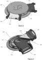
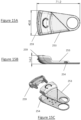
- FIGS. 1 and 2 show a front view and a rear view, respectively, of a garment 100 according to some embodiments of the present invention.
- the garment 100 is a belt.
- the garment 100 includes a securing portion 110.
- the securing portion 110 includes a first side 112 and a second side 114 that are configured to engage one another.
- the securing portion 110 includes a strap 116.
- the securing portion 110 is configured to secure the garment 100 to the wearer's body at or near the wearer's waist. According to the invention, the length of the securing portion 110 is adjustable (e.g., through the use of buckles, straps, or other similar mechanisms).
- the garment 100 includes a first sensor attachment portion 120 and a second sensor attachment portion 130.
- the first and second sensor attachment portions 120, 130 are substantially similar to one another.
- each of the first and second sensor attachment portions 120, 130 includes a plurality of sensors 140.
- the sensors 140 include at least one sensor of a first type of sensor and at least one sensor of a second type of sensor.
- the sensors 140 include more than two types of sensors (e.g., three types of sensors, four types of sensors, five types of sensors, etc.).
- the first type of sensor is an acoustic sensor.
- the second type of sensor is an electrode (e.g., a bio-potential sensor, which may be either wet or dry).
- each of the first and second sensor attachment portions 120, 130 has a first end and a second end, is joined to a first end of the securing portion 110 by a first hinge portion 150 at the respective first ends of the first and second sensor attachment portions 120, 130, and is joined to a second end of the securing portion 110 by a second hinge portion 160 at the respective second ends of the first and second sensor attachment portions 120, 130.
- the lengths of the first and second sensor attachment portions 12, 130 are adjustable (e.g., through the use of buckles, straps, or other similar mechanisms).
- one of the sensors 140 is integrated into each of the first and second hinge portions 150, 160.
- FIG. 3 shows an exploded view of the first hinge portion 150.
- the first and second hinge portions 150, 160 are substantially similar to one another, and, therefore, only the first hinge portion 150 will be described in detail herein.
- the first hinge portion 150 includes a base 151, an axis cover 152, a first hook including a first hook top portion 153 and a first hook bottom portion 154, a second hook including a second hook top portion 155 and a second hook bottom portion 156, and a cover 157.
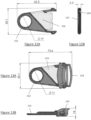
- FIG. 12A shows a front view of the assembled first hook top portion 153 and the first hook top portion 154, with dimensions thereof in millimeters included.
- FIG. 12B shows a side view of the assembled first hook top portion 153 and the first hook bottom portion 154, with dimensions thereof in millimeters included.
- first hinge portion 150 The elements of the first hinge portion 150 are oriented about a rotational axis 158, which, it will be it apparent to those of skill in the art, is an imaginary feature defined herein for the purpose of describing the first hinge portion 150, and not a physical element of the first hinge portion 150.
- first hook top portion 153 and the second hook top portion 155 are positioned on the axis cover 152, and are configured so as to be able to rotate about the rotational axis 158 with respect to the axis cover 152 and with respect to one another.
- the first hook top portion 153 and the second hook top portion 155 include stops configured to define a closest possible angular displacement of the first hook top portion 153 and the second hook top portion 155 with respect to one another.
- the cover 157 includes stops configured to define a furthest possible angular displacement of the first hook top portion 153 and the second hook top portion 155 with respect to one another.
- the first hook top portion 153 and the first hook bottom portion 154 define a strain relief therebetween through which wires may pass.
- the second hook top portion 155 and the second hook bottom portion 156 define a strain relief therebetween through which wires may pass.
- each of the first and second hooks includes a buckle 159. The buckles 159 are configured to adjustably attach to the first and second sensor attachment portions 120, 130 in accordance with known techniques.
- FIG. 13A shows a front view of the first hook top portion 153, the first hook bottom portion 154, and the buckle 159, with dimensions thereof in millimeters included.
- FIG. 13B shows a top view of the first hook top portion 153, the first hook bottom portion 154, and the buckle 159, with dimensions thereof in millimeters included.
- FIG. 14A shows a front view of the assembled first hinge portion 150, with dimensions thereof in millimeters included.
- FIG. 14B shows a top view of the assembled first hinge portion 150, with dimensions thereof in millimeters included.
- FIG. 15A shows a front view of another embodiment of a first hook including a first hook top portion 253, a first hook bottom portion 254, and a buckle 259, with dimensions thereof in millimeters included.
- FIG. 15B shows a side view of the embodiment of the first hook of FIG. 15A including the first hook top portion 253, the first hook bottom portion 254, and the buckle 259, with dimensions thereof in millimeters included.
- FIG. 15C shows an exploded view of the embodiment of the first hook of FIG. 15A including the first hook top portion 253, the first hook bottom portion 254, and the buckle 259.
- FIG. 4 shows an assembled view of the first hinge portion 150, the first and second hook top portions 153, 155 being positioned as far from one another as allowed by stops of the cover 157.
- FIG. 5 shows an assembled view of the first hinge portion 150, the cover 157 being removed to show the remaining elements of the first hinge portion 150, the first and second hook top portions 153, 155 being positioned closer to one another than in the position shown in FIG. 4 , but not abutting one another as defined by their respective stops.
- first and second hinge portions 150, 160 are configured such that, when their respective hook portions are at their closest angular displacement with respect to one another, the first and second sensor attachment portions 120, 130 are positioned with respect to one another so as to fit a pregnant mother having an abdomen circumference of 50 centimeters. In some embodiments, the first and second hinge portions 150, 160 are configured such that, when their respective hook portions are at their closest angular displacement with respect to one another, the first and second sensor attachment portions 120, 130 are positioned with respect to one another so as to fit a pregnant mother having an abdomen circumference of 55 centimeters.
- first and second hinge portions 150, 160 are configured such that, when their respective hook portions are at their closest angular displacement with respect to one another, the first and second sensor attachment portions 120, 130 are positioned with respect to one another so as to fit a pregnant mother having an abdomen circumference of 60 centimeters. In some embodiments, the first and second hinge portions 150, 160 are configured such that, when their respective hook portions are at their furthest angular displacement with respect to one another, the first and second sensor attachment portions 120, 130 are positioned with respect to one another so as to fit a pregnant mother having an abdomen circumference of 120 centimeters.
- first and second hinge portions 150, 160 are configured such that, when their respective hook portions are at their furthest angular displacement with respect to one another, the first and second sensor attachment portions 120, 130 are positioned with respect to one another so as to fit a pregnant mother having an abdomen circumference of 125 centimeters. In some embodiments, the first and second hinge portions 150, 160 are configured such that, when their respective hook portions are at their furthest angular displacement with respect to one another, the first and second sensor attachment portions 120, 130 are positioned with respect to one another so as to fit a pregnant mother having an abdomen circumference of 130 centimeters.
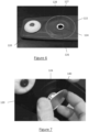
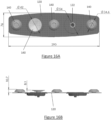
- FIG. 6 shows a portion of the first sensor attachment portion 120.
- each of the first sensor attachment portion 120 and the second sensor attachment portion 130 includes at least one flexible sensor mount 122, although only the first sensor attachment portion 120 is specifically illustrated in detail herein.
- the flexible sensor mount 122 includes a rigid portion 124 positioned within a flexible portion 126.
- the flexible portion 126 includes an inner region 127 that surrounds the rigid portion 124 and an outer region 128 that joins the remainder of the first sensor attachment portion 120.
- the rigid portion 124 is formed from a metal.
- the rigid portion 124 is formed from a plastic.
- the rigid portion 124 is formed from another rigid material.
- the flexible portion 126 is formed from an elastomeric material. In some embodiments, the flexible portion 126 is formed from silicone. In some embodiments, the flexible portion 126 is formed from another durable, flexible material.
- FIG. 16A shows a rear view of the first sensor attachment portion 120 with four (5) sensors 140 installed therein and one of the fixable sensor mounts 122 exposed, with dimensions thereof in millimeters included.
- Figure 16B shows a top view of the first sensor attachment portion 120 as shown in FIG. 16A , with dimensions thereof in millimeters included.
- the flexible portion 126 of the flexible sensor mount 122 is stretchable so as to provide suitable contact between a sensor housed therein and the curved profile of the skin of a subject's abdomen.
- the flexible portion 126 is stretchable with a spring coefficient of between 1 N/mm and 20 N/mm. In some embodiments, the flexible portion 126 is stretchable with a spring coefficient of between 1 N/mm and 15 N/mm. In some embodiments, the flexible portion 126 is stretchable with a spring coefficient of between 1 N/mm and 10 N/mm. In some embodiments, the flexible portion 126 is stretchable with a spring coefficient of between 1 N/mm and 7.5 N/mm. In some embodiments, the flexible portion 126 is stretchable with a spring coefficient of between 1 N/mm and 20 5/mm. In some embodiments, the flexible portion 126 is stretchable with a spring coefficient of between 1 N/mm and 4 N/mm.
- the flexible portion 126 is stretchable with a spring coefficient of between 1 N/mm and 3 N/mm. In some embodiments, the flexible portion 126 is stretchable with a spring coefficient of between 1 N/mm and 2 N/mm. In some embodiments, the flexible portion 126 is stretchable with a spring coefficient of between 1 N/mm and 1.5 N/mm. In some embodiments, the flexible portion 126 is stretchable with a spring coefficient of about 1.25 N/mm. In some embodiments, the flexible portion 126 is stretchable with a spring coefficient of 1.25 N/mm. In some embodiments, the flexible sensor mount is made from a viscoelastic material that conforms to the Kelvin-Voigt model.
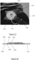
- FIG. 17 shows a perspective view of another embodiment of a hinge portion 1700 along with portions of another embodiment of sensor attachment portions 1750 and 1760.
- the hinge portion 1700 includes a circular base 1710 having a ring 1715 extending around a portion of its perimeter.
- the sensor attachment portions 1750 and 1760 include respective loop portions 1755 and 1765 that loop around the ring 1715 in a manner such that the sensor attachment portions 1750 and 1760 may pivot about the hinge portion 1700 in order that the sensor attachment portions 1750 and 1760 follow the contours of the abdomen of the wearer, as described herein.
- FIG. 18 shows a top view of a portion of the sensor attachment portion 1750.
- the sensor attachment portion 1750 is surrounded by a multi-layered structure including a first fabric layer 1800, a second fabric layer 1810, a flexible printed circuit board 1820, an elastic polymer sheet 1830, a third fabric layer 1840, and a fourth fabric layer 1850.
- the sensor attachment portion 1750 is configured such that the first fabric layer 1800 faces the skin of the wearer when a garment including the sensor attachment portion 1750 is worn.
- the first fabric layer 1800 and the fourth fabric layer 1850 include a coated elastic fabric.
- the elastic fabric includes a polyether-polyurea copolymer such as that commercialized under the trademark LYCRA ® by E. I.
- the elastic fabric is coated with thermoplastic polyurethane ("TPU").
- TPU thermoplastic polyurethane
- the second fabric layer 1810 and the third fabric layer 1840 include a stiff woven fabric such as gabardine, such as with cotton or texturized polyester, or blended fabrics.
- the flexible printed circuit board 1830 is coupled to a sensor that is housed in the sensor attachment portion 1750.
- the flexible printed circuit board 1830 includes a flexible substrate and flexible conductors.
- the flexible substrate includes a Polyimide (PI), TPU, or a Thermoplastic Elastomer (TPE).
- the flexible conductor includes copper or a stretchable conductive ink.
- the elastic polymer sheet 1830 includes TPU.
- the combination of layers described above causes the sensor attachment portion 1750 to operate as described herein.
- different combinations of layers may be present and/or the layers may be arranged in a different sequence than that described above.
- the garment 100 includes one of the flexible sensor mounts 122 for each of the sensors 140. In some embodiments, the garment 100 includes one of the flexible sensor mounts 122 for some, but not all, of the sensors 140. In some embodiments, the garment 100 includes a standard rigid sensor mount (not shown in detail herein) for at least one of the sensors 140, whereby the at least one of the sensors mounted in a rigid sensor mount is not movable with respect to the first or second sensor attachment portion 120 or 130 in the manner described above.
- the garment 100 includes one of the flexible sensor mounts 122 for each of the sensors 140 that is the first type of sensor (e.g., an acoustic sensor) and includes a rigid sensor mount for each of the sensors 140 that is the second type of sensor (e.g., a bio-potential sensor).
- the first type of sensor e.g., an acoustic sensor
- the second type of sensor e.g., a bio-potential sensor
- FIG. 7 shows one of the sensors 140 being positioned within the flexible sensor mount 122.
- the sensor 140 and the rigid portion 124 are fixed in position with respect to one another, the inner region 127 of the flexible portion 126 is fixed with respect to the rigid portion 124, the outer region 128 of the flexible portion 126 is fixed with respect to the remainder of the first sensor attachment portion 120, and the flexible portion 126 is deformable such that the inner region 127 of the flexible portion 126 moves with respect to the outer region 128 of the flexible portion 126. Consequently, in some embodiments, each flexible sensor mount 122, the flexible sensor mount 122 allows one of the sensors 140 that is mounted therein to move with respect to the first sensor attachment portion 120.
- FIG. 8 shows the sensor 140 as positioned in the rigid portion 122 and manually rotated with respect to the sensor attachment portion 120.
- FIG. 9 shows the sensor 140 as positioned in the rigid portion 122 and rotated with respect to the sensor attachment portion 120 due to its position against a simulated wearer. In both FIG. 8 and FIG. 9 , the rotation of the sensor 140 is allowed by the flexibility of the flexible portion 126.
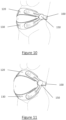
- FIGS. 10 and 11 show an embodiment of the garment 100 as worn by pregnant mothers having differently sized abdomens.
- FIG. 10 shows an embodiment of the garment 100 as worn by a pregnant mother having a comparatively smaller abdomen.
- FIG. 11 shows an embodiment of the garment 100 as worn by a pregnant mother having a comparatively larger abdomen.
- the garment 100 i.e., the securing portion 110, the first sensor attachment portion 120, the second sensor attachment portion 130, the first hinge portion 150, and the second hinge portion 160
- the garment 100 are configured such that, when the garment 100 is donned by a pregnant mother and the securing portion 110 and the first and second sensor attachment portions 120, 130 are secured and tightened so as to fit snugly about the wearer's abdomen, the positions of the first and sensor attachment portions 120, 130 will come to an equilibrium in which they, and the sensors 140 attached thereto, will anatomically follow the curvature of the wearer's abdomen, such that they are flush with the wearer's abdomen (i.e., the first and second sensor attachment portions 120, 130 self-adjust).
- such adjustment is facilitated by the flexible portions 124 in which the sensors 140 are mounted. Consequently, as may be seen in FIGS. 10 and 11 , when the garment 100 is donned by a pregnant mother having a comparatively smaller abdomen, the first and sensor attachment portions 120, 130 will be positioned comparatively close to one another, and when the garment 100 is donned by a pregnant mother having a comparatively larger abdomen, the first and second sensor attachment portions 120, 130 will be positioned comparatively far from one another.
- At least one of the elements described herein is made from a plastic material. In some embodiments, at least one of the elements described herein is made from Acrylonitrile Butadiene Styrene ("ABS") plastic. In some embodiments, at least one of the elements described herein is made from a polycarbonate plastic. In some embodiments, at least one of the materials described herein is made from one of the polycarbonate plastics commercialized under the trademark MAKROLON ® by Bayer Material Science AG of Leverkusen, Germany. In some embodiments, at least one of the elements described herein is made from a nylon plastic.
- ABS Acrylonitrile Butadiene Styrene
- at least one of the elements described herein is made from a polycarbonate plastic. In some embodiments, at least one of the materials described herein is made from one of the polycarbonate plastics commercialized under the trademark MAKROLON ® by Bayer Material Science AG of Leverkusen, Germany. In some embodiments, at least one of the elements described herein
Landscapes
- Health & Medical Sciences (AREA)
- Life Sciences & Earth Sciences (AREA)
- Engineering & Computer Science (AREA)
- Heart & Thoracic Surgery (AREA)
- Public Health (AREA)
- Veterinary Medicine (AREA)
- Biophysics (AREA)
- Pathology (AREA)
- Physics & Mathematics (AREA)
- Biomedical Technology (AREA)
- General Health & Medical Sciences (AREA)
- Medical Informatics (AREA)
- Molecular Biology (AREA)
- Surgery (AREA)
- Animal Behavior & Ethology (AREA)
- Pregnancy & Childbirth (AREA)
- Gynecology & Obstetrics (AREA)
- Reproductive Health (AREA)
- Textile Engineering (AREA)
- Measurement Of The Respiration, Hearing Ability, Form, And Blood Characteristics Of Living Organisms (AREA)
- Measuring And Recording Apparatus For Diagnosis (AREA)
- Outer Garments And Coats (AREA)
- Outerwear In General, And Traditional Japanese Garments (AREA)
Claims (15)
- Kleidungsstück (100), wobei das Kleidungsstück (100) ein sich selbst einstellendes Kleidungsstück (100) ist, das so konfiguriert ist, dass es von einer schwangeren menschlichen Person während eines Schwangerschaftsverlaufs getragen werden kann und dass es die Positionierung von mindestens einem in das Kleidungsstück (100) integrierten Sensor (140) während des Schwangerschaftsverlaufs selbst einstellt;wobei das Kleidungsstück (100) Folgendes aufweist:- einen Befestigungsbereich (110), der betätigbar ist, um das Kleidungsstück (100) abnehmbar um einen Bauch eines Trägers zu befestigen;- mindestens einen Sensorbefestigungsbereich (120, 130), der drehbar an dem Befestigungsbereich (110) angebracht ist, wobei jeder des mindestens einen Sensorbefestigungsbereichs (120, 130) mindestens eine flexible Sensorhalterung (122) enthält, die so konfiguriert ist, dass sie einen Sensor (140) darin aufnimmt und festhält; und- mindestens einen Sensor (140), wobei jeder des mindestens einen Sensors (140) in einer entsprechenden der mindestens einen flexiblen Sensorhalterung (122) des mindestens einen Sensorbefestigungsbereichs (120, 130) aufgenommen ist;wobei der Befestigungsbereich (110) und der mindestens eine Sensorbefestigungsbereich (120, 130) so konfiguriert sind, dass, wenn der Befestigungsbereich (110) um den Rücken eines Trägers befestigt ist, der mindestens eine Sensorbefestigungsbereich (120, 130) sich in Bezug auf den Befestigungsbereich (110) dreht, um den mindestens einen Sensorbefestigungsbereich (120, 130) über (a) einen oberen Bereich des Bauches des Trägers oder (b) einen unteren Bereich des Bauches des Trägers selbst zu positionieren, undwobei jede der mindestens einen flexiblen Sensorhalterung (122) so konfiguriert ist, dass sie einen darin aufgenommenen Sensor (140) so ausrichtet, dass er kontinuierlich mit der Haut des Trägers bündig ist, wenn das Kleidungsstück (100) von dem Träger getragen wird, und sich im Laufe der Schwangerschaft selbst anpasst,dadurch gekennzeichnet, dassdas Kleidungsstück (100) ferner mindestens ein Drehgelenk aufweist, wobei jedes des mindestens einen Drehgelenks ein Ende des Befestigungsbereichs (110) mit einem Ende des mindestens einen Sensorbefestigungsbereichs (120, 130) verbindet, wobei die Länge des Befestigungsbereichs (110) einstellbar ist.
- Kleidungsstück (100) nach Anspruch 1,wobei der mindestens eine Sensor (140) mindestens eine Elektrode aufweist; und/oderwobei der mindestens eine Sensor (140) mindestens einen akustischen Sensor (140) aufweist.
- Kleidungsstück (100) nach Anspruch 1 oder 2,
wobei der mindestens eine Sensorbefestigungsbereich (120, 130) zwei Sensorbefestigungsbereiche (120, 130) aufweist. - Kleidungsstück (100) nach Anspruch 3,
wobei ein erster der Sensorbefestigungsbereiche (120, 130) so konfiguriert ist, dass er sich um einen oberen Bereich des Bauchs des Trägers erstreckt, und ein zweiter der Sensorbefestigungsbereiche (120, 130) so konfiguriert ist, dass er sich um einen unteren Bereich des Bauchs des Trägers erstreckt. - Kleidungsstück (100) nach einem der Ansprüche 1 bis 4,wobei jeder der Sensorbefestigungsbereiche (120, 130) eine Mehrzahl der flexiblen Sensorhalterungen (122) aufweist, wobei der mindestens eine Sensor (140) eine Mehrzahl von Sensoren aufweist und wobei jeder der Mehrzahl von Sensoren in einer entsprechenden der Mehrzahl von flexiblen Sensorhalterungen (122) aufgenommen ist,wobei jeder der Sensorbefestigungsbereiche (120, 130) vorzugsweise fünf Sensorhalterungen (122) aufweist.
- Kleidungsstück (100) nach einem der Ansprüche 1 bis 5,
wobei das mindestens eine Drehgelenk einen Sensor (140) aufweist. - Kleidungsstück (100) nach einem der Ansprüche 1 bis 6,
wobei das mindestens eine Drehgelenk zwei Drehgelenke aufweist, wobei ein erstes der Drehgelenke ein erstes Ende des Befestigungsbereichs (110) mit einem ersten Ende des mindestens einen Sensorbefestigungsbereichs (120, 130) verbindet, und wobei ein zweites der Drehgelenke ein zweites Ende des Befestigungsbereichs (110) mit einem zweiten Ende des mindestens einen Sensorbefestigungsbereichs (120, 130) verbindet. - Kleidungsstück (100) nach Anspruch 7,
wobei der mindestens eine Sensorbefestigungsbereich (120, 130) zwei Sensorbefestigungsbereiche (120, 130) aufweist, wobei das erste der Drehgelenke ein erstes Ende des Befestigungsbereichs (110) mit (a) einem ersten Ende eines ersten der Sensorbefestigungsbereiche (120, 130) und (b) einem ersten Ende eines zweiten der Sensorbefestigungsbereiche (120, 130) verbindet, und wobei ein zweites der Drehgelenke ein zweites Ende des Befestigungsbereichs (110) mit (a) einem zweiten Ende eines ersten der Sensorbefestigungsbereiche (120, 130) und (b) einem zweiten Ende eines zweiten der Sensorbefestigungsbereiche (120, 130) verbindet. - Kleidungsstück (100) nach einem der Ansprüche 1 bis 8,wobei mindestens eine der mindestens einen flexiblen Sensorhalterung (122) einen flexiblen Bereich (126) aufweist, der ein Elastomermaterial enthält,wobei das Elastomematerial vorzugsweise einen Federkoeffizienten zwischen 1 N/mm und 20 N/mm aufweist.
- Kleidungsstück (100) nach Anspruch 9,
wobei die mindestens eine der mindestens einen Sensorhalterung (122) einen steifen Bereich (124) aufweist, der innerhalb einer Öffnung in dem flexiblen Bereich (126) positioniert ist, wobei der steife Bereich (124) so konfiguriert ist, dass er einen des mindestens einen Sensors (140) darin aufnimmt. - Kleidungsstück (100) nach einem der Ansprüche 1 bis 10,
wobei jede der mindestens einen Sensorhalterung (122) so konfiguriert ist, dass sie einen darin aufgenommenen Sensor (140) so ausrichtet, dass er mit der Haut des Trägers bündig ist. - Verfahren zum Positionieren mindestens eines Sensors (140), so dass er mit der Haut auf dem Bauch eines Trägers bündig ist, wobei das Verfahren Folgendes aufweist:- Bereitstellen eines Kleidungsstücks (100), welches Folgendes aufweist:- einen Befestigungsbereich (110), der betätigbar ist, um das Kleidungsstück (100) abnehmbar um einen Bauch eines Trägers zu befestigen;- mindestens einen Sensorbefestigungsbereich (120, 130), der drehbar an dem Befestigungsbereich (110) angebracht ist, wobei jeder des mindestens einen Sensorbefestigungsbereichs (120, 130) mindestens eine flexible Sensorhalterung (122) enthält, die so konfiguriert ist, dass sie einen Sensor (140) darin aufnimmt und festhält; und- mindestens einen Sensor (140), wobei jeder des mindestens einen Sensors (140) in einer entsprechenden der mindestens einen flexiblen Sensorhalterung (122) des mindestens einen Sensorbefestigungsbereichs (120, 130) aufgenommen ist;wobei der Befestigungsbereich (110) und der mindestens eine Sensorbefestigungsbereich (120, 130) so konfiguriert sind, dass, wenn der Befestigungsbereich (110) um den Rücken eines Trägers befestigt ist, der mindestens eine Sensorbefestigungsbereich (120, 130) sich in Bezug auf den Befestigungsbereich (110) dreht, so dass er sich um (a) einen oberen Bereich des Bauches des Trägers oder (b) einen unteren Bereich des Bauches des Trägers erstreckt, undwobei jede der mindestens einen Sensorhalterung (122) so konfiguriert ist, dass sie einen darin aufgenommenen Sensor (140) so ausrichtet, dass er mit der Haut des Trägers bündig ist, wenn das Kleidungsstück (100) von dem Träger getragen wird;Positionieren des Kleidungsstücks (100), so dass es einen mittleren Bereich des Trägers umgibt, so dass sich der Befestigungsbereich (110) um einen Rücken des Trägers und der mindestens eine Sensorbefestigungsbereich (120, 130) um einen Bauch des Trägers erstreckt;Befestigen des Befestigungsbereichs (110), um das Kleidungsstück (100) den mittleren Bereich des Trägers umgebend zu halten,wobei der mindestens eine Sensorbefestigungsbereich (120, 130) entweder um einen oberen Bereich eines Bauchs des Trägers oder um einen unteren Bereich eines Bauchs des Trägers angeordnet ist, undwobei sich die mindestens eine flexible Sensorhalterung (122) so biegt, dass der eine des mindestens einen Sensors (140), der darin aufgenommen ist, bündig mit der Haut des Trägers positioniert werden kann,dadurch gekennzeichnet, dassdas Kleidungsstück (100) ferner mindestens ein Drehgelenk aufweist, wobei jedes des mindestens einen Drehgelenks ein Ende des Befestigungsbereichs (110) mit einem Ende des mindestens einen Sensorbefestigungsbereichs (120, 130) verbindet, wobei die Länge des Befestigungsbereichs (110) einstellbar ist.
- Verfahren nach Anspruch 12,
wobei der mindestens eine Sensorbefestigungsbereich (120, 130) zwei Sensorbefestigungsbereiche (120, 130) aufweist, und wobei, wenn der Befestigungsbereich (110) befestigt ist, ein erster der Sensorbefestigungsbereiche (120, 130) um einen oberen Bereich des Bauchs des Trägers positioniert ist und ein zweiter der Sensorbefestigungsbereiche (120, 130) um einen unteren Bereich eines Bauchs des Trägers positioniert ist. - Verfahren nach Anspruch 12 oder 13,
wobei der Träger ein schwangerer Mensch ist. - Verfahren nach einem der Ansprüche 12 bis 14,
wobei der mindestens eine Sensor (140) zehn Sensoren aufweist; und/oder wobei der mindestens eine Sensor (140) mindestens eine Elektrode und mindestens einen akustischen Sensor (140) aufweist.
Applications Claiming Priority (2)
| Application Number | Priority Date | Filing Date | Title |
|---|---|---|---|
| US201862632113P | 2018-02-19 | 2018-02-19 | |
| PCT/IB2019/000170 WO2019159009A2 (en) | 2018-02-19 | 2019-02-19 | System and method for maintaining sensor contact |
Publications (3)
| Publication Number | Publication Date |
|---|---|
| EP3755988A2 EP3755988A2 (de) | 2020-12-30 |
| EP3755988A4 EP3755988A4 (de) | 2021-11-17 |
| EP3755988B1 true EP3755988B1 (de) | 2024-01-24 |
Family
ID=67617331
Family Applications (1)
| Application Number | Title | Priority Date | Filing Date |
|---|---|---|---|
| EP19754473.7A Active EP3755988B1 (de) | 2018-02-19 | 2019-02-19 | System und verfahren zur aufrechterhaltung eines sensorkontakts |
Country Status (4)
| Country | Link |
|---|---|
| US (4) | US10617355B2 (de) |
| EP (1) | EP3755988B1 (de) |
| CN (1) | CN112005093A (de) |
| WO (1) | WO2019159009A2 (de) |
Families Citing this family (3)
| Publication number | Priority date | Publication date | Assignee | Title |
|---|---|---|---|---|
| US10595792B2 (en) * | 2017-06-11 | 2020-03-24 | Fetal Life Llc | Tocodynamometer GPS alert system |
| WO2025255553A1 (en) * | 2024-06-06 | 2025-12-11 | Emfit Corp. | Multifunctional health and activity tracker for wearable, under-mattress, and tactical use |
| CN119157509A (zh) * | 2024-11-08 | 2024-12-20 | 西安存济妇产医院有限公司 | 一种产科用胎心智能监测方法及系统 |
Family Cites Families (13)
| Publication number | Priority date | Publication date | Assignee | Title |
|---|---|---|---|---|
| US20170262078A1 (en) | 2004-02-04 | 2017-09-14 | Anascape, Ltd. | PDA with 6DOF Sensing |
| CA2645604C (en) * | 2005-05-18 | 2013-12-10 | Rachelle Van Wyk | System, method, and kit for positioning a monitor transducer on a patient |
| US8396229B2 (en) * | 2006-08-07 | 2013-03-12 | Nuvo Group Ltd. | Musical maternity belt |
| US8560044B2 (en) * | 2007-05-16 | 2013-10-15 | Medicomp, Inc. | Garment accessory with electrocardiogram sensors |
| GB0810843D0 (en) * | 2008-06-13 | 2008-07-23 | Monica Healthcare Ltd | Electrode and electrode positioning arrangement for abdominal fetal electrocardiogram detection |
| US9579055B1 (en) * | 2008-10-17 | 2017-02-28 | Orbital Research Inc. | Apparatus for non-invasive fetal biosignal acquisition |
| US9662015B2 (en) * | 2013-03-04 | 2017-05-30 | Hello Inc. | System or device with wearable devices having one or more sensors with assignment of a wearable device user identifier to a wearable device user |
| WO2015088863A2 (en) * | 2013-12-09 | 2015-06-18 | President And Fellows Of Harvard College | Assistive flexible suits, flexible suit systems, and methods for making and control thereof to assist human mobility |
| US9763616B2 (en) * | 2014-03-27 | 2017-09-19 | Smart Human Dynamics, Inc. | Systems, devices, and methods for tracking abdominal orientation and activity |
| US9572504B2 (en) * | 2015-03-16 | 2017-02-21 | Nuvo Group Ltd. | Continuous non-invasive monitoring of a pregnant human subject |
| TWI587837B (zh) * | 2016-03-17 | 2017-06-21 | 南臺科技大學 | 胎動量測裝置 |
| US20170311659A1 (en) * | 2016-04-29 | 2017-11-02 | Easton Baseball / Softball Inc. | Two-piece articulating chest protector with stretchable hinge |
| CN107343783A (zh) * | 2016-09-29 | 2017-11-14 | 苏州能斯达电子科技有限公司 | 一种胎心率、胎动和宫缩智能监测系统及方法 |
-
2019
- 2019-02-19 EP EP19754473.7A patent/EP3755988B1/de active Active
- 2019-02-19 WO PCT/IB2019/000170 patent/WO2019159009A2/en not_active Ceased
- 2019-02-19 US US16/279,665 patent/US10617355B2/en active Active
- 2019-02-19 CN CN201980026482.9A patent/CN112005093A/zh active Pending
-
2020
- 2020-04-13 US US16/846,836 patent/US11534109B2/en active Active
-
2022
- 2022-12-23 US US18/146,019 patent/US20230233148A1/en not_active Abandoned
-
2024
- 2024-01-18 US US18/416,232 patent/US20240225541A1/en active Pending
Also Published As
| Publication number | Publication date |
|---|---|
| US11534109B2 (en) | 2022-12-27 |
| EP3755988A2 (de) | 2020-12-30 |
| US10617355B2 (en) | 2020-04-14 |
| US20200375536A1 (en) | 2020-12-03 |
| US20240225541A1 (en) | 2024-07-11 |
| WO2019159009A2 (en) | 2019-08-22 |
| WO2019159009A3 (en) | 2019-10-03 |
| CN112005093A (zh) | 2020-11-27 |
| EP3755988A4 (de) | 2021-11-17 |
| US20230233148A1 (en) | 2023-07-27 |
| US20190254598A1 (en) | 2019-08-22 |
Similar Documents
| Publication | Publication Date | Title |
|---|---|---|
| US20240225541A1 (en) | System and method for maintaining sensor contact | |
| US12138445B2 (en) | Garments for wearable cardiac monitoring and treatment devices | |
| US12551693B2 (en) | Adhesively coupled wearable medical device | |
| EP2994041B1 (de) | Herzfrequenzmonitor beim schwimmen | |
| US3534727A (en) | Biomedical electrode arrangement | |
| ES3053858T3 (en) | Wearable defibrillation devices | |
| US9451897B2 (en) | Body adherent patch with electronics for physiologic monitoring | |
| US11857329B2 (en) | Modular garment for a wearable medical device | |
| US10143383B2 (en) | Attachable monitoring device | |
| US20200375537A1 (en) | Prenatal Monitoring Device | |
| US20250018175A1 (en) | Wearable cardioverter defibrillator with breast support | |
| US20220370788A1 (en) | Wearable Medical Device with Removable Support Garment | |
| WO2017185050A1 (en) | Sensor assemblies; sensor-enabled garments and objects; devices and systems for data collection | |
| US12332085B2 (en) | Wearable apparatus | |
| CN210043463U (zh) | 一种可监测并矫正坐姿的智能背带 | |
| US20110213258A1 (en) | Strap based reliable heart rate or electro cardiogram monitor with wireless data transmission | |
| CN209678781U (zh) | 孕妇专用传感腹带 | |
| US20260053216A1 (en) | Sensorised wearable textile device, garment incorporating the same and corresponding manufacturing method | |
| CN121550584A (zh) | 电极片基座可重复利用的背带式可穿戴体外除颤器 | |
| CN121754156A (zh) | 一种用于采集腹式呼吸信号的呼吸抱枕 |
Legal Events
| Date | Code | Title | Description |
|---|---|---|---|
| STAA | Information on the status of an ep patent application or granted ep patent |
Free format text: STATUS: THE INTERNATIONAL PUBLICATION HAS BEEN MADE |
|
| PUAI | Public reference made under article 153(3) epc to a published international application that has entered the european phase |
Free format text: ORIGINAL CODE: 0009012 |
|
| STAA | Information on the status of an ep patent application or granted ep patent |
Free format text: STATUS: REQUEST FOR EXAMINATION WAS MADE |
|
| 17P | Request for examination filed |
Effective date: 20200825 |
|
| AK | Designated contracting states |
Kind code of ref document: A2 Designated state(s): AL AT BE BG CH CY CZ DE DK EE ES FI FR GB GR HR HU IE IS IT LI LT LU LV MC MK MT NL NO PL PT RO RS SE SI SK SM TR |
|
| AX | Request for extension of the european patent |
Extension state: BA ME |
|
| RIN1 | Information on inventor provided before grant (corrected) |
Inventor name: WEISS, NOGA Inventor name: DIVINSKY, ILYA Inventor name: OZ, OREN |
|
| RIN1 | Information on inventor provided before grant (corrected) |
Inventor name: WEISS, NOGA Inventor name: OZ, OREN Inventor name: DIVINSKY, ILYA |
|
| DAV | Request for validation of the european patent (deleted) | ||
| DAX | Request for extension of the european patent (deleted) | ||
| A4 | Supplementary search report drawn up and despatched |
Effective date: 20211019 |
|
| RIC1 | Information provided on ipc code assigned before grant |
Ipc: A61B 5/00 20060101ALI20211013BHEP Ipc: G01N 1/34 20060101AFI20211013BHEP |
|
| GRAP | Despatch of communication of intention to grant a patent |
Free format text: ORIGINAL CODE: EPIDOSNIGR1 |
|
| STAA | Information on the status of an ep patent application or granted ep patent |
Free format text: STATUS: GRANT OF PATENT IS INTENDED |
|
| RIC1 | Information provided on ipc code assigned before grant |
Ipc: A61B 5/00 20060101ALI20230711BHEP Ipc: G01N 1/34 20060101AFI20230711BHEP |
|
| INTG | Intention to grant announced |
Effective date: 20230811 |
|
| GRAS | Grant fee paid |
Free format text: ORIGINAL CODE: EPIDOSNIGR3 |
|
| GRAA | (expected) grant |
Free format text: ORIGINAL CODE: 0009210 |
|
| STAA | Information on the status of an ep patent application or granted ep patent |
Free format text: STATUS: THE PATENT HAS BEEN GRANTED |
|
| AK | Designated contracting states |
Kind code of ref document: B1 Designated state(s): AL AT BE BG CH CY CZ DE DK EE ES FI FR GB GR HR HU IE IS IT LI LT LU LV MC MK MT NL NO PL PT RO RS SE SI SK SM TR |
|
| REG | Reference to a national code |
Ref country code: GB Ref legal event code: FG4D |
|
| REG | Reference to a national code |
Ref country code: CH Ref legal event code: EP |
|
| REG | Reference to a national code |
Ref country code: IE Ref legal event code: FG4D |
|
| REG | Reference to a national code |
Ref country code: DE Ref legal event code: R096 Ref document number: 602019045610 Country of ref document: DE |
|
| REG | Reference to a national code |
Ref country code: LT Ref legal event code: MG9D |
|
| REG | Reference to a national code |
Ref country code: NL Ref legal event code: FP |
|
| PG25 | Lapsed in a contracting state [announced via postgrant information from national office to epo] |
Ref country code: IS Free format text: LAPSE BECAUSE OF FAILURE TO SUBMIT A TRANSLATION OF THE DESCRIPTION OR TO PAY THE FEE WITHIN THE PRESCRIBED TIME-LIMIT Effective date: 20240524 |
|
| PG25 | Lapsed in a contracting state [announced via postgrant information from national office to epo] |
Ref country code: LT Free format text: LAPSE BECAUSE OF FAILURE TO SUBMIT A TRANSLATION OF THE DESCRIPTION OR TO PAY THE FEE WITHIN THE PRESCRIBED TIME-LIMIT Effective date: 20240124 |
|
| PG25 | Lapsed in a contracting state [announced via postgrant information from national office to epo] |
Ref country code: GR Free format text: LAPSE BECAUSE OF FAILURE TO SUBMIT A TRANSLATION OF THE DESCRIPTION OR TO PAY THE FEE WITHIN THE PRESCRIBED TIME-LIMIT Effective date: 20240425 |
|
| REG | Reference to a national code |
Ref country code: AT Ref legal event code: MK05 Ref document number: 1652529 Country of ref document: AT Kind code of ref document: T Effective date: 20240124 |
|
| PG25 | Lapsed in a contracting state [announced via postgrant information from national office to epo] |
Ref country code: RS Free format text: LAPSE BECAUSE OF FAILURE TO SUBMIT A TRANSLATION OF THE DESCRIPTION OR TO PAY THE FEE WITHIN THE PRESCRIBED TIME-LIMIT Effective date: 20240424 Ref country code: HR Free format text: LAPSE BECAUSE OF FAILURE TO SUBMIT A TRANSLATION OF THE DESCRIPTION OR TO PAY THE FEE WITHIN THE PRESCRIBED TIME-LIMIT Effective date: 20240124 |
|
| PG25 | Lapsed in a contracting state [announced via postgrant information from national office to epo] |
Ref country code: ES Free format text: LAPSE BECAUSE OF FAILURE TO SUBMIT A TRANSLATION OF THE DESCRIPTION OR TO PAY THE FEE WITHIN THE PRESCRIBED TIME-LIMIT Effective date: 20240124 |
|
| PG25 | Lapsed in a contracting state [announced via postgrant information from national office to epo] |
Ref country code: AT Free format text: LAPSE BECAUSE OF FAILURE TO SUBMIT A TRANSLATION OF THE DESCRIPTION OR TO PAY THE FEE WITHIN THE PRESCRIBED TIME-LIMIT Effective date: 20240124 |
|
| PG25 | Lapsed in a contracting state [announced via postgrant information from national office to epo] |
Ref country code: RS Free format text: LAPSE BECAUSE OF FAILURE TO SUBMIT A TRANSLATION OF THE DESCRIPTION OR TO PAY THE FEE WITHIN THE PRESCRIBED TIME-LIMIT Effective date: 20240424 Ref country code: NO Free format text: LAPSE BECAUSE OF FAILURE TO SUBMIT A TRANSLATION OF THE DESCRIPTION OR TO PAY THE FEE WITHIN THE PRESCRIBED TIME-LIMIT Effective date: 20240424 Ref country code: LT Free format text: LAPSE BECAUSE OF FAILURE TO SUBMIT A TRANSLATION OF THE DESCRIPTION OR TO PAY THE FEE WITHIN THE PRESCRIBED TIME-LIMIT Effective date: 20240124 Ref country code: IS Free format text: LAPSE BECAUSE OF FAILURE TO SUBMIT A TRANSLATION OF THE DESCRIPTION OR TO PAY THE FEE WITHIN THE PRESCRIBED TIME-LIMIT Effective date: 20240524 Ref country code: HR Free format text: LAPSE BECAUSE OF FAILURE TO SUBMIT A TRANSLATION OF THE DESCRIPTION OR TO PAY THE FEE WITHIN THE PRESCRIBED TIME-LIMIT Effective date: 20240124 Ref country code: GR Free format text: LAPSE BECAUSE OF FAILURE TO SUBMIT A TRANSLATION OF THE DESCRIPTION OR TO PAY THE FEE WITHIN THE PRESCRIBED TIME-LIMIT Effective date: 20240425 Ref country code: FI Free format text: LAPSE BECAUSE OF FAILURE TO SUBMIT A TRANSLATION OF THE DESCRIPTION OR TO PAY THE FEE WITHIN THE PRESCRIBED TIME-LIMIT Effective date: 20240124 Ref country code: ES Free format text: LAPSE BECAUSE OF FAILURE TO SUBMIT A TRANSLATION OF THE DESCRIPTION OR TO PAY THE FEE WITHIN THE PRESCRIBED TIME-LIMIT Effective date: 20240124 Ref country code: BG Free format text: LAPSE BECAUSE OF FAILURE TO SUBMIT A TRANSLATION OF THE DESCRIPTION OR TO PAY THE FEE WITHIN THE PRESCRIBED TIME-LIMIT Effective date: 20240124 Ref country code: AT Free format text: LAPSE BECAUSE OF FAILURE TO SUBMIT A TRANSLATION OF THE DESCRIPTION OR TO PAY THE FEE WITHIN THE PRESCRIBED TIME-LIMIT Effective date: 20240124 |
|
| PG25 | Lapsed in a contracting state [announced via postgrant information from national office to epo] |
Ref country code: PT Free format text: LAPSE BECAUSE OF FAILURE TO SUBMIT A TRANSLATION OF THE DESCRIPTION OR TO PAY THE FEE WITHIN THE PRESCRIBED TIME-LIMIT Effective date: 20240524 Ref country code: PL Free format text: LAPSE BECAUSE OF FAILURE TO SUBMIT A TRANSLATION OF THE DESCRIPTION OR TO PAY THE FEE WITHIN THE PRESCRIBED TIME-LIMIT Effective date: 20240124 |
|
| PG25 | Lapsed in a contracting state [announced via postgrant information from national office to epo] |
Ref country code: SE Free format text: LAPSE BECAUSE OF FAILURE TO SUBMIT A TRANSLATION OF THE DESCRIPTION OR TO PAY THE FEE WITHIN THE PRESCRIBED TIME-LIMIT Effective date: 20240124 Ref country code: PT Free format text: LAPSE BECAUSE OF FAILURE TO SUBMIT A TRANSLATION OF THE DESCRIPTION OR TO PAY THE FEE WITHIN THE PRESCRIBED TIME-LIMIT Effective date: 20240524 Ref country code: PL Free format text: LAPSE BECAUSE OF FAILURE TO SUBMIT A TRANSLATION OF THE DESCRIPTION OR TO PAY THE FEE WITHIN THE PRESCRIBED TIME-LIMIT Effective date: 20240124 Ref country code: LV Free format text: LAPSE BECAUSE OF FAILURE TO SUBMIT A TRANSLATION OF THE DESCRIPTION OR TO PAY THE FEE WITHIN THE PRESCRIBED TIME-LIMIT Effective date: 20240124 |
|
| REG | Reference to a national code |
Ref country code: DE Ref legal event code: R119 Ref document number: 602019045610 Country of ref document: DE |
|
| REG | Reference to a national code |
Ref country code: CH Ref legal event code: PL |
|
| REG | Reference to a national code |
Ref country code: NL Ref legal event code: MM Effective date: 20240301 |
|
| PG25 | Lapsed in a contracting state [announced via postgrant information from national office to epo] |
Ref country code: DK Free format text: LAPSE BECAUSE OF FAILURE TO SUBMIT A TRANSLATION OF THE DESCRIPTION OR TO PAY THE FEE WITHIN THE PRESCRIBED TIME-LIMIT Effective date: 20240124 |
|
| PG25 | Lapsed in a contracting state [announced via postgrant information from national office to epo] |
Ref country code: SM Free format text: LAPSE BECAUSE OF FAILURE TO SUBMIT A TRANSLATION OF THE DESCRIPTION OR TO PAY THE FEE WITHIN THE PRESCRIBED TIME-LIMIT Effective date: 20240124 |
|
| PG25 | Lapsed in a contracting state [announced via postgrant information from national office to epo] |
Ref country code: LU Free format text: LAPSE BECAUSE OF NON-PAYMENT OF DUE FEES Effective date: 20240219 |
|
| PG25 | Lapsed in a contracting state [announced via postgrant information from national office to epo] |
Ref country code: CH Free format text: LAPSE BECAUSE OF NON-PAYMENT OF DUE FEES Effective date: 20240229 |
|
| PG25 | Lapsed in a contracting state [announced via postgrant information from national office to epo] |
Ref country code: EE Free format text: LAPSE BECAUSE OF FAILURE TO SUBMIT A TRANSLATION OF THE DESCRIPTION OR TO PAY THE FEE WITHIN THE PRESCRIBED TIME-LIMIT Effective date: 20240124 Ref country code: CZ Free format text: LAPSE BECAUSE OF FAILURE TO SUBMIT A TRANSLATION OF THE DESCRIPTION OR TO PAY THE FEE WITHIN THE PRESCRIBED TIME-LIMIT Effective date: 20240124 |
|
| REG | Reference to a national code |
Ref country code: DE Ref legal event code: R097 Ref document number: 602019045610 Country of ref document: DE |
|
| PG25 | Lapsed in a contracting state [announced via postgrant information from national office to epo] |
Ref country code: SK Free format text: LAPSE BECAUSE OF FAILURE TO SUBMIT A TRANSLATION OF THE DESCRIPTION OR TO PAY THE FEE WITHIN THE PRESCRIBED TIME-LIMIT Effective date: 20240124 |
|
| PG25 | Lapsed in a contracting state [announced via postgrant information from national office to epo] |
Ref country code: SM Free format text: LAPSE BECAUSE OF FAILURE TO SUBMIT A TRANSLATION OF THE DESCRIPTION OR TO PAY THE FEE WITHIN THE PRESCRIBED TIME-LIMIT Effective date: 20240124 Ref country code: SK Free format text: LAPSE BECAUSE OF FAILURE TO SUBMIT A TRANSLATION OF THE DESCRIPTION OR TO PAY THE FEE WITHIN THE PRESCRIBED TIME-LIMIT Effective date: 20240124 Ref country code: LU Free format text: LAPSE BECAUSE OF NON-PAYMENT OF DUE FEES Effective date: 20240219 Ref country code: EE Free format text: LAPSE BECAUSE OF FAILURE TO SUBMIT A TRANSLATION OF THE DESCRIPTION OR TO PAY THE FEE WITHIN THE PRESCRIBED TIME-LIMIT Effective date: 20240124 Ref country code: DK Free format text: LAPSE BECAUSE OF FAILURE TO SUBMIT A TRANSLATION OF THE DESCRIPTION OR TO PAY THE FEE WITHIN THE PRESCRIBED TIME-LIMIT Effective date: 20240124 Ref country code: CZ Free format text: LAPSE BECAUSE OF FAILURE TO SUBMIT A TRANSLATION OF THE DESCRIPTION OR TO PAY THE FEE WITHIN THE PRESCRIBED TIME-LIMIT Effective date: 20240124 Ref country code: CH Free format text: LAPSE BECAUSE OF NON-PAYMENT OF DUE FEES Effective date: 20240229 |
|
| PG25 | Lapsed in a contracting state [announced via postgrant information from national office to epo] |
Ref country code: MC Free format text: LAPSE BECAUSE OF FAILURE TO SUBMIT A TRANSLATION OF THE DESCRIPTION OR TO PAY THE FEE WITHIN THE PRESCRIBED TIME-LIMIT Effective date: 20240124 |
|
| PG25 | Lapsed in a contracting state [announced via postgrant information from national office to epo] |
Ref country code: NL Free format text: LAPSE BECAUSE OF NON-PAYMENT OF DUE FEES Effective date: 20240301 |
|
| PG25 | Lapsed in a contracting state [announced via postgrant information from national office to epo] |
Ref country code: NL Free format text: LAPSE BECAUSE OF NON-PAYMENT OF DUE FEES Effective date: 20240301 Ref country code: MC Free format text: LAPSE BECAUSE OF FAILURE TO SUBMIT A TRANSLATION OF THE DESCRIPTION OR TO PAY THE FEE WITHIN THE PRESCRIBED TIME-LIMIT Effective date: 20240124 |
|
| PLBE | No opposition filed within time limit |
Free format text: ORIGINAL CODE: 0009261 |
|
| STAA | Information on the status of an ep patent application or granted ep patent |
Free format text: STATUS: NO OPPOSITION FILED WITHIN TIME LIMIT |
|
| PG25 | Lapsed in a contracting state [announced via postgrant information from national office to epo] |
Ref country code: IT Free format text: LAPSE BECAUSE OF FAILURE TO SUBMIT A TRANSLATION OF THE DESCRIPTION OR TO PAY THE FEE WITHIN THE PRESCRIBED TIME-LIMIT Effective date: 20240124 |
|
| REG | Reference to a national code |
Ref country code: BE Ref legal event code: MM Effective date: 20240229 |
|
| GBPC | Gb: european patent ceased through non-payment of renewal fee |
Effective date: 20240424 |
|
| PG25 | Lapsed in a contracting state [announced via postgrant information from national office to epo] |
Ref country code: IT Free format text: LAPSE BECAUSE OF FAILURE TO SUBMIT A TRANSLATION OF THE DESCRIPTION OR TO PAY THE FEE WITHIN THE PRESCRIBED TIME-LIMIT Effective date: 20240124 |
|
| 26N | No opposition filed |
Effective date: 20241025 |
|
| PG25 | Lapsed in a contracting state [announced via postgrant information from national office to epo] |
Ref country code: DE Free format text: LAPSE BECAUSE OF NON-PAYMENT OF DUE FEES Effective date: 20240903 |
|
| PG25 | Lapsed in a contracting state [announced via postgrant information from national office to epo] |
Ref country code: BE Free format text: LAPSE BECAUSE OF NON-PAYMENT OF DUE FEES Effective date: 20240229 |
|
| PG25 | Lapsed in a contracting state [announced via postgrant information from national office to epo] |
Ref country code: GB Free format text: LAPSE BECAUSE OF NON-PAYMENT OF DUE FEES Effective date: 20240424 |
|
| PG25 | Lapsed in a contracting state [announced via postgrant information from national office to epo] |
Ref country code: FR Free format text: LAPSE BECAUSE OF NON-PAYMENT OF DUE FEES Effective date: 20240324 |
|
| PG25 | Lapsed in a contracting state [announced via postgrant information from national office to epo] |
Ref country code: IE Free format text: LAPSE BECAUSE OF NON-PAYMENT OF DUE FEES Effective date: 20240219 |
|
| PG25 | Lapsed in a contracting state [announced via postgrant information from national office to epo] |
Ref country code: IE Free format text: LAPSE BECAUSE OF NON-PAYMENT OF DUE FEES Effective date: 20240219 Ref country code: GB Free format text: LAPSE BECAUSE OF NON-PAYMENT OF DUE FEES Effective date: 20240424 Ref country code: FR Free format text: LAPSE BECAUSE OF NON-PAYMENT OF DUE FEES Effective date: 20240324 Ref country code: DE Free format text: LAPSE BECAUSE OF NON-PAYMENT OF DUE FEES Effective date: 20240903 Ref country code: BE Free format text: LAPSE BECAUSE OF NON-PAYMENT OF DUE FEES Effective date: 20240229 |
|
| PG25 | Lapsed in a contracting state [announced via postgrant information from national office to epo] |
Ref country code: SI Free format text: LAPSE BECAUSE OF FAILURE TO SUBMIT A TRANSLATION OF THE DESCRIPTION OR TO PAY THE FEE WITHIN THE PRESCRIBED TIME-LIMIT Effective date: 20240124 |
|
| PG25 | Lapsed in a contracting state [announced via postgrant information from national office to epo] |
Ref country code: RO Free format text: LAPSE BECAUSE OF FAILURE TO SUBMIT A TRANSLATION OF THE DESCRIPTION OR TO PAY THE FEE WITHIN THE PRESCRIBED TIME-LIMIT Effective date: 20240124 |
|
| PG25 | Lapsed in a contracting state [announced via postgrant information from national office to epo] |
Ref country code: CY Free format text: LAPSE BECAUSE OF FAILURE TO SUBMIT A TRANSLATION OF THE DESCRIPTION OR TO PAY THE FEE WITHIN THE PRESCRIBED TIME-LIMIT; INVALID AB INITIO Effective date: 20190219 |
|
| REG | Reference to a national code |
Ref country code: DE Ref legal event code: R073 Ref document number: 602019045610 Country of ref document: DE |
|
| PG25 | Lapsed in a contracting state [announced via postgrant information from national office to epo] |
Ref country code: HU Free format text: LAPSE BECAUSE OF FAILURE TO SUBMIT A TRANSLATION OF THE DESCRIPTION OR TO PAY THE FEE WITHIN THE PRESCRIBED TIME-LIMIT; INVALID AB INITIO Effective date: 20190219 |
|
| REG | Reference to a national code |
Ref country code: DE Ref legal event code: R081 Ref document number: 602019045610 Country of ref document: DE Owner name: NUVO INTI. INC, IL Free format text: FORMER OWNER: NUVO GROUP LTD., TEL AVIV, IL |
|
| PG25 | Lapsed in a contracting state [announced via postgrant information from national office to epo] |
Ref country code: TR Free format text: LAPSE BECAUSE OF FAILURE TO SUBMIT A TRANSLATION OF THE DESCRIPTION OR TO PAY THE FEE WITHIN THE PRESCRIBED TIME-LIMIT Effective date: 20240124 |
|
| REG | Reference to a national code |
Ref country code: DE Ref legal event code: R074 Ref document number: 602019045610 Country of ref document: DE |
|
| PG25 | Lapsed in a contracting state [announced via postgrant information from national office to epo] |
Ref country code: DE Free format text: LAPSE BECAUSE OF NON-PAYMENT OF DUE FEES Effective date: 20240903 |
|
| PGRI | Patent reinstated in contracting state [announced from national office to epo] |
Ref country code: DE Effective date: 20251220 |
|
| REG | Reference to a national code |
Ref country code: GB Ref legal event code: S28 Free format text: APPLICATION FILED |
|
| PGFP | Annual fee paid to national office [announced via postgrant information from national office to epo] |
Ref country code: DE Payment date: 20260121 Year of fee payment: 8 |