EP3755976B1 - Schallführungseinheit und tank zur speicherung fluiden reduktionsmittels - Google Patents
Schallführungseinheit und tank zur speicherung fluiden reduktionsmittels Download PDFInfo
- Publication number
- EP3755976B1 EP3755976B1 EP19701827.8A EP19701827A EP3755976B1 EP 3755976 B1 EP3755976 B1 EP 3755976B1 EP 19701827 A EP19701827 A EP 19701827A EP 3755976 B1 EP3755976 B1 EP 3755976B1
- Authority
- EP
- European Patent Office
- Prior art keywords
- sound
- unit
- transducer
- measurement section
- fluid
- Prior art date
- Legal status (The legal status is an assumption and is not a legal conclusion. Google has not performed a legal analysis and makes no representation as to the accuracy of the status listed.)
- Active
Links
Images



Classifications
-
- G—PHYSICS
- G01—MEASURING; TESTING
- G01F—MEASURING VOLUME, VOLUME FLOW, MASS FLOW OR LIQUID LEVEL; METERING BY VOLUME
- G01F23/00—Indicating or measuring liquid level or level of fluent solid material, e.g. indicating in terms of volume or indicating by means of an alarm
- G01F23/22—Indicating or measuring liquid level or level of fluent solid material, e.g. indicating in terms of volume or indicating by means of an alarm by measuring physical variables, other than linear dimensions, pressure or weight, dependent on the level to be measured, e.g. by difference of heat transfer of steam or water
- G01F23/28—Indicating or measuring liquid level or level of fluent solid material, e.g. indicating in terms of volume or indicating by means of an alarm by measuring physical variables, other than linear dimensions, pressure or weight, dependent on the level to be measured, e.g. by difference of heat transfer of steam or water by measuring the variations of parameters of electromagnetic or acoustic waves applied directly to the liquid or fluent solid material
- G01F23/296—Acoustic waves
-
- F—MECHANICAL ENGINEERING; LIGHTING; HEATING; WEAPONS; BLASTING
- F01—MACHINES OR ENGINES IN GENERAL; ENGINE PLANTS IN GENERAL; STEAM ENGINES
- F01N—GAS-FLOW SILENCERS OR EXHAUST APPARATUS FOR MACHINES OR ENGINES IN GENERAL; GAS-FLOW SILENCERS OR EXHAUST APPARATUS FOR INTERNAL-COMBUSTION ENGINES
- F01N3/00—Exhaust or silencing apparatus having means for purifying, rendering innocuous, or otherwise treating exhaust
- F01N3/08—Exhaust or silencing apparatus having means for purifying, rendering innocuous, or otherwise treating exhaust for rendering innocuous
- F01N3/10—Exhaust or silencing apparatus having means for purifying, rendering innocuous, or otherwise treating exhaust for rendering innocuous by thermal or catalytic conversion of noxious components of exhaust
- F01N3/18—Exhaust or silencing apparatus having means for purifying, rendering innocuous, or otherwise treating exhaust for rendering innocuous by thermal or catalytic conversion of noxious components of exhaust characterised by methods of operation; Control
- F01N3/20—Exhaust or silencing apparatus having means for purifying, rendering innocuous, or otherwise treating exhaust for rendering innocuous by thermal or catalytic conversion of noxious components of exhaust characterised by methods of operation; Control specially adapted for catalytic conversion
- F01N3/206—Adding periodically or continuously substances to exhaust gases for promoting purification, e.g. catalytic material in liquid form, NOx reducing agents
- F01N3/2066—Selective catalytic reduction [SCR]
-
- B—PERFORMING OPERATIONS; TRANSPORTING
- B60—VEHICLES IN GENERAL
- B60K—ARRANGEMENT OR MOUNTING OF PROPULSION UNITS OR OF TRANSMISSIONS IN VEHICLES; ARRANGEMENT OR MOUNTING OF PLURAL DIVERSE PRIME-MOVERS IN VEHICLES; AUXILIARY DRIVES FOR VEHICLES; INSTRUMENTATION OR DASHBOARDS FOR VEHICLES; ARRANGEMENTS IN CONNECTION WITH COOLING, AIR INTAKE, GAS EXHAUST OR FUEL SUPPLY OF PROPULSION UNITS IN VEHICLES
- B60K13/00—Arrangement in connection with combustion air intake or gas exhaust of propulsion units
- B60K13/04—Arrangement in connection with combustion air intake or gas exhaust of propulsion units concerning exhaust
-
- G—PHYSICS
- G01—MEASURING; TESTING
- G01F—MEASURING VOLUME, VOLUME FLOW, MASS FLOW OR LIQUID LEVEL; METERING BY VOLUME
- G01F23/00—Indicating or measuring liquid level or level of fluent solid material, e.g. indicating in terms of volume or indicating by means of an alarm
- G01F23/22—Indicating or measuring liquid level or level of fluent solid material, e.g. indicating in terms of volume or indicating by means of an alarm by measuring physical variables, other than linear dimensions, pressure or weight, dependent on the level to be measured, e.g. by difference of heat transfer of steam or water
- G01F23/28—Indicating or measuring liquid level or level of fluent solid material, e.g. indicating in terms of volume or indicating by means of an alarm by measuring physical variables, other than linear dimensions, pressure or weight, dependent on the level to be measured, e.g. by difference of heat transfer of steam or water by measuring the variations of parameters of electromagnetic or acoustic waves applied directly to the liquid or fluent solid material
- G01F23/296—Acoustic waves
- G01F23/2962—Measuring transit time of reflected waves
-
- B—PERFORMING OPERATIONS; TRANSPORTING
- B60—VEHICLES IN GENERAL
- B60K—ARRANGEMENT OR MOUNTING OF PROPULSION UNITS OR OF TRANSMISSIONS IN VEHICLES; ARRANGEMENT OR MOUNTING OF PLURAL DIVERSE PRIME-MOVERS IN VEHICLES; AUXILIARY DRIVES FOR VEHICLES; INSTRUMENTATION OR DASHBOARDS FOR VEHICLES; ARRANGEMENTS IN CONNECTION WITH COOLING, AIR INTAKE, GAS EXHAUST OR FUEL SUPPLY OF PROPULSION UNITS IN VEHICLES
- B60K15/00—Arrangement in connection with fuel supply of combustion engines or other fuel consuming energy converters, e.g. fuel cells; Mounting or construction of fuel tanks
- B60K15/03—Fuel tanks
- B60K2015/0321—Fuel tanks characterised by special sensors, the mounting thereof
- B60K2015/03217—Fuel level sensors
-
- B—PERFORMING OPERATIONS; TRANSPORTING
- B60—VEHICLES IN GENERAL
- B60K—ARRANGEMENT OR MOUNTING OF PROPULSION UNITS OR OF TRANSMISSIONS IN VEHICLES; ARRANGEMENT OR MOUNTING OF PLURAL DIVERSE PRIME-MOVERS IN VEHICLES; AUXILIARY DRIVES FOR VEHICLES; INSTRUMENTATION OR DASHBOARDS FOR VEHICLES; ARRANGEMENTS IN CONNECTION WITH COOLING, AIR INTAKE, GAS EXHAUST OR FUEL SUPPLY OF PROPULSION UNITS IN VEHICLES
- B60K15/00—Arrangement in connection with fuel supply of combustion engines or other fuel consuming energy converters, e.g. fuel cells; Mounting or construction of fuel tanks
- B60K15/03—Fuel tanks
- B60K2015/03328—Arrangements or special measures related to fuel tanks or fuel handling
- B60K2015/03427—Arrangements or special measures related to fuel tanks or fuel handling for heating fuel, e.g. to avoiding freezing
-
- B—PERFORMING OPERATIONS; TRANSPORTING
- B60—VEHICLES IN GENERAL
- B60Y—INDEXING SCHEME RELATING TO ASPECTS CROSS-CUTTING VEHICLE TECHNOLOGY
- B60Y2400/00—Special features of vehicle units
- B60Y2400/30—Sensors
- B60Y2400/3019—Fluid level sensors
-
- F—MECHANICAL ENGINEERING; LIGHTING; HEATING; WEAPONS; BLASTING
- F01—MACHINES OR ENGINES IN GENERAL; ENGINE PLANTS IN GENERAL; STEAM ENGINES
- F01N—GAS-FLOW SILENCERS OR EXHAUST APPARATUS FOR MACHINES OR ENGINES IN GENERAL; GAS-FLOW SILENCERS OR EXHAUST APPARATUS FOR INTERNAL-COMBUSTION ENGINES
- F01N2610/00—Adding substances to exhaust gases
- F01N2610/02—Adding substances to exhaust gases the substance being ammonia or urea
-
- F—MECHANICAL ENGINEERING; LIGHTING; HEATING; WEAPONS; BLASTING
- F01—MACHINES OR ENGINES IN GENERAL; ENGINE PLANTS IN GENERAL; STEAM ENGINES
- F01N—GAS-FLOW SILENCERS OR EXHAUST APPARATUS FOR MACHINES OR ENGINES IN GENERAL; GAS-FLOW SILENCERS OR EXHAUST APPARATUS FOR INTERNAL-COMBUSTION ENGINES
- F01N2610/00—Adding substances to exhaust gases
- F01N2610/10—Adding substances to exhaust gases the substance being heated, e.g. by heating tank or supply line of the added substance
- F01N2610/107—Adding substances to exhaust gases the substance being heated, e.g. by heating tank or supply line of the added substance using glow plug heating elements
-
- F—MECHANICAL ENGINEERING; LIGHTING; HEATING; WEAPONS; BLASTING
- F01—MACHINES OR ENGINES IN GENERAL; ENGINE PLANTS IN GENERAL; STEAM ENGINES
- F01N—GAS-FLOW SILENCERS OR EXHAUST APPARATUS FOR MACHINES OR ENGINES IN GENERAL; GAS-FLOW SILENCERS OR EXHAUST APPARATUS FOR INTERNAL-COMBUSTION ENGINES
- F01N2610/00—Adding substances to exhaust gases
- F01N2610/14—Arrangements for the supply of substances, e.g. conduits
- F01N2610/1406—Storage means for substances, e.g. tanks or reservoirs
-
- F—MECHANICAL ENGINEERING; LIGHTING; HEATING; WEAPONS; BLASTING
- F01—MACHINES OR ENGINES IN GENERAL; ENGINE PLANTS IN GENERAL; STEAM ENGINES
- F01N—GAS-FLOW SILENCERS OR EXHAUST APPARATUS FOR MACHINES OR ENGINES IN GENERAL; GAS-FLOW SILENCERS OR EXHAUST APPARATUS FOR INTERNAL-COMBUSTION ENGINES
- F01N2610/00—Adding substances to exhaust gases
- F01N2610/14—Arrangements for the supply of substances, e.g. conduits
- F01N2610/148—Arrangement of sensors
-
- F—MECHANICAL ENGINEERING; LIGHTING; HEATING; WEAPONS; BLASTING
- F01—MACHINES OR ENGINES IN GENERAL; ENGINE PLANTS IN GENERAL; STEAM ENGINES
- F01N—GAS-FLOW SILENCERS OR EXHAUST APPARATUS FOR MACHINES OR ENGINES IN GENERAL; GAS-FLOW SILENCERS OR EXHAUST APPARATUS FOR INTERNAL-COMBUSTION ENGINES
- F01N2900/00—Details of electrical control or of the monitoring of the exhaust gas treating apparatus
- F01N2900/06—Parameters used for exhaust control or diagnosing
- F01N2900/18—Parameters used for exhaust control or diagnosing said parameters being related to the system for adding a substance into the exhaust
- F01N2900/1806—Properties of reducing agent or dosing system
- F01N2900/1814—Tank level
-
- Y—GENERAL TAGGING OF NEW TECHNOLOGICAL DEVELOPMENTS; GENERAL TAGGING OF CROSS-SECTIONAL TECHNOLOGIES SPANNING OVER SEVERAL SECTIONS OF THE IPC; TECHNICAL SUBJECTS COVERED BY FORMER USPC CROSS-REFERENCE ART COLLECTIONS [XRACs] AND DIGESTS
- Y02—TECHNOLOGIES OR APPLICATIONS FOR MITIGATION OR ADAPTATION AGAINST CLIMATE CHANGE
- Y02A—TECHNOLOGIES FOR ADAPTATION TO CLIMATE CHANGE
- Y02A50/00—TECHNOLOGIES FOR ADAPTATION TO CLIMATE CHANGE in human health protection, e.g. against extreme weather
- Y02A50/20—Air quality improvement or preservation, e.g. vehicle emission control or emission reduction by using catalytic converters
-
- Y—GENERAL TAGGING OF NEW TECHNOLOGICAL DEVELOPMENTS; GENERAL TAGGING OF CROSS-SECTIONAL TECHNOLOGIES SPANNING OVER SEVERAL SECTIONS OF THE IPC; TECHNICAL SUBJECTS COVERED BY FORMER USPC CROSS-REFERENCE ART COLLECTIONS [XRACs] AND DIGESTS
- Y02—TECHNOLOGIES OR APPLICATIONS FOR MITIGATION OR ADAPTATION AGAINST CLIMATE CHANGE
- Y02T—CLIMATE CHANGE MITIGATION TECHNOLOGIES RELATED TO TRANSPORTATION
- Y02T10/00—Road transport of goods or passengers
- Y02T10/10—Internal combustion engine [ICE] based vehicles
- Y02T10/12—Improving ICE efficiencies
Definitions
- the invention relates to a sound-guiding unit and a tank for storing fluid reducing agent with such a sound-guiding unit.
- the invention also relates to an exhaust gas reduction system with such a tank.
- a liquid reducing agent in particular a urea/water solution (“AdBlue” ® ), is injected into the exhaust tract of the internal combustion engine.
- the reducing agent is stored in a tank.
- an ultrasonic runtime distance can be used, which makes it possible to determine the fill level of the reducing agent based on a measured runtime of an ultrasonic signal to the surface of the reducing agent in the tank.
- DE 10 312 102 A1 discloses a device for measuring a fill level of a liquid in a container with a sound guide channel and with at least one ultrasonic transducer arranged near one end of the sound guide channel.
- DE 10 2011 086 774 A1 discloses a device with two ultrasonic transducers for the simultaneous level determination and quality determination of a reducing agent solution.
- Urea water solution freezes at approx. -11.5 °C. At low ambient temperatures, frozen urea water solution has to be thawed in order to be able to use it to reduce exhaust emissions.
- a sound guide unit for a tank that is provided for storing a fluid, in particular a fluid reducing agent, has a converter unit, a measuring section unit and a filling level sound measuring section that is designed to measure the filling level of the fluid in the tank.
- the filling level sound measuring section comprises a sound guide tube running essentially in the vertical direction and a filling level sound transducer arranged at a lower end of the sound guide tube.
- the sound guide unit also has at least one heating element, which is arranged on or around at least a partial area of the sound guide tube.
- the filling level sound converter is formed in or on the converter unit, and the sound guide tube is formed in or on the measuring section unit.
- the sound guide unit also includes a quality sound measurement section with a quality sound transducer arranged on the quality sound measurement section and a main reflector arranged on the quality sound measurement section.
- the main reflector is arranged horizontally between the quality sound transducer and the level sound transducer, so that the fluid in the quality sound measuring section is heated by the waste heat from a control circuit arranged between the two sound transducers in the transducer unit.
- Embodiments of the invention also include a tank for storing a fluid, in particular a fluid reducing agent, such as a urea-water solution, with a sound guide unit according to the invention and an exhaust gas reduction system with such a tank.
- a fluid in particular a fluid reducing agent, such as a urea-water solution
- a sound guide unit according to the invention also makes it possible to vary the length of the sound guide tube without changing the dimensions Having to change sound guide unit.
- the sound guide unit can therefore be adapted to different tanks with little effort.
- the quality sound transducer arranged on the quality sound measurement section makes it possible for the quality sound measurement section to be operated independently of the filling level sound measurement section.
- the arrangement of the main reflector according to the invention enables a compact design of the sound guide unit with high stability.
- such a geometry enables the quality sound measurement section to be heated by the waste heat from an electrical or electronic control circuit arranged between the quality sound transducer and the sound guide tube, so that an additional heater for the quality sound measurement section can be dispensed with.
- the at least one heating element has at least one recess or indentation, and the at least one partial area of the sound guide tube is arranged in the at least one recess. This enables good heat transfer from the heater to the sound guide tube.
- the sound guide tube is at least partially made of a magnetic metal, and at least one (permanent) magnet is present in or on the heating element, which makes it possible to fix the sound guide tube to the heating element by magnetic force.
- the sound guide tube can be fixed by the heater.
- undesired vibrations of the sound guide tube which could result in scattered reflections of the sound, which would falsify the measurement result, can be avoided or at least reduced even in the case of high accelerations.
- the radiator and electrical/electronic elements present on or on the radiator can be covered by a protective layer, e.g a plastic overmould or heat shrink tubing to protect the radiator and electrical/electronic elements from the fluid.
- a protective layer e.g a plastic overmould or heat shrink tubing to protect the radiator and electrical/electronic elements from the fluid.
- the diameter (internal diameter) of the sound guide tube is matched to the diameter of the fill level sound transducer in order to enable good transmission of the sound from the fill level sound transducer into the sound guide tube.
- the sound guide tube can in particular have an inner diameter of 10 mm to 18 mm, in particular an inner diameter of 12 mm to 16 mm, in particular an inner diameter of 14 mm. In other applications, the sound guide tube can also have an inside diameter of less than 10 mm.
- the quality sound measuring section extends essentially orthogonally to the filling level sound measuring section in the horizontal direction, in particular near the bottom of the tank, so that the filling level sound measuring section can be used independently of the filling level of the fluid in the tank.
- the sound guide unit also includes a reference reflector arranged on the quality sound measurement path. With the help of an additional reference reflector, the quality of the fluid can be determined with even greater accuracy.
- the reference reflector can be arranged between the quality sound transducer and the main reflector, so that the quality of the fluid can be determined using transit time differences between the quality sound transducer and the main reflector and the quality sound transducer and the reference reflector. The influence of manufacturing tolerances on the measurement result can be further reduced in this way.
- the sound guide unit includes a converter unit and a measuring section unit, which are designed as separate components.
- the filling level sound converter is formed in or on the converter unit
- the sound guide tube is formed in or on the measuring section unit.
- the transducer unit and the measurement section unit can be connected to one another by a horizontal relative movement or by a vertical relative movement in order to jointly form the sound guide unit.
- At least one of the converter unit and the measuring section unit has at least one latching element that makes it possible to connect the two units to one another by latching the at least one latching element in the other unit. In this way, the two units can be easily and reliably connected to one another.
- one of the converter unit and the measuring section unit has at least one guide lug
- the other of the converter unit and the measuring section unit has at least one guide groove, which is designed to receive and guide the at least one guide lug.
- the rigidity of a one-piece measuring section unit according to the invention and its stable attachment to the converter unit reduce the influence of the movements of the measuring sections generated by the assembly, in particular the welding and subsequent cooling of the tank, and the driving dynamics, which could falsify the measurement results.
- FIG 1 shows a schematic view of an exhaust gas reduction system 1 for injecting a fluid reducing agent 6 (fluid) stored in a tank 2, in particular an aqueous urea solution (“AdBlue” ® ), into an exhaust line 12 of an internal combustion engine 14, in particular a diesel engine 14.
- a fluid reducing agent 6 fluid
- AdBlue aqueous urea solution
- the fluid 6 is removed from the tank 2 by a delivery module 4, which can be arranged inside or outside the tank 2, and is fed under increased pressure through a pressure line 8 to an injection device 10 positioned directly on the exhaust line 12.
- the injection device 10 injects the fluid 6 into the exhaust line 12 where it mixes with the exhaust gases 16 of the internal combustion engine 14 flowing through the exhaust line 12 .
- a sound guide unit 20 is arranged on a bottom 3 of the tank 2 and makes it possible to determine the fill level of the fluid 6 in the tank 2 and/or the quality of the fluid 6 .
- figure 2 shows an enlarged lateral sectional view of the sound guide unit 20 arranged on the bottom 3 of the tank 2.
- figure 3 shows a plan view of the sound guide unit 20.
- the sound guide unit 20 comprises a converter unit 22 and a measuring section unit 24.
- the transducers 26, 28 include a fill level transducer 26, which is provided for determining the fill level H of the fluid 6 in the tank 2, and a quality transducer 28, which is provided for determining the quality of the fluid 6.
- the two sound converters 26, 28 can each be operated both as a sound transmitter and as a sound sensor and/or can comprise a combination of a sound transmitter and a sound sensor.
- the two sound converters 26, 28 can, but do not have to, be of the same construction and can in particular be designed as piezo sound converters.
- the two sound converters 26, 28 can be controlled by a common electrical or electronic control circuit 30 which is formed on a circuit board 32 which is arranged in/on the converter unit 22.
- the two sound transducers 26, 28 can each have their own control circuit 30.
- the control circuits 30 of the two sound transducers 26, 28 can be formed on a common printed circuit board 32 or on separate printed circuit boards.
- the filling level sound transducer 26 is designed and arranged in such a way that, during operation, it emits sound essentially in the vertical direction upwards, i.e. in the direction of the surface of the fluid 6 stored in the tank 2 .
- the quality sound transducer 28 is designed and arranged in such a way that it emits sound in a substantially horizontal direction.
- the measuring section unit 24 is arranged above the converter unit 22 .
- Measuring section unit 24 includes, in particular, a sound guide tube 34, which extends essentially in the vertical direction and is preferably arranged directly above fill level sound transducer 26, so that the sound emitted by fill level sound transducer 26 essentially propagates within sound guide tube 34.
- the sound guide tube 34 is open at both ends.
- a gap 36 is formed between the lower end of the sound guide tube 34 and the converter unit 22 so that fluid 6 stored in the tank 2 can flow into the sound guide tube 34 .
- the gap 36 has in particular a gap width b of at most 3 mm.
- the fill level h of the fluid 6 in the sound guide tube 34 therefore results from the fill level H of the fluid 6 in the tank 2 according to the principle of communicating tubes.
- the inner diameter d 1 of the sound guide tube 34 essentially corresponds to the diameter d 2 of the level transducer 26.
- the diameters d 1 and d 2 can in particular be 10 mm to 18 mm, in particular 12 mm to 16 mm, in particular 14 mm. In other cases, the inside diameter d 1 of the sound guide tube can also be less than 10 mm.
- the sound emitted by the fill level sound transducer 26 propagates within the fluid 6 in the sound guide tube 34 and is reflected on the surface 38 of the fluid column in the sound guide tube 34 .
- the reflected sound is detected by the level transducer 26 and from the transit time of the sound signal between the Level sound transducer 26 and the surface 38, the level h of the fluid 6 in the sound guide tube 34 and thus also the level H of the fluid 6 in the tank 2 can be determined based on the known speed of sound in the fluid 6.
- the sound guide tube 40 is at least partially surrounded by a heating element 40 .
- the heating element 40 has in particular a recess or indentation 46 running essentially in the vertical direction, and the sound guide tube 40 is introduced into the recess 46 or indentation, in particular in such a way that at least half the circumference of the sound guide tube 40 contacts the heating element 40 .
- the heating element 40 is made of a material with good thermal conductivity, for example aluminum, and is thermally connected to heat-emitting elements 42 .
- the heat-emitting elements 42 can be special heating elements, e.g., PTC heating elements, or electrical/electronic elements, e.g., a control circuit, which, when in operation, emit the desired heat.
- the heating element 40 effectively transfers the heat given off by the heat-emitting elements 42 to the sound-conducting tube 40, which passes the heat on to the fluid 6 located therein.
- the heater 40 also allows frozen medium in tank 2, which is outside of the sound guide tube 40 to thaw.
- the heating element 40 and the heat-emitting elements 42 present on or on the heating element 40 can be surrounded by a protective layer 41, not shown in the figures, for example a plastic encapsulation or a shrink tube, around the heating element 40 and the heat-emitting elements 42 to protect against the fluid 6.
- a protective layer 41 not shown in the figures, for example a plastic encapsulation or a shrink tube, around the heating element 40 and the heat-emitting elements 42 to protect against the fluid 6.
- the sound guide tube 34 is also made of a material that conducts heat well, e.g. metal, in particular stainless steel, or a plastic that conducts heat well.
- the sound guide tube 34 is at least partially made of a magnetic metal
- permanent magnets 44 can be provided on or in the heating element 40, which allow the sound guide tube 34 to be fixed to the heating element 40 by their magnetic force. In this way, movements/vibrations of the sound guide tube 34, which would result in undesired scattered reflections of the sound, can be avoided even with large accelerations (g forces) acting on the sound guide unit 20.
- the inventive combination of the sound guide tube 34 with a heating element 40 makes it possible to quickly and effectively thaw the fluid 6 in the tank 2 and in particular within the sound guide tube 34 or to prevent it from freezing.
- the fill level H of the fluid 4 in the tank 2 can be determined quickly after the exhaust gas reduction system 1 has been put into operation.
- Liquid fluid 6 is also quickly available, which can be injected into the exhaust system 12 of the internal combustion engine 14 .
- the measuring section unit 24 includes at least one reflector (main reflector) 52 which, in cooperation with the quality sound transducer 28 , makes it possible to determine the quality of the fluid 6 stored in the tank 2 . Since impurities in the fluid 6 lead to a change in the speed of sound, conclusions can be drawn about the quality of the fluid 6 from the propagation time of a sound signal along a measuring section 58 with a known length D 0 .
- the measurement section unit 24 also has a reference reflector 54 .
- the quality of the fluid 6 is determined on the basis of the difference in the propagation times between the quality sound transducer 28 and the two reflectors 52, 54.
- the distance D 1 between the two reflectors 52, 54 is due to the geometry of the Measuring section unit 24 is fixed, so that the quality of the fluid 6 can be determined independently of the position of the measuring section unit 24 relative to the converter unit 22 with high accuracy.
- the two reflectors 52, 54 are arranged in the horizontal direction between the quality sound transducer 28 and the level sound transducer 26, so that the fluid 6 in the quality sound measuring section 58 is additionally affected by the waste heat between the two sound transducers 26, 28 in the transducer unit 22 arranged control circuit 30 is heated.
- the heat generated by the control circuit 30 is effectively dissipated in this way, so that additional cooling elements on the printed circuit board 32 and active temperature regulation of the control circuit 30 can be dispensed with.
- the fluid 6 in the quality sound measuring section 58 is also quickly heated/thawed, so that the quality of the fluid 6 can be determined quickly after the exhaust gas reduction system 1 has been put into operation and the fluid 6 in the quality Sound measuring section 58 is available as a liquid fluid 6 to be injected into the exhaust system 12 of the internal combustion engine 14 .
- the measurement section unit 24 can be firmly connected to the converter unit 22 by weld seams 60 , 61 .
- weld seams 60 , 61 In the figure 4 two possible variants of welds 60, 61 are shown.
- the connection by means of weld seams 60, 61 is particularly advantageous if the sound transducers 26, 28 have a small diameter d 2 and/or high accelerations are to be expected.
- measuring section unit 24 and the converter unit 22 can be connected to one another by means of snap-in connections, as are exemplified in FIGS Figures 5 to 7 are shown.
- Elastic locking hooks/locking lugs 62 which are formed on the measuring section unit 24 or the converter unit 22 and which move, for example, in a guide channel 63, engage in corresponding recesses 64, which are formed on/in the other of the two units 22, 24.
- the measuring section unit 24 and the converter unit 22 can be moved either by a horizontal movement (see figure 5 ), ie a movement parallel to the quality sound measurement section 58, or by a vertical movement (see Figures 6 and 7 ), ie a movement parallel to the filling level sound measuring section in the sound guide tube 34, are connected to one another.
- Elastic elements (spring elements) 66 can be provided between the measuring section unit 24 and the converter unit 22, in particular on a bottom of the measuring section unit 24 which faces the converter unit 22 (see FIG figure 5 ), which determine the position of the measuring section unit 24 relative to the converter unit 22 in the vertical direction and in particular the width b of the gap 36 between the converter unit 22 and the lower end of the sound guide tube 34 .
- the measuring section unit 24 can also be attached to the converter unit 22 so that it can be displaced in the horizontal direction, as in FIGS Figures 8 and 9 shown. This makes it possible for the sound guide tube 34 to always be arranged exactly above the fill level sound transducer 26 and to compensate for possible manufacturing tolerances. The measuring section unit 24 is then placed in the optimum position, for example by welding (see figure 4 ), fixed to the converter unit 22.
- one or more guide lugs 72 can be formed on at least one of the two units 22, 24, which engage in at least one corresponding guide groove 70, which is formed in/on the other of the two units 22, 24.
- the orientation of the guide groove 70 which is aligned in particular in the horizontal direction, specifies the direction in which the two units 22, 24 can be moved relative to one another.
- the guide lugs 72 are formed on the measuring section unit 24 and the guide groove(s) 70 are formed in the converter unit 22 .
- the person skilled in the art understands that the guide lugs 72 can also be formed on the converter unit 22 and the guide groove(s) 70 can also be formed in the measuring section unit 24 .
- the shown combination of the filling level sound measuring section with a quality sound measuring section 58 in a sound guide unit 20 can be optional, and a combination, not according to the invention, of a sound guide tube 34 with a heating element 40 at least partially surrounding the sound guide tube 34 can also be realized without the quality sound measuring section 58 will.
- the advantageous heating of the quality sound measuring section 58 can be realized by the waste heat of a control circuit 30 provided in the converter unit 22 independently of the filling level sound measuring section.
Landscapes
- Physics & Mathematics (AREA)
- Engineering & Computer Science (AREA)
- Chemical & Material Sciences (AREA)
- Combustion & Propulsion (AREA)
- Chemical Kinetics & Catalysis (AREA)
- Mechanical Engineering (AREA)
- Thermal Sciences (AREA)
- Electromagnetism (AREA)
- Acoustics & Sound (AREA)
- Fluid Mechanics (AREA)
- General Physics & Mathematics (AREA)
- Transportation (AREA)
- Health & Medical Sciences (AREA)
- Toxicology (AREA)
- General Engineering & Computer Science (AREA)
- Measurement Of Levels Of Liquids Or Fluent Solid Materials (AREA)
- Investigating Or Analyzing Materials By The Use Of Ultrasonic Waves (AREA)
Description
- Die Erfindung betrifft eine Schallführungseinheit und einen Tank zur Speicherung fluiden Reduktionsmittels mit einer solchen Schallführungseinheit. Die Erfindung betrifft auch ein Abgasreduktionssystem mit einem solchen Tank.
- Um Stickoxide (NOx), die in den Abgasen eines Verbrennungsmotors, insbesondere eines Dieselmotors, enthalten sind, zu reduzieren, wird ein flüssiges Reduktionsmittel, insbesondere eine Harnstoffwasserlösung ("AdBlue"®), in den Abgastrakt des Verbrennungsmotors eingespritzt.
- Das Reduktionsmittel wird in einem Tank vorgehalten. Um die Füllhöhe des Reduktionsmittels in dem Tank zu bestimmen, kann eine Ultraschall-Laufzeitstrecke verwendet werden, die es ermöglicht, die Füllhöhe des Reduktionsmittels anhand einer gemessenen Laufzeit eines Ultraschallsignals zur Oberfläche des Reduktionsmittels in dem Tank zu bestimmen.
-
DE 10 312 102 A1 offenbart eine Vorrichtung zur Messung eines Füllstandes einer Flüssigkeit in einem Behälter mit einem Schallführungskanal und mit wenigstens einem nahe einem Ende des Schallführungskanals angeordneten Ultraschallwandler. -
DE 10 2011 086 774 A1 offenbart eine Vorrichtung mit zwei Ultraschallwandlern zur gleichzeitigen Füllstandsbestimmung und Qualitätsbestimmung einer Reduktionsmittellösung. - Harnstoffwasserlösung gefriert bei ca. -11,5 °C. Bei niedrigen Umgebungstemperaturen muss gefrorene Harnstoffwasserlösung aufgetaut werden, um sie zur Abgasreduktion einsetzen zu können.
- Es ist eine Aufgabe der Erfindung, ein schnelles Auftauen gefrorenen Fluids, insbesondere gefrorenen Reduktionsmittels, im Tank zu ermöglichen.
- Gemäß der Erfindung weist eine Schallführungseinheit für einen Tank, der zur Speicherung eines Fluids, insbesondere fluiden Reduktionsmittels, vorgesehen ist, eine Wandlereinheit, eine Messstreckeneinheit und eine Füllhöhen-Schallmessstrecke auf, die zur Messung der Füllhöhe des Fluids im Tank ausgebildet ist. Die Füllhöhen-Schallmessstrecke umfasst ein im Wesentlichen in vertikaler Richtung verlaufendes Schallführungsrohr und einen an einem unteren Ende des Schallführungsrohrs angeordneten Füllhöhen-Schallwandler. Die Schallführungseinheit weist darüber hinaus wenigstens einen Heizkörper auf, der an oder um wenigsten einen Teilbereich des Schallführungsrohres angeordnet ist. Der Füllhöhen-Schallwandler ist in oder an der Wandlereinheit ausgebildet, und das Schallführungsrohr ist in oder an der Messstreckeneinheit ausgebildet. Die Schallführungseinheit umfasst darüber hinaus eine Qualitäts-Schallmessstreck mit einem an der Qualitäts-Schallmessstreckeangeordneten Qualitäts-Schallwandler und einem an der Qualitäts-Schallmessstrecke angeordneten Hauptreflektor. Der Hauptreflektor ist in horizontaler Richtung zwischen dem Qualitäts-Schallwandler und dem Füllhöhen-Schallwandler angeordnet, so dass das Fluid in der Qualitäts-Schallmessstrecke durch die Abwärme einer zwischen den beiden Schallwandlern in der Wandlereinheit angeordnete Steuerschaltung erwärmt wird.
- Ausführungsbeispiele der Erfindung umfassen auch einen Tank zur Speicherung eines Fluids, insbesondere eines fluiden Reduktionsmittels, wie z.B. einer Harnstoffwasserlösung, mit einer erfindungsgemäßen Schallführungseinheit und ein Abgasreduktionssystem mit einem solchen Tank.
- Die erfindungsgemäße Nähe des Heizkörpers zum Schallführungsrohr ermöglicht ein schnelles Auftauen des Fluids, insbesondere des Fluids innerhalb des Schallführungsrohrs. Eine erfindungsgemäße Schallführungseinheit ermöglicht darüber hinaus, die Länge des Schallführungsrohres zu variieren, ohne andere Abmessungen Schallführungseinheit verändern zu müssen. Die Schallführungseinheit kann daher mit geringem Aufwand an unterschiedliche Tanks angepasst werden.
- Der an der Qualitäts-Schallmessstrecke angeordneten Qualitäts-Schallwandler ermöglicht, dass die Qualitäts-Schallmessstrecke unabhängig von der Füllhöhen-Schallmessstrecke betreibbar ist.
- Die erfindungsgemäße Anordnung des Hauptreflektors ermöglicht eine kompakte Bauform der Schallführungseinheit mit hoher Stabilität. Darüber hinaus ermöglicht es eine solche Geometrie, die Qualitäts-Schallmessstrecke durch die Abwärme einer zwischen dem Qualitäts-Schallwandler und dem Schallführungsrohr angeordneten elektrischen oder elektronischen Steuerschaltung zu erwärmen, so dass auf eine zusätzliche Heizung für die Qualitäts-Schallmessstrecke verzichtet werden kann.
- In einer Ausführungsform weist der wenigstens eine Heizkörper wenigstens eine Ausnehmung oder Vertiefung auf, und der wenigstens eine Teilbereich des Schallführungsrohres ist in der wenigstens einen Ausnehmung angeordnet. Dies ermöglicht eine gute Wärmeübertragung von dem Heizkörper an das Schallführungsrohr.
- In einer Ausführungsform ist das Schallführungsrohr wenigstens teilweise aus einem magnetischen Metall ausgebildet, und in oder an dem Heizkörper ist wenigstens ein (Permanent-)Magnet vorhanden, der es ermöglicht, das Schallführungsrohr durch Magnetkraft an dem Heizkörper zu fixieren. Auf diese Weise kann eine stabile, aber bei Bedarf lösbare, mechanische Verbindung zwischen dem Schallführungsrohr und dem Heizkörper geschaffen werden. Insbesondere kann das Schallführungsrohr durch den Heizkörper fixiert werden. Dadurch können unerwünschte Schwingungen des Schallführungsrohrs, die Streureflektionen des Schalls zur Folge haben könnten, welche das Messergebnis verfälschen würden, auch bei hohen Beschleunigungen vermieden oder zumindest reduziert werden.
- Der Heizkörper und auf oder an dem Heizkörper vorhandene elektrische / elektronische Elemente könne von einer schützenden Schicht, beispielsweise einer Kunststoff-Umspritzung oder einem Schrumpfschlauch, umgeben sein, um den Heizkörper und die elektrischen / elektronischen Elemente vor dem Fluid zu schützen.
- In einer Ausführungsform ist der Durchmesser (Innendurchmesser) Schallführungsrohrs auf den Durchmesser des Füllhöhen-Schallwandlers abgestimmt, um eine gute Übertragung des Schalls von dem Füllhöhen-Schallwandler in das Schallführungsrohr zu ermöglichen. Das Schallführungsrohr kann insbesondere einen Innendurchmesser von 10 mm bis 18 mm, insbesondere einen Innendurchmesser von 12 mm bis 16 mm, insbesondere einen Innendurchmesser von 14 mm haben. In anderen Anwendungsfällen kann das Schallführungsrohr auch einen Innendurchmesser von weniger als 10 mm haben.
- In einer Ausführungsform erstreckt sich die Qualitäts-Schallmessstrecke im Wesentlichen orthogonal zur Füllhöhen-Schallmessstrecke in horizontaler Richtung, insbesondere in der Nähe des Bodens des Tanks, so dass die Füllhöhen-Schallmessstrecke unabhängig von der Füllhöhe des Fluids im Tank einsetzbar ist.
- In einer Ausführungsform umfasst die Schallführungseinheit auch einen an der Qualitäts-Schallmessstrecke angeordneten Referenzreflektor. Mit Hilfe eines zusätzlichen Referenzreflektors kann die Qualität des Fluids mit noch höherer Genauigkeit bestimmt werden.
- Der Referenzreflektor kann insbesondere zwischen dem Qualitäts-Schallwandler und dem Hauptreflektor angeordnet sein, so dass die Qualität des Fluids anhand von Laufzeitunterschieden zwischen dem Qualitäts-Schallwandler und dem Hauptreflektor und dem Qualitäts-Schallwandler und dem Referenzreflektor bestimmt werden kann. Der Einfluss von Fertigungstoleranzen auf das Messergebnis kann auf diese Weise weiter reduziert werden.
- In einer Ausführungsform umfasst die Schallführungseinheit eine Wandlereinheit und eine Messstreckeneinheit, die als separate Bauteile ausgebildet sind. Dabei ist der Füllhöhen-Schallwandler in oder an der Wandlereinheit ausgebildet, und das Schallführungsrohr ist in oder an der Messstreckeneinheit ausgebildet. Eine Kombination aus einer Wandlereinheit und einer Messstreckeneinheit ermöglicht eine einfache Herstellung und Montage der Schallführungseinheit.
- In einer Ausführungsform sind die Wandlereinheit und die Messstreckeneinheit durch eine horizontale Relativbewegung oder durch eine vertikale Relativbewegung miteinander verbindbar, um gemeinsam die Schallführungseinheit auszubilden.
- In einer Ausführungsform weist wenigstens eine von der Wandlereinheit und der Messstreckeneinheit wenigstens ein Rastelement auf, das es ermöglicht, die beiden Einheiten durch Einrasten des wenigstens einen Rastelements in der anderen Einheit miteinander zu verbinden. Auf diese Weise können die beiden Einheiten einfach und zuverlässig miteinander verbunden werden.
- In einer Ausführungsform weist eine von der Wandlereinheit und der Messstreckeneinheit wenigstens eine Führungsnase auf, und die andere von der Wandlereinheit und der Messstreckeneinheit weist wenigstens eine Führungsnut auf, die zur Aufnahme und Führung der wenigstens einen Führungsnase ausgebildet ist. Auf diese Weise können die Wandlereinheit und die Messstreckeneinheit kontrolliert gegeneinander bewegt werden, wobei sich die Führungsnase entlang der Führungsnut bewegt, um das Schallführungsrohr exakt über dem Füllhöhen-Schallwandler zu positionieren. Auf diese Weise kann die Qualität der Messung der Füllhöhe des Fluids im Tank noch weiter verbessert werden.
- Die Steifigkeit einer erfindungsgemäßen einteiligen Messstreckeneinheit und deren stabile Befestigung an der Wandlereinheit reduzieren den Einfluss der durch die Montage, insbesondere das Verschweißen und darauf folgende Abkühlen des Tanks, sowie die durch die Fahrdynamik erzeugten Bewegungen der Messstrecken, welche die Messergebnisse verfälschen könnten.
- Ausführungsbeispiele der Erfindung werden im Folgenden unter Bezugnahme auf die beigefügten Figuren beschrieben.
-
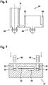
Figur 1 zeigt eine schematische Ansicht einer Einrichtung zum Einspritzen eines in einem Tank gespeicherten Fluids in einen Abgasstrang eines Verbrennungsmotors. -
Figur 2 zeigt eine seitliche Schnittansicht einer Schallführungseinheit gemäße einem Ausführungsbeispiel der Erfindung. -
Figur 3 zeigt eine Draufsicht auf die in derFigur 2 gezeigte Schallführungseinheit. -
Figur 4 veranschaulicht die Verbindung der Messstreckeneinheit mit der Wandlereinheit durch Schweißnähte. -
Figuren 5 bis 7 veranschaulichen die Verbindung der Messstreckeneinheit mit der Wandlereinheit durch Rastverbindungen. -
Figuren 8 und 9 zeigen eine Wandlereinheit und eine Messstreckeneinheit, die gegeneinander verschiebbar miteinander verbunden sind. -
Figur 1 zeigt eine schematische Ansicht eines Abgasreduktionssystems 1 zum Einspritzen eines in einem Tank 2 gespeicherten fluiden Reduktionsmittels 6 (Fluid), insbesondere einer wässrigen Harnstofflösung ("AdBlue"®), in einen Abgasstrang 12 eines Verbrennungsmotors 14, insbesondere eines Dieselmotors 14. - Beim Betrieb des Abgasreduktionssystems 1 wird das Fluid 6 von einem Fördermodul 4, das innerhalb oder außerhalb des Tanks 2 angeordnet sein kann, aus dem Tank 2 entnommen und unter erhöhtem Druck durch eine Druckleitung 8 einer unmittelbar am Abgasstrang 12 positionierten Einspritzvorrichtung 10 zugeführt. Die Einspritzvorrichtung 10 spritzt das Fluid 6 in den Abgasstrang 12 ein, wo es sich mit den durch den Abgasstrang 12 strömenden Abgasen 16 des Verbrennungsmotors 14 vermischt.
- An einem Boden 3 des Tanks 2 ist eine Schallführungseinheit 20 angeordnet, die es ermöglicht, die Füllhöhe des Fluids 6 im Tank 2 und/oder die Qualität des Fluids 6 zu bestimmen.
-
Figur 2 zeigt eine vergrößerte seitliche Schnittansicht der am Boden 3 des Tanks 2 angeordneten Schallführungseinheit 20. -
Figur 3 zeigt eine Draufsicht auf die Schallführungseinheit 20. - Die Schallführungseinheit 20 umfasst eine Wandlereinheit 22 und eine Messstreckeneinheit 24.
- In der Wandlereinheit 22 sind zwei Schallwandler 26, 28 vorgesehen. Die Schallwandler 26, 28 umfassen einen Füllhöhen-Schallwandler 26, der zur Bestimmung der Füllhöhe H des Fluids 6 im Tank 2 vorgesehen ist, und einen Qualitäts-Schallwandler 28, der zur Bestimmung der Qualität des Fluids 6 vorgesehen ist.
- Die beiden Schallwandler 26, 28 können jeweils sowohl als Schallgeber als auch Schallsensor betrieben werden und/oder eine Kombination aus einem Schallgeber und einem Schallsensor umfassen. Die beiden Schallwandler 26, 28 können, müssen aber nicht, baugleich sein und können insbesondere als Piezo-Schallwandler ausgebildet sein.
- Die beiden Schallwandler 26, 28 können von einer gemeinsamen elektrischen oder elektronische Steuerschaltung 30 angesteuert werden, die auf einer Leiterplatte 32 ausgebildet ist, die in/an der Wandlereinheit 22 angeordnet ist. In einem alternativen, nicht in den Figuren gezeigten, Ausführungsbeispiel können die beiden Schallwandler 26, 28 jeweils eine eigenen Steuerschaltung 30 aufweisen sein. Dabei können die Steuerschaltungen 30 der beiden Schallwandler 26, 28 auf einer gemeinsamen oder auf separaten Leiterplatten 32 ausgebildet sein.
- Der Füllhöhen-Schallwandler 26 ist derart ausgebildet und angeordnet, dass er im Betrieb Schall im Wesentlichen in vertikaler Richtung nach oben, d.h. in Richtung der Oberfläche des im Tank 2 gespeicherten Fluids 6 abgibt.
- Der Qualitäts-Schallwandler 28 ist derart ausgebildet und angeordnet, dass er Schall im Wesentlichen in horizontaler Richtung abgibt.
- Die Messstreckeneinheit 24 ist oberhalb der Wandlereinheit 22 angeordnet.
- Die Messstreckeneinheit 24 umfasst insbesondere ein Schallführungsrohr 34, das sich im Wesentlichen in vertikaler Richtung erstreckt und vorzugsweise unmittelbar über dem Füllhöhen-Schallwandler 26 angeordnet ist, so dass sich der von dem Füllhöhen-Schallwandler 26 abgegebene Schall im Wesentlichen innerhalb des Schallführungsrohrs 34 ausbreitet.
- Das Schallführungsrohr 34 ist an seinen beiden Enden offen. Zwischen dem unteren Ende des Schallführungsrohrs 34 und der Wandlereinheit 22 ist ein Spalt 36 ausgebildet, so dass im Tank 2 gespeichertes Fluid 6 in das Schallführungsrohr 34 strömen kann. Der Spalt 36 hat insbesondere eine Spaltbreite b von maximal 3 mm. Die Füllhöhe h des Fluids 6 im Schallführungsrohr 34 ergibt sich daher nach dem Prinzip der kommunizierenden Röhren aus der Füllhöhe H des Fluids 6 im Tank 2.
- Um den von dem Füllhöhen-Schallwandler 26 abgegebenen Schall optimal zu nutzen, entspricht der Innendurchmesser d1 des Schallführungsrohrs 34 im Wesentlichen dem Durchmesser d2 des Füllhöhen-Schallwandlers 26. Die Durchmesser d1 und d2 können insbesondere 10 mm bis 18 mm, insbesondere 12 mm bis 16 mm, insbesondere 14 mm betragen. In anderen Fällen kann der Innendurchmesser d1 des Schallführungsrohrs auch kleiner als 10 mm sein.
- Beim Betrieb des Füllhöhen-Schallwandlers 26 breitet sich der von dem Füllhöhen-Schallwandler 26 abgegebene Schall innerhalb des Fluids 6 im Schallführungsrohr 34 aus und wird an der Oberfläche 38 der Fluidsäule im Schallführungsrohr 34 reflektiert. Der reflektierte Schall wird von dem Füllhöhen-Schallwandler 26 detektiert und aus der Laufzeit des Schallsignals zwischen dem Füllhöhen-Schallwandler 26 und der Oberfläche 38 kann aufgrund der bekannten Schallgeschwindigkeit im Fluid 6 die Füllhöhe h des Fluids 6 im Schallführungsrohr 34 und damit auch die Füllhöhe H des Fluids 6 im Tank 2 bestimmt werden.
- Das Schallführungsrohr 40 ist wenigstens teilweise von einem Heizkörper 40 umgeben.
- Der Heizkörper 40 weist insbesondere eine im Wesentlichen in vertikaler Richtung verlaufende Ausnehmung oder Vertiefung 46 auf, und das Schallführungsrohr 40 ist in die Ausnehmung 46 oder Vertiefung eingebracht, insbesondere so, dass wenigstens der halbe Umfang des Schallführungsrohrs 40 den Heizkörper 40 kontaktiert.
- Der Heizkörper 40 ist aus einem thermisch gut leitenden Material, z.B. Aluminium, gefertigt und thermisch mit Wärme abgebenden Elementen 42 verbunden. Die Wärme abgebenden Elemente 42 können spezielle Heizelemente, z.B. PTC-Heizelemente, oder elektrische / elektronische Elemente, z.B. einer Steuerschaltung, sein, die im Betrieb die gewünschte Wärme abgeben.
- Aufgrund seiner guten thermischen Leitfähigkeit überträgt der Heizkörper 40 die von den Wärme abgebenden Elementen 42 abgegebene Wärme effektiv an das Schallführungsrohr 40, welches die Wärme an das darin befindliche Fluid 6 weitergibt.
- Der Heizkörper 40 ermöglicht auch, gefrorenes Medium in Tank 2, das sich außerhalb des Schallführungsrohres 40 befindet, aufzutauen.
- Der Heizkörper 40 und die auf oder an dem Heizkörper 40 vorhandenen Wärme abgebenden Elemente 42 könne von einer, in den Figuren nicht gezeigten, Schutzschicht 41, beispielsweise einer Kunststoff-Umspritzung oder einem Schrumpfschlauch, umgeben sein, um den Heizkörper 40 und die Wärme abgebenden Elemente 42 vor dem Fluid 6 zu schützen.
- Um eine gute Wärmeübertragung an das Fluid 6 zu ermöglichen, ist auch das Schallführungsrohr 34 aus einem gut Wärme leitenden Material, z.B. Metall, insbesondere Edelstahl, oder einem gut Wärme leitenden Kunststoff gefertigt.
- Ist das Schallführungsrohr 34 wenigstens teilweise aus einem magnetischen Metall gefertigt, können an oder in dem Heizkörper 40 Permanentmagnete 44 vorgesehen sein, die es ermöglichen, das Schallführungsrohr 34 durch ihre magnetische Kraft an dem Heizkörper 40 zu fixieren. Auf diese Weise können auch bei großen, auf die Schallführungseinheit 20 einwirkenden Beschleunigungen (g-Kräften) Bewegungen / Schwingungen des Schallführungsrohrs 34, die unerwünschte Streureflektionen des Schalls zur Folge haben würden, vermieden werden.
- Die erfindungsgemäße Kombination des Schallführungsrohrs 34 mit einem Heizkörper 40 ermöglicht es, das Fluid 6 im Tank 2 und insbesondere innerhalb des Schallführungsrohrs 34 schnell und effektiv aufzutauen bzw. am Einfrieren zu hindern. Dadurch kann die Füllhöhe H des Fluid 4 im Tank 2 nach der Inbetriebnahme des Abgasreduktionssystems 1 schnell bestimmt werden. Auch steht schnell flüssiges Fluid 6 bereit, das in den Abgasstrang 12 des Verbrennungsmotors 14 eingespritzt werden kann.
- Die Messstreckeneinheit 24 umfasst zusätzlich zu dem Schallführungsohr 34 wenigstens einen Reflektor (Hauptreflektor) 52, der es ermöglicht, im Zusammenwirken mit dem Qualitäts-Schallwandler 28 die Qualität des im Tank 2 gespeicherten Fluids 6 zu bestimmen. Da Verunreinigungen des Fluids 6 zu einer Änderung der Schallgeschwindigkeit führen, kann aus der Laufzeit eines Schallsignals entlang einer Messstrecke 58 mit bekannter Länge D0 auf die Qualität des Fluids 6 geschlossen werden.
- Um Messfehler, die auch aus einer Variation der Position der Messstreckeneinheit 24 gegenüber der Wandlereinheit 22 ergeben können, zu vermeiden, weist die Messstreckeneinheit 24 zusätzlich einen Referenzreflektor 54 auf. Die Qualität des Fluids 6 wird aufgrund der Differenz der Laufzeiten zwischen dem Qualitäts-Schallwandler 28 und den beiden Reflektoren 52, 54 bestimmt. Die Distanz D1 zwischen den beiden Reflektoren 52, 54 ist durch die Geometrie der Messstreckeneinheit 24 fest vorgegeben, so dass die Qualität des Fluids 6 unabhängig von der Position der Messstreckeneinheit 24 gegenüber der Wandlereinheit 22 mit hoher Genauigkeit bestimmt werden kann.
- Die beiden Reflektoren 52, 54 sind in horizontaler Richtung zwischen dem Qualitäts-Schallwandler 28 und dem Füllhöhen-Schallwandler 26 angeordnet, so dass das Fluid 6 in der Qualitäts-Schallmessstrecke 58 zusätzlich durch die Abwärme der zwischen dem beiden Schallwandlern 26, 28 in der Wandlereinheit 22 angeordnete Steuerschaltung 30 erwärmt wird.
- Dies kann durch eine auf der Leiterplatte 32 der Steuerschaltung 30 ausgebildete Wärmefalle 56 unterstützt werden, welche die von der Steuerschaltung 30 im Betrieb erzeugte Wärme gezielt zur Qualitäts-Schallmessstrecke 58 leitet. Die von der Steuerschaltung 30 erzeugte Wärme wird auf diese Weise effektiv abgeführt, so dass auf zusätzliche Kühlelemente auf der Leiterplatte 32 und eine aktive Temperaturregelung der Steuerschaltung 30 verzichtet werden kann.
- Zusätzlich zum Fluid 6 im Schallführungsrohr 34 wird so auch das Fluid 6 in der Qualitäts-Schallmessstrecke 58 schnell erwärmt / aufgetaut, so dass die Qualität des Fluids 6 nach der Inbetriebnahme des Abgasreduktionssystems 1 schnell bestimmt werden kann und auch das Fluid 6 in der Qualitäts-Schallmessstrecke 58 als flüssiges Fluid 6 zur Verfügung steht, um in den Abgasstrang 12 des Verbrennungsmotors 14 eingespritzt zu werden.
- Die Messstreckeneinheit 24 kann mit der Wandlereinheit 22 durch Schweißnähte 60, 61 fest verbunden werden. In der
Figur 4 sind zwei mögliche Varianten von Schweißnähten 60, 61 gezeigt. Die Verbindung durch Schweißnähte 60, 61 ist insbesondere vorteilhaft, wenn die Schallwandler 26, 28 einen kleinen Durchmesser d2 haben und/oder hohe Beschleunigungen zu erwarten sind. - Alternativ können die Messstreckeneinheit 24 und die Wandlereinheit 22 durch Rastverbindungen miteinander verbunden werde, wie sie beispielhaft in den
Figuren 5 bis 7 gezeigt sind. - Elastische Rasthaken / Rastnasen 62, die an der Messstreckeneinheit 24 oder der Wandlereinheit 22 ausgebildet sind und die sich beispielsweise in einem Führungskanal 63 bewegen, greifen in korrespondierende Ausnehmungen 64 ein, die an/in der anderen der beiden Einheiten 22, 24 ausgebildet sind.
- Dabei können die Messstreckeneinheit 24 und die Wandlereinheit 22 entweder durch eine horizontale Bewegung (siehe
Figur 5 ), d.h. eine Bewegung parallel zur Qualitäts-Schallmessstrecke 58, oder durch eine vertikale Bewegung (sieheFiguren 6 und 7 ), d.h. eine Bewegung parallel zur Füllhöhen-Schallmessstrecke im Schallführungsrohr 34, miteinander verbunden werden. - Zwischen der Messstreckeneinheit 24 und die Wandlereinheit 22, insbesondere an einem Boden der Messstreckeneinheit 24, der der Wandlereinheit 22 zugewandt ist, können elastische Elemente (Federelemente) 66 vorgesehen sein (siehe
Figur 5 ), welche die Position der Messstreckeneinheit 24 gegenüber der Wandlereinheit 22 in vertikaler Richtung und insbesondere die Breite b des Spalts 36 zwischen der Wandlereinheit 22 und dem unteren Ende des Schallführungsrohrs 34 festlegen. - Die Messstreckeneinheit 24 kann auch in horizontaler Richtung verschiebbar an der Wandlereinheit 22 angebracht sein, wie in den
Figuren 8 und 9 gezeigt. Dies ermöglicht es, dass Schallführungsrohr 34 stets exakt über dem Füllhöhen-Schallwandler 26 anzuordnen und mögliche Fertigungstoleranzen auszugleichen. Die Messstreckeneinheit 24 wird dann in der optimalen Position, z.B. durch Schweißen (sieheFigur 4 ), an der Wandlereinheit 22 fixiert. - Dazu können an wenigstens einer der beiden Einheiten 22, 24 eine oder mehrere Führungsnasen 72 ausgebildet sein, die in wenigstens eine korrespondierende Führungsnut 70 eingreifen, die in/an der anderen der beiden Einheiten 22, 24 ausgebildet ist.
- Die Orientierung der Führungsnut 70, die insbesondere in horizontaler Richtung ausgerichtet ist, gibt die Richtung vor, in der die beiden Einheiten 22, 24 gegeneinander bewegbar sind.
- In dem in den
Figuren 7 und9 gezeigten Ausführungsbeispiel sind die Führungsnasen 72 an der Messstreckeneinheit 24 und die Führungsnute(n) 70 in der Wandlereinheit 22 ausgebildet. Der Fachmann versteht jedoch, dass die Führungsnasen 72 auch an der Wandlereinheit 22 und die Führungsnute(n) 70 auch in der Messstreckeneinheit 24 ausgebildet sein können. - Nicht erfindungsgemäß kann die gezeigte Kombination der Füllhöhen-Schallmessstrecke mit einer Qualitäts-Schallmessstrecke 58 in einer Schallführungseinheit 20 optional werden, und kann eine nicht erfindungsgemäße Kombination eines Schallführungsrohrs 34 mit einem das Schallführungsrohr 34 wenigstens teilweise umgebenden Heizelement 40 auch ohne die Qualitäts-Schallmessstrecke 58 realisiert werden. Ebenso kann das vorteilhafte Beheizen der Qualitäts-Schallmessstrecke 58 durch die Abwärme einer in der Wandlereinheit 22 vorgesehenen Steuerschaltung 30 unabhängig von der Füllhöhen-Schallmessstrecke realisiert werden.
Claims (11)
- Schallführungseinheit (20) für einen Tank (2), der zur Speicherung eines Fluids, insbesondere fluiden Reduktionsmittels, (6) vorgesehen ist, miteiner Wandlereinheit (22) und einer Messstreckeneinheit (24);einer Füllhöhen-Schallmessstrecke, die zur Messung der Füllhöhe (H) des Fluids (6) im Tank (2) ausgebildet ist, wobei die Füllhöhen-Schallmessstrecke ein im Wesentliches in vertikaler Richtung verlaufendes Schallführungsrohr (34) und einen an einem unteren Ende des Schallführungsrohrs (34) angeordneten Füllhöhen-Schallwandler (26) aufweist, wobei der Füllhöhen-Schallwandler (26) in oder an der Wandlereinheit (22) ausgebildet ist, und wobei das Schallführungsrohr (34) in oder an der Messstreckeneinheit (24) ausgebildet ist;wobei die Schallführungseinheit (20) einen Heizkörper (40) aufweist, der an oder um wenigsten einen Bereich des Schallführungsrohrs (34) angeordnet ist;wobei die Schallführungseinheit (20) zusätzlich eine Qualitäts-Schallmessstrecke (58) mit einem an der Qualitäts-Schallmessstrecke (58) angeordneten Qualitäts-Schallwandler (28) und einem an der Qualitäts-Schallmessstrecke (58) angeordneten Hauptreflektor (52) umfasst; undwobei der Hauptreflektor (52) in horizontaler Richtung zwischen dem Qualitäts-Schallwandler (28) und dem Füllhöhen-Schallwandler (26) angeordnet ist, so dass das Fluid (6) in der Qualitäts-Schallmessstrecke (58) durch die Abwärme einer zwischen den beiden Schallwandlern (26, 28) in der Wandlereinheit (22) angeordnete Steuerschaltung (30) erwärmt wird.
- Schallführungseinheit (20) nach Anspruch 1, wobei der Heizkörper (40) wenigstens eine Ausnehmung oder Vertiefung (46) aufweist und wobei der wenigstens eine Bereich des Schallführungsrohrs (34) in der wenigstens einen Ausnehmung (46) oder Vertiefung angeordnet ist.
- Schallführungseinheit (20) nach Anspruch 1 oder 2, wobei das Schallführungsrohr (34) wenigstens teilweise aus Metall ausgebildet ist, und wobei in oder an dem Heizkörper (40) wenigstens ein Magnet (44) vorhanden ist, der es ermöglicht, das Schallführungsrohr (34) durch Magnetkraft an dem Heizkörper (40) zu fixieren.
- Schallführungseinheit (20) nach einem der vorangehenden Ansprüche, wobei das Schallführungsrohr (34) einen Innendurchmesser (d1) von 10 mm bis 18 mm, insbesondere einen Innendurchmesser (d1) von 12 mm bis 16 mm, insbesondere einen Innendurchmesser (d1) von 14 mm hat, oder wobei das Schallführungsrohr (34) einen Innendurchmesser (d1) von weniger als 10 mm hat.
- Schallführungseinheit (20) nach einem der vorangehenden Ansprüche, wobei sich die Qualitäts-Schallmessstrecke (58) im Wesentlichen orthogonal zum Schallführungsrohr (34) erstreckt.
- Schallführungseinheit (20) nach Anspruch 5, wobei Schallführungseinheit (20) einen an der Qualitäts-Schallmessstrecke (58) angeordneten Referenzreflektor (54) umfasst, wobei der Referenzreflektor (54) insbesondere zwischen dem Qualitäts-Schallwandler (28) und dem Hauptreflektor (52) angeordnet ist.
- Schallführungseinheit (20) nach einem der vorangehenden Ansprüche, wobei die Wandlereinheit (22) und die Messstreckeneinheit (24) so ausgebildet sind, dass sie durch eine horizontale Relativbewegung oder durch eine vertikale Relativbewegung miteinander verbindbar sind.
- Schallführungseinheit (20) nach Anspruch 7, wobei wenigstens eine von der Wandlereinheit (22) und der Messstreckeneinheit (24) wenigstens ein Rastelement (62) aufweist, das es ermöglicht, die beiden Einheiten (22, 24) durch Einrasten des wenigstens einen Rastelements (62) mechanisch miteinander zu verbinden.
- Schallführungseinheit (20) nach einem der vorangehenden Ansprüche, wobei wenigstens eine von der Wandlereinheit (22) und der Messstreckeneinheit (24) wenigstens eine Führungsnase (72) aufweist, und wobei die andere von der Wandlereinheit (22) und der Messstreckeneinheit (24) wenigstens eine Führungsnut (70) aufweist, die zur Aufnahme der wenigstens einen Führungsnase (72) ausgebildet ist.
- Tank (2) zur Speicherung eines Fluids (6) mit einer Schallführungseinheit (20) nach einem der vorangehenden Ansprüche.
- Abgasreduktionssystem mit einem Tank (2) zur Speicherung eines Fluids (6) nach Anspruch 10.
Applications Claiming Priority (2)
| Application Number | Priority Date | Filing Date | Title |
|---|---|---|---|
| DE102018202596.7A DE102018202596A1 (de) | 2018-02-21 | 2018-02-21 | Schallführungseinheit und Tank zur Speicherung fluiden Reduktionsmittels |
| PCT/EP2019/051722 WO2019162031A1 (de) | 2018-02-21 | 2019-01-24 | Schallführungseinheit und tank zur speicherung fluiden reduktionsmittels |
Publications (2)
| Publication Number | Publication Date |
|---|---|
| EP3755976A1 EP3755976A1 (de) | 2020-12-30 |
| EP3755976B1 true EP3755976B1 (de) | 2022-03-30 |
Family
ID=65234556
Family Applications (1)
| Application Number | Title | Priority Date | Filing Date |
|---|---|---|---|
| EP19701827.8A Active EP3755976B1 (de) | 2018-02-21 | 2019-01-24 | Schallführungseinheit und tank zur speicherung fluiden reduktionsmittels |
Country Status (5)
| Country | Link |
|---|---|
| EP (1) | EP3755976B1 (de) |
| KR (1) | KR102624746B1 (de) |
| CN (1) | CN111742197B (de) |
| DE (1) | DE102018202596A1 (de) |
| WO (1) | WO2019162031A1 (de) |
Citations (1)
| Publication number | Priority date | Publication date | Assignee | Title |
|---|---|---|---|---|
| US9664552B2 (en) * | 2010-11-11 | 2017-05-30 | Ssi Technologies, Inc. | Systems and methods of determining a quality and a quantity of a fluid |
Family Cites Families (9)
| Publication number | Priority date | Publication date | Assignee | Title |
|---|---|---|---|---|
| EP0965056A4 (de) * | 1997-02-27 | 2001-03-21 | Drexelbrook Controls | Kondensatfreier ultraschallsender |
| DE10312102B4 (de) * | 2003-03-19 | 2015-10-08 | Robert Bosch Gmbh | Vorrichtung zur Messung eines Füllstandes einer Flüssigkeit in einem Behälter |
| DE102011103644B4 (de) * | 2011-06-08 | 2024-09-19 | Mercedes-Benz Group AG | Reduktionsmitteltank und Verfahren zum Erfassen eines Vorhandenseins von flüssigem Reduktionsmittel in einem Reduktionsmitteltank |
| DE102011086774A1 (de) * | 2011-11-22 | 2013-05-23 | Robert Bosch Gmbh | Vorrichtung und Verfahren zur gleichzeitigen Füllstandsbestimmung und Qualitätsbestimmung einer Reduktionsmittellösung |
| CN102865904A (zh) * | 2012-09-04 | 2013-01-09 | 无锡市兰辉超声电子设备厂 | 超声波液位计装置 |
| JP5959402B2 (ja) * | 2012-10-22 | 2016-08-02 | 高砂熱学工業株式会社 | 固定装置、固定方法、及び流量計測装置 |
| US20140311239A1 (en) * | 2013-04-19 | 2014-10-23 | Igor Marjanovic | Hydration Monitor |
| DE102014210077A1 (de) * | 2014-05-27 | 2015-12-03 | Continental Automotive Gmbh | Vorrichtung und Verfahren zum Bestimmen einer Höhe einer Fluidoberfläche in einem Fluidbehälter |
| DE202014103537U1 (de) * | 2014-07-30 | 2015-07-31 | Seuffer gmbH & Co. KG | Sensorvorrichtung zur Erfassung von Eigenschaften fluider Medien |
-
2018
- 2018-02-21 DE DE102018202596.7A patent/DE102018202596A1/de not_active Withdrawn
-
2019
- 2019-01-24 KR KR1020207026567A patent/KR102624746B1/ko active Active
- 2019-01-24 EP EP19701827.8A patent/EP3755976B1/de active Active
- 2019-01-24 CN CN201980014596.1A patent/CN111742197B/zh active Active
- 2019-01-24 WO PCT/EP2019/051722 patent/WO2019162031A1/de not_active Ceased
Patent Citations (1)
| Publication number | Priority date | Publication date | Assignee | Title |
|---|---|---|---|---|
| US9664552B2 (en) * | 2010-11-11 | 2017-05-30 | Ssi Technologies, Inc. | Systems and methods of determining a quality and a quantity of a fluid |
Also Published As
| Publication number | Publication date |
|---|---|
| DE102018202596A1 (de) | 2019-08-22 |
| CN111742197B (zh) | 2024-08-13 |
| CN111742197A (zh) | 2020-10-02 |
| KR102624746B1 (ko) | 2024-01-16 |
| WO2019162031A1 (de) | 2019-08-29 |
| KR20200122340A (ko) | 2020-10-27 |
| EP3755976A1 (de) | 2020-12-30 |
Similar Documents
| Publication | Publication Date | Title |
|---|---|---|
| EP1473447B1 (de) | Flüssigkeitsbehälter für Kraftfahrzeuge, insbesondere für eine wässrige Harnstofflösung | |
| WO2019105774A1 (de) | Ultraschallsensor, tankeinbaueinheit mit einem ultraschallsensor | |
| EP1192337A1 (de) | Ventilaufnahmevorrichtung für ein dosierventil einer abgasnachbehandlungsanlage | |
| DE112014004566T5 (de) | Verringerung belüftungsbedingter Störungen in einem Ultraschallerfassungssystem für ein Fluid | |
| WO2011032709A1 (de) | Heizungsanordnung | |
| DE102007059853A1 (de) | Vorrichtung zur Messung eines Füllstandes einer Flüssigkeit in einem Behälter | |
| DE10312102B4 (de) | Vorrichtung zur Messung eines Füllstandes einer Flüssigkeit in einem Behälter | |
| DE102013108158A1 (de) | Verfahren zur Herstellung eines Tanks mit einem kalibrierten Sensor | |
| DE102011086795A1 (de) | Vorrichtung zur Kühlung eines Dosierventils | |
| DE102006013263A1 (de) | Verfahren zur Bestimmung einer Konzentration eines Bestandteils einer Flüssigkeit in einem Kraftfahrzeug | |
| EP2863215B1 (de) | Sensorvorrichtung zur Erfassung von Eigenschaften fluider Medien | |
| EP3652529B1 (de) | Vorrichtung zum messen der konzentration eines reduktionsmittels | |
| WO2018095838A1 (de) | Vorrichtung zur verdampfung eines fluids | |
| EP3755976B1 (de) | Schallführungseinheit und tank zur speicherung fluiden reduktionsmittels | |
| DE202016004870U1 (de) | Sensoranordnung zum Einbau in einen Fluidtank eines Abgasnachbehandlungssystems | |
| DE102011018482A1 (de) | Medienleitung, insbesondere zum Transport von Harnstoff-Wasser-Lösungen | |
| DE102008042954A1 (de) | Dosiersystem für ein flüssiges Medium, insbesondere Harnstoff-Wasser-Lösung | |
| DE102007022513B4 (de) | Luftmassensensor | |
| WO2020094315A1 (de) | Vorrichtung zur qualitätsbestimmung einer flüssigkeit, tankvorrichtung | |
| DE102014106530B4 (de) | Rohranordnung zur Schallführung | |
| DE202017100663U1 (de) | Sensorvorrichtung zur Erfassung von Eigenschaften fluider Medien | |
| WO2022258316A1 (de) | Beheizbarer behälter zur speicherung eines fluids | |
| DE202014103537U1 (de) | Sensorvorrichtung zur Erfassung von Eigenschaften fluider Medien | |
| WO2019223934A1 (de) | Gassensor mit einer grundgehäuseseitigen umlenkfläche zur drosselung der fluidströmung | |
| DE102018209739A1 (de) | Schallführungseinheit für einen Tank zur Speicherung fluiden Reduktionsmittels |
Legal Events
| Date | Code | Title | Description |
|---|---|---|---|
| STAA | Information on the status of an ep patent application or granted ep patent |
Free format text: STATUS: UNKNOWN |
|
| STAA | Information on the status of an ep patent application or granted ep patent |
Free format text: STATUS: THE INTERNATIONAL PUBLICATION HAS BEEN MADE |
|
| PUAI | Public reference made under article 153(3) epc to a published international application that has entered the european phase |
Free format text: ORIGINAL CODE: 0009012 |
|
| STAA | Information on the status of an ep patent application or granted ep patent |
Free format text: STATUS: REQUEST FOR EXAMINATION WAS MADE |
|
| 17P | Request for examination filed |
Effective date: 20200921 |
|
| AK | Designated contracting states |
Kind code of ref document: A1 Designated state(s): AL AT BE BG CH CY CZ DE DK EE ES FI FR GB GR HR HU IE IS IT LI LT LU LV MC MK MT NL NO PL PT RO RS SE SI SK SM TR |
|
| AX | Request for extension of the european patent |
Extension state: BA ME |
|
| DAV | Request for validation of the european patent (deleted) | ||
| DAX | Request for extension of the european patent (deleted) | ||
| REG | Reference to a national code |
Ref country code: DE Ref legal event code: R079 Ref document number: 502019003867 Country of ref document: DE Free format text: PREVIOUS MAIN CLASS: G01F0023296000 Ipc: B60K0013040000 |
|
| GRAP | Despatch of communication of intention to grant a patent |
Free format text: ORIGINAL CODE: EPIDOSNIGR1 |
|
| STAA | Information on the status of an ep patent application or granted ep patent |
Free format text: STATUS: GRANT OF PATENT IS INTENDED |
|
| RIC1 | Information provided on ipc code assigned before grant |
Ipc: F01N 3/20 20060101ALI20211022BHEP Ipc: G01F 23/296 20060101ALI20211022BHEP Ipc: B60K 15/03 20060101ALI20211022BHEP Ipc: B60K 13/04 20060101AFI20211022BHEP |
|
| INTG | Intention to grant announced |
Effective date: 20211110 |
|
| GRAS | Grant fee paid |
Free format text: ORIGINAL CODE: EPIDOSNIGR3 |
|
| GRAA | (expected) grant |
Free format text: ORIGINAL CODE: 0009210 |
|
| STAA | Information on the status of an ep patent application or granted ep patent |
Free format text: STATUS: THE PATENT HAS BEEN GRANTED |
|
| AK | Designated contracting states |
Kind code of ref document: B1 Designated state(s): AL AT BE BG CH CY CZ DE DK EE ES FI FR GB GR HR HU IE IS IT LI LT LU LV MC MK MT NL NO PL PT RO RS SE SI SK SM TR |
|
| REG | Reference to a national code |
Ref country code: GB Ref legal event code: FG4D Free format text: NOT ENGLISH |
|
| REG | Reference to a national code |
Ref country code: CH Ref legal event code: EP |
|
| REG | Reference to a national code |
Ref country code: DE Ref legal event code: R096 Ref document number: 502019003867 Country of ref document: DE |
|
| REG | Reference to a national code |
Ref country code: AT Ref legal event code: REF Ref document number: 1478870 Country of ref document: AT Kind code of ref document: T Effective date: 20220415 |
|
| REG | Reference to a national code |
Ref country code: IE Ref legal event code: FG4D Free format text: LANGUAGE OF EP DOCUMENT: GERMAN |
|
| REG | Reference to a national code |
Ref country code: LT Ref legal event code: MG9D |
|
| PG25 | Lapsed in a contracting state [announced via postgrant information from national office to epo] |
Ref country code: SE Free format text: LAPSE BECAUSE OF FAILURE TO SUBMIT A TRANSLATION OF THE DESCRIPTION OR TO PAY THE FEE WITHIN THE PRESCRIBED TIME-LIMIT Effective date: 20220330 Ref country code: RS Free format text: LAPSE BECAUSE OF FAILURE TO SUBMIT A TRANSLATION OF THE DESCRIPTION OR TO PAY THE FEE WITHIN THE PRESCRIBED TIME-LIMIT Effective date: 20220330 Ref country code: NO Free format text: LAPSE BECAUSE OF FAILURE TO SUBMIT A TRANSLATION OF THE DESCRIPTION OR TO PAY THE FEE WITHIN THE PRESCRIBED TIME-LIMIT Effective date: 20220630 Ref country code: LT Free format text: LAPSE BECAUSE OF FAILURE TO SUBMIT A TRANSLATION OF THE DESCRIPTION OR TO PAY THE FEE WITHIN THE PRESCRIBED TIME-LIMIT Effective date: 20220330 Ref country code: HR Free format text: LAPSE BECAUSE OF FAILURE TO SUBMIT A TRANSLATION OF THE DESCRIPTION OR TO PAY THE FEE WITHIN THE PRESCRIBED TIME-LIMIT Effective date: 20220330 Ref country code: BG Free format text: LAPSE BECAUSE OF FAILURE TO SUBMIT A TRANSLATION OF THE DESCRIPTION OR TO PAY THE FEE WITHIN THE PRESCRIBED TIME-LIMIT Effective date: 20220630 |
|
| REG | Reference to a national code |
Ref country code: NL Ref legal event code: MP Effective date: 20220330 |
|
| PG25 | Lapsed in a contracting state [announced via postgrant information from national office to epo] |
Ref country code: LV Free format text: LAPSE BECAUSE OF FAILURE TO SUBMIT A TRANSLATION OF THE DESCRIPTION OR TO PAY THE FEE WITHIN THE PRESCRIBED TIME-LIMIT Effective date: 20220330 Ref country code: GR Free format text: LAPSE BECAUSE OF FAILURE TO SUBMIT A TRANSLATION OF THE DESCRIPTION OR TO PAY THE FEE WITHIN THE PRESCRIBED TIME-LIMIT Effective date: 20220701 Ref country code: FI Free format text: LAPSE BECAUSE OF FAILURE TO SUBMIT A TRANSLATION OF THE DESCRIPTION OR TO PAY THE FEE WITHIN THE PRESCRIBED TIME-LIMIT Effective date: 20220330 |
|
| PG25 | Lapsed in a contracting state [announced via postgrant information from national office to epo] |
Ref country code: NL Free format text: LAPSE BECAUSE OF FAILURE TO SUBMIT A TRANSLATION OF THE DESCRIPTION OR TO PAY THE FEE WITHIN THE PRESCRIBED TIME-LIMIT Effective date: 20220330 |
|
| PG25 | Lapsed in a contracting state [announced via postgrant information from national office to epo] |
Ref country code: SM Free format text: LAPSE BECAUSE OF FAILURE TO SUBMIT A TRANSLATION OF THE DESCRIPTION OR TO PAY THE FEE WITHIN THE PRESCRIBED TIME-LIMIT Effective date: 20220330 Ref country code: SK Free format text: LAPSE BECAUSE OF FAILURE TO SUBMIT A TRANSLATION OF THE DESCRIPTION OR TO PAY THE FEE WITHIN THE PRESCRIBED TIME-LIMIT Effective date: 20220330 Ref country code: RO Free format text: LAPSE BECAUSE OF FAILURE TO SUBMIT A TRANSLATION OF THE DESCRIPTION OR TO PAY THE FEE WITHIN THE PRESCRIBED TIME-LIMIT Effective date: 20220330 Ref country code: PT Free format text: LAPSE BECAUSE OF FAILURE TO SUBMIT A TRANSLATION OF THE DESCRIPTION OR TO PAY THE FEE WITHIN THE PRESCRIBED TIME-LIMIT Effective date: 20220801 Ref country code: ES Free format text: LAPSE BECAUSE OF FAILURE TO SUBMIT A TRANSLATION OF THE DESCRIPTION OR TO PAY THE FEE WITHIN THE PRESCRIBED TIME-LIMIT Effective date: 20220330 Ref country code: EE Free format text: LAPSE BECAUSE OF FAILURE TO SUBMIT A TRANSLATION OF THE DESCRIPTION OR TO PAY THE FEE WITHIN THE PRESCRIBED TIME-LIMIT Effective date: 20220330 Ref country code: CZ Free format text: LAPSE BECAUSE OF FAILURE TO SUBMIT A TRANSLATION OF THE DESCRIPTION OR TO PAY THE FEE WITHIN THE PRESCRIBED TIME-LIMIT Effective date: 20220330 |
|
| PG25 | Lapsed in a contracting state [announced via postgrant information from national office to epo] |
Ref country code: PL Free format text: LAPSE BECAUSE OF FAILURE TO SUBMIT A TRANSLATION OF THE DESCRIPTION OR TO PAY THE FEE WITHIN THE PRESCRIBED TIME-LIMIT Effective date: 20220330 Ref country code: IS Free format text: LAPSE BECAUSE OF FAILURE TO SUBMIT A TRANSLATION OF THE DESCRIPTION OR TO PAY THE FEE WITHIN THE PRESCRIBED TIME-LIMIT Effective date: 20220730 Ref country code: AL Free format text: LAPSE BECAUSE OF FAILURE TO SUBMIT A TRANSLATION OF THE DESCRIPTION OR TO PAY THE FEE WITHIN THE PRESCRIBED TIME-LIMIT Effective date: 20220330 |
|
| REG | Reference to a national code |
Ref country code: DE Ref legal event code: R097 Ref document number: 502019003867 Country of ref document: DE |
|
| PG25 | Lapsed in a contracting state [announced via postgrant information from national office to epo] |
Ref country code: DK Free format text: LAPSE BECAUSE OF FAILURE TO SUBMIT A TRANSLATION OF THE DESCRIPTION OR TO PAY THE FEE WITHIN THE PRESCRIBED TIME-LIMIT Effective date: 20220330 |
|
| PLBE | No opposition filed within time limit |
Free format text: ORIGINAL CODE: 0009261 |
|
| STAA | Information on the status of an ep patent application or granted ep patent |
Free format text: STATUS: NO OPPOSITION FILED WITHIN TIME LIMIT |
|
| 26N | No opposition filed |
Effective date: 20230103 |
|
| PG25 | Lapsed in a contracting state [announced via postgrant information from national office to epo] |
Ref country code: SI Free format text: LAPSE BECAUSE OF FAILURE TO SUBMIT A TRANSLATION OF THE DESCRIPTION OR TO PAY THE FEE WITHIN THE PRESCRIBED TIME-LIMIT Effective date: 20220330 |
|
| PG25 | Lapsed in a contracting state [announced via postgrant information from national office to epo] |
Ref country code: IT Free format text: LAPSE BECAUSE OF FAILURE TO SUBMIT A TRANSLATION OF THE DESCRIPTION OR TO PAY THE FEE WITHIN THE PRESCRIBED TIME-LIMIT Effective date: 20220330 |
|
| REG | Reference to a national code |
Ref country code: CH Ref legal event code: PL |
|
| GBPC | Gb: european patent ceased through non-payment of renewal fee |
Effective date: 20230124 |
|
| PG25 | Lapsed in a contracting state [announced via postgrant information from national office to epo] |
Ref country code: LU Free format text: LAPSE BECAUSE OF NON-PAYMENT OF DUE FEES Effective date: 20230124 |
|
| REG | Reference to a national code |
Ref country code: BE Ref legal event code: MM Effective date: 20230131 |
|
| PG25 | Lapsed in a contracting state [announced via postgrant information from national office to epo] |
Ref country code: LI Free format text: LAPSE BECAUSE OF NON-PAYMENT OF DUE FEES Effective date: 20230131 Ref country code: GB Free format text: LAPSE BECAUSE OF NON-PAYMENT OF DUE FEES Effective date: 20230124 Ref country code: CH Free format text: LAPSE BECAUSE OF NON-PAYMENT OF DUE FEES Effective date: 20230131 |
|
| PG25 | Lapsed in a contracting state [announced via postgrant information from national office to epo] |
Ref country code: BE Free format text: LAPSE BECAUSE OF NON-PAYMENT OF DUE FEES Effective date: 20230131 |
|
| PG25 | Lapsed in a contracting state [announced via postgrant information from national office to epo] |
Ref country code: IE Free format text: LAPSE BECAUSE OF NON-PAYMENT OF DUE FEES Effective date: 20230124 |
|
| PG25 | Lapsed in a contracting state [announced via postgrant information from national office to epo] |
Ref country code: MC Free format text: LAPSE BECAUSE OF FAILURE TO SUBMIT A TRANSLATION OF THE DESCRIPTION OR TO PAY THE FEE WITHIN THE PRESCRIBED TIME-LIMIT Effective date: 20220330 |
|
| PG25 | Lapsed in a contracting state [announced via postgrant information from national office to epo] |
Ref country code: MC Free format text: LAPSE BECAUSE OF FAILURE TO SUBMIT A TRANSLATION OF THE DESCRIPTION OR TO PAY THE FEE WITHIN THE PRESCRIBED TIME-LIMIT Effective date: 20220330 |
|
| REG | Reference to a national code |
Ref country code: AT Ref legal event code: MM01 Ref document number: 1478870 Country of ref document: AT Kind code of ref document: T Effective date: 20240124 |
|
| PG25 | Lapsed in a contracting state [announced via postgrant information from national office to epo] |
Ref country code: AT Free format text: LAPSE BECAUSE OF NON-PAYMENT OF DUE FEES Effective date: 20240124 |
|
| PG25 | Lapsed in a contracting state [announced via postgrant information from national office to epo] |
Ref country code: CY Free format text: LAPSE BECAUSE OF FAILURE TO SUBMIT A TRANSLATION OF THE DESCRIPTION OR TO PAY THE FEE WITHIN THE PRESCRIBED TIME-LIMIT; INVALID AB INITIO Effective date: 20190124 |
|
| PG25 | Lapsed in a contracting state [announced via postgrant information from national office to epo] |
Ref country code: HU Free format text: LAPSE BECAUSE OF FAILURE TO SUBMIT A TRANSLATION OF THE DESCRIPTION OR TO PAY THE FEE WITHIN THE PRESCRIBED TIME-LIMIT; INVALID AB INITIO Effective date: 20190124 |
|
| PG25 | Lapsed in a contracting state [announced via postgrant information from national office to epo] |
Ref country code: TR Free format text: LAPSE BECAUSE OF FAILURE TO SUBMIT A TRANSLATION OF THE DESCRIPTION OR TO PAY THE FEE WITHIN THE PRESCRIBED TIME-LIMIT Effective date: 20220330 |
|
| PGFP | Annual fee paid to national office [announced via postgrant information from national office to epo] |
Ref country code: DE Payment date: 20260319 Year of fee payment: 8 |
|
| PGFP | Annual fee paid to national office [announced via postgrant information from national office to epo] |
Ref country code: AT Payment date: 20260410 Year of fee payment: 5 |
|
| PGFP | Annual fee paid to national office [announced via postgrant information from national office to epo] |
Ref country code: FR Payment date: 20260128 Year of fee payment: 8 |