EP3755960B1 - Fluidkühler, wärmetauscher, dichtungsanordungen und systeme die fluidkühler oder wärmetauscher beinhalten und zugeordnete verfahren - Google Patents
Fluidkühler, wärmetauscher, dichtungsanordungen und systeme die fluidkühler oder wärmetauscher beinhalten und zugeordnete verfahren Download PDFInfo
- Publication number
- EP3755960B1 EP3755960B1 EP19742250.4A EP19742250A EP3755960B1 EP 3755960 B1 EP3755960 B1 EP 3755960B1 EP 19742250 A EP19742250 A EP 19742250A EP 3755960 B1 EP3755960 B1 EP 3755960B1
- Authority
- EP
- European Patent Office
- Prior art keywords
- fluid
- tube
- conical coil
- heat exchanger
- fins
- Prior art date
- Legal status (The legal status is an assumption and is not a legal conclusion. Google has not performed a legal analysis and makes no representation as to the accuracy of the status listed.)
- Active
Links
Images


Classifications
-
- F—MECHANICAL ENGINEERING; LIGHTING; HEATING; WEAPONS; BLASTING
- F28—HEAT EXCHANGE IN GENERAL
- F28D—HEAT-EXCHANGE APPARATUS, NOT PROVIDED FOR IN ANOTHER SUBCLASS, IN WHICH THE HEAT-EXCHANGE MEDIA DO NOT COME INTO DIRECT CONTACT
- F28D7/00—Heat-exchange apparatus having stationary tubular conduit assemblies for both heat-exchange media, the media being in contact with different sides of a conduit wall
- F28D7/02—Heat-exchange apparatus having stationary tubular conduit assemblies for both heat-exchange media, the media being in contact with different sides of a conduit wall the conduits being helically coiled
- F28D7/028—Heat-exchange apparatus having stationary tubular conduit assemblies for both heat-exchange media, the media being in contact with different sides of a conduit wall the conduits being helically coiled the conduits of at least one medium being helically coiled, the coils having a conical configuration
-
- F—MECHANICAL ENGINEERING; LIGHTING; HEATING; WEAPONS; BLASTING
- F04—POSITIVE - DISPLACEMENT MACHINES FOR LIQUIDS; PUMPS FOR LIQUIDS OR ELASTIC FLUIDS
- F04B—POSITIVE-DISPLACEMENT MACHINES FOR LIQUIDS; PUMPS
- F04B39/00—Component parts, details, or accessories, of pumps or pumping systems specially adapted for elastic fluids, not otherwise provided for in, or of interest apart from, groups F04B25/00 - F04B37/00
- F04B39/06—Cooling; Heating; Prevention of freezing
-
- F—MECHANICAL ENGINEERING; LIGHTING; HEATING; WEAPONS; BLASTING
- F04—POSITIVE - DISPLACEMENT MACHINES FOR LIQUIDS; PUMPS FOR LIQUIDS OR ELASTIC FLUIDS
- F04D—NON-POSITIVE-DISPLACEMENT PUMPS
- F04D29/00—Details, component parts, or accessories
- F04D29/08—Sealings
- F04D29/10—Shaft sealings
- F04D29/12—Shaft sealings using sealing-rings
- F04D29/126—Shaft sealings using sealing-rings especially adapted for liquid pumps
- F04D29/128—Shaft sealings using sealing-rings especially adapted for liquid pumps with special means for adducting cooling or sealing fluid
-
- F—MECHANICAL ENGINEERING; LIGHTING; HEATING; WEAPONS; BLASTING
- F16—ENGINEERING ELEMENTS AND UNITS; GENERAL MEASURES FOR PRODUCING AND MAINTAINING EFFECTIVE FUNCTIONING OF MACHINES OR INSTALLATIONS; THERMAL INSULATION IN GENERAL
- F16J—PISTONS; CYLINDERS; SEALINGS
- F16J15/00—Sealings
- F16J15/16—Sealings between relatively-moving surfaces
- F16J15/162—Special parts or details relating to lubrication or cooling of the sealing itself
-
- F—MECHANICAL ENGINEERING; LIGHTING; HEATING; WEAPONS; BLASTING
- F28—HEAT EXCHANGE IN GENERAL
- F28D—HEAT-EXCHANGE APPARATUS, NOT PROVIDED FOR IN ANOTHER SUBCLASS, IN WHICH THE HEAT-EXCHANGE MEDIA DO NOT COME INTO DIRECT CONTACT
- F28D1/00—Heat-exchange apparatus having stationary conduit assemblies for one heat-exchange medium only, the media being in contact with different sides of the conduit wall, in which the other heat-exchange medium is a large body of fluid, e.g. domestic or motor car radiators
- F28D1/02—Heat-exchange apparatus having stationary conduit assemblies for one heat-exchange medium only, the media being in contact with different sides of the conduit wall, in which the other heat-exchange medium is a large body of fluid, e.g. domestic or motor car radiators with heat-exchange conduits immersed in the body of fluid
- F28D1/04—Heat-exchange apparatus having stationary conduit assemblies for one heat-exchange medium only, the media being in contact with different sides of the conduit wall, in which the other heat-exchange medium is a large body of fluid, e.g. domestic or motor car radiators with heat-exchange conduits immersed in the body of fluid with tubular conduits
- F28D1/047—Heat-exchange apparatus having stationary conduit assemblies for one heat-exchange medium only, the media being in contact with different sides of the conduit wall, in which the other heat-exchange medium is a large body of fluid, e.g. domestic or motor car radiators with heat-exchange conduits immersed in the body of fluid with tubular conduits the conduits being bent, e.g. in a serpentine or zig-zag
- F28D1/0472—Heat-exchange apparatus having stationary conduit assemblies for one heat-exchange medium only, the media being in contact with different sides of the conduit wall, in which the other heat-exchange medium is a large body of fluid, e.g. domestic or motor car radiators with heat-exchange conduits immersed in the body of fluid with tubular conduits the conduits being bent, e.g. in a serpentine or zig-zag the conduits being helically or spirally coiled
-
- F—MECHANICAL ENGINEERING; LIGHTING; HEATING; WEAPONS; BLASTING
- F28—HEAT EXCHANGE IN GENERAL
- F28F—DETAILS OF HEAT-EXCHANGE AND HEAT-TRANSFER APPARATUS, OF GENERAL APPLICATION
- F28F1/00—Tubular elements; Assemblies of tubular elements
- F28F1/10—Tubular elements and assemblies thereof with means for increasing heat-transfer area, e.g. with fins, with projections, with recesses
- F28F1/12—Tubular elements and assemblies thereof with means for increasing heat-transfer area, e.g. with fins, with projections, with recesses the means being only outside the tubular element
- F28F1/34—Tubular elements and assemblies thereof with means for increasing heat-transfer area, e.g. with fins, with projections, with recesses the means being only outside the tubular element and extending obliquely
- F28F1/36—Tubular elements and assemblies thereof with means for increasing heat-transfer area, e.g. with fins, with projections, with recesses the means being only outside the tubular element and extending obliquely the means being helically wound fins or wire spirals
-
- F—MECHANICAL ENGINEERING; LIGHTING; HEATING; WEAPONS; BLASTING
- F28—HEAT EXCHANGE IN GENERAL
- F28F—DETAILS OF HEAT-EXCHANGE AND HEAT-TRANSFER APPARATUS, OF GENERAL APPLICATION
- F28F1/00—Tubular elements; Assemblies of tubular elements
- F28F1/10—Tubular elements and assemblies thereof with means for increasing heat-transfer area, e.g. with fins, with projections, with recesses
- F28F1/40—Tubular elements and assemblies thereof with means for increasing heat-transfer area, e.g. with fins, with projections, with recesses the means being only inside the tubular element
Definitions
- Embodiments of the disclosure relate generally to fluid coolers and/or heat exchangers and related systems and methods. Specifically, some embodiments of the disclosure relate to air cooled fluid coolers and heat exchangers for seal assemblies and systems and related methods.
- Fluid heat exchangers or coolers operate on a general principal of maintaining two fluids separate from each other with a thermally conductive material, such as metal, connecting the two fluids.
- the fluids may be in a liquid or gaseous form, depending on the application. Heat is then transferred from the higher temperature fluid to the lower temperature fluid across the thermally conductive material, cooling the higher temperature fluid and warming the lower temperature fluid.
- U.S. Patent 6,076,597 describes a liquid to liquid heat exchanger wherein a tube formed in a coil, with a working fluid flowing through the tube, is immersed in a cooling fluid.
- the tube is formed from a thermally conductive material and provides for the transfer of heat from the working fluid to the cooling fluid.
- U.S. Patent 3,802,499 describes a pipe formed in a helical coil within a casing.
- the pipe has external fins that extend perpendicular to the axis of the pipe.
- the cooling fluid is passed by the pipe in a direction parallel to the fins.
- the fins provide additional surface area of the thermally conductive material to provide additional heat transfer between the two fluids.
- Heat exchangers may be used for removing heat from numerous processes. Some processes that utilize heat exchangers are, for example, air conditioning systems, industrial processes, internal combustion engines, industrial pumps, refrigeration systems, etc. Generally these systems utilize a cooling fluid to transfer heat generated by the process to the heat exchanger. The heat exchanger then transfers the heat from the cooling fluid to a second fluid through the heat exchanger. In many instances the second fluid is ambient air. In some processes, the second fluid may be allowed to passively move across the heat exchanger through naturally occurring wind or natural convection where a flow is induced by adding heat to the secondary fluid. In other processes, the secondary fluid may be mechanically forced across the heat exchanger using, for example, a fan, or a pump.
- a heat exchanger according to the preamble of claim 1 is known from document US 3 612 004 A .
- the invention is defined by a fluid heat exchanger according to claim 1 and a method of cooling a fluid according to claim 12. Further embodiments are described by the dependent claims.
- the term "substantially” or “about” in reference to a given parameter means and includes to a degree that one skilled in the art would understand that the given parameter, property, or condition is met with a small degree of variance, such as within acceptable manufacturing tolerances.
- a parameter that is substantially met may be at least about 90% met, at least about 95% met, at least about 99% met, or even 100% met.
- fluid may mean and include fluids of any type and composition. Fluids may take a liquid form, a gaseous form, or combinations thereof, and, in some instances, may include some solid material. In some embodiments, fluids may convert between a liquid form and a gaseous form during a cooling or heating process as described herein.
- Embodiments of the present disclosure may relate to heat exchangers for use in cooling or heating one fluid with another fluid, for example, without mixing the two fluids.
- heat exchangers or fluid coolers may be implemented with fluid management assemblies and systems, such as, for example, sealing assemblies, valve assemblies, pumps, etc. to assist in dissipating heat energy from such assemblies and systems.
- Embodiments of the present disclosure may include fluid to fluid heat exchangers (e.g., fluid coolers, waste heat recovery units, radiators, evaporators, etc. ) that operate by transferring heat from one fluid to another fluid through a thermally conductive material.
- the transfer of heat in such exchangers may be enhanced by increasing the surface area of the thermally conductive material in contact with each fluid.
- the increase in surface area may be achieved in several different ways.
- Such heat exchangers may accomplish the increase in surface area by increasing the length or number of tubes (e.g ., pipes, passages, channels, etc. ) through which the fluids pass.
- tubes e.g ., pipes, passages, channels, etc.
- multiple tubes may be used within one shell providing substantially more surface area in contact with each fluid.
- Such heat exchangers also accomplish the increased surface area through the use of fins attached to the tubes or passages through which one of the fluids passes.
- the fins transfer heat to or from the tube, which, in turn, transfers the heat to or from the fluid within the tube.
- the fins increase the surface area in contact with a fluid residing on the exterior of the tube.
- FIG. 1 demonstrates an embodiment of a tube 102 ( e.g. , pipe, hose, conduit, passage, etc .) of a heat exchanger.
- the tube 102 may have fins 104 ( e.g ., plates) protruding from the tube 102.
- the fins 104 may be spaced substantially evenly ( e.g ., at substantially common intervals) along the length of the tube 102.
- the fins 104 may be spaced at intervals between about 1 mm and about 8 mm, where the interval is measured from the center of each fin 104.
- the fins 104 may be spaced between about 3 mm and about 6 mm, or between about 4 mm and about 5 mm.
- the fins 104 may be spaced at small intervals to generate more surface area. In other embodiments, the fins 104 may be spaced at larger intervals to enable fluids with higher viscosities to travel between the fins 104. In some embodiments, the presence of natural airflow (e.g ., wind, stack effect, etc. ) may allow for smaller intervals between the fins.
- natural airflow e.g ., wind, stack effect, etc.
- the fins 104 may have a spiral configuration extending around the tube 102, where a middle section between two adjacent fins 104 may directly contact an outer surface of the tube 102 ( e.g ., to assist with heat transfer).
- the fins 104 may have a substantially annular (e.g ., circular) shape.
- the fins 104 may be formed from an elongate strip of material wound around the tube 102 to form the substantially annular shape in a spiral configuration.
- the fins 104 may have other shapes and configurations (e.g. , a quadrilateral shape, a polygonal shape, a non-winding shape, the shapes and configurations discussed below, combinations thereof, etc. ) .
- a first fluid 106 (e.g ., working fluid, treated fluid, closed loop fluid, cooling fluid, etc. ) may flow within the tube and a second fluid 108 (e.g ., secondary cooling fluid, ambient fluid, renewable fluid, air, open loop fluid, etc .) may flow or reside along the exterior of the tube 102 and/or the fins 104.
- the second fluid 108 may be provided in a passive and/or active manner.
- the first fluid 106 flowing in the tube 102 may carry residual heat from a process, such as, for example, a refrigerant process, a combustion process, a seal lubrication system, industrial processes, etc.
- the first fluid 106 may transfer heat (e.g ., heat energy) to the tube 102 as the first fluid 106 travels through the tube 102.
- the tube 102 may, in turn, transfer the heat from the first fluid 106 to the second fluid 108 through an exterior surface of the tube 102 and the fins 104.
- the amount of heat energy capable of being transferred from the first fluid 106 to the second fluid 108 will also increase depending on process conditions.
- the length required to expel the required amount of heat can become prohibitive.
- Some systems require a length of between 1 meter and 10 meters. These lengths in a straight pipe can be prohibitive given space and maintenance requirements in many applications. For example, in industrial applications space for equipment is often limited because of the amount of equipment and the limited space in the area where the equipment is located.
- the pipe may be positioned vertically to reduce the floor space; however, this may result in instrumentation and controls that cannot be reached without the aid of a ladder, scaffold, or other accessibility tool.
- the tube 102 may be formed into a non-linear shape to reduce the amount of space consumed by the heat exchanger while maintaining the additional length.
- the tube 102 may weave back and forth, such as the tubes in a fin plate heat exchanger (e.g ., automotive radiator, hot water heating coil, cold water cooling coil, etc. ) .
- a fin plate heat exchanger e.g ., automotive radiator, hot water heating coil, cold water cooling coil, etc.
- additional factors begin to affect the efficiency of the heat exchanger.
- the additional back pressure may be desirable for reducing the flow and extending the amount of time the fluid spends within the heat exchanger.
- the additional back pressure may create additional problems.
- the fins 104 are often in direct contact with each other or may be a single fin 104 contacting the tube 102 in multiple places and therefore transfer heat between different portions of the tube 102.
- fin plate exchangers often require forced flow of the second fluid 108 through the fin plate exchanger to efficiently transfer heat from the first fluid 106 to the second fluid 108.
- the tube 102 may be formed into stacked rings, such as, for example, a curve, spiral, looped, concentric, or helical coil.
- the helical coil eliminates the sharp bends present in the fin plate.
- additional factors may still affect the efficiency of the heat exchangers in both a fin plate heat exchanger and a helical coil.
- the rings may be stacked one above the next.
- the heat may dissipate upwards through the second fluid 108 toward the next or adjacent ring in the stack thereby heating the adjacent ring and reducing the amount of heat that can be dissipated from the portion of the tube 102 that defines that ring.
- the heat transfers up through the second fluid, eventually a point is reached where the temperature difference between the second fluid and the first fluid is not sufficient to maintain efficient heat transfer between the two fluids.
- FIG. 2 illustrates an embodiment of a fluid heat exchanger 200.
- the fluid heat exchanger may include a pipe 202 with fins 204 extending radially outward from the surface of the pipe 202, which may include similar features, such as the fin configurations, of one or more of the pipes or tubes discussed herein.
- the pipe 202 may include pipe connections 216 ( e.g ., coupling, union, dielectric union, nipple, bushing, double-tapped bushing, flanged connection, compression fittings, etc. ) on the ends of the pipe for connection into a fluid cooling system ( see FIGS. 5 and 6 ). As depicted, the pipe connections 216 may be positioned at opposing ends of the fluid heat exchanger 200.
- the pipe connections 216 may be positioned on one end, side, or even middle portion of the fluid heat exchanger 200 where at least a portion of the pipe 202 may extend from a first pipe connection 216 and double back ( e.g ., return by traversing substantially the same route, for example, in a substantially parallel manner) to a second pipe connection 216 positioned proximate ( e.g ., adjacent) the first pipe connection 216.
- the pipe 202 may define a plurality of stacked rings 210 ( e.g., loops, hoops, etc. ) .
- the plurality of stacked rings 210 may include one or more rings that exhibit differing dimensions from the adjacent stacked rings 210 ( e.g. , at least some of the stacked rings 210 are offset from an adjacent stacked ring 210).
- at least some of the stacked rings 210 may be offset from an adjacent stacked ring 210 ( e.g. , in a lateral direction transverse to a longitudinal axis or centerline of the fluid heat exchanger 200, where the stacked rings 210 extend around the longitudinal axis).
- the plurality of stacked rings 210 may be formed in a curved or annular (e.g ., circular) shape with a gradually increasing or decreasing diameter, such that the plurality of stacked rings 210 defines a conical shape (e.g. , conical coil, conical helix, conical spiral, etc. ) . Decreasing the diameters of the plurality of stacked rings 210 may increase the efficiency of the heat exchanger by decreasing the likelihood that heat energy will transfer in an unintended or undesirable manner between adjacent stacked rings 210 rather than transferring to the surrounding environment.
- a conical shape e.g. , conical coil, conical helix, conical spiral, etc.
- the stacked rings 210 may have a different shape (e.g ., annular, oval, rectangular, polygonal, quadrilateral, square, triangular, hexagonal, etc. ) .
- the differing dimension may be, for example, the length of a side, altitude, diagonal, apothem, radius, etc.
- the stacked rings 210 may exhibit other shapes where the adjacent rings are still at least partially offset from one another.
- the diameters of the rings e.g., rings 212, 213, 214
- the stacked rings 210 may allow significantly longer pipes to be used in a confined space.
- the pipe 202 may be between about 4 meters and 15 meters in length, such as, for example, between about 6 meters and 12 meters.
- the dimensions of the fluid heat exchanger 200 may be, for example, less than 1 meter in height and less than 0.5 meters in diameter.
- the stacked rings 210 may be formed in a conical shape with an apex angle (e.g ., the angle between two lines tangential to the stacked rings 210 converging on a central axis of the conical stack) between about 10° and about 90°, such as between about 15° and about 50°, or about 20° and about 30°.
- a ratio of the spacing between the individual rings within the stacked rings 210 and the change in diameter of the rings 210 may be between about 1:1 and about 12:1, such as between about 5:1 and about 10:1, or about 7:1, where the first number is the spacing and the second number is the change in diameter.
- the pipe 202 may have a diameter between about 8 mm and about 84 mm, such as between about 15 mm and about 25 mm, or about 19 mm.
- a thickness of the pipe 202 may be between about 1 mm and about 5 mm, such as between about 2.5 mm and about 4 mm.
- the fins 204 may extend a height from the pipe 202 that is less than the diameter of the pipe 202.
- the fins may extend a height of between about 2 mm and about 20 mm, such as between about 7 mm and about 12 mm, or about 10 mm.
- the pipe 202 may be formed from a thermally conductive material.
- the pipe 202 may be formed from copper, aluminum, stainless steel, carbon steel, bronze, brass, titanium, or other metal alloys.
- the pipe 202 may be formed from corrosion resistant materials that are also thermally conductive, such as, for example, stainless steel, chrome, nickel, iron, copper, tungsten, and titanium.
- the fins 204 may be formed from a thermally conductive material.
- the fins 204 may be formed from copper, aluminum, stainless steel, carbon steel, bronze, brass, titanium, or other metal alloys.
- the fins 204 may be formed from the same material as the pipe 202.
- the fins 204 may be formed from a different material from the pipe 202.
- the fins 204 may be formed as part of the pipe 202, such as by extrusion, molding, rolling, etc.
- the fins 204 may be formed separately from the pipe 202 and attached thereto.
- the fins 204 may be attached through a process of, for example, soldering, welding ( e.g ., arc welding, laser welding, electric resistance welding, oxy-fuel welding, etc. ), brazing, adhesives, etc.
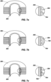
- FIGS. 7a through 7e illustrate pipe and fin configuration in accordance with some embodiments of the disclosure.
- the fins 204 may include an interface surface 704 (e.g. , flange) that may define the spacing between the fins 204, as shown in FIG. 7a .
- the interface surface 704 may extend substantially perpendicular from the fin 204 forming a substantially flat surface to interface with a surface of the pipe 202.
- the interface surface 704 may include an interlocking shelf 706, as shown in FIG. 7b .
- the interlocking shelf 706 may secure the fin 204 to an adjacent fin 204. As depicted, the interlocking shelf 706 may allow the fins 204 to support and/or secure the other adjacent fins 204.
- the pipe may include a discontinuous feature (e.g ., a knurled surface 708), as shown in FIG. 7c .
- the knurled surface 708 may interface with the interface surface 704 of the fins 204.
- the knurled surface 708 may secure the interface surface 704 substantially limiting or preventing lateral motion along the surface of the pipe.
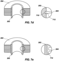
- the interface between the fins 204 and the pipe 202 may a tongue and groove interface (e.g ., half lap joint, dovetail joint,) as shown in FIG. 7d .
- the pipe 202 may include a groove 710.
- the fins 204 may include a complementary base 712 (e.g. , tongue, tenon) that may fit within the groove 710.
- the complementary base 712 may be secured within the groove 710 by an interference fit (e.g ., compression fit, press fit, friction fit).
- the complementary base 712 and the groove 710 may be a loose fit, wherein the groove 710 may substantially prevent lateral motion along the surface of the pipe 202, while allowing motion within ( e.g ., along) the groove 710 to facilitate heat expansion and accommodate different rates of expansion, etc.
- the fins 204 may be extruded or rolled from the pipe 202.
- the fins 204 may be extruded or rolled from a separate sleeve material 714 (e.g. , a continuous material) within which the pipe may be inserted, as shown in FIG. 7e .
- the interface between the pipe 202 and the sleeve material 714 may be an interference fit.
- the interface between the pipe 202 and the sleeve material 714 may include knurled surfaces on at least one of a surface of the pipe 202 or a surface of the sleeve material 714.
- FIG. 3 illustrates a temperature profile of the fluid heat exchanger 200.
- a first fluid 206 may flow within the pipe 202.
- a second fluid 208 may be provided on the exterior of the pipe 202.
- the second fluid 208 may be ambient air.
- the second fluid 208 may be another fluid, such as, for example, water, oil, or other coolants.
- the plurality of stacked rings 210 may be arranged such that the conical shape is substantially vertical.
- the largest ring 212 may be located on the bottom and the smallest ring 214 may be located on the top of the conical shape ( e.g ., in the vertical orientation as shown in FIG. 3 ).
- the conical shape may be inverted with the largest ring 212 on the top of the conical shape and the smallest ring 214 on the bottom of the conical shape.
- the conical shape may include repeating the above configuration in a stacked manner.
- the first fluid 206 may carry heat energy from another process.
- the heat energy of the first fluid 206 may induce a flow on the second fluid 208 through natural or passive convection.
- the second fluid 208 may enter at the bottom of the conical shape as a cool fluid 208a.
- the cool fluid 208a may transition to a warm fluid 208b (e.g ., a warmer fluid 208b having a temperature greater than the cool fluid 208a), which has a lower density than the cool fluid 208a and will generally move in an upward direction relative to the cool fluid 208a.
- the upward movement of the warm fluid 208b may create a natural flow through the conical shape.
- the warm fluid 208b will naturally move from the inside of the conical shape to the outside of the conical shape and continue upwards. This movement may create a low pressure volume inside the conical shape that will, in turn, draw the cool fluid 208a through the bottom of the conical shape to replace the fluid that transitioned to warm fluid 208b.
- the conical or otherwise offset shape may reduce the effect of the lower rings of the plurality of stacked rings 210 on the upper rings of the plurality of stacked rings 210 ( e.g. , to reduce the heating effects of the lower rings on upper rings that are adjacent to one or more of the lower rings).
- the natural convection may induce a flow (e.g. , an at least partially lateral flow) in the second fluid 208 from the inside of the conical shape to the outside of the conical shape through the spaces between the plurality of rings 210 rather than from a top surface of a lower ring to a bottom surface of an upper ring.
- the induced flow may remove heat from both the upper ring and the lower ring at a substantially similar rate because the cool fluid 208a may be a substantially uniform temperature throughout the inside portion of the conical shape and the cool fluid 208a may be drawn through the spaces between the plurality of rings 210 at a substantially uniform rate.
- FIG. 4 illustrates an embodiment of a heat exchanger 300.
- the heat exchanger 300 may include a plurality of tubes 302 (e.g ., two, three, four, five, or more tubes 302, which may include similar features, such as the fin configurations, of one or more of the pipes or tubes discussed herein).
- the heat exchanger 300 may include a first tube 302a and a second tube 302b.
- the tubes 302 may include fins 304 along the length of each of the tubes 302.
- the tubes 302 may define a plurality of rings 310.
- the rings 310 may alternate with one ring defined with the first tube 302a and the next ring defined with the second tube 302b.
- the first and second tubes 302a, 302b may define a conical structure by extending side by side in a substantially parallel manner along a coiled path.
- a first ring 312 defined with the first tube 302a may have the largest diameter of the plurality of rings 310.
- the second ring 313 defined with the second tube 302b may be the same diameter as the first ring 312.
- the second ring 313 may have a smaller diameter than the first ring 312.
- a third ring 314 defined with the first tube 302a may have a diameter smaller than both the first ring 312 and the second ring 313.
- Such a pattern of offset rings 310 may continue along a length or longitudinal axis of the heat exchanger 300.
- the plurality of tubes 302 may be connected at a first manifold 320 and a second manifold 322.
- the first manifold 320 and the second manifold 322 may create a common passageway between the tubes 302 enabling the plurality of tubes 302 to operate in parallel.
- parallel operation may reduce backpressure caused by the heat exchanger 300 by reducing the actual length of the curved tubes 302. A reduction in back pressure may enable the use of tubes 302 having a smaller diameter for increased heat transfer.
- parallel operation may result in a long effective length of the plurality of tubes 302 with a shorter actual length of the tubes 302a, 302b. For example, if the individual tubes 302a, 302b are each 6 meters in length, the effective length of the heat exchanger may be about 12 meters.
- tubes 302a, 302b exhibit a substantially parallel configuration with common pipe connections 316
- the tubes 302a, 302b may be otherwise entwined together ( e.g ., with separate pipe connections, twisted in an overlapping configuration, with mirrored spiral configurations, etc.).
- the individual tubes 302a, 302b may be isolated from each other.
- the first tube 302a may be connected to a first fluid source and the second tube 302b may be connected to a second fluid source.
- the first fluid source and the second fluid source may be connected to the same fluid reservoir or heat source.
- the first fluid source and the second fluid source may be connected to separate fluid reservoirs or heat sources of the same system.
- the first fluid source and the second fluid source may be connected to different systems that are routed to a common location of the heat exchanger 300 ( e.g ., while entering or exiting the heat exchanger 300) for other reasons, such as environmental conditions or space considerations.
- FIG. 5 illustrates an embodiment of a heat exchanger 400 as part of a fluid cooling system 450.
- the tube 402 of the heat exchanger 400 includes fins 404 along substantially the entire length of a tube 402, which may include similar features, such as the fin configurations, of one or more of the pipes or tubes discussed herein.
- the tube 402 may define a series of loops 410 of decreasing/increasing diameter.
- the fluid cooling system 450 may include a frame 452.
- the fluid cooling system 450 may include a top connection point 454 (e.g. , flange, bracket, support, etc. ) that may connect to the top loop 414 of the heat exchanger 400.
- the fluid cooling system 450 may include a bottom connection point 456 that may connect to the bottom loop 412 of the heat exchanger.
- the series of loops 410 may be configured ( e.g ., mounted on the frame 452) to move and absorb some vibration and shock from equipment movement and operation.
- additional connection points may connect the frame to the heat exchanger at additional loops within the series of loops 410 to limit the movement of the series of loops to prevent fatigue failure of the heat exchanger.
- a vent 458 may be located at a high point (e.g. , uppermost point, top, etc. ) on the heat exchanger 400.
- the vent 458 may include a vent valve 460 and a vent pipe 462.
- the vent valve 460 may be opened to bleed air from the fluid cooling system 450 through the vent pipe 462.
- a drain 464 may be located at a low point (e.g ., lowermost point, bottom, etc. ) on the heat exchanger 400.
- the drain 464 may include a drain valve 466 and a drain pipe 468.
- the drain valve 466 may be opened to remove fluid from the fluid cooling system 450 for maintenance, repairs, or removal.
- the fluid cooling system 450 may include an expansion tank 406 (e.g ., bladder, diaphragm, etc. ) to accommodate volume changes of the cooling fluid as the temperature of the cooling fluid changes.
- an expansion tank 406 e.g ., bladder, diaphragm, etc.
- some embodiments may include a plurality of tubes 302 and manifolds 320, 322 connecting the plurality of tubes 302.
- a vent 360 may be included in the top manifold 322 and/or a drain 364 may be included in the bottom manifold 320.
- the vent 360 may be a spring valve, a bleed screw, a bleed port, a plug, or a vent pipe and valve combination.
- a drain 364 may be included in the bottom manifold 320.
- the drain 364 may be a spring valve, a bleed screw, a bleed port, a plug, or a drain pipe and valve combination.
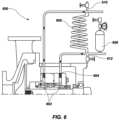
- FIG. 6 illustrates a schematic of a fluid cooling system 600.
- a fluid cooling system may be connected to a mechanical or pump seal 602 (e.g ., shaft seal, dual seals, dual pressurized seals, etc. ) .
- Pump seals 602 generate significant amounts of heat when a pump is in operation.
- a pump seal 602 may include a pump ring 604 ( e.g. , radial flow pumping ring or axial flow pumping ring) for moving a cooling fluid through the pump seals 602 for a fluid flush of the pump seal 602.
- a fluid flush of the pump seal 602 may remove heat from the pump seal 602 and may also lubricate the pump seal 602.
- the fluid cooling system 600 may be a closed loop system.
- a closed loop system may be necessary, for example, when the cooling fluid is hazardous or toxic, has high vapor pressure, has special additives (e.g ., glycol, scale preventers, etc. ), and/or the pumped fluid is not conducive to cooling and/or lubricating seals ( e.g. , dirty, abrasive, or polymerizing fluids).
- the cooling fluid may be completely isolated from the pumped fluid.
- the closed loop system may include an expansion tank 606 (e.g ., bladder, diaphragm, etc. ) to accommodate volume changes of the cooling fluid as the temperature of the cooling fluid changes.
- the fluid cooling system 600 may include a conical coil 608 (e.g., similar to those discussed herein) for removing heat from the system (e.g ., from the cooling fluid as it passes through the conical coil 608).
- the fluid cooling system 600 may also include a vent 610 and a drain 612 for removing and adding fluid to the system for maintenance, repair, or replacement processes.
- the embodiments of the present disclosure may provide more efficient passive heat exchanger systems, where implemented.
- the embodiments may induce natural convective flow in a secondary cooling medium to remove heat more efficiently.
- Passive heat exchangers may provide additional cost saving benefits because of the reduced amount of hardware required and the reduced amount of moving parts that require maintenance.
- Some embodiments may increase the effective length of the heat exchanger while maintaining easy access to any instrumentation and controls that may be present on the top and bottom of the heat exchanger.
- the increased effective length may increase the efficiency of the heat exchanger, while the compact design may provide space saving benefits in industries where floor space is a premium commodity.
Landscapes
- Engineering & Computer Science (AREA)
- Physics & Mathematics (AREA)
- General Engineering & Computer Science (AREA)
- Mechanical Engineering (AREA)
- Thermal Sciences (AREA)
- Geometry (AREA)
- Heat-Exchange Devices With Radiators And Conduit Assemblies (AREA)
Claims (14)
- Fluidwärmetauscher (100, 200, 300, 400), umfassend:ein erstes Rohr (102, 202, 302, 402), das eine im Wesentlichen konische Spule definiert, wobei sich das erste Rohr (102, 202, 302, 402) um eine Längsachse des Fluidwärmetauschers (100, 200, 300, 400) herum erstreckt, wobei das erste Rohr (102, 202, 302, 402) mindestens einen bogenförmigen Teil aufweist, der von einem anderen bogenförmigen Teil des ersten Rohrs (102, 202, 302, 402) in einer Richtung quer zu der Längsachse seitlich versetzt ist;eine Vielzahl von Rippen (104, 204, 304, 404), die an einer Außenoberfläche des ersten Rohrs (102, 202, 302, 402) angebracht sind;mindestens ein Anschlussstück (216, 316), das mit dem ersten Rohr (102, 202, 302, 402) gekoppelt ist, um eine Fluidströmung in und aus dem ersten Rohr (102, 202, 302, 402) zu ermöglichen, um Wärmeenergie zwischen einem ersten Fluid innerhalb des ersten Rohrs (102, 202, 302, 402) und einem zweiten Fluid an einer Außenseite des ersten Rohrs (102, 202, 302, 402) in der Nähe des ersten Rohrs (102, 202, 302, 402) und der Vielzahl von Rippen (104, 204, 304, 404) zu übertragen; unddadurch gekennzeichnet, dass die im Wesentlichen konische Spule durch eine Vielzahl von Ringen (210, 310, 410) definiert ist, die Räume zwischen der Vielzahl von Ringen (210, 310, 410) der im Wesentlichen konischen Spule einschließen; undein zweites Rohr (102, 202, 302, 402), das die im Wesentlichen konische Spule definiert, wobei sich das erste Rohr (102, 202, 302, 402) und das zweite Rohr (102, 202, 302, 402) entlang eines ähnlichen Weges nebeneinander erstrecken;wobei das erste Rohr (102, 202, 302, 402) und das zweite Rohr (102, 202, 302, 402) mit einem ersten gemeinsamen Anschlussstück (216, 316) an einem ersten Längsende der konischen Spule und einem zweiten gemeinsamen Anschlussstück (216, 316) an einem zweiten, gegenüberliegenden Längsende der konischen Spule verbunden sind.
- Fluidwärmetauscher (100, 200, 300, 400) nach Anspruch 1, wobei die konische Spule eine erste Schleife (210, 310, 410) und eine zweite Schleife (210, 310, 410) umfasst, wobei die erste Schleife (210, 310, 410) eine größere Abmessung als eine entsprechende Abmessung der zweiten Schleife (210, 310, 410) aufweist.
- Fluidwärmetauscher (100, 200, 300, 400) nach Anspruch 2, wobei die erste Schleife (210, 310, 410) und die zweite Schleife (210, 310, 410) eine kreisförmige Form aufweisen.
- Fluidwärmetauscher (100, 200, 300, 400) nach Anspruch 2, ferner umfassend eine dritte Schleife (210, 310, 410) mit einer Abmessung, die kleiner als die entsprechende Abmessung der zweiten Schleife (210, 310, 410) und die Abmessung der ersten Schleife (210, 310, 410) ist.
- Fluidwärmetauscher (100, 200, 300, 400) nach Anspruch 1, wobei die Vielzahl von Rippen (104, 204, 304, 404) um das erste und das zweite Rohr (102, 202, 302, 402) herum in einer Spiralkonfiguration verläuft, und wobei ein mittlerer Teil, der sich zwischen zwei benachbarten Rippen (104, 204, 304, 404) erstreckt, in direktem Kontakt mit einer Außenoberfläche des ersten und des zweiten Rohrs (102, 202, 302, 402) steht, um die Wärmeübertragung zu unterstützen.
- Fluidwärmetauscher (100, 200, 300, 400) nach Anspruch 1, wobei die Vielzahl von Rippen (104, 204, 304, 404) entlang einer Länge des ersten und des zweiten Rohrs (102, 202, 302, 402) gleichmäßig beabstandet ist.
- Fluidwärmetauscher (100, 200, 300, 400) nach Anspruch 1, wobei sich die Vielzahl von Rippen (104, 204, 304, 404) in einem Abstand, der kleiner als der Durchmesser des ersten und des zweiten Rohrs (102, 202, 302, 402) ist, von der Außenoberfläche des ersten und zweiten Rohrs (102, 202, 302, 402) erstreckt.
- Dichtungssystem, umfassend:den Fluidwärmetauscher (100, 200, 300, 400) nach einem der Ansprüche 1 bis 7; undeine Dichtungsanordnung (602), die mit dem Fluidwärmetauscher (100, 200, 300, 400) verbunden ist, wobei der Fluidwärmetauscher (100, 200, 300, 400) konfiguriert ist, um Fluid von einem Abschnitt der Dichtungsanordnung (602) aufzunehmen, um Wärmeenergie zwischen einem ersten Fluid innerhalb der konischen Spule und einem zweiten Fluid an einer Außenseite der konischen Spule in der Nähe der konischen Spule und der Rippen (104, 204, 304, 404) zu übertragen.
- Dichtungssystem nach Anspruch 8, wobei die Dichtungsanordnung (602) eine Pumpe umfasst.
- Dichtungssystem nach Anspruch 8, wobei das Rohr (102, 202, 302, 402) mindestens zwei Röhren umfasst, die gestapelte Schleifen (210, 310, 410) ausbilden.
- Dichtungssystem nach Anspruch 8, wobei der Fluidkühler ferner umfasst:eine Entlüftung an einem obersten Abschnitt der konischen Spule, umfassend ein Entlüftungsventil und eine Entlüftungsröhre (610);einen Ablass an dem untersten Abschnitt der konischen Spule, umfassend ein Ablassventil und eine Ablassröhre (612); undmindestens zwei Befestigungsflansche (216, 316), wobei ein erster Befestigungsflansch einen oberen Ring der konischen Spule mit einem Rahmen verbindet und ein zweiter Befestigungsflansch einen unteren Ring der konischen Spule mit dem Rahmen verbindet.
- Verfahren zum Kühlen eines Fluids, das Verfahren umfassend:Übertragen eines ersten Fluids von einer Fluidanordnung, umfassend eine oder mehrere Fluiddichtungen (602), an einen Wärmetauscher (100, 200, 300, 400);Leiten des ersten Fluids durch mindestens ein erstes Rippenrohr (102, 202, 302, 402), das eine im Wesentlichen konische Spule des Wärmetauschers (100, 200, 300, 400) zwischen einem ersten Ende der im Wesentlichen konische Spule zu einem zweiten Ende der im Wesentlichen konische Spule definiert, wobei ein erster Abschnitt der im Wesentlichen konische Spule einen Durchmesser aufweist, der größer als ein benachbarter zweiter Abschnitt der im Wesentlichen konische Spule ist;dadurch gekennzeichnet, dass die Wirkung von unteren Ringen (210, 310, 410) der im Wesentlichen konischen Spule auf obere Ringe (210, 310, 410) der im Wesentlichen konischen Spule reduziert wird;Induzieren einer Strömung durch natürliche Konvektion, die eine mindestens teilweise seitliche Strömung in einem zweiten Fluid von der Innenseite der im Wesentlichen konischen Spule zu der Außenseite der im Wesentlichen konischen Spule durch Räume zwischen einer Vielzahl von Ringen (210, 310, 410) der im Wesentlichen konischen Spule anstatt von einer oberen Oberfläche eines unteren Rings zu einer unteren Oberfläche eines oberen Rings einschließt;Induzieren der Strömung mit der Form der im Wesentlichen konischen Spule, um Wärme sowohl von einem oberen Ring als auch von einem unteren Ring mit einer im Wesentlichen ähnlichen Rate abzuführen, wenn das zweite Fluid eine im Wesentlichen gleichmäßige Temperatur in dem gesamten inneren Abschnitt der im Wesentlichen konischen Spule besitzt und das zweite Fluid mit einer im Wesentlichen gleichmäßigen Rate durch die Räume zwischen der Vielzahl von Ringen (210, 310, 410) gezogen wird; undKühlen des ersten Fluids während des Leitens des Fluids durch die im Wesentlichen konische Spule zwischen dem Übertragen von Wärmeenergie von dem ersten Fluid innerhalb des mindestens einen ersten Rippenrohrs (102, 202, 302, 402) an ein zweites Fluid an einer Außenseite des mindestens einen ersten Rippenrohrs (102, 202, 302, 402).
- Verfahren nach Anspruch 12, ferner umfassend das Definieren der im Wesentlichen konische Spule mit einem zweiten Rohr (102, 202, 302, 402), wobei sich das erste Rohr (102, 202, 302, 402) und das zweite Rohr (102, 202, 302, 402) entlang eines ähnlichen Weges nebeneinander erstrecken.
- Verfahren nach Anspruch 13, ferner umfassend das Verbinden des ersten Rohrs (102, 202, 302, 402) und des zweiten Rohrs (102, 202, 302, 402) mit einem ersten gemeinsamen Anschlussstück (216, 316) an einem ersten Längsende der konischen Spule und mit einem zweiten gemeinsamen Anschlussstück (216, 316) an einem zweiten, gegenüberliegenden Längsende der konischen Spule.
Applications Claiming Priority (2)
| Application Number | Priority Date | Filing Date | Title |
|---|---|---|---|
| US201862657343P | 2018-04-13 | 2018-04-13 | |
| PCT/IB2019/000494 WO2019197907A2 (en) | 2018-04-13 | 2019-04-12 | Fluid coolers, heat exchangers, seal assemblies and systems including fluid coolers or heat exchangers and related methods |
Publications (3)
| Publication Number | Publication Date |
|---|---|
| EP3755960A2 EP3755960A2 (de) | 2020-12-30 |
| EP3755960B1 true EP3755960B1 (de) | 2024-10-09 |
| EP3755960C0 EP3755960C0 (de) | 2024-10-09 |
Family
ID=67384163
Family Applications (1)
| Application Number | Title | Priority Date | Filing Date |
|---|---|---|---|
| EP19742250.4A Active EP3755960B1 (de) | 2018-04-13 | 2019-04-12 | Fluidkühler, wärmetauscher, dichtungsanordungen und systeme die fluidkühler oder wärmetauscher beinhalten und zugeordnete verfahren |
Country Status (9)
| Country | Link |
|---|---|
| US (2) | US11703286B2 (de) |
| EP (1) | EP3755960B1 (de) |
| KR (2) | KR102707884B1 (de) |
| CN (1) | CN112166292A (de) |
| AU (2) | AU2019251293B2 (de) |
| CA (1) | CA3094910A1 (de) |
| HU (1) | HUE069355T2 (de) |
| MX (2) | MX2020010609A (de) |
| WO (1) | WO2019197907A2 (de) |
Families Citing this family (7)
| Publication number | Priority date | Publication date | Assignee | Title |
|---|---|---|---|---|
| US10514206B2 (en) * | 2017-02-24 | 2019-12-24 | Intellihot, Inc. | Multi-coil heat exchanger |
| US11353270B1 (en) * | 2019-04-04 | 2022-06-07 | Advanced Cooling Technologies, Inc. | Heat pipes disposed in overlapping and nonoverlapping arrangements |
| WO2021098729A1 (zh) * | 2019-11-20 | 2021-05-27 | 中国石油化工股份有限公司 | 一种流化床反应器、撤热水管及其在丙烯腈制造中的应用 |
| KR102451755B1 (ko) * | 2019-11-29 | 2022-10-11 | 주식회사 에이치앤에이치테크 | 반도체 공정설비용 브라인 공급 온도 제어 시스템 |
| CN114632847B (zh) * | 2022-03-03 | 2023-09-12 | 巨翊科瑞医疗技术(上海)有限公司 | 一种热交换器内盘管制备方法及内盘管 |
| CN116412308B (zh) * | 2023-06-09 | 2023-08-18 | 无锡市华立石化工程有限公司 | 管道预热装置 |
| CN117021360B (zh) * | 2023-10-07 | 2023-12-12 | 福建三凯建筑材料有限公司 | 一种混凝土冷却装置 |
Family Cites Families (32)
| Publication number | Priority date | Publication date | Assignee | Title |
|---|---|---|---|---|
| US1992297A (en) * | 1933-03-06 | 1935-02-26 | Reconstruction Finance Corp | Method of making fin tubing |
| US2965744A (en) * | 1957-11-04 | 1960-12-20 | Busse Ferdinand | Method of and apparatus for producing a finned tube |
| US3053971A (en) * | 1960-01-07 | 1962-09-11 | Busse Ferdinand | Method of and apparatus for manufacturing helically finned tubing |
| US3118430A (en) * | 1960-11-25 | 1964-01-21 | Ace Tank And Heater Company | Water heater |
| SE305782B (de) * | 1964-01-07 | 1968-11-04 | Crane Packing Ltd | |
| US3612004A (en) * | 1969-11-24 | 1971-10-12 | Ace Tank And Heater Co | Water heater |
| US3802499A (en) | 1971-07-27 | 1974-04-09 | Alfa Romeo Spa | Heat exchanger |
| DE2435563A1 (de) * | 1974-07-24 | 1976-02-05 | Hollweg Karl Eugen | Vorrichtung zum rueckgewinnen der in den rauchgasen eines heizungskessels enthaltenen restwaerme |
| JPS5256534A (en) | 1975-11-05 | 1977-05-10 | Mitsubishi Electric Corp | Device for stereoscopic photography |
| JPS55167091U (de) | 1979-05-16 | 1980-12-01 | ||
| DE3218547C1 (de) | 1982-05-17 | 1983-04-21 | Kraftwerk Union AG, 4330 Mülheim | Sperrwasserkühler |
| US5085272A (en) * | 1991-02-11 | 1992-02-04 | The Venables Machine And Tool Company | Spine fin heat exchanger and method and apparatus for producing same |
| GB9513133D0 (en) * | 1995-06-28 | 1995-08-30 | Glynwed Tubes & Fittings | Fluid to fluid heat exchanger coil and containment vessel |
| KR980004460U (ko) * | 1996-06-04 | 1998-03-30 | 냉장고의 증발장치 | |
| JPH1183351A (ja) * | 1997-09-08 | 1999-03-26 | Hitachi Cable Ltd | ダクト用熱交換器 |
| US6076597A (en) | 1997-12-31 | 2000-06-20 | Flowserve Management Company | Helical coil heat exchanger with removable end plates |
| DE10020011B4 (de) * | 2000-04-22 | 2007-10-18 | BRÜNDERMANN, Georg | Verfahren zur Herstellung von Rippenrohren sowie ein danach hergestelltes Rippenrohr |
| IT1319549B1 (it) * | 2000-12-14 | 2003-10-20 | Methanol Casale Sa | Reattore per l'effettuazione di reazioni eterogenee esotermiche oendotermiche |
| EP1454107A1 (de) * | 2001-11-09 | 2004-09-08 | Aalborg Industries A/S | Wärmetauscher, kombination mit wärmetauscher und herstellung des wärmetauschers |
| US20050133202A1 (en) * | 2001-11-09 | 2005-06-23 | Aalborg Industries A/S | Heat exchanger, combination with heat exchanger and method of manufacturing the heat exchanger |
| US20050269069A1 (en) * | 2004-06-04 | 2005-12-08 | American Standard International, Inc. | Heat transfer apparatus with enhanced micro-channel heat transfer tubing |
| KR200374628Y1 (ko) * | 2004-11-05 | 2005-01-29 | 주식회사 한국번디 | 콘 형상의 응축기 |
| US20060260789A1 (en) * | 2005-05-18 | 2006-11-23 | Yasuaki Nakagawa | Heat exchange unit and heat exchanger using the heat exchange unit |
| US8470138B2 (en) * | 2010-02-02 | 2013-06-25 | Safety-Kleen Systems, Inc. | Odor mitigation in a recycler assembly |
| US20120060549A1 (en) | 2010-10-21 | 2012-03-15 | General Electric Company | Heat exchanger for an appliance |
| US9052146B2 (en) * | 2010-12-06 | 2015-06-09 | Saudi Arabian Oil Company | Combined cooling of lube/seal oil and sample coolers |
| CN201983443U (zh) * | 2010-12-23 | 2011-09-21 | 东莞市蓝冠环保节能科技有限公司 | 家用型空气能热水器的高效节能水箱 |
| GB2526094B (en) * | 2014-05-13 | 2017-03-29 | Tamil Selvan Vijayakumar Arun | Air conditioners |
| CN104132485B (zh) | 2014-05-16 | 2016-08-24 | 河南新科隆电器有限公司 | 一种多层空间结构的螺旋百叶窗冷凝器 |
| CN203949198U (zh) * | 2014-07-07 | 2014-11-19 | 李�杰 | 天然气烟气余热多级回收装置 |
| DE102015002397A1 (de) * | 2015-02-24 | 2016-08-25 | Dickow-Pumpen Kg | Kühl- und Entgasungssystem |
| CN105571353A (zh) * | 2016-03-13 | 2016-05-11 | 贵州大学 | 一种针肋螺旋式换热器 |
-
2019
- 2019-04-12 EP EP19742250.4A patent/EP3755960B1/de active Active
- 2019-04-12 HU HUE19742250A patent/HUE069355T2/hu unknown
- 2019-04-12 CA CA3094910A patent/CA3094910A1/en active Pending
- 2019-04-12 MX MX2020010609A patent/MX2020010609A/es unknown
- 2019-04-12 KR KR1020207032584A patent/KR102707884B1/ko active Active
- 2019-04-12 KR KR1020247028212A patent/KR102862131B1/ko active Active
- 2019-04-12 CN CN201980025480.8A patent/CN112166292A/zh active Pending
- 2019-04-12 US US17/044,451 patent/US11703286B2/en active Active
- 2019-04-12 WO PCT/IB2019/000494 patent/WO2019197907A2/en not_active Ceased
- 2019-04-12 AU AU2019251293A patent/AU2019251293B2/en active Active
-
2020
- 2020-10-08 MX MX2024005223A patent/MX2024005223A/es unknown
-
2023
- 2023-07-16 US US18/222,450 patent/US12487036B2/en active Active
-
2024
- 2024-12-02 AU AU2024267075A patent/AU2024267075A1/en active Pending
Also Published As
| Publication number | Publication date |
|---|---|
| KR20200143720A (ko) | 2020-12-24 |
| AU2024267075A1 (en) | 2024-12-19 |
| MX2024005223A (es) | 2024-05-16 |
| US11703286B2 (en) | 2023-07-18 |
| US12487036B2 (en) | 2025-12-02 |
| KR102707884B1 (ko) | 2024-09-23 |
| BR112020020756A2 (pt) | 2021-01-19 |
| EP3755960C0 (de) | 2024-10-09 |
| US20210041184A1 (en) | 2021-02-11 |
| AU2019251293B2 (en) | 2024-09-05 |
| WO2019197907A3 (en) | 2019-11-14 |
| EP3755960A2 (de) | 2020-12-30 |
| HUE069355T2 (hu) | 2025-03-28 |
| MX2020010609A (es) | 2020-10-20 |
| CA3094910A1 (en) | 2019-10-17 |
| WO2019197907A2 (en) | 2019-10-17 |
| KR102862131B1 (ko) | 2025-09-22 |
| US20230358484A1 (en) | 2023-11-09 |
| CN112166292A (zh) | 2021-01-01 |
| KR20240132116A (ko) | 2024-09-02 |
| AU2019251293A1 (en) | 2020-10-15 |
Similar Documents
| Publication | Publication Date | Title |
|---|---|---|
| US12487036B2 (en) | Fluid coolers, heat exchangers, seal assemblies and systems including fluid coolers or heat exchangers and related methods | |
| US20230017453A1 (en) | Ribbed tubeless heat exchanger for fluid heating systems including a rib component and methods of manufacture thereof | |
| CN103629952B (zh) | 管道式换热器、其制造方法以及换热设备 | |
| US20100300663A1 (en) | Heat exchanger | |
| CA2871800A1 (en) | Double-walled heat exchanger tube | |
| US20060108107A1 (en) | Wound layered tube heat exchanger | |
| US10495383B2 (en) | Wound layered tube heat exchanger | |
| US7546867B2 (en) | Spirally wound, layered tube heat exchanger | |
| JP6037235B2 (ja) | 熱交換器及びそれを用いたヒートポンプ | |
| CN105716448B (zh) | 一种百叶形折流板固定管板式换热器及加工安装方法 | |
| US20110226453A1 (en) | Heat exchanger and method of manufacture | |
| BR112020020756B1 (pt) | Permutador de calor, sistema de vedação e método de refrigerar de fluido | |
| JP2005147567A (ja) | 2重管式熱交換器 | |
| Chauhan et al. | Modified on Shell and Tube Heat Exchanger | |
| US20240418458A1 (en) | Flexible and adjustable compensator for microchannel indoor units | |
| CN114152119B (zh) | 波浪形石墨翅片换热器 | |
| CN211451965U (zh) | 一种高效率的换热器 | |
| CN201016619Y (zh) | 适于热胀冷缩的风冷式热交换器侧板 | |
| AU2024338643A1 (en) | Double-tube heat exchanger, manufacturing method, use, and hydrogen fueling station | |
| Das et al. | Oil cooler selection for hydraulic system of plastic injection moulding machine: a review | |
| WALKER | Heat-Exchanger Technology | |
| CN105276867A (zh) | 管道式热交换器 | |
| CN105299960A (zh) | 管道式热交换器 | |
| MX2012001220A (es) | Condensador de bajo mantenimiento. |
Legal Events
| Date | Code | Title | Description |
|---|---|---|---|
| STAA | Information on the status of an ep patent application or granted ep patent |
Free format text: STATUS: UNKNOWN |
|
| STAA | Information on the status of an ep patent application or granted ep patent |
Free format text: STATUS: THE INTERNATIONAL PUBLICATION HAS BEEN MADE |
|
| PUAI | Public reference made under article 153(3) epc to a published international application that has entered the european phase |
Free format text: ORIGINAL CODE: 0009012 |
|
| STAA | Information on the status of an ep patent application or granted ep patent |
Free format text: STATUS: REQUEST FOR EXAMINATION WAS MADE |
|
| 17P | Request for examination filed |
Effective date: 20200925 |
|
| AK | Designated contracting states |
Kind code of ref document: A2 Designated state(s): AL AT BE BG CH CY CZ DE DK EE ES FI FR GB GR HR HU IE IS IT LI LT LU LV MC MK MT NL NO PL PT RO RS SE SI SK SM TR |
|
| AX | Request for extension of the european patent |
Extension state: BA ME |
|
| DAV | Request for validation of the european patent (deleted) | ||
| DAX | Request for extension of the european patent (deleted) | ||
| STAA | Information on the status of an ep patent application or granted ep patent |
Free format text: STATUS: EXAMINATION IS IN PROGRESS |
|
| 17Q | First examination report despatched |
Effective date: 20220104 |
|
| GRAP | Despatch of communication of intention to grant a patent |
Free format text: ORIGINAL CODE: EPIDOSNIGR1 |
|
| STAA | Information on the status of an ep patent application or granted ep patent |
Free format text: STATUS: GRANT OF PATENT IS INTENDED |
|
| INTG | Intention to grant announced |
Effective date: 20240110 |
|
| GRAJ | Information related to disapproval of communication of intention to grant by the applicant or resumption of examination proceedings by the epo deleted |
Free format text: ORIGINAL CODE: EPIDOSDIGR1 |
|
| STAA | Information on the status of an ep patent application or granted ep patent |
Free format text: STATUS: EXAMINATION IS IN PROGRESS |
|
| INTC | Intention to grant announced (deleted) | ||
| GRAP | Despatch of communication of intention to grant a patent |
Free format text: ORIGINAL CODE: EPIDOSNIGR1 |
|
| STAA | Information on the status of an ep patent application or granted ep patent |
Free format text: STATUS: GRANT OF PATENT IS INTENDED |
|
| RAP1 | Party data changed (applicant data changed or rights of an application transferred) |
Owner name: FLOWSERVE PTE. LTD. |
|
| INTG | Intention to grant announced |
Effective date: 20240521 |
|
| GRAS | Grant fee paid |
Free format text: ORIGINAL CODE: EPIDOSNIGR3 |
|
| GRAA | (expected) grant |
Free format text: ORIGINAL CODE: 0009210 |
|
| STAA | Information on the status of an ep patent application or granted ep patent |
Free format text: STATUS: THE PATENT HAS BEEN GRANTED |
|
| AK | Designated contracting states |
Kind code of ref document: B1 Designated state(s): AL AT BE BG CH CY CZ DE DK EE ES FI FR GB GR HR HU IE IS IT LI LT LU LV MC MK MT NL NO PL PT RO RS SE SI SK SM TR |
|
| REG | Reference to a national code |
Ref country code: CH Ref legal event code: EP |
|
| REG | Reference to a national code |
Ref country code: DE Ref legal event code: R096 Ref document number: 602019060080 Country of ref document: DE |
|
| REG | Reference to a national code |
Ref country code: IE Ref legal event code: FG4D |
|
| U01 | Request for unitary effect filed |
Effective date: 20241025 |
|
| U07 | Unitary effect registered |
Designated state(s): AT BE BG DE DK EE FI FR IT LT LU LV MT NL PT RO SE SI Effective date: 20241107 |
|
| U20 | Renewal fee for the european patent with unitary effect paid |
Year of fee payment: 7 Effective date: 20250131 |
|
| REG | Reference to a national code |
Ref country code: HU Ref legal event code: AG4A Ref document number: E069355 Country of ref document: HU |
|
| PG25 | Lapsed in a contracting state [announced via postgrant information from national office to epo] |
Ref country code: IS Free format text: LAPSE BECAUSE OF FAILURE TO SUBMIT A TRANSLATION OF THE DESCRIPTION OR TO PAY THE FEE WITHIN THE PRESCRIBED TIME-LIMIT Effective date: 20250209 Ref country code: HR Free format text: LAPSE BECAUSE OF FAILURE TO SUBMIT A TRANSLATION OF THE DESCRIPTION OR TO PAY THE FEE WITHIN THE PRESCRIBED TIME-LIMIT Effective date: 20241009 |
|
| PG25 | Lapsed in a contracting state [announced via postgrant information from national office to epo] |
Ref country code: ES Free format text: LAPSE BECAUSE OF FAILURE TO SUBMIT A TRANSLATION OF THE DESCRIPTION OR TO PAY THE FEE WITHIN THE PRESCRIBED TIME-LIMIT Effective date: 20241009 |
|
| PGFP | Annual fee paid to national office [announced via postgrant information from national office to epo] |
Ref country code: IE Payment date: 20250120 Year of fee payment: 7 |
|
| PG25 | Lapsed in a contracting state [announced via postgrant information from national office to epo] |
Ref country code: NO Free format text: LAPSE BECAUSE OF FAILURE TO SUBMIT A TRANSLATION OF THE DESCRIPTION OR TO PAY THE FEE WITHIN THE PRESCRIBED TIME-LIMIT Effective date: 20250109 |
|
| PG25 | Lapsed in a contracting state [announced via postgrant information from national office to epo] |
Ref country code: GR Free format text: LAPSE BECAUSE OF FAILURE TO SUBMIT A TRANSLATION OF THE DESCRIPTION OR TO PAY THE FEE WITHIN THE PRESCRIBED TIME-LIMIT Effective date: 20250110 |
|
| PG25 | Lapsed in a contracting state [announced via postgrant information from national office to epo] |
Ref country code: PL Free format text: LAPSE BECAUSE OF FAILURE TO SUBMIT A TRANSLATION OF THE DESCRIPTION OR TO PAY THE FEE WITHIN THE PRESCRIBED TIME-LIMIT Effective date: 20241009 |
|
| PGFP | Annual fee paid to national office [announced via postgrant information from national office to epo] |
Ref country code: GB Payment date: 20250201 Year of fee payment: 7 |
|
| PG25 | Lapsed in a contracting state [announced via postgrant information from national office to epo] |
Ref country code: RS Free format text: LAPSE BECAUSE OF FAILURE TO SUBMIT A TRANSLATION OF THE DESCRIPTION OR TO PAY THE FEE WITHIN THE PRESCRIBED TIME-LIMIT Effective date: 20250109 |
|
| PG25 | Lapsed in a contracting state [announced via postgrant information from national office to epo] |
Ref country code: SM Free format text: LAPSE BECAUSE OF FAILURE TO SUBMIT A TRANSLATION OF THE DESCRIPTION OR TO PAY THE FEE WITHIN THE PRESCRIBED TIME-LIMIT Effective date: 20241009 |
|
| PGFP | Annual fee paid to national office [announced via postgrant information from national office to epo] |
Ref country code: HU Payment date: 20250131 Year of fee payment: 7 |
|
| PGFP | Annual fee paid to national office [announced via postgrant information from national office to epo] |
Ref country code: CH Payment date: 20250501 Year of fee payment: 7 |
|
| PG25 | Lapsed in a contracting state [announced via postgrant information from national office to epo] |
Ref country code: SK Free format text: LAPSE BECAUSE OF FAILURE TO SUBMIT A TRANSLATION OF THE DESCRIPTION OR TO PAY THE FEE WITHIN THE PRESCRIBED TIME-LIMIT Effective date: 20241009 |
|
| PG25 | Lapsed in a contracting state [announced via postgrant information from national office to epo] |
Ref country code: CZ Free format text: LAPSE BECAUSE OF FAILURE TO SUBMIT A TRANSLATION OF THE DESCRIPTION OR TO PAY THE FEE WITHIN THE PRESCRIBED TIME-LIMIT Effective date: 20241009 |
|
| PLBE | No opposition filed within time limit |
Free format text: ORIGINAL CODE: 0009261 |
|
| STAA | Information on the status of an ep patent application or granted ep patent |
Free format text: STATUS: NO OPPOSITION FILED WITHIN TIME LIMIT |
|
| 26N | No opposition filed |
Effective date: 20250710 |
|
| PG25 | Lapsed in a contracting state [announced via postgrant information from national office to epo] |
Ref country code: MC Free format text: LAPSE BECAUSE OF FAILURE TO SUBMIT A TRANSLATION OF THE DESCRIPTION OR TO PAY THE FEE WITHIN THE PRESCRIBED TIME-LIMIT Effective date: 20241009 |