EP3755934B1 - A pig for use in a system for lining ducts water or sewage pipes - Google Patents
A pig for use in a system for lining ducts water or sewage pipes Download PDFInfo
- Publication number
- EP3755934B1 EP3755934B1 EP19708609.3A EP19708609A EP3755934B1 EP 3755934 B1 EP3755934 B1 EP 3755934B1 EP 19708609 A EP19708609 A EP 19708609A EP 3755934 B1 EP3755934 B1 EP 3755934B1
- Authority
- EP
- European Patent Office
- Prior art keywords
- pig
- outlet
- outlet diffuser
- diffuser
- inlet
- Prior art date
- Legal status (The legal status is an assumption and is not a legal conclusion. Google has not performed a legal analysis and makes no representation as to the accuracy of the status listed.)
- Active
Links
- 239000010865 sewage Substances 0.000 title description 6
- XLYOFNOQVPJJNP-UHFFFAOYSA-N water Substances O XLYOFNOQVPJJNP-UHFFFAOYSA-N 0.000 title description 6
- 238000010438 heat treatment Methods 0.000 claims description 34
- 125000006850 spacer group Chemical group 0.000 claims description 6
- 230000000295 complement effect Effects 0.000 claims description 2
- 239000012530 fluid Substances 0.000 claims description 2
- 239000004744 fabric Substances 0.000 description 13
- 239000012815 thermoplastic material Substances 0.000 description 10
- 238000011065 in-situ storage Methods 0.000 description 5
- 238000000034 method Methods 0.000 description 3
- 239000004033 plastic Substances 0.000 description 3
- 230000003014 reinforcing effect Effects 0.000 description 3
- 239000002131 composite material Substances 0.000 description 2
- 238000001816 cooling Methods 0.000 description 2
- 238000002844 melting Methods 0.000 description 2
- 230000008018 melting Effects 0.000 description 2
- 229920000098 polyolefin Polymers 0.000 description 2
- 229920001169 thermoplastic Polymers 0.000 description 2
- 239000004416 thermosoftening plastic Substances 0.000 description 2
- 125000003118 aryl group Chemical group 0.000 description 1
- 230000004323 axial length Effects 0.000 description 1
- 230000015572 biosynthetic process Effects 0.000 description 1
- 239000011248 coating agent Substances 0.000 description 1
- 238000000576 coating method Methods 0.000 description 1
- 230000000694 effects Effects 0.000 description 1
- 239000000835 fiber Substances 0.000 description 1
- 229920000728 polyester Polymers 0.000 description 1
- 230000002787 reinforcement Effects 0.000 description 1
Images


Classifications
-
- F—MECHANICAL ENGINEERING; LIGHTING; HEATING; WEAPONS; BLASTING
- F16—ENGINEERING ELEMENTS AND UNITS; GENERAL MEASURES FOR PRODUCING AND MAINTAINING EFFECTIVE FUNCTIONING OF MACHINES OR INSTALLATIONS; THERMAL INSULATION IN GENERAL
- F16L—PIPES; JOINTS OR FITTINGS FOR PIPES; SUPPORTS FOR PIPES, CABLES OR PROTECTIVE TUBING; MEANS FOR THERMAL INSULATION IN GENERAL
- F16L55/00—Devices or appurtenances for use in, or in connection with, pipes or pipe systems
- F16L55/26—Pigs or moles, i.e. devices movable in a pipe or conduit with or without self-contained propulsion means
- F16L55/28—Constructional aspects
- F16L55/40—Constructional aspects of the body
-
- B—PERFORMING OPERATIONS; TRANSPORTING
- B29—WORKING OF PLASTICS; WORKING OF SUBSTANCES IN A PLASTIC STATE IN GENERAL
- B29C—SHAPING OR JOINING OF PLASTICS; SHAPING OF MATERIAL IN A PLASTIC STATE, NOT OTHERWISE PROVIDED FOR; AFTER-TREATMENT OF THE SHAPED PRODUCTS, e.g. REPAIRING
- B29C65/00—Joining or sealing of preformed parts, e.g. welding of plastics materials; Apparatus therefor
- B29C65/02—Joining or sealing of preformed parts, e.g. welding of plastics materials; Apparatus therefor by heating, with or without pressure
- B29C65/10—Joining or sealing of preformed parts, e.g. welding of plastics materials; Apparatus therefor by heating, with or without pressure using hot gases (e.g. combustion gases) or flames coming in contact with at least one of the parts to be joined
-
- B—PERFORMING OPERATIONS; TRANSPORTING
- B29—WORKING OF PLASTICS; WORKING OF SUBSTANCES IN A PLASTIC STATE IN GENERAL
- B29C—SHAPING OR JOINING OF PLASTICS; SHAPING OF MATERIAL IN A PLASTIC STATE, NOT OTHERWISE PROVIDED FOR; AFTER-TREATMENT OF THE SHAPED PRODUCTS, e.g. REPAIRING
- B29C66/00—General aspects of processes or apparatus for joining preformed parts
- B29C66/50—General aspects of joining tubular articles; General aspects of joining long products, i.e. bars or profiled elements; General aspects of joining single elements to tubular articles, hollow articles or bars; General aspects of joining several hollow-preforms to form hollow or tubular articles
- B29C66/61—Joining from or joining on the inside
-
- B—PERFORMING OPERATIONS; TRANSPORTING
- B29—WORKING OF PLASTICS; WORKING OF SUBSTANCES IN A PLASTIC STATE IN GENERAL
- B29C—SHAPING OR JOINING OF PLASTICS; SHAPING OF MATERIAL IN A PLASTIC STATE, NOT OTHERWISE PROVIDED FOR; AFTER-TREATMENT OF THE SHAPED PRODUCTS, e.g. REPAIRING
- B29C66/00—General aspects of processes or apparatus for joining preformed parts
- B29C66/70—General aspects of processes or apparatus for joining preformed parts characterised by the composition, physical properties or the structure of the material of the parts to be joined; Joining with non-plastics material
- B29C66/72—General aspects of processes or apparatus for joining preformed parts characterised by the composition, physical properties or the structure of the material of the parts to be joined; Joining with non-plastics material characterised by the structure of the material of the parts to be joined
- B29C66/729—Textile or other fibrous material made from plastics
-
- B—PERFORMING OPERATIONS; TRANSPORTING
- B32—LAYERED PRODUCTS
- B32B—LAYERED PRODUCTS, i.e. PRODUCTS BUILT-UP OF STRATA OF FLAT OR NON-FLAT, e.g. CELLULAR OR HONEYCOMB, FORM
- B32B1/00—Layered products having a non-planar shape
- B32B1/08—Tubular products
-
- B—PERFORMING OPERATIONS; TRANSPORTING
- B32—LAYERED PRODUCTS
- B32B—LAYERED PRODUCTS, i.e. PRODUCTS BUILT-UP OF STRATA OF FLAT OR NON-FLAT, e.g. CELLULAR OR HONEYCOMB, FORM
- B32B37/00—Methods or apparatus for laminating, e.g. by curing or by ultrasonic bonding
- B32B37/0046—Methods or apparatus for laminating, e.g. by curing or by ultrasonic bonding characterised by constructional aspects of the apparatus
-
- B—PERFORMING OPERATIONS; TRANSPORTING
- B32—LAYERED PRODUCTS
- B32B—LAYERED PRODUCTS, i.e. PRODUCTS BUILT-UP OF STRATA OF FLAT OR NON-FLAT, e.g. CELLULAR OR HONEYCOMB, FORM
- B32B37/00—Methods or apparatus for laminating, e.g. by curing or by ultrasonic bonding
- B32B37/06—Methods or apparatus for laminating, e.g. by curing or by ultrasonic bonding characterised by the heating method
-
- B—PERFORMING OPERATIONS; TRANSPORTING
- B32—LAYERED PRODUCTS
- B32B—LAYERED PRODUCTS, i.e. PRODUCTS BUILT-UP OF STRATA OF FLAT OR NON-FLAT, e.g. CELLULAR OR HONEYCOMB, FORM
- B32B37/00—Methods or apparatus for laminating, e.g. by curing or by ultrasonic bonding
- B32B37/14—Methods or apparatus for laminating, e.g. by curing or by ultrasonic bonding characterised by the properties of the layers
- B32B37/16—Methods or apparatus for laminating, e.g. by curing or by ultrasonic bonding characterised by the properties of the layers with all layers existing as coherent layers before laminating
-
- F—MECHANICAL ENGINEERING; LIGHTING; HEATING; WEAPONS; BLASTING
- F16—ENGINEERING ELEMENTS AND UNITS; GENERAL MEASURES FOR PRODUCING AND MAINTAINING EFFECTIVE FUNCTIONING OF MACHINES OR INSTALLATIONS; THERMAL INSULATION IN GENERAL
- F16L—PIPES; JOINTS OR FITTINGS FOR PIPES; SUPPORTS FOR PIPES, CABLES OR PROTECTIVE TUBING; MEANS FOR THERMAL INSULATION IN GENERAL
- F16L55/00—Devices or appurtenances for use in, or in connection with, pipes or pipe systems
- F16L55/18—Appliances for use in repairing pipes
-
- B—PERFORMING OPERATIONS; TRANSPORTING
- B29—WORKING OF PLASTICS; WORKING OF SUBSTANCES IN A PLASTIC STATE IN GENERAL
- B29K—INDEXING SCHEME ASSOCIATED WITH SUBCLASSES B29B, B29C OR B29D, RELATING TO MOULDING MATERIALS OR TO MATERIALS FOR MOULDS, REINFORCEMENTS, FILLERS OR PREFORMED PARTS, e.g. INSERTS
- B29K2101/00—Use of unspecified macromolecular compounds as moulding material
- B29K2101/12—Thermoplastic materials
-
- B—PERFORMING OPERATIONS; TRANSPORTING
- B32—LAYERED PRODUCTS
- B32B—LAYERED PRODUCTS, i.e. PRODUCTS BUILT-UP OF STRATA OF FLAT OR NON-FLAT, e.g. CELLULAR OR HONEYCOMB, FORM
- B32B2305/00—Condition, form or state of the layers or laminate
- B32B2305/10—Fibres of continuous length
- B32B2305/18—Fabrics, textiles
-
- B—PERFORMING OPERATIONS; TRANSPORTING
- B32—LAYERED PRODUCTS
- B32B—LAYERED PRODUCTS, i.e. PRODUCTS BUILT-UP OF STRATA OF FLAT OR NON-FLAT, e.g. CELLULAR OR HONEYCOMB, FORM
- B32B2398/00—Unspecified macromolecular compounds
- B32B2398/20—Thermoplastics
-
- B—PERFORMING OPERATIONS; TRANSPORTING
- B32—LAYERED PRODUCTS
- B32B—LAYERED PRODUCTS, i.e. PRODUCTS BUILT-UP OF STRATA OF FLAT OR NON-FLAT, e.g. CELLULAR OR HONEYCOMB, FORM
- B32B2597/00—Tubular articles, e.g. hoses, pipes
-
- E—FIXED CONSTRUCTIONS
- E03—WATER SUPPLY; SEWERAGE
- E03F—SEWERS; CESSPOOLS
- E03F3/00—Sewer pipe-line systems
- E03F3/06—Methods of, or installations for, laying sewer pipes
- E03F2003/065—Refurbishing of sewer pipes, e.g. by coating, lining
-
- F—MECHANICAL ENGINEERING; LIGHTING; HEATING; WEAPONS; BLASTING
- F16—ENGINEERING ELEMENTS AND UNITS; GENERAL MEASURES FOR PRODUCING AND MAINTAINING EFFECTIVE FUNCTIONING OF MACHINES OR INSTALLATIONS; THERMAL INSULATION IN GENERAL
- F16L—PIPES; JOINTS OR FITTINGS FOR PIPES; SUPPORTS FOR PIPES, CABLES OR PROTECTIVE TUBING; MEANS FOR THERMAL INSULATION IN GENERAL
- F16L2101/00—Uses or applications of pigs or moles
- F16L2101/10—Treating the inside of pipes
- F16L2101/18—Lining other than coating
-
- F—MECHANICAL ENGINEERING; LIGHTING; HEATING; WEAPONS; BLASTING
- F16—ENGINEERING ELEMENTS AND UNITS; GENERAL MEASURES FOR PRODUCING AND MAINTAINING EFFECTIVE FUNCTIONING OF MACHINES OR INSTALLATIONS; THERMAL INSULATION IN GENERAL
- F16L—PIPES; JOINTS OR FITTINGS FOR PIPES; SUPPORTS FOR PIPES, CABLES OR PROTECTIVE TUBING; MEANS FOR THERMAL INSULATION IN GENERAL
- F16L2101/00—Uses or applications of pigs or moles
- F16L2101/20—Expelling gases or fluids
-
- F—MECHANICAL ENGINEERING; LIGHTING; HEATING; WEAPONS; BLASTING
- F16—ENGINEERING ELEMENTS AND UNITS; GENERAL MEASURES FOR PRODUCING AND MAINTAINING EFFECTIVE FUNCTIONING OF MACHINES OR INSTALLATIONS; THERMAL INSULATION IN GENERAL
- F16L—PIPES; JOINTS OR FITTINGS FOR PIPES; SUPPORTS FOR PIPES, CABLES OR PROTECTIVE TUBING; MEANS FOR THERMAL INSULATION IN GENERAL
- F16L55/00—Devices or appurtenances for use in, or in connection with, pipes or pipe systems
- F16L55/16—Devices for covering leaks in pipes or hoses, e.g. hose-menders
- F16L55/162—Devices for covering leaks in pipes or hoses, e.g. hose-menders from inside the pipe
- F16L55/165—Devices for covering leaks in pipes or hoses, e.g. hose-menders from inside the pipe a pipe or flexible liner being inserted in the damaged section
- F16L55/1652—Devices for covering leaks in pipes or hoses, e.g. hose-menders from inside the pipe a pipe or flexible liner being inserted in the damaged section the flexible liner being pulled into the damaged section
- F16L55/1653—Devices for covering leaks in pipes or hoses, e.g. hose-menders from inside the pipe a pipe or flexible liner being inserted in the damaged section the flexible liner being pulled into the damaged section and being pressed into contact with the pipe by a tool which moves inside along the pipe
-
- Y—GENERAL TAGGING OF NEW TECHNOLOGICAL DEVELOPMENTS; GENERAL TAGGING OF CROSS-SECTIONAL TECHNOLOGIES SPANNING OVER SEVERAL SECTIONS OF THE IPC; TECHNICAL SUBJECTS COVERED BY FORMER USPC CROSS-REFERENCE ART COLLECTIONS [XRACs] AND DIGESTS
- Y10—TECHNICAL SUBJECTS COVERED BY FORMER USPC
- Y10T—TECHNICAL SUBJECTS COVERED BY FORMER US CLASSIFICATION
- Y10T156/00—Adhesive bonding and miscellaneous chemical manufacture
- Y10T156/17—Surface bonding means and/or assemblymeans with work feeding or handling means
- Y10T156/1788—Work traversing type and/or means applying work to wall or static structure
Definitions
- the present invention relates to a pig for use in a system for lining ducts such as water or sewage pipes or electrical ducts or gas pipes.
- the pig is insertable at least partly within a fabric liner sleeve located in a duct such as a water or sewage pipe and is capable of heating the liner sleeve in situ in the duct to melt or soften thermoplastic material of the liner sleeve to subsequently form, on cooling of the melted thermoplastic material, a rigid liner in the duct.
- WO98/26919 describes how a pipe, for instance a water pipe or a sewage pipe, can be rehabilitated by the use of a tubular liner which is introduced into the pipe as a fabric sleeve in a collapsed form and then is expanded into contact with the pipe wall. Next heat is applied to the liner and the liner is subsequently allowed to cool, whereupon the liner forms a hard and rigid tubular lining for the pipe.
- the fabric sleeve used in the process comprises a thermoplastic composite interweaved with reinforcing fibres. The thermoplastic material is melted by heating in situ in the pipe and then allowed to harden to form the tubular liner within the pipe. A specially constructed pig is used to apply heat to the sleeve in situ in the pipe to form the liner.
- WO02/25156 provides details of a pig which is used to direct hot air through a fabric sleeve of composite material, comprising thermoplastics and fibre reinforcements, in order to melt the thermoplastic material and allow the formation of a hard sleeve in situ in a duct.
- WO2004/090411 describes a further variant of pig used in a system for lining ducts.
- the pig described in the document is designed to force hot gas under pressure through a fabric sleeve comprising thermoplastic material and reinforcing fibres, and the pig has heating means both within and outside the fabric sleeve, to ensure uniform heating of the sleeve.
- DE-A-3904524 discloses a process for lining pipelines. Damaged pipelines which are not accessible from the outside are lined by means of a plastic hose whose diameter is smaller than the internal width of the pipe which is to be repaired.
- the hose consists of a noncrosslinked plastic based on polyolefins or polyolefin copolymers or aromatic polyesters. This hose is radially expanded in a mechanical manner by means of an expanding device at a temperature lying beneath the softening point of the plastic, with the result that the hose lies against the pipe wall in a dimensionally stable manner and forms a selfsupporting pipe coating.
- GB-A-2554431 discloses a pig for use in a system for lining ducts.
- a pig is inserted within a fabric liner sleeve located in a duct and heats the liner sleeve in situ to melt thermoplastic material of the liner sleeve to form, on cooling of the melted thermoplastic material, a rigid liner in the duct.
- the pig comprises a gas inlet for receiving pressurised gas, a heating chamber in which the pressurised gas is heated, and a gas outlet via which pressurised gas heated in the heating chamber is delivered to the fabric liner sleeve.
- the pig further comprises a tree diffuser located in the heating chamber via which the pressurised gas can be delivered into the heating chamber.
- the tree diffuser has branch pipes each comprising at least one gas delivery aperture, with each branch pipe extending outwardly from a trunk portion of the tree diffuser.
- the branch pipes can be formed in sets with each set having a different diameter lumen, with the first set being the largest, then the second, and then, if present, the third.
- the branch pipes of the third set can be more numerous than those of the first and second sets.
- the length of the pig is usually limited to around 700mm depending on the application or else navigating the pig around a curve in the pipe can become too difficult.
- the inventors have realised that the means by which the hot air delivered must be carefully designed in order to provide a uniform delivery of hot air to the fabric sleeve around the circumference of the pig, otherwise, even with a uniformly heated air supply there will be cold and hot spots in the fabric sleeve, leading to points of weakness.
- Figure 1 shows a pig 10 for fitting a liner to the inside of a pipe.
- the pig 10 is for use in a method of lining a water or sewage pipe as described in any of WO98/26919 , WO2004/090411 or WO2004/090411 .
- the pig 10 is designed to heat a liner sleeve of thermoplastic material and any reinforcing elements.
- the pig 10 can be used to heat a liner sleeve to form a rigid liner in any duct, for instance an electrical duct or a gas pipe as well as a water or sewage pipe.
- the pig 10 has a pig body 11 defining a longitudinal axis 7 that extends in a longitudinal direction from a rear portion 11a to a front portion 11b.
- the pig body 11 is generally elongate in the longitudinal direction.
- the pig 10 comprises an outlet diffuser 20 forming part of the rear portion 11a and a heating chamber 17 (which is preferably cylindrical) within which is housed a heater 16.
- the pig 10 preferably comprises a forming tool 72 at the rear end of the rear portion 11a for forcing the heated liner sleeve radially outwardly into the surface of a pipe or duct.
- the forming tool 72 has a generally cylindrical radially outer surface with a larger diameter than the pig body 11.
- the shroud is tubular and generally cylindrical.
- the shroud 70 may comprise longitudinally extending members 178 spaced around its outer circumference.
- the longitudinally extending members 178 are resilient and so are arranged to centre the shroud 70, 170 within a pipe.
- the longitudinally extending members 178 can axially align the pig main body 11 within the pipe.
- the longitudinally extending members 178 are spaced apart and so form a flow path between the shroud 70 and the pipe through which fluid (for example, exhaust heating gas) can escape through the pipe ahead of the pig 10.
- fluid for example, exhaust heating gas
- the front portion 11b of the pig is preferably formed with a tapered nose 11e.
- the tapered nose 11e has an outer diameter 11d.
- the shroud preferably has either a plurality of spacers 75, 175 spaced around its inner perimeter or a singular annular spacer 175. The inner diameter of the spacer(s) 75, 175 is/are less than the outer diameter 11d of the nose 11e.
- the spacer(s) 175 preferably have a tapered surface that is shaped so as to be substantially complementary to the outer surface of the nose 11e.
- the liner sleeve may pass between the shroud 70 and the pig main body 11.
- the liner has a thickness X. As the pig main body 11 passes through the liner, the liner pushes the shroud 70 forward and the shroud 70 centres the pig body 11 via force transmitted through the liner.
- the contact between the nose 11e, the liner, and the shroud 70 can create a seal that prevents heated gas ejected from the diffuser 20 from passing forward within the sleeve ahead of the pig main body 11.
- the shroud 70, 170 has an axial length such that its rear end 79, 179 does not overlap with the outlets 9 of the diffuser 20.
- the shroud rear end 79, 179 is axially spaced from the outlets 9 of the diffuser 20.
- a cable duct for housing power cables to power the heater 16 and/or thermocouple signal lines.
- the heater 16 is preferably formed from a plurality of annular coiled heating elements 1 to 6 all arranged around the common longitudinal axis 7.
- the pig 10 has a gas supply port 8 for supplying gas to the heating chamber 17, and heated gas leaves the pig 10 in a radial direction via a series of apertures 9 in an outlet diffuser 20 at the rear end 11a of the pig 10.
- the heating chamber 17 forms a flow channel in the pig body 11 from a gas supply port 8 to the outlet diffuser 20.
- the gas supply port 8 is radially offset from the axis 7.
- Gas delivered by the gas supply port 8 may be directed through a tree diffuser 15 to deliver gas to the heating chamber 17.
- the tree diffuser 15 comprises branch pipes extending radially out from a central trunk portion that is in communication with inlet tube 8.
- branch pipes Preferably, at least a portion of the branch pipes extend in a plane perpendicular to the longitudinal axis 7.
- Gas flow through the heating chamber 17 and thereby the heating efficiency of the pig 10 may be assisted by the use of baffles 19 to 23 and a central core 56 on which the baffles 19 to 23 are mounted and which extends through apertures in the baffles 19 to 23 and through the central apertures of the coiled heating elements 2 to 6.
- the central core 56 ensures that the gas flow through the heating chamber 17 passes across the coiled heating elements 2 to 6, rather than passing through their aligned central apertures.
- baffles 19 to 23 are shown, respectively, in Figures 3a to 3j , as described below.
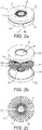
- FIG. 2a to 2c An outlet diffuser 20 in accordance with the invention is shown in more detail in Figures 2a to 2c .
- the outlet diffuser 20 has a generally cylindrical radially outer surface, preferably either with a smaller diameter (see Figure 1 ) or the same diameter (see Figure 4 ) than the pig body 11 for providing a space, between the liner sleeve and the outlet diffuser 20, into which heated gas may flow.
- the diameter of the pig body 11 is of course related to that of the pipe in which it is to be used. However, the outer diameter of the pig body 11 may be 50mm to 60mm less than inner diameter of the cylindrical part of the shroud 70.
- the diameter of the forming tool 72 is preferably 20mm to 30mm less than the inner diameter of the pipe in which it is to be used.
- the outlet diffuser 20 preferably comprises a first member 51 and a second member 52.
- the first member 51 has a generally cylindrical main section 55 with a first radius and a protruding section 54 that extends centrally from the main section 55 along the longitudinal axis 7.
- the protruding section 54 has a second radius, which is smaller than the first radius.
- the protruding section 54 is defined by a surface that curves gently away from the cylindrical main section 55.
- the second member 52 is generally annular and comprises an opening 57.
- the side of the second member 52 facing the first member 51 has a generally matching contour extending from the radially outer edge to the rim of the opening 57.
- the protruding section 54 extends into the opening 57 so as to define an annular space therebetween.
- the second member 52 is also axially spaced from the main section 55 of the first member 51. In this way, the first and second members 51 and 52 define an annular space therebetween from an opening to the heating chamber 17 in the longitudinal direction facing forwardly with respect to the pig 10 to an opening to the exterior of the pig 10 in the radially outward direction with respect to the longitudinal axis 7.
- the outlet diffuser 20 comprises a plurality of channels 60.
- Each channel 60 comprising an inlet 61 facing the front portion 11b of the pig 10 in the longitudinal direction and an outlet 62 facing radially outwardly from the pig 10 perpendicular to the longitudinal axis 7.
- Each channel 60 preferably includes a curved portion 64 joining two straight portions 63 and 65.
- the two straight portions 63 and 65 of each channel 60 include a straight inlet portion 65 and a straight outlet portion 63.
- the inlet portion 65 is shorter than the outlet portion 63.
- gas flowing through each channel 60 of the outlet diffuser 20 will enter through the inlet 61, then pass through the straight inlet portion 65 to the curved portion 64 from which it will flow to the straight outlet portion 63 and then on through the outlet 62.
- the vanes 53 extend, in a plane perpendicular to the longitudinal axis 7, along radii extending outwardly from the longitudinal axis 7.
- the distance between the vanes at the outlets 62 is greater than at the inlets 61 (because these are radially inwardly thereof).
- the radial dimension of the inlet is greater than the axial dimension of the outlet.
- the cross-sectional area of each channel is either constant, or monotonically increases, along its length.
- the inlets 61 are equally spaced radially around the longitudinal axis.
- the outlets 62 are equally spaced radially around the radially outer circumference of the outlet diffuser 20.
- a pig with or without the tree diffuser 15 or outlet diffuser 20 described above, or indeed in combination with any of the embodiments described above, preferably has baffles separating a plurality of heating coils 1 to 6 within a heating chamber 17 having a central core 56 on which the baffles 19 to 23 are mounted and which extends through apertures in the baffles 19 to 23 and through the central apertures of the coiled heating elements 1 to 6, wherein the baffles are formed as shown in Figures 3a to 3j .
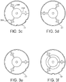
- the baffles 19 to 23 are showing respectively in Figures 3a to 3j , all viewed face on from the inlet side of the heating chamber 17.
- Each baffle has a central circular land and three arms extending radially out from the central circular land to a circular rim.
- the baffle 19 has a central circular land 357 and three arms 358, 359 and 360 which connect the central land 357 to a circular exterior rim 361.
- Each arm 358, 359 and 360 is cruciform in shape, with a cross bar extending outwardly on both sides at a position approximately two thirds along the length of the arm, beginning at the land.
- the arm 358 has a cross bar 362
- the arm 359 has a cross bar 363
- the arm 360 has a cross bar 364.
- the rim 361 is provided with notches 365, 366, 367 and 368 which are designed to engage with the stems of the heating coils 1 to 6 (and also can allow passage of sensor wiring).
- the heating coils 1 to 6 may be held in place by the stems engaging in the baffle notches 365, 366, 367 and the baffles being locked on the central shaft.
- the baffles 20, 21, 22 and 23 have features identical to the baffle 19, but the orientation of the arms of each baffle when secured in place within the cylindrical heating chamber 17 is different to the orientation of the arms of neighbouring baffles.
- the baffles 19 and 21 of Figures 3a and 3c have arms 358 and 358' approximately at the 11 o'clock position, while the arm 358" of the baffle 20 in Figure 3b is approximately at the 1 o'clock position.
- the arms 359 and 359' of the baffles 19 and 21 are at the 3 o'clock position, whilst the arm 359" of the baffle 20 is at the 9 o'clock position.
- the baffle arms 364 and 364' of the baffles 19 and 21 are at the 7 o'clock position, whilst the arm 364" of the baffle 20 is at the 5 o'clock position.
- baffles The configuration of the baffles and their orientation with respect to each other are selected so that the flow of gas along the cylindrical chamber 17 is directed by the baffles across the coils of the coiled heating elements 1 to 6.
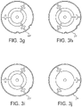
- baffles 19 to 23 are all shown with a central land of a first diameter 357 of 53mm
- alternative baffles 19', 20', 21', 22' and 23' are shown in Figures 3f to 3j , with the baffles 19', 20', 21', 22' having a larger central land of a second diameter of 57mm and the baffle 23' having a much larger central land of a third diameter of 75mm.
- This arrangement of baffles 19', 20', 21', 22' and 23' could be used in place of the baffles 19 to 23 in certain situations in order to achieve a different arrangement of gas flow through the cylindrical heating chamber 17.
- the baffle 23' with the much larger central land could also be used with the baffles 19 to 22, in place of the baffle 23.
Landscapes
- Engineering & Computer Science (AREA)
- Mechanical Engineering (AREA)
- General Engineering & Computer Science (AREA)
- Chemical & Material Sciences (AREA)
- Combustion & Propulsion (AREA)
- Textile Engineering (AREA)
- Pipe Accessories (AREA)
- Lining Or Joining Of Plastics Or The Like (AREA)
Description
- The present invention relates to a pig for use in a system for lining ducts such as water or sewage pipes or electrical ducts or gas pipes. The pig is insertable at least partly within a fabric liner sleeve located in a duct such as a water or sewage pipe and is capable of heating the liner sleeve in situ in the duct to melt or soften thermoplastic material of the liner sleeve to subsequently form, on cooling of the melted thermoplastic material, a rigid liner in the duct.
-
WO98/26919 -
WO02/25156 -
WO2004/090411 describes a further variant of pig used in a system for lining ducts. The pig described in the document is designed to force hot gas under pressure through a fabric sleeve comprising thermoplastic material and reinforcing fibres, and the pig has heating means both within and outside the fabric sleeve, to ensure uniform heating of the sleeve. -
DE-A-3904524 discloses a process for lining pipelines. Damaged pipelines which are not accessible from the outside are lined by means of a plastic hose whose diameter is smaller than the internal width of the pipe which is to be repaired. The hose consists of a noncrosslinked plastic based on polyolefins or polyolefin copolymers or aromatic polyesters. This hose is radially expanded in a mechanical manner by means of an expanding device at a temperature lying beneath the softening point of the plastic, with the result that the hose lies against the pipe wall in a dimensionally stable manner and forms a selfsupporting pipe coating. -
GB-A-2554431 - In order to achieve a practical and useful system of the type described in the prior art, the length of the pig is usually limited to around 700mm depending on the application or else navigating the pig around a curve in the pipe can become too difficult. This means that there is a limited space available within the pig for heating air to a temperature sufficient to ensure adequate heating of the fabric sleeve and also to ensure uniform melting of the thermoplastic material in the fabric sleeve. It is important not only to ensure that a correct air temperature is reached which will facilitate the melting of the thermoplastic material, but also to ensure that the hot air delivered from the pig is of a uniform temperature, otherwise there will be cold and hot spots in the fabric sleeve, which will mean that the duct liner is incorrectly formed or formed with points of weakness.
- Furthermore, the inventors have realised that the means by which the hot air delivered must be carefully designed in order to provide a uniform delivery of hot air to the fabric sleeve around the circumference of the pig, otherwise, even with a uniformly heated air supply there will be cold and hot spots in the fabric sleeve, leading to points of weakness.
- According to the invention, there is provided a pig defined by the claims.
- For a better understanding of the invention, and to show how the same may be put into effect, reference will now be made, by way of example only, to the accompanying drawings in which:
-
Figure 1 shows an embodiment of a pig with an outlet diffuser in accordance with the invention; -
Figure 2a shows the outlet diffuser of the pig shown inFigure 1 ; -
Figure 2b shows the outlet diffuser ofFigure 2a in an exploded view; -
Figure 2c shows a schematic layout of the outlet diffuser ofFigure 2a ; -
Figures 3a to 3j show baffles for use in a pig; and -
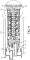
Figure 4 shows an alternative embodiment of a pig in accordance with the invention. -
Figure 1 shows apig 10 for fitting a liner to the inside of a pipe. Thepig 10 is for use in a method of lining a water or sewage pipe as described in any ofWO98/26919 WO2004/090411 orWO2004/090411 . In particular, thepig 10 is designed to heat a liner sleeve of thermoplastic material and any reinforcing elements. Thepig 10 can be used to heat a liner sleeve to form a rigid liner in any duct, for instance an electrical duct or a gas pipe as well as a water or sewage pipe. - The
pig 10 has apig body 11 defining a longitudinal axis 7 that extends in a longitudinal direction from arear portion 11a to afront portion 11b. Thepig body 11 is generally elongate in the longitudinal direction. - The
pig 10 comprises anoutlet diffuser 20 forming part of therear portion 11a and a heating chamber 17 (which is preferably cylindrical) within which is housed aheater 16. - The
pig 10 preferably comprises a formingtool 72 at the rear end of therear portion 11a for forcing the heated liner sleeve radially outwardly into the surface of a pipe or duct. The formingtool 72 has a generally cylindrical radially outer surface with a larger diameter than thepig body 11. - Preferably, a
shroud 70 around the pigmain body 11. The shroud is tubular and generally cylindrical. As shown inFigure 4 , in some embodiments, theshroud 70 may comprise longitudinally extendingmembers 178 spaced around its outer circumference. The longitudinally extendingmembers 178 are resilient and so are arranged to centre theshroud - In this way, the longitudinally extending
members 178 can axially align the pigmain body 11 within the pipe. - Moreover, the longitudinally extending
members 178 are spaced apart and so form a flow path between theshroud 70 and the pipe through which fluid (for example, exhaust heating gas) can escape through the pipe ahead of thepig 10. - The
front portion 11b of the pig is preferably formed with atapered nose 11e. Thetapered nose 11e has anouter diameter 11d. The shroud preferably has either a plurality ofspacers annular spacer 175. The inner diameter of the spacer(s) 75, 175 is/are less than theouter diameter 11d of thenose 11e. - As can be seen from
Figure 4 , the spacer(s) 175 preferably have a tapered surface that is shaped so as to be substantially complementary to the outer surface of thenose 11e. - In use, the liner sleeve may pass between the
shroud 70 and the pigmain body 11. The liner has a thickness X. As the pigmain body 11 passes through the liner, the liner pushes theshroud 70 forward and theshroud 70 centres thepig body 11 via force transmitted through the liner. - The contact between the
nose 11e, the liner, and theshroud 70 can create a seal that prevents heated gas ejected from thediffuser 20 from passing forward within the sleeve ahead of the pigmain body 11. - The
shroud rear end diffuser 20. Preferably, the shroudrear end diffuser 20. - Optionally, there may be provided a cable duct for housing power cables to power the
heater 16 and/or thermocouple signal lines. - The
heater 16 is preferably formed from a plurality of annular coiled heating elements 1 to 6 all arranged around the common longitudinal axis 7. Thepig 10 has a gas supply port 8 for supplying gas to theheating chamber 17, and heated gas leaves thepig 10 in a radial direction via a series of apertures 9 in anoutlet diffuser 20 at therear end 11a of thepig 10. Thus, theheating chamber 17 forms a flow channel in thepig body 11 from a gas supply port 8 to theoutlet diffuser 20. - Optionally, the gas supply port 8 is radially offset from the axis 7.
- Gas delivered by the gas supply port 8 may be directed through a
tree diffuser 15 to deliver gas to theheating chamber 17. Thetree diffuser 15 comprises branch pipes extending radially out from a central trunk portion that is in communication with inlet tube 8. Preferably, at least a portion of the branch pipes extend in a plane perpendicular to the longitudinal axis 7. - Gas flow through the
heating chamber 17 and thereby the heating efficiency of thepig 10 may be assisted by the use ofbaffles 19 to 23 and acentral core 56 on which thebaffles 19 to 23 are mounted and which extends through apertures in thebaffles 19 to 23 and through the central apertures of the coiled heating elements 2 to 6. Thecentral core 56 ensures that the gas flow through theheating chamber 17 passes across the coiled heating elements 2 to 6, rather than passing through their aligned central apertures. - Preferable forms of the
baffles 19 to 23 are shown, respectively, inFigures 3a to 3j , as described below. - An
outlet diffuser 20 in accordance with the invention is shown in more detail inFigures 2a to 2c . - The
outlet diffuser 20 has a generally cylindrical radially outer surface, preferably either with a smaller diameter (seeFigure 1 ) or the same diameter (seeFigure 4 ) than thepig body 11 for providing a space, between the liner sleeve and theoutlet diffuser 20, into which heated gas may flow. - The diameter of the
pig body 11 is of course related to that of the pipe in which it is to be used. However, the outer diameter of thepig body 11 may be 50mm to 60mm less than inner diameter of the cylindrical part of theshroud 70. - The diameter of the forming
tool 72 is preferably 20mm to 30mm less than the inner diameter of the pipe in which it is to be used.. - The
outlet diffuser 20 preferably comprises afirst member 51 and asecond member 52. - The
first member 51 has a generally cylindricalmain section 55 with a first radius and a protrudingsection 54 that extends centrally from themain section 55 along the longitudinal axis 7. - The protruding
section 54 has a second radius, which is smaller than the first radius. Preferably, the protrudingsection 54 is defined by a surface that curves gently away from the cylindricalmain section 55. - The
second member 52 is generally annular and comprises anopening 57. Preferably, the side of thesecond member 52 facing thefirst member 51 has a generally matching contour extending from the radially outer edge to the rim of theopening 57. - The protruding
section 54 extends into theopening 57 so as to define an annular space therebetween. Thesecond member 52 is also axially spaced from themain section 55 of thefirst member 51. In this way, the first andsecond members heating chamber 17 in the longitudinal direction facing forwardly with respect to thepig 10 to an opening to the exterior of thepig 10 in the radially outward direction with respect to the longitudinal axis 7. - So as to improve the distribution of heated gas directed out of the
pig 10 through theoutlet diffuser 20, and also advantageously to suppress rotational flow of heated gas around the longitudinal axis of thepig 10, it has been found preferable to divide the annular space into discrete channels. Accordingly, within the annular space there is provided a plurality ofvanes 53. - Thus, the
outlet diffuser 20 comprises a plurality ofchannels 60. Eachchannel 60 comprising aninlet 61 facing thefront portion 11b of thepig 10 in the longitudinal direction and anoutlet 62 facing radially outwardly from thepig 10 perpendicular to the longitudinal axis 7. - Each
channel 60 preferably includes acurved portion 64 joining twostraight portions straight portions channel 60 include astraight inlet portion 65 and astraight outlet portion 63. Preferably, theinlet portion 65 is shorter than theoutlet portion 63. - As can be most easily seen with reference to the shape of the
vanes 53 in the exploded view ofFigure 2b , gas flowing through eachchannel 60 of theoutlet diffuser 20 will enter through theinlet 61, then pass through thestraight inlet portion 65 to thecurved portion 64 from which it will flow to thestraight outlet portion 63 and then on through theoutlet 62. - As can be most easily seen from the schematic layout of
Figure 2c , thevanes 53 extend, in a plane perpendicular to the longitudinal axis 7, along radii extending outwardly from the longitudinal axis 7. Thus, the distance between the vanes at theoutlets 62 is greater than at the inlets 61 (because these are radially inwardly thereof). As such, the radial dimension of the inlet is greater than the axial dimension of the outlet. Preferably, the cross-sectional area of each channel is either constant, or monotonically increases, along its length. Preferably, theinlets 61 are equally spaced radially around the longitudinal axis. Preferably, theoutlets 62 are equally spaced radially around the radially outer circumference of theoutlet diffuser 20. - It is preferred for a smooth flow path from the
heating chamber 17 to thediffuser 20 that the radially innermost edge of theinlets 61 is aligned with the outer edge of thecentral core 56. - The inventors have also learned that a pig with or without the
tree diffuser 15 oroutlet diffuser 20 described above, or indeed in combination with any of the embodiments described above, preferably has baffles separating a plurality of heating coils 1 to 6 within aheating chamber 17 having acentral core 56 on which thebaffles 19 to 23 are mounted and which extends through apertures in thebaffles 19 to 23 and through the central apertures of the coiled heating elements 1 to 6, wherein the baffles are formed as shown inFigures 3a to 3j . - The
baffles 19 to 23 are showing respectively inFigures 3a to 3j , all viewed face on from the inlet side of theheating chamber 17. Each baffle has a central circular land and three arms extending radially out from the central circular land to a circular rim. For instance, thebaffle 19 has a centralcircular land 357 and threearms central land 357 to a circularexterior rim 361. Eacharm Figure 3a thearm 358 has across bar 362, thearm 359 has across bar 363 and thearm 360 has across bar 364. - Also in
Figure 3 it can also be seen that therim 361 is provided withnotches baffle notches - The
baffles baffle 19, but the orientation of the arms of each baffle when secured in place within thecylindrical heating chamber 17 is different to the orientation of the arms of neighbouring baffles. For instance, looking atFigures 3a, 3b , and3c it can be seen that thebaffles Figures 3a and3c havearms 358 and 358' approximately at the 11 o'clock position, while thearm 358" of thebaffle 20 inFigure 3b is approximately at the 1 o'clock position. In a similar way thearms 359 and 359' of thebaffles arm 359" of thebaffle 20 is at the 9 o'clock position. Furthermore thebaffle arms 364 and 364' of thebaffles arm 364" of thebaffle 20 is at the 5 o'clock position. - The configuration of the baffles and their orientation with respect to each other are selected so that the flow of gas along the
cylindrical chamber 17 is directed by the baffles across the coils of the coiled heating elements 1 to 6. - Whereas in
Figures 3a to 3e thebaffles 19 to 23 are all shown with a central land of afirst diameter 357 of 53mm, alternative baffles 19', 20', 21', 22' and 23' are shown inFigures 3f to 3j , with the baffles 19', 20', 21', 22' having a larger central land of a second diameter of 57mm and the baffle 23' having a much larger central land of a third diameter of 75mm. This arrangement of baffles 19', 20', 21', 22' and 23' could be used in place of thebaffles 19 to 23 in certain situations in order to achieve a different arrangement of gas flow through thecylindrical heating chamber 17. The baffle 23' with the much larger central land could also be used with thebaffles 19 to 22, in place of thebaffle 23.
Claims (15)
- A pig (10) for fitting a liner to the inside of a pipe, comprising:a pig body (11) defining a longitudinal axis (7) in a longitudinal direction from a front portion (11b) to a rear portion (11a);a gas supply port (8) in the front portion (11b);a gas outlet diffuser (20) forming part of the rear portion (11a);a heating chamber (17) in the pig body (11) forming a flow path from a fluid inlet to the outlet diffuser (20); anda heater (16) within the heating chamber (17),wherein the outlet diffuser (20) comprises a plurality of channels (60), each channel (60) comprising an inlet (61) facing the front portion (11b) in the longitudinal direction and an outlet (62) extending radially outwardly from the longitudinal axis (7).
- The pig (10) of claim 1, wherein each channel (60) includes a curved portion (64) between the inlet (61) and outlet (62).
- The pig (10) of claim 2, wherein each channel (60) includes a straight outlet portion (63) between the curved portion (64) and the outlet (62).
- The pig (10) of claim 3, wherein:each channel (60) includes a straight inlet portion (65) between the curved portion (64) and the inlet (61); andthe inlet portion (65) is shorter than the outlet portion (63).
- The pig (10) of any preceding claim, wherein the cross-sectional area of each channel (60) is constant or monotonically increases along its length.
- The pig (10) of any preceding claim, wherein the inlets (61) of the channels (60) are spaced radially from and circumferentially around the longitudinal axis (7).
- The pig (10) of claim 6, further comprising a central core (56) extending along the longitudinal axis (7) to the outlet diffuser (20), wherein the radially innermost edge of the inlets (61) of the channels (60) is aligned with the outer edge of the core (56).
- The pig (10) of any preceding claim, wherein the outlets (62) are spaced around the outer circumference of the outlet diffuser (20).
- The pig (10) of any preceding claim, wherein:the pig body (11) has a greater diameter than the outlet diffuser (20); and/orthe outlet diffuser (20) has a generally cylindrical radially outer surface.
- The pig (10) of any preceding claim, wherein the channels (60) are defined by a plurality of vanes (53) extending between a first member (51) of the outlet diffuser (20) and a second member (52) of the outlet diffuser (20).
- The pig (10) of claim 10, wherein:the first member (51) has a generally cylindrical main section (55) with a first radius and a protruding section (54) that extends centrally from the main section (55) along the longitudinal axis (7), the protruding section (54) having a second radius, the second radius being smaller than the first radius; andthe second member (52) is generally annular and surrounds the protruding section (54) so as to define a space therebetween in which the vanes (53) are located.
- The pig (10) of any preceding claim, further comprising a shroud (70), surrounding the pig body (11).
- The pig (10) of claim 12, wherein the shroud (70) comprises a plurality of members (178) on its outer surface for contacting the inner surface of a pipe.
- The pig of claim 13, wherein the members (178) are elongate and extend longitudinally for defining a flow path therebetween.
- The pig (10) of any one of claims 12 to 14, wherein the pig main body (11) has a tapered nose portion (11e) and the shroud (70) has one or more spacers (75,175) on its inner surface, the spacer(s) (75,175) having a complementary shape to the tapered surface of the nose (11e).
Applications Claiming Priority (2)
| Application Number | Priority Date | Filing Date | Title |
|---|---|---|---|
| GB1802664.1A GB2571127B (en) | 2018-02-19 | 2018-02-19 | A pig for use in a system for lining ducts water or sewage pipes |
| PCT/GB2019/050441 WO2019158950A1 (en) | 2018-02-19 | 2019-02-19 | A pig for use in a system for lining ducts water or sewage pipes |
Publications (2)
| Publication Number | Publication Date |
|---|---|
| EP3755934A1 EP3755934A1 (en) | 2020-12-30 |
| EP3755934B1 true EP3755934B1 (en) | 2022-12-14 |
Family
ID=61783632
Family Applications (1)
| Application Number | Title | Priority Date | Filing Date |
|---|---|---|---|
| EP19708609.3A Active EP3755934B1 (en) | 2018-02-19 | 2019-02-19 | A pig for use in a system for lining ducts water or sewage pipes |
Country Status (8)
| Country | Link |
|---|---|
| US (2) | US11305492B2 (en) |
| EP (1) | EP3755934B1 (en) |
| JP (1) | JP7208249B2 (en) |
| AU (1) | AU2019221821A1 (en) |
| CA (1) | CA3090103A1 (en) |
| ES (1) | ES2933957T3 (en) |
| GB (1) | GB2571127B (en) |
| WO (1) | WO2019158950A1 (en) |
Families Citing this family (2)
| Publication number | Priority date | Publication date | Assignee | Title |
|---|---|---|---|---|
| GB2554431B (en) | 2016-09-27 | 2018-08-22 | Aqualiner Ltd | A pig for use in a system for lining ducts |
| SE544036C2 (en) * | 2019-05-08 | 2021-11-16 | Peanta Invent Ab | Light head, with led-plate and spacer, for use in relining pipes and a light head system |
Family Cites Families (21)
| Publication number | Priority date | Publication date | Assignee | Title |
|---|---|---|---|---|
| US3643280A (en) | 1969-12-19 | 1972-02-22 | Marvin D Powers | Pipeline pigs |
| US3765349A (en) | 1971-05-06 | 1973-10-16 | Gerber Garment Technology Inc | Apparatus for forming bundles of sheet material |
| WO1987001173A1 (en) | 1985-08-15 | 1987-02-26 | Tate Pipe Lining Processes Limited | A method of and apparatus for lining pipes |
| GB8608805D0 (en) | 1986-04-11 | 1986-05-14 | Du Pont Uk | Thermoplastic polymer-lined pipe |
| JPS63162221A (en) * | 1986-12-26 | 1988-07-05 | Osaka Gas Co Ltd | Process of lining for pipe |
| JPH01154729A (en) | 1987-12-11 | 1989-06-16 | Osaka Bosui Constr Co Ltd | Engineering method for lining rigid tube onto inner surface of tube |
| DE3904524C3 (en) * | 1989-02-15 | 1994-05-11 | Guenter Dr Ing Klemm | Expansion device for lining pipelines |
| DE4119161A1 (en) | 1991-06-11 | 1992-12-17 | Werner & Pfleiderer | METHOD AND DEVICE FOR LINING THE INNER WALL OF A CHANNEL PIPE |
| GB9425503D0 (en) | 1994-12-17 | 1995-02-15 | Wood John | Method and apparatus for re-sizing thermoplastic pipes |
| GB9626060D0 (en) | 1996-12-16 | 1997-02-05 | United Utilities Plc | Thermoplastic composite products |
| JPH11147063A (en) * | 1997-11-17 | 1999-06-02 | Osaka Gas Co Ltd | Method and apparatus for lining inside of pipe |
| JP2001310388A (en) | 2000-04-27 | 2001-11-06 | Osaka Gas Co Ltd | Method for finishing inside of thermoplastic resin cylinder and pig for expansion |
| GB0022921D0 (en) | 2000-09-19 | 2000-11-01 | Sev Trent Water Ltd | Lining ducts |
| JP2002086564A (en) | 2000-09-20 | 2002-03-26 | Shonan Gosei Jushi Seisakusho:Kk | Pipe lining method |
| GB0308529D0 (en) | 2003-04-12 | 2003-05-21 | Sev Trent Water Ltd | Lining ducts |
| DE202006000969U1 (en) | 2006-01-20 | 2007-05-24 | Rosen Swiss Ag | cleaning pig |
| US7827646B2 (en) | 2008-02-08 | 2010-11-09 | Tdw Delaware, Inc. | Vortex inhibitor dispersal pig |
| JP2016016615A (en) | 2014-07-10 | 2016-02-01 | 積水化学工業株式会社 | Liner material, production method and execution method thereof, and heating/cooling tool to be used in the execution method |
| SE540893C2 (en) * | 2016-04-19 | 2018-12-11 | Peanta Invent Ab | Light head for use in relining pipes |
| GB2554431B (en) * | 2016-09-27 | 2018-08-22 | Aqualiner Ltd | A pig for use in a system for lining ducts |
| DK3336404T3 (en) * | 2016-12-14 | 2020-01-13 | Bolonia Servicios E Ingenieros S L | DEVICE TO CURE INTERNAL ART RESIN PIPE LINES |
-
2018
- 2018-02-19 GB GB1802664.1A patent/GB2571127B/en active Active
-
2019
- 2019-02-19 JP JP2020543860A patent/JP7208249B2/en active Active
- 2019-02-19 US US16/970,571 patent/US11305492B2/en active Active
- 2019-02-19 EP EP19708609.3A patent/EP3755934B1/en active Active
- 2019-02-19 AU AU2019221821A patent/AU2019221821A1/en active Pending
- 2019-02-19 CA CA3090103A patent/CA3090103A1/en active Pending
- 2019-02-19 WO PCT/GB2019/050441 patent/WO2019158950A1/en unknown
- 2019-02-19 ES ES19708609T patent/ES2933957T3/en active Active
-
2022
- 2022-03-23 US US17/702,297 patent/US11613083B2/en active Active
Also Published As
| Publication number | Publication date |
|---|---|
| ES2933957T3 (en) | 2023-02-15 |
| GB201802664D0 (en) | 2018-04-04 |
| GB2571127A (en) | 2019-08-21 |
| US20220212416A1 (en) | 2022-07-07 |
| US11613083B2 (en) | 2023-03-28 |
| JP7208249B2 (en) | 2023-01-18 |
| EP3755934A1 (en) | 2020-12-30 |
| US20210107232A1 (en) | 2021-04-15 |
| JP2021513927A (en) | 2021-06-03 |
| AU2019221821A1 (en) | 2020-08-27 |
| CA3090103A1 (en) | 2019-08-22 |
| GB2571127B (en) | 2021-03-31 |
| WO2019158950A1 (en) | 2019-08-22 |
| US11305492B2 (en) | 2022-04-19 |
Similar Documents
| Publication | Publication Date | Title |
|---|---|---|
| US11613083B2 (en) | Pig for use in a system for lining ducts water or sewage pipes | |
| JP6137925B2 (en) | Fittings, especially quick fittings | |
| JPH0639922A (en) | Method for lining duct | |
| CN1278323A (en) | Tube assembly for auxiliary heating and air conditioning system | |
| ES2673281T5 (en) | Thermal roller and production procedure | |
| EP3235625B1 (en) | Apparatus and method for making bell joints on plastic pipes | |
| JPH11936A (en) | Injection molding device | |
| JP2004217017A (en) | Piping for heater, joint and connecting structure between piping for heater and joint | |
| JP2020533543A (en) | connector | |
| EP3519723B1 (en) | A pig for use in a system for lining ducts | |
| JP5503273B2 (en) | Method for expanding the rehabilitation pipe using the tube expansion device | |
| CN112689727B (en) | Corrugated pipe assembly and sleeve thereof | |
| JP2021513927A5 (en) | ||
| EP1304392B1 (en) | Apparatus and method for quenching thin-walled metal hollow casing | |
| JP2019529197A5 (en) | ||
| CN108136336A (en) | The non-contact hot forming of fibre bundle | |
| JP2019089056A (en) | Heating hose on coating device of hot melt adhesive and fitting method of inner tube to heating hose | |
| CN109702435B (en) | Flange assembly and machining method thereof | |
| CN206690531U (en) | A kind of minor-caliber plastic pipe flange shaped device | |
| JPH07217776A (en) | Ribbed bellowslike pipe and manufacture thereof | |
| AU1637300A (en) | Duct fittings | |
| CN103302878A (en) | Method for manufacturing guide pipe | |
| CS197052B1 (en) | Electric pistol for welding the thermoplasts with the double isolation | |
| KR20070047539A (en) | Cooling-heating piping manufacturing apparatus and manufacturing method using it |
Legal Events
| Date | Code | Title | Description |
|---|---|---|---|
| STAA | Information on the status of an ep patent application or granted ep patent |
Free format text: STATUS: UNKNOWN |
|
| STAA | Information on the status of an ep patent application or granted ep patent |
Free format text: STATUS: THE INTERNATIONAL PUBLICATION HAS BEEN MADE |
|
| PUAI | Public reference made under article 153(3) epc to a published international application that has entered the european phase |
Free format text: ORIGINAL CODE: 0009012 |
|
| STAA | Information on the status of an ep patent application or granted ep patent |
Free format text: STATUS: REQUEST FOR EXAMINATION WAS MADE |
|
| 17P | Request for examination filed |
Effective date: 20200908 |
|
| AK | Designated contracting states |
Kind code of ref document: A1 Designated state(s): AL AT BE BG CH CY CZ DE DK EE ES FI FR GB GR HR HU IE IS IT LI LT LU LV MC MK MT NL NO PL PT RO RS SE SI SK SM TR |
|
| AX | Request for extension of the european patent |
Extension state: BA ME |
|
| DAV | Request for validation of the european patent (deleted) | ||
| DAX | Request for extension of the european patent (deleted) | ||
| REG | Reference to a national code |
Ref country code: DE Ref legal event code: R079 Ref document number: 602019023139 Country of ref document: DE Free format text: PREVIOUS MAIN CLASS: F16L0055400000 Ipc: F16L0055180000 |
|
| GRAP | Despatch of communication of intention to grant a patent |
Free format text: ORIGINAL CODE: EPIDOSNIGR1 |
|
| STAA | Information on the status of an ep patent application or granted ep patent |
Free format text: STATUS: GRANT OF PATENT IS INTENDED |
|
| RIC1 | Information provided on ipc code assigned before grant |
Ipc: F16L 55/165 20060101ALI20220620BHEP Ipc: F16L 55/18 20060101AFI20220620BHEP |
|
| INTG | Intention to grant announced |
Effective date: 20220707 |
|
| GRAS | Grant fee paid |
Free format text: ORIGINAL CODE: EPIDOSNIGR3 |
|
| GRAA | (expected) grant |
Free format text: ORIGINAL CODE: 0009210 |
|
| STAA | Information on the status of an ep patent application or granted ep patent |
Free format text: STATUS: THE PATENT HAS BEEN GRANTED |
|
| AK | Designated contracting states |
Kind code of ref document: B1 Designated state(s): AL AT BE BG CH CY CZ DE DK EE ES FI FR GB GR HR HU IE IS IT LI LT LU LV MC MK MT NL NO PL PT RO RS SE SI SK SM TR |
|
| REG | Reference to a national code |
Ref country code: GB Ref legal event code: FG4D |
|
| REG | Reference to a national code |
Ref country code: CH Ref legal event code: EP |
|
| REG | Reference to a national code |
Ref country code: DE Ref legal event code: R096 Ref document number: 602019023139 Country of ref document: DE |
|
| REG | Reference to a national code |
Ref country code: IE Ref legal event code: FG4D |
|
| REG | Reference to a national code |
Ref country code: AT Ref legal event code: REF Ref document number: 1537867 Country of ref document: AT Kind code of ref document: T Effective date: 20230115 |
|
| REG | Reference to a national code |
Ref country code: NL Ref legal event code: FP |
|
| REG | Reference to a national code |
Ref country code: ES Ref legal event code: FG2A Ref document number: 2933957 Country of ref document: ES Kind code of ref document: T3 Effective date: 20230215 |
|
| REG | Reference to a national code |
Ref country code: LT Ref legal event code: MG9D |
|
| PG25 | Lapsed in a contracting state [announced via postgrant information from national office to epo] |
Ref country code: SE Free format text: LAPSE BECAUSE OF FAILURE TO SUBMIT A TRANSLATION OF THE DESCRIPTION OR TO PAY THE FEE WITHIN THE PRESCRIBED TIME-LIMIT Effective date: 20221214 Ref country code: NO Free format text: LAPSE BECAUSE OF FAILURE TO SUBMIT A TRANSLATION OF THE DESCRIPTION OR TO PAY THE FEE WITHIN THE PRESCRIBED TIME-LIMIT Effective date: 20230314 Ref country code: LT Free format text: LAPSE BECAUSE OF FAILURE TO SUBMIT A TRANSLATION OF THE DESCRIPTION OR TO PAY THE FEE WITHIN THE PRESCRIBED TIME-LIMIT Effective date: 20221214 Ref country code: FI Free format text: LAPSE BECAUSE OF FAILURE TO SUBMIT A TRANSLATION OF THE DESCRIPTION OR TO PAY THE FEE WITHIN THE PRESCRIBED TIME-LIMIT Effective date: 20221214 |
|
| PGFP | Annual fee paid to national office [announced via postgrant information from national office to epo] |
Ref country code: FR Payment date: 20230214 Year of fee payment: 5 |
|
| REG | Reference to a national code |
Ref country code: AT Ref legal event code: MK05 Ref document number: 1537867 Country of ref document: AT Kind code of ref document: T Effective date: 20221214 |
|
| PG25 | Lapsed in a contracting state [announced via postgrant information from national office to epo] |
Ref country code: RS Free format text: LAPSE BECAUSE OF FAILURE TO SUBMIT A TRANSLATION OF THE DESCRIPTION OR TO PAY THE FEE WITHIN THE PRESCRIBED TIME-LIMIT Effective date: 20221214 Ref country code: LV Free format text: LAPSE BECAUSE OF FAILURE TO SUBMIT A TRANSLATION OF THE DESCRIPTION OR TO PAY THE FEE WITHIN THE PRESCRIBED TIME-LIMIT Effective date: 20221214 Ref country code: HR Free format text: LAPSE BECAUSE OF FAILURE TO SUBMIT A TRANSLATION OF THE DESCRIPTION OR TO PAY THE FEE WITHIN THE PRESCRIBED TIME-LIMIT Effective date: 20221214 Ref country code: GR Free format text: LAPSE BECAUSE OF FAILURE TO SUBMIT A TRANSLATION OF THE DESCRIPTION OR TO PAY THE FEE WITHIN THE PRESCRIBED TIME-LIMIT Effective date: 20230315 |
|
| PGFP | Annual fee paid to national office [announced via postgrant information from national office to epo] |
Ref country code: BE Payment date: 20230215 Year of fee payment: 5 |
|
| P01 | Opt-out of the competence of the unified patent court (upc) registered |
Effective date: 20230414 |
|
| PG25 | Lapsed in a contracting state [announced via postgrant information from national office to epo] |
Ref country code: SM Free format text: LAPSE BECAUSE OF FAILURE TO SUBMIT A TRANSLATION OF THE DESCRIPTION OR TO PAY THE FEE WITHIN THE PRESCRIBED TIME-LIMIT Effective date: 20221214 Ref country code: RO Free format text: LAPSE BECAUSE OF FAILURE TO SUBMIT A TRANSLATION OF THE DESCRIPTION OR TO PAY THE FEE WITHIN THE PRESCRIBED TIME-LIMIT Effective date: 20221214 Ref country code: PT Free format text: LAPSE BECAUSE OF FAILURE TO SUBMIT A TRANSLATION OF THE DESCRIPTION OR TO PAY THE FEE WITHIN THE PRESCRIBED TIME-LIMIT Effective date: 20230414 Ref country code: EE Free format text: LAPSE BECAUSE OF FAILURE TO SUBMIT A TRANSLATION OF THE DESCRIPTION OR TO PAY THE FEE WITHIN THE PRESCRIBED TIME-LIMIT Effective date: 20221214 Ref country code: CZ Free format text: LAPSE BECAUSE OF FAILURE TO SUBMIT A TRANSLATION OF THE DESCRIPTION OR TO PAY THE FEE WITHIN THE PRESCRIBED TIME-LIMIT Effective date: 20221214 Ref country code: AT Free format text: LAPSE BECAUSE OF FAILURE TO SUBMIT A TRANSLATION OF THE DESCRIPTION OR TO PAY THE FEE WITHIN THE PRESCRIBED TIME-LIMIT Effective date: 20221214 |
|
| PGFP | Annual fee paid to national office [announced via postgrant information from national office to epo] |
Ref country code: IT Payment date: 20230328 Year of fee payment: 5 |
|
| PG25 | Lapsed in a contracting state [announced via postgrant information from national office to epo] |
Ref country code: SK Free format text: LAPSE BECAUSE OF FAILURE TO SUBMIT A TRANSLATION OF THE DESCRIPTION OR TO PAY THE FEE WITHIN THE PRESCRIBED TIME-LIMIT Effective date: 20221214 Ref country code: PL Free format text: LAPSE BECAUSE OF FAILURE TO SUBMIT A TRANSLATION OF THE DESCRIPTION OR TO PAY THE FEE WITHIN THE PRESCRIBED TIME-LIMIT Effective date: 20221214 Ref country code: IS Free format text: LAPSE BECAUSE OF FAILURE TO SUBMIT A TRANSLATION OF THE DESCRIPTION OR TO PAY THE FEE WITHIN THE PRESCRIBED TIME-LIMIT Effective date: 20230414 Ref country code: AL Free format text: LAPSE BECAUSE OF FAILURE TO SUBMIT A TRANSLATION OF THE DESCRIPTION OR TO PAY THE FEE WITHIN THE PRESCRIBED TIME-LIMIT Effective date: 20221214 |
|
| REG | Reference to a national code |
Ref country code: DE Ref legal event code: R097 Ref document number: 602019023139 Country of ref document: DE |
|
| PG25 | Lapsed in a contracting state [announced via postgrant information from national office to epo] |
Ref country code: MC Free format text: LAPSE BECAUSE OF FAILURE TO SUBMIT A TRANSLATION OF THE DESCRIPTION OR TO PAY THE FEE WITHIN THE PRESCRIBED TIME-LIMIT Effective date: 20221214 |
|
| PLBE | No opposition filed within time limit |
Free format text: ORIGINAL CODE: 0009261 |
|
| STAA | Information on the status of an ep patent application or granted ep patent |
Free format text: STATUS: NO OPPOSITION FILED WITHIN TIME LIMIT |
|
| PG25 | Lapsed in a contracting state [announced via postgrant information from national office to epo] |
Ref country code: LU Free format text: LAPSE BECAUSE OF NON-PAYMENT OF DUE FEES Effective date: 20230219 Ref country code: DK Free format text: LAPSE BECAUSE OF FAILURE TO SUBMIT A TRANSLATION OF THE DESCRIPTION OR TO PAY THE FEE WITHIN THE PRESCRIBED TIME-LIMIT Effective date: 20221214 |
|
| 26N | No opposition filed |
Effective date: 20230915 |
|
| PG25 | Lapsed in a contracting state [announced via postgrant information from national office to epo] |
Ref country code: SI Free format text: LAPSE BECAUSE OF FAILURE TO SUBMIT A TRANSLATION OF THE DESCRIPTION OR TO PAY THE FEE WITHIN THE PRESCRIBED TIME-LIMIT Effective date: 20221214 |
|
| PGFP | Annual fee paid to national office [announced via postgrant information from national office to epo] |
Ref country code: IE Payment date: 20240216 Year of fee payment: 6 Ref country code: ES Payment date: 20240319 Year of fee payment: 6 Ref country code: NL Payment date: 20240216 Year of fee payment: 6 |
|
| PGFP | Annual fee paid to national office [announced via postgrant information from national office to epo] |
Ref country code: DE Payment date: 20240219 Year of fee payment: 6 Ref country code: CH Payment date: 20240301 Year of fee payment: 6 Ref country code: GB Payment date: 20240216 Year of fee payment: 6 |