EP3755916B1 - Elektrisch angetriebener kupplungsaktuator - Google Patents
Elektrisch angetriebener kupplungsaktuator Download PDFInfo
- Publication number
- EP3755916B1 EP3755916B1 EP18745825.2A EP18745825A EP3755916B1 EP 3755916 B1 EP3755916 B1 EP 3755916B1 EP 18745825 A EP18745825 A EP 18745825A EP 3755916 B1 EP3755916 B1 EP 3755916B1
- Authority
- EP
- European Patent Office
- Prior art keywords
- clutch
- spindle nut
- driving force
- spindle
- value
- Prior art date
- Legal status (The legal status is an assumption and is not a legal conclusion. Google has not performed a legal analysis and makes no representation as to the accuracy of the status listed.)
- Active
Links
Images


Classifications
-
- F—MECHANICAL ENGINEERING; LIGHTING; HEATING; WEAPONS; BLASTING
- F16—ENGINEERING ELEMENTS AND UNITS; GENERAL MEASURES FOR PRODUCING AND MAINTAINING EFFECTIVE FUNCTIONING OF MACHINES OR INSTALLATIONS; THERMAL INSULATION IN GENERAL
- F16D—COUPLINGS FOR TRANSMITTING ROTATION; CLUTCHES; BRAKES
- F16D28/00—Electrically-actuated clutches
-
- F—MECHANICAL ENGINEERING; LIGHTING; HEATING; WEAPONS; BLASTING
- F16—ENGINEERING ELEMENTS AND UNITS; GENERAL MEASURES FOR PRODUCING AND MAINTAINING EFFECTIVE FUNCTIONING OF MACHINES OR INSTALLATIONS; THERMAL INSULATION IN GENERAL
- F16D—COUPLINGS FOR TRANSMITTING ROTATION; CLUTCHES; BRAKES
- F16D23/00—Details of mechanically-actuated clutches not specific for one distinct type
- F16D23/12—Mechanical clutch-actuating mechanisms arranged outside the clutch as such
-
- F—MECHANICAL ENGINEERING; LIGHTING; HEATING; WEAPONS; BLASTING
- F16—ENGINEERING ELEMENTS AND UNITS; GENERAL MEASURES FOR PRODUCING AND MAINTAINING EFFECTIVE FUNCTIONING OF MACHINES OR INSTALLATIONS; THERMAL INSULATION IN GENERAL
- F16D—COUPLINGS FOR TRANSMITTING ROTATION; CLUTCHES; BRAKES
- F16D48/00—External control of clutches
- F16D48/06—Control by electric or electronic means, e.g. of fluid pressure
- F16D48/064—Control of electrically or electromagnetically actuated clutches
-
- F—MECHANICAL ENGINEERING; LIGHTING; HEATING; WEAPONS; BLASTING
- F16—ENGINEERING ELEMENTS AND UNITS; GENERAL MEASURES FOR PRODUCING AND MAINTAINING EFFECTIVE FUNCTIONING OF MACHINES OR INSTALLATIONS; THERMAL INSULATION IN GENERAL
- F16D—COUPLINGS FOR TRANSMITTING ROTATION; CLUTCHES; BRAKES
- F16D7/00—Slip couplings, e.g. slipping on overload, for absorbing shock
- F16D7/04—Slip couplings, e.g. slipping on overload, for absorbing shock of the ratchet type
- F16D7/048—Slip couplings, e.g. slipping on overload, for absorbing shock of the ratchet type with parts moving radially between engagement and disengagement
-
- F—MECHANICAL ENGINEERING; LIGHTING; HEATING; WEAPONS; BLASTING
- F16—ENGINEERING ELEMENTS AND UNITS; GENERAL MEASURES FOR PRODUCING AND MAINTAINING EFFECTIVE FUNCTIONING OF MACHINES OR INSTALLATIONS; THERMAL INSULATION IN GENERAL
- F16D—COUPLINGS FOR TRANSMITTING ROTATION; CLUTCHES; BRAKES
- F16D23/00—Details of mechanically-actuated clutches not specific for one distinct type
- F16D23/12—Mechanical clutch-actuating mechanisms arranged outside the clutch as such
- F16D2023/123—Clutch actuation by cams, ramps or ball-screw mechanisms
-
- F—MECHANICAL ENGINEERING; LIGHTING; HEATING; WEAPONS; BLASTING
- F16—ENGINEERING ELEMENTS AND UNITS; GENERAL MEASURES FOR PRODUCING AND MAINTAINING EFFECTIVE FUNCTIONING OF MACHINES OR INSTALLATIONS; THERMAL INSULATION IN GENERAL
- F16D—COUPLINGS FOR TRANSMITTING ROTATION; CLUTCHES; BRAKES
- F16D23/00—Details of mechanically-actuated clutches not specific for one distinct type
- F16D23/12—Mechanical clutch-actuating mechanisms arranged outside the clutch as such
- F16D2023/126—Actuation by rocker lever; Rocker levers therefor
-
- F—MECHANICAL ENGINEERING; LIGHTING; HEATING; WEAPONS; BLASTING
- F16—ENGINEERING ELEMENTS AND UNITS; GENERAL MEASURES FOR PRODUCING AND MAINTAINING EFFECTIVE FUNCTIONING OF MACHINES OR INSTALLATIONS; THERMAL INSULATION IN GENERAL
- F16D—COUPLINGS FOR TRANSMITTING ROTATION; CLUTCHES; BRAKES
- F16D2500/00—External control of clutches by electric or electronic means
- F16D2500/10—System to be controlled
- F16D2500/102—Actuator
- F16D2500/1021—Electrical type
- F16D2500/1023—Electric motor
- F16D2500/1025—Electric motor with threaded transmission
-
- F—MECHANICAL ENGINEERING; LIGHTING; HEATING; WEAPONS; BLASTING
- F16—ENGINEERING ELEMENTS AND UNITS; GENERAL MEASURES FOR PRODUCING AND MAINTAINING EFFECTIVE FUNCTIONING OF MACHINES OR INSTALLATIONS; THERMAL INSULATION IN GENERAL
- F16D—COUPLINGS FOR TRANSMITTING ROTATION; CLUTCHES; BRAKES
- F16D2500/00—External control of clutches by electric or electronic means
- F16D2500/10—System to be controlled
- F16D2500/104—Clutch
- F16D2500/10406—Clutch position
- F16D2500/10412—Transmission line of a vehicle
-
- F—MECHANICAL ENGINEERING; LIGHTING; HEATING; WEAPONS; BLASTING
- F16—ENGINEERING ELEMENTS AND UNITS; GENERAL MEASURES FOR PRODUCING AND MAINTAINING EFFECTIVE FUNCTIONING OF MACHINES OR INSTALLATIONS; THERMAL INSULATION IN GENERAL
- F16D—COUPLINGS FOR TRANSMITTING ROTATION; CLUTCHES; BRAKES
- F16D2500/00—External control of clutches by electric or electronic means
- F16D2500/30—Signal inputs
- F16D2500/302—Signal inputs from the actuator
- F16D2500/3026—Stroke
-
- F—MECHANICAL ENGINEERING; LIGHTING; HEATING; WEAPONS; BLASTING
- F16—ENGINEERING ELEMENTS AND UNITS; GENERAL MEASURES FOR PRODUCING AND MAINTAINING EFFECTIVE FUNCTIONING OF MACHINES OR INSTALLATIONS; THERMAL INSULATION IN GENERAL
- F16D—COUPLINGS FOR TRANSMITTING ROTATION; CLUTCHES; BRAKES
- F16D2500/00—External control of clutches by electric or electronic means
- F16D2500/30—Signal inputs
- F16D2500/316—Other signal inputs not covered by the groups above
- F16D2500/3166—Detection of an elapsed period of time
-
- F—MECHANICAL ENGINEERING; LIGHTING; HEATING; WEAPONS; BLASTING
- F16—ENGINEERING ELEMENTS AND UNITS; GENERAL MEASURES FOR PRODUCING AND MAINTAINING EFFECTIVE FUNCTIONING OF MACHINES OR INSTALLATIONS; THERMAL INSULATION IN GENERAL
- F16D—COUPLINGS FOR TRANSMITTING ROTATION; CLUTCHES; BRAKES
- F16D2500/00—External control of clutches by electric or electronic means
- F16D2500/70—Details about the implementation of the control system
- F16D2500/704—Output parameters from the control unit; Target parameters to be controlled
- F16D2500/70402—Actuator parameters
- F16D2500/70404—Force
-
- F—MECHANICAL ENGINEERING; LIGHTING; HEATING; WEAPONS; BLASTING
- F16—ENGINEERING ELEMENTS AND UNITS; GENERAL MEASURES FOR PRODUCING AND MAINTAINING EFFECTIVE FUNCTIONING OF MACHINES OR INSTALLATIONS; THERMAL INSULATION IN GENERAL
- F16D—COUPLINGS FOR TRANSMITTING ROTATION; CLUTCHES; BRAKES
- F16D43/00—Automatic clutches
- F16D43/02—Automatic clutches actuated entirely mechanically
- F16D43/20—Automatic clutches actuated entirely mechanically controlled by torque, e.g. overload-release clutches, slip-clutches with means by which torque varies the clutching pressure
- F16D43/202—Automatic clutches actuated entirely mechanically controlled by torque, e.g. overload-release clutches, slip-clutches with means by which torque varies the clutching pressure of the ratchet type
- F16D43/2028—Automatic clutches actuated entirely mechanically controlled by torque, e.g. overload-release clutches, slip-clutches with means by which torque varies the clutching pressure of the ratchet type with at least one part moving radially between engagement and disengagement
Definitions
- the invention relates to an electrically driven clutch actuator for actuating the clutch of a transmission of a vehicle
- the clutch actuator comprises a threaded spindle supported by one or more roller bearings and rotationally driven by an electric motor and a spindle nut mounted on the threaded spindle and being axially displaceable by rotation of the threaded spindle from a clutch engaging position into a clutch disengaging position corresponding to engaging and disengaging of the clutch, respectively, against the restoring force of the clutch
- the clutch actuator further comprises a control unit that activates and controls an electric motor to apply a driving force to the threaded spindle, wherein the control unit is configured to hold the spindle nut in the clutch disengaging position with a first value of the driving force.
- Clutch actuators are used in automotive vehicles such as trucks or cars for engaging and disengaging a clutch upon actuation by a driver. Such engagement or disengagement of a clutch is needed when the drive shaft of an engine has to be connected to or disconnected from the gearbox input shaft, e.g. in order to accelerate a vehicle from a stop position or in order to change a gear whilst driving.
- Manual clutch actuators used to be hydraulically coupled to a pedal positioned in the cabin of the vehicle. Upon actuation of the pedal by the driver an actuation force was hydraulically transmitted to the clutch actuator, e.g. the clutch lever.
- electrically driven clutch actuators are state of the art, which are connected to the pedal in the cabin via a cable or under use of a wireless connection. The force needed to actuate the clutch is generated electronically by the clutch actuator upon actuation of the pedal by the driver.
- US 2006/0283683 A1 describes an electrically driven clutch actuator for actuating the clutch of a transmission of a vehicle having a rotatable but axially fixed spindle on which is mounted an axially movable but rotatable fixed spindle nut to form a gear mechanism with the threaded spindle that converts a rotational movement of threaded spindle into a linear movement of the spindle nut.
- the spindle nut carries the disengagement bearing (also called release bearing) of the clutch, and is movable between a two positions in axial direction, one axial position corresponding to the engaged state of the clutch and the other axial position corresponding to the disengaged state of the clutch.
- the disengagement bearing Upon displacement of the spindle nut from the clutch engaging position into the clutch disengaging position, the disengagement bearing disengages the clutch to interrupt the torque transfer.
- the spindle drive is directly connected to the clutch.
- Force transmitting mechanisms can often be found in the form of hydraulic systems to transmit the actuation force of the clutch actuator to the release mechanism of the clutch, e.g. the clutch lever, which is coupled to the disengagement bearing.
- Other mechanical devices use a plunger or the like to transmit the actuation movement of the clutch actuator to the clutch.
- the clutch spring exerts a restoring force on the clutch actuator.
- the clutch actuator is reset into the clutch engaging state by the restoring force of the clutch spring.
- Electrically driven clutch actuators utilize an electric motor and, on a regular basis, a gearing mechanism, e.g. a planetary gear set, between the electric motor and the spindle to overcome the reset force of the clutch and to maintain the clutch in the disengaged state against the restoring force of the clutch.
- a gearing mechanism e.g. a planetary gear set
- maintaining the clutch in the disengaged state is energy consuming and generates a considerable amount of heat in the electric motor, which constantly provides torque against the restoring force of the clutch, making necessary the use of powerful and large, expensive electric motors.
- engaging and disengaging the clutch is often connected with wear of the disengagement bearing which is constantly switched between a loaded and an unloaded state.
- Attempts to address this problem have been made by applying a constant preload on the clutch by interposing a biasing spring between the spindle nut and an axially displaceable pressure piece whose axial displacement is transferred to the clutch for actuating the same.
- the pressure piece is axially displaceable relative to the spindle nut and the threaded spindle between a first and a second position and is pushed axially by the spindle nut under compression of the biasing spring placed therebetween to actuate the clutch.
- the pressure piece When the spindle nut is in the clutch engaging position, the pressure piece is biased to act on the clutch mechanism, e.g. the clutch lever by the biasing spring and thus provides a preload on the disengagement bearing to reduce wear of the disengagement bearing. Problems occur when the power supply to the electric motor is interrupted, e.g. when the vehicle is turned off. When powered off, the electric motor that positions the spindle nut in the clutch disengaging position no longer provides a force against the compressed biasing spring and the spindle nut is pushed backward as the biasing spring expands.
- WO 2017/129610 A2 discloses an electrically driven clutch actuator for actuating the clutch of a transmission of a vehicle, comprising the features of the preamble of claim 1.
- an electrically driven clutch actuator for actuating the clutch of a transmission of a vehicle
- the clutch actuator comprising a threaded spindle supported by one or more roller bearings and rotationally driven by an electric motor, a spindle nut mounted on the threaded spindle and being axially displaceable by rotation of the threaded spindle from a clutch engaging position into a clutch disengaging position corresponding to engaging and disengaging of the clutch, respectively, against the restoring force of the clutch, and a control unit for activating the electric motor to apply a driving force to the threaded spindle, in particular in response to a command input by an operator or operating system, wherein the control unit is configured to hold the spindle nut in the clutch disengaging position with a first value of the driving force.
- control unit is configured such that, when the spindle nut is held in the clutch disengaging position with said first value of the driving force, in response to a trigger condition the control unit reduces the driving force to a second value, the second value of the driving force being above a threshold value at which the spindle nut moves towards the clutch engaging position under the restoring force of the clutch, i.e. at which the spindle nut begins to move relative to the threaded spindle.
- roller bearings refers to bearings that carry loads by placing rolling elements, such as balls or rollers, between two bearing rings called races. The relative motion of the races causes the rolling elements to roll.
- Various types of roller bearings may be utilized in the invention, for example, ball bearings having balls as rolling elements or tapered roller bearings that use conical rollers that run on conical races.
- the one or more roller bearings are axially loaded by the restoring force of the clutch.
- the one or more roller bearings to support the spindle shaft is of the type that is able to support at least some axial load exerted by the clutch onto the spindle shaft, and the roller bearings are arranged such that the axial load by the restoring force of the clutch acts on the roller bearings through the threaded spindle.
- Reducing the driving force under specific conditions reduces power consumption and is in particular beneficial for hybrid truck applications, where it is wanted to disengage the engine shaft from the drive shaft for pure electric driving. Moreover, the heating up of the electric motor that holds the clutch in the disengaged state is significantly reduced so that the dimensions of the electric motor can be significantly smaller.
- the first value of the driving force may be associated with the value at which the electric motor operates to disengage the clutch under regular conditions. Regularly, the driving force applied to shift the spindle nut is significantly stronger than the restoring force of the clutch. This surplus of power is a security factor to ensure engaging and disengaging operations of the clutch under all conditions. This security factor is effectively used under predetermined conditions by reducing the driving force to a second value that holds the clutch in the disengaged state but that is less than the regularly used first value of the driving force.
- the term "trigger condition" is used in the sense of a condition that is considered to occur when certain requirements are fulfilled.
- the trigger condition may, for example, be associated with a specific time period over which the clutch remains disengaged.
- the control unit measures the time the clutch is in the disengaged state and automatically detects a long-time disengagement condition of the clutch when the time the clutch is disengaged exceeds a threshold time.
- the control unit then automatically switches to a "power saving mode" by reducing the output torque of the electric motor and by utilizing the static friction in the clutch actuator system.
- Other trigger conditions may be associated with operating instructions by the driver or assistance systems of the vehicle.
- the term trigger condition may also refer to specific conditions of the vehicle, e.g. predetermined driving or stationary conditions, that when the requirements of the condition are fulfilled trigger the control unit to reduce the driving force.
- the control unit is configured to activate the electric motor in response to operating commands by an operator, e.g. when the driver of the vehicle presses the clutch pedal.
- the control unit actuates the clutch by activating the electric motor such that the electric motor drives the clutch actuator and holds the clutch in the disengaged state with the first value of the driving force.
- the control unit switches into the power saving mode. For example, when the command input, e.g. the clutch pedal being pressed down, is maintained for a predetermined time, the output driving force is automatically reduced by the control unit.
- the threaded spindle preferably comprises an outer helical thread and is in threaded engagement with an inner thread of the spindle nut.
- the threaded spindle and the spindle nut may form a ball screw unit, wherein balls are provided between an inner rolling groove of the spindle nut and an outer thread of the threaded spindle.
- control unit is configured to perform the following steps:
- the spindle nut is stopped in a position in which the clutch is still disengaged.
- control unit may be adapted to determine and save the second value of the driving force of the electric motor for later operations associated with the trigger condition.
- the system is adaptive and the control unit can adjust the second value in response to changing properties of the clutch or the clutch actuator, e.g. due to increased wear of the clutch.
- the control unit determines the required value of the driving force for holding the spindle nut so that the clutch remains disengaged and saves this value as second value so that the stored value can be used when the trigger condition occurs again.
- the control unit is configured to perform the following steps:
- the value of driving force required for stopping and/or returning the spindle nut into the clutch disengaging position is saved under the condition that the value is lower than the regular clutch actuation driving force (first value).
- a pressure piece may be included that is axially movable between a first and a second position corresponding to engaging and disengaging of the clutch, analogously to the clutch engaging and clutch disengaging position of the spindle nut.
- the spindle nut and the pressure piece are displaceable relative to each other in an axial direction, and are coupled to each other by a biasing spring interposed between the spindle nut and the pressure piece such that by rotation of the threaded spindle under a driving force of the electric motor, the spindle nut compresses the biasing spring and displaces the pressure piece towards the second position to disengage the clutch.
- the features of the herein described clutch actuator with the control unit that is configured to reduce the driving force to a second value in response to a trigger condition may be combined with the features of the herein described clutch actuator with the latching mechanism and the pressure piece to reduce power consumption of the clutch actuator.
- the biasing spring may be provided in a pocket or a recessed section at an end of the spindle nut facing the pressure piece, e.g. in a flange section.
- the pocket or the recessed section may be provided on the pressure piece, e.g. in a respective flange section thereof facing the spindle nut.
- the pocket holds the biasing spring in position.
- the pocket arrangement is configured to receive the compressed spring such that the pressure piece and the spindle nut can engage each other directly. Axial force transmitted between the spindle nut and the pressure piece may be transmitted directly through the flange section because the flange section of the spindle nut and the pressure piece engage each other.
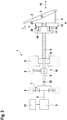
- Fig. 1 is a schematic illustration of a clutch actuator 1 for engaging and disengaging a clutch (not shown) connected to clutch actuation means in the form of a clutch lever 2 mounted in a vehicle to pivot about a pivot axis 3.
- the upper section of the clutch lever 2 is coupled to the disengagement bearing of the clutch and by swiveling motion of the clutch lever 2 (indicated by bend arrows), the disengagement bearing of the clutch is displaced to switch between the clutch engaged state and the clutch disengaged state.
- the lower end of the clutch lever 2 is connected to a push-rod 4 serving as a force transmitting element that couples the clutch lever 2 to the clutch actuator 1.
- the clutch actuator 1 comprises an electric motor 5 with an output shaft 6 connected to the sun gear of a planetary gear set 7, which is mounted in a housing 8 of the clutch actuator 1. For illustration purposes, only sections of the housing 8 are shown.
- the planetary gear set 7 is connected with its planet gears to a threaded spindle 9 with an outer thread section 10.
- a spindle nut 11 On the outer thread section 10 is mounted a spindle nut 11 which has an inner thread meshing with the outer thread 10 of the threaded spindle 9.
- the threaded spindle 9 is rotationally supported by a roller bearing 12 mounted in the housing 8.
- a roller bearing 12 mounted in the housing 8.
- the threaded spindle 9 may rotate about is longitudinal axis but is locked against axial displacement.
- the spindle nut 11 is rotatably fixed relative to the housing 8 by a longitudinal guidance (not shown) provided in the housing so that the spindle nut 11 is axially displaceable in the housing 8 but locked against rotation. Rotation of the threaded spindle 9 under the driving force provided by the electric motor 5 and transmitted through the planetary gear set 7 drives the spindle nut 11 in axial direction along the threaded spindle 9.
- the clutch actuator 1 further comprises a pressure piece 13 in the form of a plunger, which extends about the threaded spindle 9 but which is not engaged with the threaded spindle as the spindle nut 11.
- the pressure piece 13 is displaceable in axial direction 14 along the longitudinal axis of the threaded spindle 9, analogously to the spindle nut 11, wherein the pressure piece 13 is also guided in axial direction by a linear guidance (not shown) in the housing 8.
- the pressure piece 13 is further connected to the push-rod 4.
- the pressure piece 13 When the pressure piece 13 is displaced in axial direction 14, along the axis of the threaded spindle 9, it displaces the push-rod 4 which, in turn, actuates the clutch lever 2 to rotate the same about the pivot axis 3.
- Pressure piece 13 and spindle nut 11 are movable relative to each other in the axial direction 14 so that the spindle nut 11 and the pressure piece 13 may approach each other and may move away from each other.
- a biasing spring 15 is interposed between the spindle nut 11 and the pressure piece 13 and coupies the two elements with each other.
- the spindle nut 11 has at one end facing the pressure piece 13 a flange section 23 with a pocket 24 in the form of a recessed portion.
- the biasing spring 15 is inserted into the recess portion 24 and extends toward the pressure piece 13.
- the pressure piece 13 has in correspondence to the spindle nut 11 a flange section 25 that faces the flange section 23 of the spindle nut 11.
- the flange section 25 of the pressure piece 13 is flat.
- the recess portion 24 may be provided on the flange section 25 or both flange sections 23 and 25 may be provided with a recess portion to receive a respective end of the biasing spring 15.
- the position of the pressure piece 13 is linked to the condition of the clutch.
- the pressure piece 13 is axially moveable relative to the threaded spindle 9 between a first position A corresponding to the engaged state of the clutch and a second position B that corresponds to the disengaged state of the clutch.
- the spindle nut 11 is axially moveable relative to the threaded spindle 9 between a clutch engaging position C corresponding to the engaged state of the clutch and a second position D corresponding to the disengaged state of the clutch.
- the displacements between the positions A-B and C-D is respectively indicated by an arrow.
- Figure 1 illustrates the clutch actuator in a state that corresponds to the clutch engaged state.
- the clutch (not shown) has a clutch spring (not shown) which exerts a restoring force against the clutch lever, indicated by F, upon actuation of the clutch.
- F clutch lever
- the electric motor 5 provides a driving force and rotates the threaded spindle 9 in a first direction
- the spindle nut 11 is displaced in axial direction due to the thread engagement with the driving threaded spindle 9, approaches the pressure piece 13 and begins to compress the biasing spring 15 and then to displace the pressure piece 13 from position A to position B against the restoring force of the clutch.
- the spindle nut 11 approaches the pressure piece 13 until the flange section 23 of the spindle nut 11 engages the flange section 25 of the pressure piece 13 so that axial force is directly transmitted via the flange sections 23 and 25.
- the pressure piece 13 displaces the push rod 4 and the clutch lever 2 is rotated counterclockwise against the restoring force F of the clutch spring to disengage the clutch.
- the restoring force of the clutch acts against the driving torque of the electric motor 5 on the threaded spindle 9 through the push rod 4, the pressure piece 13, the biasing spring 15 and the spindle nut 11.
- the clutch lever 2 When the driving force is reduced below a predetermined level, the clutch lever 2 begins to rotate in clockwise direction and the pressure piece is moved backward from position B to position A and the spindle nut 11 is moved backward toward position C. Displacement of the spindle nut 11 toward position C rotates the spindle 11 and causes rotation of the threaded spindle 9.
- the biasing spring expands and displaces the spindle nut 11 away from the pressure piece 13 toward position C.
- a latching mechanism 16 is provided to limit displacement of the spindle nut 11 away from the pressure piece 13 under the force of the expanding biasing spring 15 and to hold the biasing spring in a preloaded state.
- Fig. 2 shows in cross section the latching mechanism 16 in a cross-sectional view along the axial direction 14.
- the latching mechanism comprises a disc 17 attached to the threaded spindle 9 in a rotatably fixed manner.
- the disc 17 is provided with a number of detent recesses 18 on its outer circumferential surface.
- a spring biased detent cam 19 is urged into engagement with detent disc 17 by means of a spring element 20.
- the detent cam moves from one detent recess 18 into the adjacent detent recess 18.
- the electric motor is activated by the control unit 21 which can adjust the output driving force of the electric motor.
- the threaded spindle is further provided with an absolute rotary encoder 22, e.g. a magnet element of a Hall-effect sensor.
- the corresponding sensor part is mounted on the housing but not shown.
- Fig. 3 shows the clutch actuator in a state corresponding to the disengaged stated of the clutch.
- the pressure piece 13 is in the second position B corresponding to the disengaged state of the clutch and the spindle nut 11 is in the clutch disengaging position D.
- the biasing spring 15 between the spindle nut 11 and the pressure piece 13 is compressed and the restoring force of the clutch acts on the pressure piece and through the compressed spring and the spindle nut 11 as an axial load on the threaded spindle 9.
- the biasing 15 is fully compressed and received in the recess portion 24. Due to the recess portion 24, the flange section 23 of the spindle nut 11 is in engagement with the flange section 25 of the pressure piece 13.
- the roller bearing 12 is of the type that supports radial and axial loads applied to the threaded spindle 9.
- the clutch is held in the disengaged state and the spindle nut 11 and the pressure piece 13 are retained in positions D, B by a driving force having a first value.
- the control unit 21, which controls the electric motor 5, is configured to measure the time the clutch is in the disengaged state.
- the above described rotary encoder may be used to provide the control unit with information if the spindle nut is in the clutch engaging or the clutch disengaging position and an internal timer of the control unit may measure the time.
- the control unit considers this condition to be a trigger condition that triggers a specific action by the control unit.
- the trigger control unit begins to reduce the driving force to a second value that is lower than the first value but that is above a threshold value at which the spindle nut leaves its position and begins to moves along the threaded spindle under the restoring force of the clutch.
Landscapes
- Engineering & Computer Science (AREA)
- General Engineering & Computer Science (AREA)
- Physics & Mathematics (AREA)
- Mechanical Engineering (AREA)
- Electromagnetism (AREA)
- Fluid Mechanics (AREA)
- Mechanical Operated Clutches (AREA)
Claims (8)
- Elektrisch angetriebener Kupplungsaktuator (1) zum Bestätigen der Kupplung eines Getriebes eines Fahrzeugs, mit:einer Gewindespindel (9), die durch einen Elektromotor zur Rotation angetrieben wird, undeiner Spindelmutter (11), die auf der Gewindespindel (9) montiert ist und die durch Drehung der Gewindespindel (9) aus einer Kupplungseinkuppelstellung (C) in eine Kupplungsauskuppelstellung (D) entsprechend Ein- und Auskupplung der Kupplung gegen die Rückstellkraft der Kupplung axial versetzbar ist, einer Steuereinheit (21) zum Aktivieren des Elektromotors, um eine Antriebskraft auf die Gewindespindel (9) zu übertragen, wobei die Steuereinheit (21) dazu eingerichtet ist, die Gewindemutter (11) mit einem ersten Wert der Antriebskraft in der Kupplungsauskuppelstellung (D) zu halten,dadurch gekennzeichnet, dass die Spindel (9) durch ein oder mehrere Kugellager (12) gelagert ist und dass die Steuereinheit (21) dazu eingerichtet ist, wenn die Spindelmutter (11) mit dem ersten Wert der Antriebskraft in der Kupplungsauskuppelstellung (D) gehalten wird, die Antriebskraft in Reaktion auf eine von der Steuereinheit erfasste Auslösebedingung auf einen zweiten Wert zu reduzieren, wobei der zweite Wert der Antriebskraft oberhalb eines Schwellenwertes liegt, bei dem die Spindelmutter (11) sich zu der Kupplungseinkuppelstellung (C) hin bewegt.
- Elektrisch angetriebener Kupplungsaktuator nach Anspruch 1, wobei die Steuereinheit (21) dazu eingerichtet ist, die Antriebskraft des Elektromotors (5) einzustellen.
- Elektrisch angetriebener Kupplungsaktuator nach Anspruch 1 oder 2, wobei die Auslösebedingung mit vorgegebenen Fahrbedingungen oder stationären Zuständen des Fahrzeugs zusammenhängt.
- Elektrisch angetriebener Kupplungsaktuator nach einem der Ansprüche 1-3, wobei die Auslösebedingung eine spezifische Zeitperiode ist, über die die Kupplung ausgekuppelt bleibt.
- Elektrisch angetriebener Kupplungsaktuator nach einem der Ansprüche 1-4, wobei die Steuereinheit (21) dazu eingerichtet ist, die Schritte auszuführen:1. Halten der Gewindespindel (11) mit dem ersten Wert der Antriebskraft in der Kupplungsauskuppelstellung (D),2. Überwachen der Verschiebung der Gewindespindel (9) oder der Spindelmutter (11) und graduelles Reduzieren der Antriebskraft, bis ein Schwellenwert der Antriebskraft erreicht ist, bei dem die Gewindemutter (11) beginnt, sich unter der Rückstellkraft der Kupplung relativ zur Gewindespindel (9) zu bewegen,3. graduelles Erhöhen der Antriebskraft über den Schwellenwert, bis die Gewindespindel (11) gestoppt ist und/oder in die Kupplungsauskuppelstellung (D) zurückgekehrt ist.
- Elektrisch angetriebener Kupplungsaktuator nach Anspruch 5, wobei die Steuereinheit (21) den zweiten Wert der Antriebskraft des Elektromotors (5) festlegt, indem die Schritte 1-3 von Anspruch 5 ausgeführt werden und der zum Stoppen und/oder Zurückkehren der Spindelmutter (11) in die Kupplungsauskuppelstellung (D) benötigte Wert der Antriebskraft in einem Speicher als ein zweiter Wert für spätere, mit der Auslösebedingung zusammenhängende Betätigungen der Kupplung gespeichert wird.
- Elektrisch angetriebener Kupplungsaktuator nach einem der Ansprüche 1-6, wobei ein Druckstück (13) vorgesehen ist, das axial zwischen einer ersten Position (A) und einer zweiten Position (B) entsprechend Einkuppeln und Auskuppeln der Kupplung beweglich ist,
wobei die Spindelmutter (11) und das Druckstück (13) in axialer Richtung (14) relativ zueinander beweglich sind und durch eine Vorspannfeder (15), die zwischen der Spindelmutter (11) und dem Druckstück (13) angeordnet ist, miteinander gekoppelt sind, so dass durch Drehung der Gewindespindel (9) mit einer Antriebskraft des Elektromotors (5) die Gewindemutter (11) die Vorspannfeder (15) komprimiert und das Druckstück (13) zu der zweiten Position (B) hin bewegt, um die Kupplung auszukuppeln. - Elektrisch angetriebener Kupplungsaktuator nach Anspruch 7, wobei die Vorspannfeder (15) in einem Hohlraumbereich (24) der Spindelmutter (11) oder des Druckstücks (13) vorgesehen ist, so dass die Spindelmutter (11) in Kontakt mit dem Druckstück (13) kommt, wenn die Vorspannfeder (15) komprimiert ist.
Applications Claiming Priority (1)
| Application Number | Priority Date | Filing Date | Title |
|---|---|---|---|
| PCT/EP2018/065618 WO2019238224A1 (en) | 2018-06-13 | 2018-06-13 | Electrically driven clutch actuator |
Publications (2)
| Publication Number | Publication Date |
|---|---|
| EP3755916A1 EP3755916A1 (de) | 2020-12-30 |
| EP3755916B1 true EP3755916B1 (de) | 2022-01-26 |
Family
ID=63014484
Family Applications (1)
| Application Number | Title | Priority Date | Filing Date |
|---|---|---|---|
| EP18745825.2A Active EP3755916B1 (de) | 2018-06-13 | 2018-06-13 | Elektrisch angetriebener kupplungsaktuator |
Country Status (4)
| Country | Link |
|---|---|
| US (1) | US11268580B2 (de) |
| EP (1) | EP3755916B1 (de) |
| CN (2) | CN114396435B (de) |
| WO (1) | WO2019238224A1 (de) |
Families Citing this family (3)
| Publication number | Priority date | Publication date | Assignee | Title |
|---|---|---|---|---|
| CN118434985A (zh) | 2021-12-23 | 2024-08-02 | 康斯博格汽车部件集团股份公司 | 螺杆和螺母线性驱动组件 |
| CN118511012A (zh) | 2022-05-04 | 2024-08-16 | 康斯博格汽车部件集团股份公司 | 用于确定电动离合致动器的力传递接触点的方法 |
| WO2025189384A1 (en) * | 2024-03-13 | 2025-09-18 | Apex Brands, Inc. | System and method for detecting clutch disengagement |
Family Cites Families (31)
| Publication number | Priority date | Publication date | Assignee | Title |
|---|---|---|---|---|
| GB1025105A (en) * | 1963-07-26 | 1966-04-06 | Ford Motor Co | Improvements in or relating to clutch release mechanisms |
| DE4320204A1 (de) * | 1993-06-18 | 1994-12-22 | Fichtel & Sachs Ag | Stellantrieb für eine Kraftfahrzeug-Reibungskupplung |
| GB2347723B (en) * | 1996-01-31 | 2000-11-22 | Luk Getriebe Systeme Gmbh | Actuator for use in a motor vehicle power train |
| JPH09309357A (ja) * | 1996-05-22 | 1997-12-02 | Honda Motor Co Ltd | 車両のヨーモーメント制御方法 |
| US6050379A (en) | 1998-07-10 | 2000-04-18 | Chrysler Corporation | Algorithm for electro-mechanical clutch actuator |
| AT5363U1 (de) * | 2001-07-31 | 2002-06-25 | Steyr Powertrain Ag & Co Kg | Verteilergetriebe mit steuerbarer reibungskupplung |
| DE10331927B3 (de) | 2003-07-15 | 2005-02-17 | Knorr-Bremse Systeme für Nutzfahrzeuge GmbH | Kupplungssteller |
| AU2005213848B2 (en) * | 2004-02-24 | 2010-11-04 | Linak A/S | A linear actuator comprising an overload clutch |
| DE102005023538A1 (de) * | 2004-06-18 | 2006-01-19 | Luk Lamellen Und Kupplungsbau Beteiligungs Kg | Doppelkupplungsgetriebe und Verfahren zum Ansteuern einer Kupplung eines Doppelkupplungsgetriebes |
| FR2895477B1 (fr) * | 2005-12-23 | 2009-05-22 | Renault Sas | Embrayage a friction commande automatiquement |
| DE102006035134A1 (de) * | 2006-07-29 | 2008-01-31 | Zf Friedrichshafen Ag | Kupplungssystem |
| ATE518073T1 (de) * | 2006-12-27 | 2011-08-15 | Schaeffler Technologies Gmbh | Verfahren und vorrichtung zum absichern einer referenzierung einer inkrementalwegmessung bei einer kupplungsaktorik |
| JP5015670B2 (ja) * | 2007-06-20 | 2012-08-29 | トヨタ自動車株式会社 | 車両用動力伝達装置の制御装置 |
| DE202009007977U1 (de) * | 2008-10-13 | 2010-02-25 | Magna Powertrain Ag & Co Kg | Kupplung |
| JP5302082B2 (ja) * | 2009-04-23 | 2013-10-02 | 株式会社日立ニコトランスミッション | 変速機およびその制御方法 |
| FR2954429B1 (fr) * | 2009-12-21 | 2012-03-09 | Valeo Embrayages | Dispositif d'actionnement a came pour un systeme d'embrayage a friction. |
| JP5431443B2 (ja) * | 2011-12-15 | 2014-03-05 | 株式会社エクセディ | クラッチのアクチュエータ |
| EP2836734B1 (de) * | 2012-04-10 | 2016-03-16 | Schaeffler Technologies AG & Co. KG | Verfahren zum betrieb einer betätigungsvorrichtung für eine kupplung |
| FR3022966B1 (fr) * | 2014-06-26 | 2016-06-10 | Valeo Embrayages | Actionneur pour un embrayage, notamment de vehicule automobile |
| DE102014217535A1 (de) * | 2014-09-03 | 2016-03-03 | Schaeffler Technologies AG & Co. KG | Magnetorheologischer Aktor und Kupplung mit solchem Aktor |
| CN105383274A (zh) * | 2014-09-04 | 2016-03-09 | 罗伯特·博世有限公司 | 车辆驱动系统以及其控制方法 |
| US10487887B2 (en) * | 2014-11-07 | 2019-11-26 | Means Industries, Inc. | Electromechanical apparatus for use with a controllable coupling assembly and coupling and electromechanical control assembly |
| DE102014224375A1 (de) * | 2014-11-28 | 2016-06-02 | Schaeffler Technologies AG & Co. KG | Reibungskupplung |
| JP6327184B2 (ja) * | 2015-03-20 | 2018-05-23 | トヨタ自動車株式会社 | セレクタブルワンウェイクラッチ |
| EP3073152B1 (de) * | 2015-03-24 | 2021-09-22 | KNORR-BREMSE Systeme für Nutzfahrzeuge GmbH | Linearaktuator mit vorspannung und verfahren zur steuerung eines solchen aktuators |
| CN107210673B (zh) * | 2015-03-27 | 2019-10-18 | 三菱电机株式会社 | 转换器装置 |
| CN108368894B (zh) * | 2015-11-25 | 2020-11-10 | 敏思工业公司 | 与可控连接组件一起使用的机电装置以及连接和机电控制组件 |
| SE542286C2 (en) * | 2016-01-25 | 2020-04-07 | Kongsberg Automotive As | Clutch Actuator for reducing Vibrations in a Clutch by a force-reducing gap |
| SE541641C2 (en) * | 2016-01-25 | 2019-11-19 | Kongsberg Automotive As | Failsafe electrical clutch actuator |
| ITUA20161890A1 (it) * | 2016-03-22 | 2017-09-22 | Dana Graziano Srl | Innesto a frizione per trasmissione di veicolo. |
| US10527111B2 (en) * | 2016-10-24 | 2020-01-07 | Deere & Company | Work vehicle drive assembly with electric motor overspeed protection |
-
2018
- 2018-06-13 EP EP18745825.2A patent/EP3755916B1/de active Active
- 2018-06-13 CN CN202210092884.2A patent/CN114396435B/zh active Active
- 2018-06-13 WO PCT/EP2018/065618 patent/WO2019238224A1/en not_active Ceased
- 2018-06-13 CN CN201880094596.2A patent/CN112334674B/zh active Active
- 2018-06-13 US US17/251,574 patent/US11268580B2/en active Active
Also Published As
| Publication number | Publication date |
|---|---|
| BR112020020177A2 (pt) | 2021-01-05 |
| CN114396435A (zh) | 2022-04-26 |
| CN112334674A (zh) | 2021-02-05 |
| US11268580B2 (en) | 2022-03-08 |
| CN112334674B (zh) | 2022-02-18 |
| WO2019238224A1 (en) | 2019-12-19 |
| US20210246951A1 (en) | 2021-08-12 |
| EP3755916A1 (de) | 2020-12-30 |
| CN114396435B (zh) | 2024-01-05 |
Similar Documents
| Publication | Publication Date | Title |
|---|---|---|
| EP1967434B1 (de) | Fahrzeugparksystem und Steuerverfahren dafür | |
| CN109476283B (zh) | 驻车制动器和操作方法 | |
| EP3755916B1 (de) | Elektrisch angetriebener kupplungsaktuator | |
| EP2687745B1 (de) | Bremsvorrichtung | |
| EP2962005B1 (de) | Stellglied | |
| CN105765259B (zh) | 操作液压离合器调节器的致动器和可电操作的离合器系统 | |
| EP2746122B1 (de) | Elektrische bremsvorrichtung | |
| CN109641583A (zh) | 用于车辆的盘式制动致动器 | |
| CN101517257A (zh) | 双离合器变速器的双离合器 | |
| CN108779813B (zh) | 减振离合器致动器 | |
| EP3622204A1 (de) | Linearantrieb mit sicherheitsmechanismus | |
| EP0902207B1 (de) | Automatische Kupplungssteuerungsvorrichtung | |
| EP3073152B1 (de) | Linearaktuator mit vorspannung und verfahren zur steuerung eines solchen aktuators | |
| US6561331B1 (en) | Transmission unit for a vehicle | |
| BR112020020177B1 (pt) | Acionador de embreagem acionado eletricamente | |
| KR101060036B1 (ko) | 트랜스퍼 케이스 | |
| US8910770B2 (en) | Gear change device for motor-vehicles | |
| JP3102610B2 (ja) | パワーシフタ | |
| US20250377029A1 (en) | Apparatus for drum brake assembly | |
| CN107435693A (zh) | 用于操纵车辆的离合器的装置 | |
| JP4348689B2 (ja) | 電子制御絞り弁装置 | |
| JP2006038171A (ja) | 電動式ブレーキ装置 |
Legal Events
| Date | Code | Title | Description |
|---|---|---|---|
| STAA | Information on the status of an ep patent application or granted ep patent |
Free format text: STATUS: UNKNOWN |
|
| STAA | Information on the status of an ep patent application or granted ep patent |
Free format text: STATUS: THE INTERNATIONAL PUBLICATION HAS BEEN MADE |
|
| PUAI | Public reference made under article 153(3) epc to a published international application that has entered the european phase |
Free format text: ORIGINAL CODE: 0009012 |
|
| STAA | Information on the status of an ep patent application or granted ep patent |
Free format text: STATUS: REQUEST FOR EXAMINATION WAS MADE |
|
| 17P | Request for examination filed |
Effective date: 20200922 |
|
| AK | Designated contracting states |
Kind code of ref document: A1 Designated state(s): AL AT BE BG CH CY CZ DE DK EE ES FI FR GB GR HR HU IE IS IT LI LT LU LV MC MK MT NL NO PL PT RO RS SE SI SK SM TR |
|
| AX | Request for extension of the european patent |
Extension state: BA ME |
|
| DAV | Request for validation of the european patent (deleted) | ||
| DAX | Request for extension of the european patent (deleted) | ||
| GRAP | Despatch of communication of intention to grant a patent |
Free format text: ORIGINAL CODE: EPIDOSNIGR1 |
|
| STAA | Information on the status of an ep patent application or granted ep patent |
Free format text: STATUS: GRANT OF PATENT IS INTENDED |
|
| INTG | Intention to grant announced |
Effective date: 20211117 |
|
| GRAS | Grant fee paid |
Free format text: ORIGINAL CODE: EPIDOSNIGR3 |
|
| GRAA | (expected) grant |
Free format text: ORIGINAL CODE: 0009210 |
|
| STAA | Information on the status of an ep patent application or granted ep patent |
Free format text: STATUS: THE PATENT HAS BEEN GRANTED |
|
| AK | Designated contracting states |
Kind code of ref document: B1 Designated state(s): AL AT BE BG CH CY CZ DE DK EE ES FI FR GB GR HR HU IE IS IT LI LT LU LV MC MK MT NL NO PL PT RO RS SE SI SK SM TR |
|
| REG | Reference to a national code |
Ref country code: GB Ref legal event code: FG4D |
|
| REG | Reference to a national code |
Ref country code: CH Ref legal event code: EP |
|
| REG | Reference to a national code |
Ref country code: SE Ref legal event code: TRGR |
|
| REG | Reference to a national code |
Ref country code: AT Ref legal event code: REF Ref document number: 1465514 Country of ref document: AT Kind code of ref document: T Effective date: 20220215 |
|
| REG | Reference to a national code |
Ref country code: IE Ref legal event code: FG4D |
|
| REG | Reference to a national code |
Ref country code: DE Ref legal event code: R096 Ref document number: 602018030091 Country of ref document: DE |
|
| REG | Reference to a national code |
Ref country code: LT Ref legal event code: MG9D |
|
| REG | Reference to a national code |
Ref country code: NL Ref legal event code: MP Effective date: 20220126 |
|
| REG | Reference to a national code |
Ref country code: AT Ref legal event code: MK05 Ref document number: 1465514 Country of ref document: AT Kind code of ref document: T Effective date: 20220126 |
|
| PG25 | Lapsed in a contracting state [announced via postgrant information from national office to epo] |
Ref country code: NL Free format text: LAPSE BECAUSE OF FAILURE TO SUBMIT A TRANSLATION OF THE DESCRIPTION OR TO PAY THE FEE WITHIN THE PRESCRIBED TIME-LIMIT Effective date: 20220126 |
|
| PG25 | Lapsed in a contracting state [announced via postgrant information from national office to epo] |
Ref country code: RS Free format text: LAPSE BECAUSE OF FAILURE TO SUBMIT A TRANSLATION OF THE DESCRIPTION OR TO PAY THE FEE WITHIN THE PRESCRIBED TIME-LIMIT Effective date: 20220126 Ref country code: PT Free format text: LAPSE BECAUSE OF FAILURE TO SUBMIT A TRANSLATION OF THE DESCRIPTION OR TO PAY THE FEE WITHIN THE PRESCRIBED TIME-LIMIT Effective date: 20220526 Ref country code: NO Free format text: LAPSE BECAUSE OF FAILURE TO SUBMIT A TRANSLATION OF THE DESCRIPTION OR TO PAY THE FEE WITHIN THE PRESCRIBED TIME-LIMIT Effective date: 20220426 Ref country code: LT Free format text: LAPSE BECAUSE OF FAILURE TO SUBMIT A TRANSLATION OF THE DESCRIPTION OR TO PAY THE FEE WITHIN THE PRESCRIBED TIME-LIMIT Effective date: 20220126 Ref country code: HR Free format text: LAPSE BECAUSE OF FAILURE TO SUBMIT A TRANSLATION OF THE DESCRIPTION OR TO PAY THE FEE WITHIN THE PRESCRIBED TIME-LIMIT Effective date: 20220126 Ref country code: ES Free format text: LAPSE BECAUSE OF FAILURE TO SUBMIT A TRANSLATION OF THE DESCRIPTION OR TO PAY THE FEE WITHIN THE PRESCRIBED TIME-LIMIT Effective date: 20220126 Ref country code: BG Free format text: LAPSE BECAUSE OF FAILURE TO SUBMIT A TRANSLATION OF THE DESCRIPTION OR TO PAY THE FEE WITHIN THE PRESCRIBED TIME-LIMIT Effective date: 20220426 |
|
| PG25 | Lapsed in a contracting state [announced via postgrant information from national office to epo] |
Ref country code: PL Free format text: LAPSE BECAUSE OF FAILURE TO SUBMIT A TRANSLATION OF THE DESCRIPTION OR TO PAY THE FEE WITHIN THE PRESCRIBED TIME-LIMIT Effective date: 20220126 Ref country code: LV Free format text: LAPSE BECAUSE OF FAILURE TO SUBMIT A TRANSLATION OF THE DESCRIPTION OR TO PAY THE FEE WITHIN THE PRESCRIBED TIME-LIMIT Effective date: 20220126 Ref country code: GR Free format text: LAPSE BECAUSE OF FAILURE TO SUBMIT A TRANSLATION OF THE DESCRIPTION OR TO PAY THE FEE WITHIN THE PRESCRIBED TIME-LIMIT Effective date: 20220427 Ref country code: FI Free format text: LAPSE BECAUSE OF FAILURE TO SUBMIT A TRANSLATION OF THE DESCRIPTION OR TO PAY THE FEE WITHIN THE PRESCRIBED TIME-LIMIT Effective date: 20220126 Ref country code: AT Free format text: LAPSE BECAUSE OF FAILURE TO SUBMIT A TRANSLATION OF THE DESCRIPTION OR TO PAY THE FEE WITHIN THE PRESCRIBED TIME-LIMIT Effective date: 20220126 |
|
| PG25 | Lapsed in a contracting state [announced via postgrant information from national office to epo] |
Ref country code: IS Free format text: LAPSE BECAUSE OF FAILURE TO SUBMIT A TRANSLATION OF THE DESCRIPTION OR TO PAY THE FEE WITHIN THE PRESCRIBED TIME-LIMIT Effective date: 20220526 |
|
| REG | Reference to a national code |
Ref country code: DE Ref legal event code: R097 Ref document number: 602018030091 Country of ref document: DE |
|
| PG25 | Lapsed in a contracting state [announced via postgrant information from national office to epo] |
Ref country code: SM Free format text: LAPSE BECAUSE OF FAILURE TO SUBMIT A TRANSLATION OF THE DESCRIPTION OR TO PAY THE FEE WITHIN THE PRESCRIBED TIME-LIMIT Effective date: 20220126 Ref country code: SK Free format text: LAPSE BECAUSE OF FAILURE TO SUBMIT A TRANSLATION OF THE DESCRIPTION OR TO PAY THE FEE WITHIN THE PRESCRIBED TIME-LIMIT Effective date: 20220126 Ref country code: RO Free format text: LAPSE BECAUSE OF FAILURE TO SUBMIT A TRANSLATION OF THE DESCRIPTION OR TO PAY THE FEE WITHIN THE PRESCRIBED TIME-LIMIT Effective date: 20220126 Ref country code: EE Free format text: LAPSE BECAUSE OF FAILURE TO SUBMIT A TRANSLATION OF THE DESCRIPTION OR TO PAY THE FEE WITHIN THE PRESCRIBED TIME-LIMIT Effective date: 20220126 Ref country code: DK Free format text: LAPSE BECAUSE OF FAILURE TO SUBMIT A TRANSLATION OF THE DESCRIPTION OR TO PAY THE FEE WITHIN THE PRESCRIBED TIME-LIMIT Effective date: 20220126 Ref country code: CZ Free format text: LAPSE BECAUSE OF FAILURE TO SUBMIT A TRANSLATION OF THE DESCRIPTION OR TO PAY THE FEE WITHIN THE PRESCRIBED TIME-LIMIT Effective date: 20220126 |
|
| PG25 | Lapsed in a contracting state [announced via postgrant information from national office to epo] |
Ref country code: AL Free format text: LAPSE BECAUSE OF FAILURE TO SUBMIT A TRANSLATION OF THE DESCRIPTION OR TO PAY THE FEE WITHIN THE PRESCRIBED TIME-LIMIT Effective date: 20220126 |
|
| PLBE | No opposition filed within time limit |
Free format text: ORIGINAL CODE: 0009261 |
|
| STAA | Information on the status of an ep patent application or granted ep patent |
Free format text: STATUS: NO OPPOSITION FILED WITHIN TIME LIMIT |
|
| REG | Reference to a national code |
Ref country code: DE Ref legal event code: R119 Ref document number: 602018030091 Country of ref document: DE |
|
| 26N | No opposition filed |
Effective date: 20221027 |
|
| PG25 | Lapsed in a contracting state [announced via postgrant information from national office to epo] |
Ref country code: MC Free format text: LAPSE BECAUSE OF FAILURE TO SUBMIT A TRANSLATION OF THE DESCRIPTION OR TO PAY THE FEE WITHIN THE PRESCRIBED TIME-LIMIT Effective date: 20220126 |
|
| REG | Reference to a national code |
Ref country code: CH Ref legal event code: PL |
|
| REG | Reference to a national code |
Ref country code: BE Ref legal event code: MM Effective date: 20220630 |
|
| PG25 | Lapsed in a contracting state [announced via postgrant information from national office to epo] |
Ref country code: SI Free format text: LAPSE BECAUSE OF FAILURE TO SUBMIT A TRANSLATION OF THE DESCRIPTION OR TO PAY THE FEE WITHIN THE PRESCRIBED TIME-LIMIT Effective date: 20220126 |
|
| GBPC | Gb: european patent ceased through non-payment of renewal fee |
Effective date: 20220613 |
|
| PG25 | Lapsed in a contracting state [announced via postgrant information from national office to epo] |
Ref country code: LU Free format text: LAPSE BECAUSE OF NON-PAYMENT OF DUE FEES Effective date: 20220613 Ref country code: LI Free format text: LAPSE BECAUSE OF NON-PAYMENT OF DUE FEES Effective date: 20220630 Ref country code: IE Free format text: LAPSE BECAUSE OF NON-PAYMENT OF DUE FEES Effective date: 20220613 Ref country code: FR Free format text: LAPSE BECAUSE OF NON-PAYMENT OF DUE FEES Effective date: 20220630 Ref country code: CH Free format text: LAPSE BECAUSE OF NON-PAYMENT OF DUE FEES Effective date: 20220630 |
|
| PG25 | Lapsed in a contracting state [announced via postgrant information from national office to epo] |
Ref country code: GB Free format text: LAPSE BECAUSE OF NON-PAYMENT OF DUE FEES Effective date: 20220613 Ref country code: DE Free format text: LAPSE BECAUSE OF NON-PAYMENT OF DUE FEES Effective date: 20230103 Ref country code: BE Free format text: LAPSE BECAUSE OF NON-PAYMENT OF DUE FEES Effective date: 20220630 |
|
| PG25 | Lapsed in a contracting state [announced via postgrant information from national office to epo] |
Ref country code: IT Free format text: LAPSE BECAUSE OF FAILURE TO SUBMIT A TRANSLATION OF THE DESCRIPTION OR TO PAY THE FEE WITHIN THE PRESCRIBED TIME-LIMIT Effective date: 20220126 |
|
| PG25 | Lapsed in a contracting state [announced via postgrant information from national office to epo] |
Ref country code: MK Free format text: LAPSE BECAUSE OF FAILURE TO SUBMIT A TRANSLATION OF THE DESCRIPTION OR TO PAY THE FEE WITHIN THE PRESCRIBED TIME-LIMIT Effective date: 20220126 Ref country code: CY Free format text: LAPSE BECAUSE OF FAILURE TO SUBMIT A TRANSLATION OF THE DESCRIPTION OR TO PAY THE FEE WITHIN THE PRESCRIBED TIME-LIMIT Effective date: 20220126 |
|
| PG25 | Lapsed in a contracting state [announced via postgrant information from national office to epo] |
Ref country code: HU Free format text: LAPSE BECAUSE OF FAILURE TO SUBMIT A TRANSLATION OF THE DESCRIPTION OR TO PAY THE FEE WITHIN THE PRESCRIBED TIME-LIMIT; INVALID AB INITIO Effective date: 20180613 |
|
| PG25 | Lapsed in a contracting state [announced via postgrant information from national office to epo] |
Ref country code: MT Free format text: LAPSE BECAUSE OF FAILURE TO SUBMIT A TRANSLATION OF THE DESCRIPTION OR TO PAY THE FEE WITHIN THE PRESCRIBED TIME-LIMIT Effective date: 20220126 |
|
| PGFP | Annual fee paid to national office [announced via postgrant information from national office to epo] |
Ref country code: SE Payment date: 20250514 Year of fee payment: 8 |
|
| PG25 | Lapsed in a contracting state [announced via postgrant information from national office to epo] |
Ref country code: TR Free format text: LAPSE BECAUSE OF FAILURE TO SUBMIT A TRANSLATION OF THE DESCRIPTION OR TO PAY THE FEE WITHIN THE PRESCRIBED TIME-LIMIT Effective date: 20220126 |